1
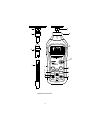
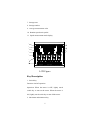
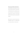
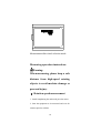
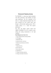
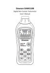
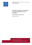
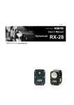
General Instructions
The MS6208A is a contact-type digital tachometer
with stable performance, high reliability and high
safety performance. The core component of the
meter is a compact high-speed integrated chip. The
meter
will
display
rotation
speeds
from
50RPM---19999RPM. The LCD is backlit to allow
making and reading measurements in low light
conditions.
Panel Diagram (see front view)
1. 6 in. idler wheel
2. Concave touch tip
3. Protruding touch tip
4. Lengthening bar
5. 0.1m idler wheel
6. Measurement bearing
7. Mode switch key
8. Measurement key
9. Data storage key
10. Backlight and HOLD composite key
11. Plus key
12. LCD
13. Power switch key
14. Maximum and minimum key
15. Data storage read key
16. Minus key
1
MODE
MIN
MAX
MEM
READ
MS6208A Front View
2
Accessories
1. 1 MS6208A bare machine
2. 1 Operation Manual
3. 2 measurement idler wheels
4. 2 measurement touch tips
5. 1 lengthening bar
6. 4 x 1.5V AAA battery
OOBA (out of box audit)
When you get a new tachometer, check the meter and
its accessories. If something is damaged or missing,
please contact the store where you bought the meter
to obtain missing items or to replace the meter..
Safety instructions
Operating environment:
● Elevation <2000 m
● Relative humidity (RH) ≦80%RH
● Operating temperature: 0 - 40°C
Warning
● To avoid damaging the meter or affecting
measurement accuracy, do not open the meter.
● Do not use the meter in the places with high
temperature and high humidity, or near flammable
and explosive materials.
3
● Storage and maintenance: Do not use alcohol or
other solvents to clean the meter. If it is not used for
long time, please remove batteries and put the meter
in a dry and clean environment.
Safety Symbols
Important safety information
Do not recycle
Low battery warning
The meter complies with CE
safety standard
LCD symbols description
1. Signal symbol
2. Idler wheel size symbol
3. Low battery symbol
4. Maximum measurement mode
5. Rotation speed reading
6. Minimum measurement mode
4
7. Storage state
8. Storage number
9. Average measurement value
10. Rotation speed unit symbol
11. Speed measurement mode display
1
7
2
8
3
9
10
4
5
6
LCD Figure
Key Description
1. Switch key
Function: On/Off operation
Operation: When the meter is OFF, lightly touch
switch key to turn on the meter. When the meter is
ON, lightly touch switch key to turn off the meter.
2. Maximum and minimum key
5
Function: Switch maximum, minimum and average
display value
Operation: When the LCD display is MAX, current
measurement is at maximum. When the LCD display
is MIN, current measurement is at minimum. When
the LCD display is AVG, current measurement is
average value.
3. Mode switch key
Function: Switch measurement mode
Operation: To operate mode switch key, select
measurement mode from 0 to 5, as appropriate for
conditions
4. Measurement key
Function: Switch measurement key
Operation: When turning on the meter, press the
measurement key to measure according to operating
instructions
5. Storage key
Function: Store current rotation speed value
Operation: When you want to store the current
rotation speed value, press the storage key together
with other keys, and you can store the current value
to the specified storage number.
6
6. Read key
Function: Read the rotation speed value under the
stored number.
Operation: When you want to store the rotation speed
value under a storage number, press the read key
together with other keys, and you can read the
rotation speed value under the stored number.
7. Backlight and HOLD key
Function: Turn on and off backlight
Operation: Quickly press backlight and HOLD keys
to turn on/off HOLD function. Press more than 2 sec
to turn on/off backlight function
8. Plus key
Function: Add storage number when reading or
storing
Operation: When entering storage state, use plus key
to add the current storage number
9. Minus key
Function: Subtract storage number when reading or
storing
Operation: When entering storage state, use plus key
to subtract the current storage number
7
Technical Parameter
I.
General specifications
1. Rotation speed display is five-digit LCD number
with maximum of 19999
2. Display 0 below 50 RPM
3. Measurement mode 0--5
4. Display voltage lower than 4.5V when batteries
are low
5. Dimension: 155mm x 60mm x 27
6. Weight: 120g
7. Power supply: 4 × 1.5V SIZEAAA battery
8. Auto off time is 30 sec
II. Technical parameter
Measuring scope
Resolution
50-99.99RPM
0.01RPM
100-9999.9RPM
0.1RPM
10000-19999
1RPM
8
Accuracy
±(0.03%±2d)
Measurement idler wheel selection
Hold the MODE key when turning on the meter to
enter idler wheel selection mode as shown below.
The default selection is the 0.1m idler wheel. At this
time, you can select 6", 12" or 0.1m of the wheel by
operating the plus or minus key. After selecting,
lightly press the MIN / MAX key to enter the normal
test mode.
Note: Select 0.1m of wheel for m/min and m/sec
measurement, or select 6" or 12" wheel for ft/min,
ft/sec and in/min. Otherwise, it will not measure
9
Measurement idler wheel selection mode
Measuring operation instructions
Warning:
When measuring, please keep a safe
distance from high-speed rotating
objects to avoid machine damage or
personal injury.
Ⅰ. Rotation speed measurement
1. Install lengthening bar and touch pit to the meter
2. Start the equipment to be measured and wait for
rotation speed to stabilize
10
3. Start the tachometer, enter the default speed
measurement mode, bring the meter gradually closer
to the rotating object, so that the touch pit can
smoothly contact the object to be measured. Press the
measurement key and read LCD display value.
Due to high lengthening bar pendulum
deflection, which will increase inaccuracy above
10000 RPM, please remove the lengthening bar if
object to be measured rotates at speed greater
than 10000 RPM.
Ⅱ. Speed measurement
1. Start the tachometer and enter the default speed
measurement mode. Select m/min, m/sec, t/min,
ft/sec or in/min mode through operating MODE key,
and the LCD will display the selected idler wheel
size.
2. Install the selected idler wheel.
11
3. Start the equipment to be measured and wait for
rotation speed to stabilize. Bring the idler wheel
gradually closer to the belt until it makes contact
with the belt, then read LCD display value.
Data storage and reading operation
I.
Data storage operation
When you want to store rotation speed value, press
MEM key in the non-HOLD state. MEM and default
storage number 00 will display on the upper right
corner of LCD. Press plus or minus key to select
storage number. At this time, if you press the
backlight key, the rotation speed value will flash. The
current rotation speed value can be stored in the
selected storage number. Exit the storage state by
pressing the READ key under the storage state.
II.
Data reading operation
When you want to read stored values, press READ
12
key in the non-HOLD state. The default storage
number 00 will display on the upper right corner of
LCD. Press plus or minus key to select storage
number and read the value in the current storage
number. Exit the storage state by operating MEM
key in the storage state.
Battery installation or replacement
When
symbol displays on LCD, it means low
batteries. Please change the batteries at this time. The
meter uses four 1.5V AAA batteries. To replace
batteries, open battery cover, remove the old batteries,
install new batteries of the correct size, according to
the illustration on the cover. Close the battery cover
after installation, and tighten screw before using the
Meter.
13