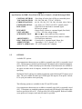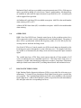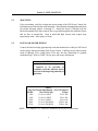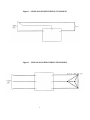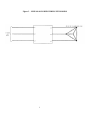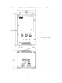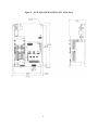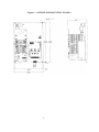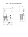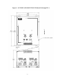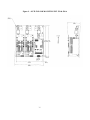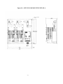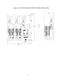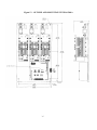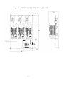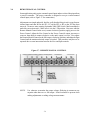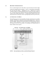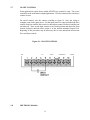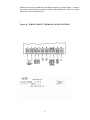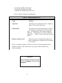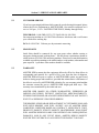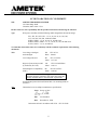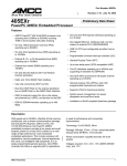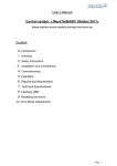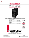
1
INSTALLATION, OPERATION and
MAINTENANCE MANUAL
MODEL ZF1, ZF2 and ZF3 rated 60 and 90 through 1200A
SINGLE PHASE and THREE PHASE – 2 or 3 LEG CONTROL
SCR POWER CONTROLS
UL/cUL FILE NUMBER – E151547
CE – See last page of manual for CE Declaration of Conformity
AMETEK HDR POWER SYSTEMS
3563 INTERCHANGE ROAD
COLUMBUS, OH 43204
TEL: 614-308-5500
TOLL FREE: 1-888-797-2685
FAX: 614-308-5506
SCR Power Controls/Systems & Power Supplies
Dear Client:
On behalf of all of AMETEK HDR's employees, I want to take this opportunity to "thank you" for
purchasing an AMETEK HDR Power Systems' SCR Power Control.
We believe AMETEK HDR represents the best overall solution to your SCR Power Control needs in
the industry today. We do this by providing a quality manufactured, reliable unit with fast, on-time
delivery and a competitive price.
All of our employees are dedicated to your success. If you have any questions, comments or
concerns, please call me toll free at 1-888-PWR-CNTL (797-2685).
Sincerely,
AMETEK HDR POWER SYSTEMS
George A. Sites
Vice President
GAS/be
3563 Interchange Road Columbus, OH 43204-1400 USA Telephone: 614-308-5500 1-888-PWR-C NTL FAX: 614-308-5506
REVISION PAGE
Page
Various
8/00
31
11/00
Change
Revision
1
Added DIP Switch information
2
Added EMC to CE Declaration
Date
NOTE: ALL SPECIFICATIONS SUBJECT TO CHANGE WITHOUT PRIOR NOTICE.
COPYRIGHT 2003
AMETEK HDR POWER SYSTEMS
TABLE OF CONTENTS
Para.
Title
Page
Section 1 - DESCRIPTION
1-1
1-2
1-3
1-4
1-5
1-6
1-7
Models Covered................................................................................................... 1
General Description.............................................................................................. 1
Applications ......................................................................................................... 1
Specifications....................................................................................................... 1
Options ................................................................................................................ 2
Operation............................................................................................................. 3
Diagnostic Indicators ........................................................................................... 3
Section 2 - INSTALLATION
2-1
2-2
2-3
2-4
2-5
Mounting ............................................................................................................. 4
Line/Load Power Wiring ...................................................................................... 4
Fan and Thermostat Wiring ................................................................................ 19
Input Line Voltage Changes ............................................................................... 21
Safety Issues 21
Section 3 - COMMAND SIGNAL CALIBRATION AND WIRING
3-1
3-2
3-3
3-4
3-5
3-6
3-7
3-8
Zero and Span Adjustments................................................................................ 23
Command Indicator............................................................................................ 23
Isolated and Non-Isolated Inputs........................................................................ 23
Remote Manual Control..................................................................................... 24
Process Command Signal ................................................................................... 25
Auto/Manual Control ......................................................................................... 25
ON/OFF Control................................................................................................ 26
Shutdown (Disable)............................................................................................ 27
Section 4 - MAINTENANCE
4-1
4-2
4-3
4-4
Environmental Concerns .................................................................................... 28
Line/Load Power Connections ........................................................................... 28
Static Precautions when Servicing ...................................................................... 28
Troubleshooting Typical Symptoms ................................................................... 28
i
Section 5 - SERVICE AND PARTS
5-1
5-2
5-3
Customer Service............................................................................................... 30
Spare Parts......................................................................................................... 30
Warranty............................................................................................................ 30
ii
TABLES and ILLUSTRATIONS
TABLES
Table
Title
1
2
3
4
Specifications............................................................................................................. 2
Lug Size/Torque Information .................................................................................... 4
Fan Power Requirements ......................................................................................... 20
Troubleshooting Zero Fired SCR Power Controllers .............................................. 29
Page
ILLUSTRATIONS
Figure
Title
Page
1
2
3
4
5
6
7
8
9
10
11
12
13
14
15
16
17
18
19
20
Line/Load Power Wiring – ZF1.................................................................................. 5
Line/Load Power Wiring – ZF2.................................................................................. 5
Line/Load Power Wiring – ZF3.................................................................................. 6
Outline and Mounting – ZF1 60 and 90 through 225A ............................................... 7
Outline and Mounting – ZF1 350 and 500A ............................................................... 8
Outline and Mounting – ZF1 650A............................................................................. 9
Outline and Mounting – ZF1 800 through 1200A..................................................... 10
Outline and Mounting – ZF2 60 and 90 through 225A ............................................. 11
Outline and Mounting – ZF2 350 and 500A ............................................................. 12
Outline and Mounting – ZF2 650A........................................................................... 13
Outline and Mounting – ZF2 800 through 1200A..................................................... 14
Outline and Mounting – ZF3 60 and 90 through 225A ............................................. 15
Outline and Mounting – ZF3 350 and 500A ............................................................. 16
Outline and Mounting – ZF3 650A........................................................................... 17
Outline and Mounting – ZF3 800 through 1200A..................................................... 18
Fan & Thermostat Terminals.................................................................................... 19
Remote Manual Control........................................................................................... 24
Auto/Manual Control............................................................................................... 25
ON/OFF Control...................................................................................................... 26
Firing Circuit Terminals & DIP Switches.................................................................. 27
iii
Section 1 - DESCRIPTION
1-1
MODELS COVERED
This manual covers the ZF1, ZF2 and ZF3 models rated 60 and 90 through 1200 amperes
and options.
1-2
GENERAL DESCRIPTION
The ZF1 is a single-phase, zero-fired (ZF) SCR Power Control. The ZF2 is three-phase
2-leg/4 SCR control and the ZF3 is a three-phase, 3-leg/6 SCR Power Controller. Each
of these will operate on voltages up to 575 Vac and accept most all standard process
command signals. Zero and Span multi-turn potentiometers are provided to ease
command signal calibration. HDR’s zero-fired SCR Power Controls utilize a variabletime-base that helps maintain constant power to the load. This variable-time-base also
helps minimize temperature overshoot, temperature fluctuations and helps extend the load
element’s life due to reduced thermal shock. The power SCR assemblies consist of two
SCRs connected back to back with a semiconductor fuse, RC Snubber and MOV
protection. The ZF1 has one power assembly while the ZF2 has two and the ZF3 has 3.
The firing circuit is based on common integrated circuits that provide very reliable
operation. Terminals are provided to ease installation. Diagnostic indicators are
included.
1-3
APPLICATIONS
Zero-Fired SCR Power Controls provide control of single or three-phase power by the
switching action of two SCRs connected back to back in each controlled phase. By
switching at the zero crossing point, RFI (Radio Frequency Interference) is virtually
eliminated. Zero-Fired controllers are versatile enough to be used in place of mechanical
contactors and mercury relays on dryers, kilns, ovens, environmental chambers, extruders,
molding equipment, and most other applications where resistive heating elements are
used. Normal Zero-Fired SCR Power Controllers should never be used on inductive
loads, if this is a requirement contact HDR Power Systems about their ZFT3 3-Phase,
Zero-Fired SCR Power Controller designed for firing into transformer primaries.
1-4
SPECIFICATIONS
Refer to Table 1 for specifications on HDR’s Zero-Fired SCR Power Controls.
1
Table 1
Specifications for HDR’s Zero-Fired SCR Power Controls - 60 and 90 through 1200A
CONTROL METHOD
VOLTAGE RATINGS
CURRENT RATINGS
COMMAND SIGNAL
ISOLATION
- Zero firing of back to back SCRs per controlled phase.
-120, 240, 400, 480, 575VAC, 50/60 Hz.
- 60, 90, 120, 180, 225, 350, 500, 650, 800, 1000, 1200 A.
- 4 to 20ma, 0 to 5VDC/0 to10VDC, manual control.
- 2500Vrms from line/load to command signal,
500Vrms to ground.
LINEARITY
- Output Power is linear to command signal (fixed load).
VOLTAGE REG.
- +1% for +10% line voltage change.
SCR PROTECTION
- Current surge, semi-conductor fuses; transient
voltage, metal oxide varistor (MOV) and R-C snubber
ADJUSTMENTS
- Zero and Span, multi-turn
DIAG. INDICATORS - Control power, command signal, blown fuse.
AMBIENT TEMP.
- Operating 0 - 50 °C, Storage -10 - 70 °C
AGENCY APPROVALS - UL, cUL Listed & CE Compliant
1-5
OPTIONS
Available ZF1 options:
Over-temperature thermostats are available as normally open (NO) or normally closed
(NC). Thermostats are included on 90 through 1200 ampere units as standard equipment,
specify NO or NC. Either normally open or normally closed thermostats are available as
an option on units rated 60 amperes, include NO or NC in your part number when
specifying.
Mechanical Line/Load lugs are standard equipment on the 60 through 225 ampere rated
units. They are available for units rated 350 through 1200 amperes as an option. Include
LG in your part number when specifying.
The following options are available for the ZF2 and ZF3 models:
Over-temperature thermostats are available as normally open (NO) or normally closed
(NC). Thermostats are standard equipment on units rated 90 through 1200 amperes but
needs to specified as NO or NC. If not specified, NO will be supplied. Both are available
as an option on 60 ampere rated units but must be specified.
2
Mechanical Line/Load lugs are available as an option on units rated 350 to 1200 amperes
and are specified by adding LG to the Power Control’s model number. Mechanical lugs
are standard on units rated 60 ampere but must be specified NO or NC – normally open
will be supplied if not specified.
An Unbalanced Load alarm (UB) is available as an option. Add UB to the model number
when ordering a ZF2 or ZF3.
A Shorted SCR Failure alarm (SF) is available as an option. Add SF to the model number
when ordering.
1-6
OPERATION
HDR’s Zero-Fired SCR Power Controls control power by the switching action of two
SCRs connected in a back to back configuration in each controlled phase. The gating of
these SCRs is synchronized with the line frequency (either 50 or 60 HZ) by the zero
crossing detector built into the firing circuit.
Zero-Fired SCR Power Controls turn the two SCRs in each phase on alternately as the
incoming power passes through the 0° point of the sine-wave. The length of time these
stay turned on is determined by the firing circuit and is based upon the input command
signal.
The variable-time-base (VTB) firing circuit ensures that the off time (number of off
cycles) is minimized for any command signal level. This helps ensure load power as
constant as possible while minimizing temperature overshoot, temperature fluctuations
and helps extend heater element life by avoiding thermal shock and mechanical stress.
1-7
DIAGNOSTIC INDICATORS
Light Emitting Diodes diagnostic indicators (LEDs) are provided for aid in start-up or
maintenance. A Control Power On indicator (Red) lights when the power controller has
power applied. The Command Signal indicator (Green) varies in brilliance with command
signal’s input level. A Blown Fuse indicator (Yellow) is provided for each semiconductor
fuse and lights when the corresponding fuse blows.
3
Section 2 - INSTALLATION
2-1
MOUNTING
Prior to mounting, verify the voltage and current rating of the SCR Power Control, the
information is provided on the unit's nameplate. Determine the mounting dimensions from
the outline drawings Figures 4 through 15. Mount the Power Controller with the
line/load terminals to the top so that air flow is upward through the heat sink fins. Ensure
that air flow is unrestricted. Keep in mind that high current units require large
input/output cable. Allow plenty of room.
2-2
LINE/LOAD POWER WIRING
Connect the line/load using appropriately sized and insulated wire/cable per NEC based
on the voltage and current rating of the Power Control. Cable lugs are provided on units
rated 60 through 225A, ratings above 225A have bus bar connections or optional
mechanical lugs. Refer to Table 2 for lug sizes and torque information.
WARNING
Branch circuit overcurrent protection
is required to be provided in
accordance with the national and/or
local code of the inspecting authority or
equivalent.
Table 2
Lug Size/Torque Information – 60 to 225 ampere
Model
Size Wire/Cable
Torque
60A
(1) 8 to 0 AWG
45 in. Lbs.
90A
(1) 8 to 0 AWG
45 in. Lbs.
120A
(1) 8 to 0 AWG
45 in. Lbs.
180A
(1) 6 to 250 MCM
250 in. Lbs.
225A
(1) 6 to 250 MCM
250 in. Lbs.
NOTE: U.L. requires 75°C rated wire (minimum) for all power connections.
4
Figure 1 - LINE/LOAD POWER WIRING ZF1 MODELS
Figure 2 – LINE/LOAD POWER WIRING ZF2 MODELS
5
Figure 3 – LINE/LOAD POWER WIRING ZF3 MODELS
6
Figure 4 - OUTLINE AND MOUNTING ZF1 60 and 90 through 225 A
7
Figure 5 – OUTLINE AND MOUNTING ZF1 350 & 500 A
8
Figure 6 – OUTLINE AND MOUNTING ZF1 650 A
9
Figure 7 – OUTLINE AND MOUNTING ZF1 800, 1000 & 1200 A
10
Figure 8 – OUTLINE AND MOUNTING ZF2 60 and 90 through 225 A
11
Figure 9 – OUTLINE AND MOUNTING ZF2 350 & 500 A
12
Figure 10 – OUTLINE AND MOUNTING ZF2 650 A
13
Figure 11 – OUTLINE AND MOUNTING ZF2 800, 1000 & 1200 A
14
Figure 12 – OUTLINE AND MOUNTING ZF3 60 and 90 through 225 A
15
Figure 13 – OUTLINE AND MOUNTING ZF3 350 & 500 A
16
Figure 14 – OUTLINE AND MOUNTING ZF3 650 A
17
Figure 15 – OUTLINE AND MOUNTING ZF3 800, 1000 & 1200 A
18
2-3
FAN AND THERMOSTAT WIRING
Fans and thermostats are supplied on all units above 90A. The user is responsible for
supplying 120VAC (unless otherwise specified) for the fan. Refer to Table 3 for the fan
power requirements based on the unit's current rating. Fan power should be connected
to terminals 21 and 22.
.
CAUTION
The application of fan power should precede or
coincide with the turn-on of the line voltage
source that is to be controlled by the disconnect
switch.
Normally Open (NO) thermostats are standard on all units above 90A, Normally Closed
(NC) thermostats may be specified. Normally Open or Normally Closed may be
specified on the 60A model as an option. Thermostats are on terminals 23 & 24.
Figure 16 – FAN and THERMOSTAT TERMINALS
19
Table 3 – Fan Power Requirements
Model ZF1
Rating
60A
90A
120A
180A
225A
350A
500A
650A
800A
1000A
1200A
Power Requirements
N/A
.21A, 25VA (50 Hz.); .19A, 23VA (60 Hz.)
.21A, 25VA (50 Hz.); .19A, 23VA (60 Hz.)
.21A, 25VA (50 Hz.); .19A, 23VA (60 Hz.)
.21A, 25VA (50 Hz.); .19A, 23VA (60 Hz.)
.21A, 25VA (50 Hz.); .19A, 23VA (60 Hz.)
.21A, 25VA (50 Hz.); .19A, 23VA (60 Hz.)
1.4A, 168VA (50 Hz.); 1.2A, 144VA (60 Hz.)
1.4A, 168VA (50 Hz.); 1.2A, 144VA (60 Hz.)
1.4A, 168VA (50 Hz.); 1.2A, 144VA (60 Hz.)
1.4A, 168VA (50 Hz.); 1.2A, 144VA (60 Hz.)
Model ZF2
Rating
60A
90A
120A
180A
225A
350A
500A
650A
800A
1000A
1200A
Power Requirements
N/A
.21A, 25VA (50 Hz.); .19A, 23VA (60 Hz.)
.21A, 25VA (50 Hz.); .19A, 23VA (60 Hz.)
.21A, 25VA (50 Hz.); .19A, 23VA (60 Hz.)
.21A, 25VA (50 Hz.); .19A, 23VA (60 Hz.)
.42A, 50VA (50 Hz.); .38A, 46VA (60 Hz.)
.42A, 50VA (50 Hz.); .38A, 46VA (60 Hz.)
2.8A, 336VA (50 Hz.); 2.4A, 288VA (60 Hz.)
2.8A, 336VA (50 Hz.); 2.4A, 288VA (60 Hz.)
2.8A, 336VA (50 Hz.); 2.4A, 288VA (60 Hz.)
2.8A, 336VA (50 Hz.); 2.4A, 288VA (60 Hz.)
Model ZF3
Rating
60A
90A
120A
180A
225A
350A
500A
650A
800A
1000A
1200A
Power Requirements
N/A
.42A, 50VA (50 Hz.); .38A, 46VA (60 Hz.)
.42A, 50VA (50 Hz.); .38A, 46VA (60 Hz.)
.42A, 50VA (50 Hz.); .38A, 46VA (60 Hz.)
.42A, 50VA (50 Hz.); .38A, 46VA (60 Hz.)
.63A, 76VA (50 Hz.); .57A, 69VA (60 Hz.)
.63A, 76VA (50 Hz.); .57A, 69VA (60 Hz.)
4.2A, 504VA (50 Hz.); 3.6A, 432VA (60 Hz.)
4.2A, 504VA (50 Hz.); 3.6A, 432VA (60 Hz.)
4.2A, 504VA (50 Hz.); 3.6A, 432VA (60 Hz.)
4.2A, 504VA (50 Hz.); 3.6A, 432VA (60 Hz.)
20
2-4
INPUT LINE VOLTAGE CHANGES
All units are shipped wired for the line voltage specified on the order. If some other
voltage is required, it is normally a simple matter to change it. Open the door on the
Power Control and locate transformer T1. Unsolder and move the white/black wire to
the appropriate voltage tap. On newer units (starting September 2000) DIP switches
have been added for selecting either 50 or 60 Hz. Operation.
WARNING
Hazardous voltages exist at the power controller
heat sinks and at the load at all times when the
input voltage is connected. This condition exists
even when the controller is set to deliver zero
output.
2-4
SAFETY ISSUES
The rated operational voltage of each power controller is shown on its nameplate, ie.
120V, 240V, 400V, 480V, or 575V. The power controller is designed to operate
between +10% and –15% of this rated operational voltage in an Over Voltage Category
III environment.
WARNING
Power control units are not suitable to
provide isolation due to the use of
semiconductors and other components
that allow a small current to flow from
line to load even when the unit is in the
non-conducting mode.
21
The voltage drop across the switching semiconductor while in the conducting mode is
approximately 1.5 volts and is somewhat a function of current. To calculate the power
control’s power loss, multiply the load current times 1.5 time the number of controlled
phases.
The minimum operational current is approximately 1 A and the maximum off state
current is approximately 15 ma.
The power controllers described in this instruction manual are designed to operate in a
pollution degree 2 environment.
HAZARDS EXIST
DANGEROUS VOLTAGES EXIST
22
Section 3 – COMMAND SIGNAL CALIBRATION AND WIRING
3-1
ZERO AND SPAN ADJUSTMENTS
All ZF series SCR Power Controllers have both Zero and Span potentiometers used for
matching the SCR Power Control and the Command Signal. The Zero control is for
the low end input (min. output) adjustments while the Span Control is used for the high
end input (max. output).
The Zero control has both negative and positive voltages available making it usable as a
manual or zero control. By turning the control clockwise, the output will increase
proportionally to the adjustment. Turning it counter-clockwise will decrease or zero
the output.
The Span control is used to adjust the maximum desired output. It will adjust for either
a remote manual control or a command signal input. Clockwise adjustment increases
the output while counter-clockwise adjustment decreases the output.
3-2
COMMAND INDICATOR
The Command Indicator is a green Light Emitting Diode (LED) located on the front
cover of the unit. The brilliance of this LED will change with the Command Signal.
The brilliance increases with an increased Command Signal and decreases with a
decreased Command Signal. The LED is usuable with 4-20ma Command Signals only
and will be bypassed for other signals.
3-3
ISOLATED AND NON-ISOLATED INPUTS
The Firing Circuit has the capability of having either an optically isolated or nonisolated Command Signal input. The Power Controller will always be shipped with an
isolated input unless specified otherwise (known exception is a Manual Control input.)
The standard input impedance is 500 ohms for isolated and 1500 ohms for non-isolated.
An isolated input can be changed to a non-isolated input by unsoldering jumpers J1 and
J2 on the firing circuit and moving them to the non-isolated position on the firing
circuit. On newer units (starting September 2000) DIP Switch 1 replaces J1 & J2.
The isolated input works best with an offset Command Signal such as 4-20ma however,
it will work with both offset and zero based Command Signals. Zero based Command
Signals may have a small amount of non-linearity (input to output) at the
low end. This normally is not a problem on closed loop systems.;
23
3-4
REMOTE MANUAL CONTROL
Some applications only require a manual control input and not a closed loop input from
a process controller. The power controller is designed to accept a remote manual
control input (refer to Figure 17 for connections.)
Adjustments are simple and quick, but first verify that the firing circuit is set up for nonisolated input and that R6 on the ZF1, R7 on the ZF2 or R5 on the ZF3 has been
removed. On newer units (starting September 2000) DIP Switch 2 has been added to
make this conversion easier. Make sure it is in the 1.5K position. Next start with the
Remote Manual Control in the zero (counter-clockwise) position, apply power to the
Power Control. Adjust the Zero Control so the Power Control's output just starts to
come on, then adjust it counter-clockwise so the unit's output is at zero. Now adjust
the Remote Manual Control to the full output (clockwise) position, and adjust the Span
Control until the maximum desired output is reached. This procedure may have to be
repeated due to some interaction between the Zero and Span controls.
Figure 17 – REMOTE MANUAL CONTROL
NOTE:
Use voltmeter to monitor the output voltage, flickering is common at any
setpoint other than zero or full output. Some load must be present when
making adjustments or taking voltage measurements.
24
3-5
PROCESS COMMAND SIGNAL
Process command signals can be either offset or zero based as discussed earlier. Simply
connect the command signal to terminals 1 (-) and 2 (+) on the firing circuit and adjust
the Zero and Span controls. Adjustments are easy. Simply have the process
controller's output set at minimum and adjust the Zero control so the unit's output is at
zero. Next have the process controller's output set at maximum and adjust the Span
control for the maximum desired output. As with the Remote Manual Control, some
interaction between controls does exist so repeating this procedure may be necessary.
3-6
AUTO/MANUAL CONTROL
On closed loop processes it may be desirable to be able to operate the power controller
manually. The HDR power controller has this capability designed into it. Connect the
Command Signal, a Remote Manual control and an Auto/Manual switch as shown in
Figure 18. Make adjustments as stated for the Process Command Signal with the
Auto/Manual switch in the Auto position. By switching to the Manual position, the
Remote Manual control operates.
Figure 18 – AUTO/MANUAL CONTROL
NOTE:
Some non-linearity will occur with the Manual Control.
25
3-7
ON/OFF CONTROL
Some applications require that a simple ON/OFF type control be used. The power
controller can be used in these simple applications. It can be connected for turn on by a
contact closure.
For on/off control, wire the contact according to figure 19. Once the wiring is
complete, turn on the input power. Set the input contact to open and adjust the Zero
control clockwise until the unit comes on, then adjust counter-clockwise until the unit
just shuts off. Now set the input contact to the closed position and adjust the Span
control clockwise until the unit's output is at the desired maximum output level.
Repeating of this procedure may be necessary due to some interaction between the
Zero and Span controls.
Figure 19 - ON/OFF CONTROL
3-8
SHUTDOWN (Disable)
26
When it is necessary to shutdown or disable the output, it is a simple matter. Connect a
dry contact closure between terminals 3 and 4 of the firing circuit. When it is closed,
the power control will be shut off.
Figure 20 – FIRING CIRCUIT TERMINALS & DIP SWITCHES
27
Section 4 - MAINTENANCE
4-1
ENVIRONMENTAL CONCERNS
Always verify that the SCR Power Controller is mounted in a clean, dust free
environment. Clean the heat sink(s) and printed circuit board periodically so no dust
and/or dirt accumulates on the unit. Dust and/or dirt on the heat sink fins can prevent
proper airflow causing overheating of the semiconductors. Conductive dust and/or dirt
can cause shorts or arcing, which can cause damage to the unit.
Always size your enclosure so that a 50 °C maximum internal ambient temperature is
never exceeded.
WARNING
DISCONNECT ALL SOURCES OF POWER TO THE POWER
CONTROLLER PRIOR TO CLEANING. THE UNIT IS NOT SUITABLE FOR
HOSE DOWN CLEANING. USE VACUUM, BRUSH OR LOW PRESSURE
AIR.
4-2
LINE/LOAD POWER CONNECTIONS
Periodically turn the power off to the SCR Power Controller and check for corrosion
and tightness of the power connections. If any corrosion is evident, clean the cable and
connector and reconnect making sure to tighten according to our torque specifications
in Table 2.
4-3
STATIC PRECAUTIONS WHEN SERVICING
When servicing the Firing Circuit Printed Circuit Board (PCB), damage can occur due
to static electricity. Always use a wrist strap grounded through a 1 megohm resistor.
Transport the PCB in a static shielding bag. Caution in handling the PCB can help
prevent any further damage to the PCB.
If you are not familiar with static precautions, consult the factory for additional details.
4-4
TROUBLESHOOTING TYPICAL SYMPTOMS
Any one of the following symptoms usually indicate a problem with the SCR Power
Controller.
28
1. No output regardless of the input.
2. Full output regardless of the input.
3. Output is not variable from zero to full.
Refer to Table 4 for help in troubleshooting.
Table 4 - TROUBLESHOOTING
Cause
Solution
1 . Open Fuse
Disconnect power and check the fuse. Replace if
faulty. If not, contact the factory.
2 . Shorted SCR
Disconnect power and check the SCRs. Measure
the resistance across the pair of SCRs (the load
must be disconnected), the resistance should be
infinite in both directions. If a short is indicated,
replace the
defective SCR or return the unit to the
factory.
3. Defective Firing Circuit
Disconnect power and unplug the Firing Circuit.
Order a replacement or return the Power Controller
to the factory.
NOTE: Virtually any failures of SCRs or Fuses on Zero-Fired equipment can be
attributed to short circuits in the load or loose power connections that cause
arcing or sparking.
WARNING
Always disconnect the power source
prior to attempting to service the
equipment.
29
Section 5 - SERVICE AND SPARE PARTS
5-1
CUSTOMER SERVICE
If you have operational problems which cannot be resolved using this manual, please
contact the Service Department at AMETEK HDR. Our normal work hours are 8
a.m. to 5:00 p.m., U.S.A. EASTERN TIME ZONE, Monday through Friday.
TELEPHONE: 1-888-PWR-CNTL (797-2685) OR 614-308-5500.
Our answering machine at 614-308-5500 will answer after hours and we will return
your call the next working day.
FAX: 614-308-5506. 24 hours per day automatic answering.
5-2
SPARE PARTS
Inside Sales should be contacted for any spare parts orders whether routine or
emergency during normal working hours. All after hours requirements should be
called in on our 614-308-5500 answering machine. Please have as much information
available as possible pertaining to the model number, serial number, order number and
parts required. A purchase order number should be available.
5-3
WARRANTY
AMETEK HDR warrants that the equipment delivered will be free from defects in
workmanship and material for a period of five years from the date of shipment.
AMETEK HDR will repair or replace, at AMETEK HDR's option, any part found
defective during proper and normal use, provided that written notice of the nature of
the defect is received by AMETEK HDR within the five year warranty period and that
the customer returns the part to AMETEK HDR freight paid both ways. This
warranty is not transferable by the initial end user.
AMETEK HDR MAKES NO OTHER WARRANTIES, EXPRESSED OR
IMPLIED (INCLUDING, WITHOUT LIMITATION, MERCHANTABILITY,
FITNESS FOR PURPOSE, OR AGAINST INFRINGEMENT OF ANY PATENT)
EXCEPT AS EXPRESSLY PROVIDED HEREIN.
THE REMEDY OF REPAIR OR REPLACEMENT IS CUSTOMER'S SOLE AND
EXCLUSIVE REMEDY AND WILL SATISFY ALL OF AMETEK HDR'S
LIABILITIES, WHETHER BASED ON CONTRACT, NEGLIGENCE, TORT,
PRODUCT LIABILITY, STRICT LIABILITY, OR OTHERWISE. IN NO EVENT
WILL AMETEK HDR BE LIABLE FOR INCIDENT OR CONSEQUENTIAL
DAMAGES, NOR IN ANY EVENT SHALL AMETEK HDR'S LIABILITY
EXCEED THE UNIT PRICE OF ANY DEFECTIVE PRODUCT OR PART.
30
EC DECLARATION OF CONFORMITY
WE:
AMETEK HDR POWER SYSTEMS
3563 Interchange Road
Columbus, Ohio 43204 - USA
Declare under our sole responsibility that the products listed below and bearing the CE label:
Type:
SCR power controllers with the following model designations and current ratings:
ZF1, ZF2, ZF3, PF1, PF3 - 15, 25, 40, 60, 70, 90, 120, 180,
225, 350, 500, 650, 800, 1000 and 1200A.
SHZF1, SHPF1 - 15, 30, 40, 60, 70, 90 and 120A
SHZF2, SHZF3, SHPF3 - 15, 25, 30, 60, 90, 120, 180 and 225A
SCZF1, SCPF1 - 15, 25, 40 and 65A
To which this declaration relates is in conformity with the technical requirements of the following
documents:
Title:
Low-voltage switchgear
and controlgear
No.
IEC 947-5-1
Year: 1990-03
Low Voltage Directive
No.
IEC 73/23/EEC
Year: 1973-02
Degrees of protection provided
by enclosures (IP Code):
Electromagnetic Compatibility
(EMC)
No.
Year:
IEC 529-2nd Edition
1989-11
No.
IEC 89/336/EEC
Year: 1989-05
Warning
All phase-fired (PF) controllers will require line filters and
possibly shielded cables to meet the EMC requirements.
(Environmental protection classification IP00 - for mounting inside an
enclosure)
Note:
Characteristics are according to manufactures specifications.
Name: George A. Sites
Title:
Vice President
Date:
November 10, 2000
Declaration written in accordance with I.S.O. - IEC/22 Guide
31