Download Advanced Function Setting Level
Transcript
Cat.No. H112–E1–1 E5AN Temperature Controller USER’S MANUAL E5AN Preface The temperature controller E5AN allows the user to carry out the following: • Select from many types of temperature, nonĆcontact temperature sensor and analog input • Select heating and cooling control in addition to standard control • Select AT (autoĆtuning) and ST (selfĆtuning) as tuning functions • Use multiĆSP and the run/stop function according to event input (for units equipped with the event input function) • Use the HBA (heater burnout alarm) function (for units equipped with the heater burnout alarm function) • Use the communications function (for units equipped with the communications function) • Calibrate sensor input • The E5AN features a watertight construction (NEMA4X : equivalent to IP66). • The E5AN conforms to UL/CSA/IEC safety standards and EMC standards. * This User's Manual describes how to use the E5AN. Before using your E5AN, thoroughly read and understand this manual in order to ensure correct use. Also, store this manual in a safe place so that it can be retrieved whenever necessary. * For an additional description of the communications function, also refer to the E5AN/EN/CN/GN Temperature Controller, Communications Function User's Manuals (Cat. No. H102). E OMRON, 1999 All rights reserved. No part of this publication may be reproduced, stored in a retrieval system or transmitted, in any form, or by any means, mechanical, electronic, photocopying, recording, or otherwise, without the prior written permission of OMRON. No patent liability is assumed with respect to the use of the information contained herein. Moreover, because OMRON is constantly striving to improve its high-quality products, the information contained in this manual is subject to change without notice. Every precaution has been taken in the preparation of this manual. Nevertheless, OMRON assumes no responsibility for errors or omissions. Neither is any liability assumed for damages resulting from the use of the information contained in this publication. I E5AN PRECAUTIONS When the product is used under the circumstances or environment described in this manual, always adhere to the limitations of the rating and functions. Also, for safety, take countermeasures such as fitting fail safe installations. DO NOT USE : • In circumstances or environments that have not been described below in this manual. • For control in nuclear power, railway, aircraft, vehicle, incinerator, medical, entertainment, or safety applications. • Where death or serious property damage may occur, or where extensive safety precautions are required. II E5AN SAFETY PRECAUTIONS JSafety Signal Words This manual uses the following signal words to mark safety precautions for the E5AN. These precautions provide important information for the safe application of the product. You must be sure to follow the instructions provided in all safety precautions. WARNING Indicates information that, if not heeded, could possibly result in loss of life or serious injury. CAUTION Indicates information that, if not heeded, could result in relatively serious or minor injury, damage to the product, or faulty operation. JSafety Precautions CAUTION F Electric Shock Warning Do not touch the terminals while the power is ON. Doing so may cause an electric shock. Do not allow metal fragments or lead wire scraps to fall inside this product. These may cause electric shock, fire or malfunction. Never disassemble, repair or modify the product. Doing so may cause electric shock, fire or malfunction. Do not operate this product in flammable and explosive gas atmospheres. The life expectancy of the output relays varies greatly with the switching capacity and other switching conditions. Always use the output relays within their rated load and electrical life expectancy. If an outĆ put relay is used beyond its life expectancy, its contacts may become fused or burned. Use this product within the rated load. Not doing so may cause damage or fire. Use this product within the rated supply voltage. Not doing so may cause damage or fire. Tighten the terminal screws to a torque of 0.74 to 0.90 Nm Loose screws may cause malfunction. Set all settings according to the control target of the product. If the settings are not appropriate for the control target, the product may operate in an unexpected manĆ ner, resulting in damage to the product or resulting in accidents. To maintain safety in the event of a product malfunction, always take appropriate safety measures, such as installing an alarm on a separate line to prevent excessive temperature rise. If a malfunction prevents proper control, a major accident may result. III E5AN NOTICE Be sure to observe these precautions to ensure safe use. (1) Do not wire unused terminals. (2) Be sure to wire properly with correct polarity of terminals. (3) To reduce induction noise, separate the highĆvoltage or largeĆcurrent power lines from other lines, and avoid parallel or common wiring with the power lines when you are wiring to the terminals. We recommend using separating pipes, ducts, or shielded lines. (4) Do not use this product in the following places: • Places subject to dust or corrosive gases (in particular, sulfide gas and ammonia gas) • Places subject to high humidity, condensation or freezing • Places subject to direct sunlight • Places subject to vibration and large shocks • Places subject to splashing liquid or oily atmosphere • Places directly subject to heat radiated from heating equipment • Places subject to intense temperature changes (5) To allow heat to escape, do not block the area around the product. (Ensure that enough space is left for the heat to escape.) • Do not block the ventilation holes on the casing. (6) When you draw out or draw in the internal mechanism or the terminal unit from the housing, never touch electrical components inside or subject the internal mechanism to shock. (7) Cleaning: Do not use paint thinner or the equivalent. Use standard grade alcohol to clean the product. (8) Use specified size (M3.5, width 7.2 mm or less) crimped terminals for wiring. (9) Allow as much space as possible between the E5AN and devices that generate powerful highĆfreĆ quency noise (e.g. highĆfrequency welders, highĆfrequency sewing machines) or surges. (10) When executing selfĆtuning, turn the load (e.g. heater) ON simultaneously or before you turn the the main unit ON. If you turn the the main unit ON before turning the load ON, correct selfĆtuning results and optimum control may no longer be obtained. (11) Use a 100 to 240 VAC (50/60 Hz), 24 VAC (50/60 Hz) or 24 VDC power supply matched to the power specifications of the E5AN. Also, make sure that rated voltage is attained within two seconds of turning the power ON. (12) Attach a surge suppressor or noise filter to peripheral devices that generate noise (in particular, motors, transformers, solenoids, magnetic coils or other equipment that have an inductance comĆ ponent). (13) When mounting a noise filter on the power supply, be sure to first check the filter's voltage and current capacity, and then mount the filter as close as possible to the E5AN. (14) Use within the following temperature and humidity ranges: • Temperature: Ć10 to 55_C, Humidity: 25 to 85% (with no icing or condensation) If the E5AN is installed inside a control board, the ambient temperature must be kept to under 55_C, including the temperature around the E5AN. If the E5AN is subjected to heat radiation, use a fan to cool the surface of the E5AN to under 55_C. (15) Store within the following temperature and humidity ranges: • Temperature: Ć25 to 65_C, Humidity: 25 to 85% (with no icing or condensation) (16) Never place heavy objects on, or apply pressure to the E5AN as it may cause it to deform and deteriĆ orate during use or storage. (17) Avoid using the E5AN in places near a radio, television set, or wireless installation. These devices can cause radio disturbances which adversely affect the performance of the E5AN. (18) Allow at least 30 minutes for the E5AN to warm up. (19) Locate a switch or circuit breaker and clearly indicate its position so that the operator can immediĆ ately turn the E5AN OFF. IV E5AN Conventions Used in This Manual JMeanings of Abbreviations The following abbreviations are used in parameter names, figures and in text explanations. These abbreviations mean the following: Symbol Term PV Process value SV Set value SP Set point AT AutoĆtuning ST SelfĆtuning EU Engineering unit *1 *1 _C, m, g and other units are indicated for scaled data. However, EU" is used as the minimum unit for the data. For example, for 50.02 (m)", 1 EU is taken as the minimum unit 0.01 (m). JHow to Read Display Symbols The following tables show the correspondence between the symbols displayed on the displays and alphabet characters. A B C D E F G H I J K L M N O P Q R S T U VW X Y Z V E5AN JHow This Manual is Organized Purpose D Learning about the E5AN Related title Chapter 1 INTRODUCTION Description This chapter describes the features, names of parts and typical functions. D Setting up the E5AN Chapter 2 PREPARATIONS This chapter describes instalĆ lation and wiring. D Basic operations Chapter 3 BASIC OPERATION and Chapter 5 PARAMETERS These chapters describe basic control examples. D Applied operations Chapter 4 APPLIED OPERATION and Chapter 5 PARAMETERS These chapters describe advanced functions to fully use E5AN. D Calibration Chapter 6 CALIBRATION This chapter describes calĆ ibration method. D Appendix VI This chapter describes the unit specifications. There is also a parameter operations list to be used as a backup guide to the parameter setĆ tings. Table of Contents Preface . . . . . . . . . . . . . . . . . . . . . . . . . . . . . . . . . . . . . . Precautions . . . . . . . . . . . . . . . . . . . . . . . . . . . . . . . . . . Safety Precautions . . . . . . . . . . . . . . . . . . . . . . . . . . . . Notice . . . . . . . . . . . . . . . . . . . . . . . . . . . . . . . . . . . . . . . Conventions Used in This Manual . . . . . . . . . . . . . . . CHAPTER 1 INTRODUCTION . . . . . . . . . . . . . . . . . . . . . . . . . . . 1–1 1.1 Names of Parts . . . . . . . . . . . . . . . . . . . . . . . . . . . . . . . . . . . . . . . . . . 1–2 Front panel . . . . . . . . . . . . . . . . . . . . . . . . . . . . . . . . . . . . . . . . . . . . . . . . . . . . . . . . . Display . . . . . . . . . . . . . . . . . . . . . . . . . . . . . . . . . . . . . . . . . . . . . . . . . . . . . . . . . . . . How to use keys . . . . . . . . . . . . . . . . . . . . . . . . . . . . . . . . . . . . . . . . . . . . . . . . . . . . 1–2 1–2 1–3 1.2 I/O Configuration and Main Functions . . . . . . . . . . . . . . . . . . . . . . 1–4 I/O configuration . . . . . . . . . . . . . . . . . . . . . . . . . . . . . . . . . . . . . . . . . . . . . . . . . . . . Main functions . . . . . . . . . . . . . . . . . . . . . . . . . . . . . . . . . . . . . . . . . . . . . . . . . . . . . . 1–4 1–5 1.3 How Setup Levels Are Configured and Operating the Keys on the Front Panel . . . . . . . . . . . . . . . . . . . . . . . . . . . . . . . 1–6 Selecting parameters . . . . . . . . . . . . . . . . . . . . . . . . . . . . . . . . . . . . . . . . . . . . . . . . Fixing settings . . . . . . . . . . . . . . . . . . . . . . . . . . . . . . . . . . . . . . . . . . . . . . . . . . . . . . 1–8 1–8 1.4 Communications Function . . . . . . . . . . . . . . . . . . . . . . . . . . . . . . . . 1–9 CHAPTER 2 PREPARATIONS . . . . . . . . . . . . . . . . . . . . . . . . . . . 2–1 2.1 Installation . . . . . . . . . . . . . . . . . . . . . . . . . . . . . . . . . . . . . . . . . . . . . . 2–2 Dimensions . . . . . . . . . . . . . . . . . . . . . . . . . . . . . . . . . . . . . . . . . . . . . . . . . . . . . . . . Panel cutout . . . . . . . . . . . . . . . . . . . . . . . . . . . . . . . . . . . . . . . . . . . . . . . . . . . . . . . . Setting up the option units . . . . . . . . . . . . . . . . . . . . . . . . . . . . . . . . . . . . . . . . . . . . Mounting . . . . . . . . . . . . . . . . . . . . . . . . . . . . . . . . . . . . . . . . . . . . . . . . . . . . . . . . . . . Draw out . . . . . . . . . . . . . . . . . . . . . . . . . . . . . . . . . . . . . . . . . . . . . . . . . . . . . . . . . . . 2–2 2–2 2–3 2–4 2–5 2.2 Wiring Terminals . . . . . . . . . . . . . . . . . . . . . . . . . . . . . . . . . . . . . . . . . 2–6 Terminal arrangement . . . . . . . . . . . . . . . . . . . . . . . . . . . . . . . . . . . . . . . . . . . . . . . Precautions when wiring . . . . . . . . . . . . . . . . . . . . . . . . . . . . . . . . . . . . . . . . . . . . . Wiring . . . . . . . . . . . . . . . . . . . . . . . . . . . . . . . . . . . . . . . . . . . . . . . . . . . . . . . . . . . . . 2–6 2–6 2–6 2.3 Requests at Installation . . . . . . . . . . . . . . . . . . . . . . . . . . . . . . . . . . . 2–10 To ensure prolonged use . . . . . . . . . . . . . . . . . . . . . . . . . . . . . . . . . . . . . . . . . . . . . To reduce the influence of noise . . . . . . . . . . . . . . . . . . . . . . . . . . . . . . . . . . . . . . . To ensure high–precision measurement . . . . . . . . . . . . . . . . . . . . . . . . . . . . . . . . About waterproofing . . . . . . . . . . . . . . . . . . . . . . . . . . . . . . . . . . . . . . . . . . . . . . . . . 2–10 2–10 2–10 2–11 CHAPTER 3 BASIC OPERATION . . . . . . . . . . . . . . . . . . . . . . . . 3–1 3.1 Initial Setup Examples . . . . . . . . . . . . . . . . . . . . . . . . . . . . . . . . . . . . 3.2 Setting the Input Type . . . . . . . . . . . . . . . . . . . . . . . . . . . . . . . . . . . . 3–2 3–4 Input type . . . . . . . . . . . . . . . . . . . . . . . . . . . . . . . . . . . . . . . . . . . . . . . . . . . . . . . . . . 3–4 3.3 Selecting _C/_F . . . . . . . . . . . . . . . . . . . . . . . . . . . . . . . . . . . . . . . . . 3–5 Temperature unit . . . . . . . . . . . . . . . . . . . . . . . . . . . . . . . . . . . . . . . . . . . . . . . . . . . . 3–5 3.4 Selecting PID Control or ON/OFF Control . . . . . . . . . . . . . . . . . . . 3.5 Setting Output Specifications . . . . . . . . . . . . . . . . . . . . . . . . . . . . . . 3–6 3–7 Control period . . . . . . . . . . . . . . . . . . . . . . . . . . . . . . . . . . . . . . . . . . . . . . . . . . . . . . Direct/reverse operation . . . . . . . . . . . . . . . . . . . . . . . . . . . . . . . . . . . . . . . . . . . . . . 3–7 3–7 I II III IV V 3.6 Setting the SP . . . . . . . . . . . . . . . . . . . . . . . . . . . . . . . . . . . . . . . . . . . 3–9 Changing the SP . . . . . . . . . . . . . . . . . . . . . . . . . . . . . . . . . . . . . . . . . . . . . . . . . . . . 3–9 3.7 Executing ON/OFF Control . . . . . . . . . . . . . . . . . . . . . . . . . . . . . . . . 3–10 ON/OFF Control . . . . . . . . . . . . . . . . . . . . . . . . . . . . . . . . . . . . . . . . . . . . . . . . . . . . Setup . . . . . . . . . . . . . . . . . . . . . . . . . . . . . . . . . . . . . . . . . . . . . . . . . . . . . . . . . . . . . . 3–10 3–11 3.8 Determining PID Constants (AT, ST, manual setup) . . . . . . . . . . . 3–12 AT.(auto-tuning) . . . . . . . . . . . . . . . . . . . . . . . . . . . . . . . . . . . . . . . . . . . . . . . . . . . . . ST (self-tuning) . . . . . . . . . . . . . . . . . . . . . . . . . . . . . . . . . . . . . . . . . . . . . . . . . . . . . ST start conditions . . . . . . . . . . . . . . . . . . . . . . . . . . . . . . . . . . . . . . . . . . . . . . . . . . ST stable range . . . . . . . . . . . . . . . . . . . . . . . . . . . . . . . . . . . . . . . . . . . . . . . . . . . . . Manual setup . . . . . . . . . . . . . . . . . . . . . . . . . . . . . . . . . . . . . . . . . . . . . . . . . . . . . . . 3–12 3–13 3–14 3–14 3–15 3.9 Alarm Outputs . . . . . . . . . . . . . . . . . . . . . . . . . . . . . . . . . . . . . . . . . . . 3–17 Alarm type . . . . . . . . . . . . . . . . . . . . . . . . . . . . . . . . . . . . . . . . . . . . . . . . . . . . . . . . . Alarm value . . . . . . . . . . . . . . . . . . . . . . . . . . . . . . . . . . . . . . . . . . . . . . . . . . . . . . . . 3–17 3–18 3.10 Heater Burnout Alarm (HBA) . . . . . . . . . . . . . . . . . . . . . . . . . . . . . . 3–19 HBA detection . . . . . . . . . . . . . . . . . . . . . . . . . . . . . . . . . . . . . . . . . . . . . . . . . . . . . . Operating conditions . . . . . . . . . . . . . . . . . . . . . . . . . . . . . . . . . . . . . . . . . . . . . . . . . Setup . . . . . . . . . . . . . . . . . . . . . . . . . . . . . . . . . . . . . . . . . . . . . . . . . . . . . . . . . . . . . . How to calculate detection current values . . . . . . . . . . . . . . . . . . . . . . . . . . . . . . . Example . . . . . . . . . . . . . . . . . . . . . . . . . . . . . . . . . . . . . . . . . . . . . . . . . . . . . . . . . . . 3–19 3–19 3–20 3–21 3–21 3.11 Requests during Operation . . . . . . . . . . . . . . . . . . . . . . . . . . . . . . . . 3–23 CHAPTER 4 APPLIED OPERATION . . . . . . . . . . . . . . . . . . . . . . 4–1 4.1 Shifting Input Values . . . . . . . . . . . . . . . . . . . . . . . . . . . . . . . . . . . . . 4–2 Shifting input . . . . . . . . . . . . . . . . . . . . . . . . . . . . . . . . . . . . . . . . . . . . . . . . . . . . . . . How to calculate input shift values (2-point shift) . . . . . . . . . . . . . . . . . . . . . . . . . 1-point shift method . . . . . . . . . . . . . . . . . . . . . . . . . . . . . . . . . . . . . . . . . . . . . . . . . 2-point shift method . . . . . . . . . . . . . . . . . . . . . . . . . . . . . . . . . . . . . . . . . . . . . . . . . Example of 2-point temperature input shift . . . . . . . . . . . . . . . . . . . . . . . . . . . . . . 4–2 4–3 4–4 4–4 4–5 4.2 Alarm Hysteresis . . . . . . . . . . . . . . . . . . . . . . . . . . . . . . . . . . . . . . . . 4–6 Standby sequence . . . . . . . . . . . . . . . . . . . . . . . . . . . . . . . . . . . . . . . . . . . . . . . . . . Close in alarm/open in alarm . . . . . . . . . . . . . . . . . . . . . . . . . . . . . . . . . . . . . . . . . . 4–6 4–7 4.3 Setting Scaling Upper and Lower Limits (analog input) . . . . . . . . 4–8 Analog input . . . . . . . . . . . . . . . . . . . . . . . . . . . . . . . . . . . . . . . . . . . . . . . . . . . . . . . . 4–8 4.4 Executing Heating and Cooling Control . . . . . . . . . . . . . . . . . . . . . 4–10 Heating and cooling control . . . . . . . . . . . . . . . . . . . . . . . . . . . . . . . . . . . . . . . . . . . Setup . . . . . . . . . . . . . . . . . . . . . . . . . . . . . . . . . . . . . . . . . . . . . . . . . . . . . . . . . . . . . . 4–10 4–11 4.5 Externally Setting the SP . . . . . . . . . . . . . . . . . . . . . . . . . . . . . . . . . 4–12 Setting event input . . . . . . . . . . . . . . . . . . . . . . . . . . . . . . . . . . . . . . . . . . . . . . . . . . How to use multi-SP . . . . . . . . . . . . . . . . . . . . . . . . . . . . . . . . . . . . . . . . . . . . . . . . . Setting by key operation . . . . . . . . . . . . . . . . . . . . . . . . . . . . . . . . . . . . . . . . . . . . . Setup . . . . . . . . . . . . . . . . . . . . . . . . . . . . . . . . . . . . . . . . . . . . . . . . . . . . . . . . . . . . . . Executing run/stop control . . . . . . . . . . . . . . . . . . . . . . . . . . . . . . . . . . . . . . . . . . . . 4–12 4–12 4–13 4–13 4–14 4.6 Setting the SP Upper and Lower Limit Values . . . . . . . . . . . . . . . 4–15 Set point limitter . . . . . . . . . . . . . . . . . . . . . . . . . . . . . . . . . . . . . . . . . . . . . . . . . . . . Setup . . . . . . . . . . . . . . . . . . . . . . . . . . . . . . . . . . . . . . . . . . . . . . . . . . . . . . . . . . . . . . 4–15 4–16 4.7 Executing the SP Ramp Function (limiting the SP change rate) 4–17 SP ramp . . . . . . . . . . . . . . . . . . . . . . . . . . . . . . . . . . . . . . . . . . . . . . . . . . . . . . . . . . . 4–17 4.8 To Move to the Advanced Function Setting Level . . . . . . . . . . . . 4.9 Using the Key Protect Level . . . . . . . . . . . . . . . . . . . . . . . . . . . . . . . 4–19 4–20 Key protect . . . . . . . . . . . . . . . . . . . . . . . . . . . . . . . . . . . . . . . . . . . . . . . . . . . . . . . . . 4–20 CHAPTER 5 PARAMETERS . . . . . . . . . . . . . . . . . . . . . . . . . . . . . 5–1 Conventions Used in this Chapter . . . . . . . . . . . . . . . . . . . . . . . . . . . . . . Meanings of icons used in this chapter . . . . . . . . . . . . . . . . . . . . . . . . . . About parameter display . . . . . . . . . . . . . . . . . . . . . . . . . . . . . . . . . . . . . . About the Order in Which Parameters Are Described in This Chapter Protect Level . . . . . . . . . . . . . . . . . . . . . . . . . . . . . . . . . . . . . . . . . . . . . . . . . Operation Level . . . . . . . . . . . . . . . . . . . . . . . . . . . . . . . . . . . . . . . . . . . . . . Adjustment Level . . . . . . . . . . . . . . . . . . . . . . . . . . . . . . . . . . . . . . . . . . . . . Initial Setting Level . . . . . . . . . . . . . . . . . . . . . . . . . . . . . . . . . . . . . . . . . . . Advanced Function Setting Level . . . . . . . . . . . . . . . . . . . . . . . . . . . . . . . Communications Setting Level . . . . . . . . . . . . . . . . . . . . . . . . . . . . . . . . . 5–2 5–2 5–2 5–2 5–3 5–4 5–11 5–19 5–27 5–40 CHAPTER 6 CALIBRATION . . . . . . . . . . . . . . . . . . . . . . . . . . . . . 6–1 6.1 6.2 6.3 6.4 6.5 6.6 Parameter Structure . . . . . . . . . . . . . . . . . . . . . . . . . . . . . . . . . . . . . User Calibration . . . . . . . . . . . . . . . . . . . . . . . . . . . . . . . . . . . . . . . . . Calibrating Thermocouples . . . . . . . . . . . . . . . . . . . . . . . . . . . . . . . . Calibrating Analog Input . . . . . . . . . . . . . . . . . . . . . . . . . . . . . . . . . . Calibrating Platinum Resistance Thermometers . . . . . . . . . . . . . Checking Indication Accuracy . . . . . . . . . . . . . . . . . . . . . . . . . . . . . 6–2 6–3 6–4 6–7 6–8 6–9 APPENDIX . . . . . . . . . . . . . . . . . . . . . . . . . . . . . . . . . . . . . . . . . . . . . A–1 SPECIFICATIONS . . . . . . . . . . . . . . . . . . . . . . . . . . . . . . . . . . . . . . . . . . . . A–2 Ratings . . . . . . . . . . . . . . . . . . . . . . . . . . . . . . . . . . . . . . . . . . . . . . . . . . . . . . . . . . . . Characteristics . . . . . . . . . . . . . . . . . . . . . . . . . . . . . . . . . . . . . . . . . . . . . . . . . . . . . . A–2 A–3 CURRENT TRANSFORMER (CT) . . . . . . . . . . . . . . . . . . . . . . . . . . . . . . ERROR DISPLAY . . . . . . . . . . . . . . . . . . . . . . . . . . . . . . . . . . . . . . . . . . . . PARAMETER OPERATIONS LIST . . . . . . . . . . . . . . . . . . . . . . . . . . . . . . Operation level . . . . . . . . . . . . . . . . . . . . . . . . . . . . . . . . . . . . . . . . . . . . . . . Adjustment level . . . . . . . . . . . . . . . . . . . . . . . . . . . . . . . . . . . . . . . . . . . . . . Initial Setting Level . . . . . . . . . . . . . . . . . . . . . . . . . . . . . . . . . . . . . . . . . . . Advanced function setting level . . . . . . . . . . . . . . . . . . . . . . . . . . . . . . . . . Protect level . . . . . . . . . . . . . . . . . . . . . . . . . . . . . . . . . . . . . . . . . . . . . . . . . Communications Setting Level . . . . . . . . . . . . . . . . . . . . . . . . . . . . . . . . . SENSOR INPUT SETTING AND INDICATION RANGES . . . . . . . . . . SETUP LEVELS DIAGRAM . . . . . . . . . . . . . . . . . . . . . . . . . . . . . . . . . . . . PARAMETER FLOW . . . . . . . . . . . . . . . . . . . . . . . . . . . . . . . . . . . . . . . . . . A–4 A–5 A–7 A–7 A–7 A–8 A–9 A–9 A–9 A–10 A–11 A–12 INDEX E5AN CHAPTER 1 INTRODUCTION 1 CHAPTER 1 INTRODUCTION 1.1 Names of Parts . . . . . . . . . . . . . . . . . . . . . . . . 1Ć2 Front panel . . . . . . . . . . . . . . . . . . . . . . . . . . . 1Ć2 Display . . . . . . . . . . . . . . . . . . . . . . . . . . . . . . . 1Ć2 How to use keys . . . . . . . . . . . . . . . . . . . . . . . 1Ć3 1.2 I/O Configuration and Main Functions . . . 1Ć4 I/O configuration . . . . . . . . . . . . . . . . . . . . . . . 1Ć4 Main functions . . . . . . . . . . . . . . . . . . . . . . . . 1Ć5 1.3 How Setup Levels Are Configured and Operating the Keys on the Front Panel . . . 1Ć6 Selecting parameters . . . . . . . . . . . . . . . . . . . 1Ć8 Fixing settings . . . . . . . . . . . . . . . . . . . . . . . . . 1Ć8 1.4 Communications Function . . . . . . . . . . . . . . 1Ć9 1–1 E5AN CHAPTER 1 INTRODUCTION 1.1 Names of Parts JFront panel Temperature unit No.1 display Operation indicators No.2 display Level key Mode key Down key Up key JDisplay F No.1 display Displays the process value or parameter type. ăLights for approximately one second during startup. F No.2 display Displays the set point, parameter operation read value or the manipulated variable. ăLights for approximately one second during startup. F Operation indicators (1) ALM1 (alarm 1) Lights when alarm 1 is ON. ALM2 (alarm 2) Lights when alarm 2 is ON. ALM3 (alarm 3) Lights when alarm 3 is ON. (2) HB (heater burnout alarm display) Lights when a heater burnout is detected. (3) OUT1, OUT2 (control output 1, control output 2) Lights when control output 1 and/or control output 2 are ON. HowĆ ever, whenever control output 1 is the current output, OUT1 stays off. (4) STOP (stop) Lights when operation is stopped. During operation, this indicator lights when an event or the run/stop function is stopped. Otherwise, this indicator stays off. (5) CMW (communications writing control) Lights when communications writing is enabled" and is out when it is disabled." 1–2 E5AN Names 1.1 of Parts F Temperature unit The temperature unit is displayed when the display unit parameter is set to a temperature. Indication is determined by the currently selected temĆ perature unit" parameter set value. When this parameter is set to _C", " is displayed, and when set to _F", " is displayed. Flashes during ST operation. JHow to use keys F (level) key The following describes the basic functions of the front panel keys. Press this key to select the setting levels. The setting level is selected in order operation level" ←→ adjustment level", initial setting level" ←→ communications setting level". F (mode) key Press this key to select parameters within each level. F (up) key Each press of this key increases values displayed on the No.2 display. HoldĆ ing down this key speeds up the incrementation. F (down) key Each press of this key decreases values displayed on the No.2 display. HoldĆ ing down this key speeds up the decrementation. F + key combination This key combination sets the E5AN to the protect level." For details on the protect level, see Chapter 5 Parameters. 1–3 E5AN CHAPTER 1 INTRODUCTION 1.2 I/O Configuration and Main Functions JI/O configuration OUT1 Control output 1 Temperature input/ analog input Control output 1 Control output 2 Heating and cooling HBA CT input OUT2 Alarm output 3 Standard ALM3 Controller * Event input 2ch Alarm 3 ALM2 SP input from external digital switch function and Run/Stop function Alarm output 2 Alarm 2 Alarm 1 ALM1 Alarm output 1 HBA HB “*” indicates optional items 1–4 Communications function * E5AN I/O 1.2Configuration and Main Functions JMain functions The following introduces the main functions of the E5AN. For details on each function and how to use the functions, see Chapter 3 onwards. F Input sensor types Ă• The following input sensors can be connected for temperature input: Thermocouple : K, J, T, E, L, U, N, R, S, B NonĆcontact temperature sensor type : ES1A : KĂ(10 to 70_C), KĂ(60 to 120_C), KĂ(115 to 165_C), ăK (160 to 260_C) Platinum resistance thermometer : Pt100, JPt100 Analog input : 0 to 50 mV F Control output Ă• Control output is either relay, voltage or current output depending on the model of E5AN. Ă• If heating and cooling control is selected on the E5ANĆj3jjj, alarm 3 output is used as cooling side output. Therefore, use alarm 1, 2 if an alarm is needed in heating and cooling control. F Alarms Ă• Set the alarm type and alarm value, or upperĆ and lowerĆlimit alarms. Ă• If necessary, a more comprehensive alarm function can be achieved by setting the standby sequence", alarm hysteresis" and close in alarm/ open in alarm" parameters. F Control adjustment Ă• Optimum PID constants can be set easily by AT (autoĆtuning) and ST (selfĆtuning). F Event input Ă• When equipped with the option event input unit E53ĆAKB, the following functions can be achieved by event input: Set point selection (multiĆSP max. 4 points) and run/stop F HBA Ă• The heater burnout alarm (HBA) function is supported when the option unit (E53ĆAKB/E53ĆAK01, or E53ĆAK03) is mounted in the E5AN. F Communications function Ă• Communications according to CompoWay/F* and Sysway are supported when the option communications unit E53ĆAK01, or E53ĆAK03 is mounted in the E5AN. Communications are carried out over the RSĆ485 interface. *1ăCompoWay/F is a generalĆpurpose serial communicationsĆbased uniĆ fied communications procedure developed by OMRON. CompoWay/F uses commands compliant with the wellĆestablished FINS, together with a uniĆ fied frame format on OMRON programmable controllers to facilitate communications between personal computers and components. *2ăSysway communication does not support alarm 3 output. 1–5 E5AN CHAPTER 1 INTRODUCTION 1.3 How Setup Levels Are Configured and Operating the Keys on the Front Panel Parameters are divided into groups, each called a level". Each of the set values (setup items) in these levels are called a parameter." The parameĆ ters on the E5AN are divided into the following seven levels: Power ON Operation level Adjustment level key Less than 1 second key + key The PV display flashes after one second. key 1 second min. 3 seconds min. Control stops. Initial setting level key Less than 1 second key 1 second min. key Communications setting level Protect level Password input set value “–169” Advanced function setting level Password input set value “1201” Control in progress Calibration level Control stopped * Protect level Operation level Adjustment level Initial setting level Advanced function setting level Calibration level Communications setting level Control in Progress Control Stopped f f f - f f f f * : To activate the advanced function setting level, set the Protect level" of the Initial/Communications protect" to 0". f : Indicates items that can be set. Of these levels, the initial setting level, communications setting level, advanced function setting level and calibration level can be used only when control has stopped. Note that controller outputs are stopped when any of these four levels are selected. 1–6 E5AN How 1.3 Setup Levels Are Configured and Operating the Keys on the Front Panel F Protect level Ă• To select this level, simultaneously press the and keys for at least one second. This level is for preventing unwanted or accidental modification of parameters. Protected levels will not be displayed, and so the parameters in that level cannot be modified. F Operation level Ă• This level is displayed when turning the power ON. It can be moved to the protect level, initial setting level and adjustment level from this level. Ă• Normally, select this level during operation. During operation, the proĆ cess value and manipulated variable can be monitored, and the set point, alarm value and upperĆ and lowerĆlimit alarms can be monitored and modified. F Adjustment level Ă• To select this level, press the key for less than one second. Ă• This level is for entering set values and offset values for control. This level contains parameters for setting the AT (autoĆtuning), communicaĆ tions writing enable/disable, hysteresis, multiĆSP, input shift values, heater burnout alarm (HBA) and PID constants. It can be moved to the top parameter of the initial setting level, protect level and operation level from here. F Initial setting level Ă• To select this level, press the key for at least three seconds in the operation level. The PV display flashes after one second. This level is for specifying the input type, selecting the control method, control period, setting direct/reverse action and alarm type. It can be moved to the advanced function setting level or communications setting level from this level. To return to the operation level, press the key for at least one second. To move to the communications setup level, press the key for less than one second. F Advanced function setting level Ă• To activate the advanced function setting level, after setting the ProĆ tect level" of the Initial/Communications protect" to 0", input the password (-169") in the initial setting level. Ă• It can be moved to the calibration level or initial level from this level. Ă• This level is for setting the automatic return of display mode, MV limitĆ ter, event input assignment, standby sequence, alarm hysteresis, ST (selfĆtuning) and for moving to the user calibration level. F Communications setting level key for less than one second in the iniĆ Ă• To select this level, press the tial setting level. When the communications function is used, set the communications conditions in this level. Communicating with a perĆ sonal computer (host computer) allows set points to be read and written, and manipulated variables to be monitored. F Calibration level Ă• To select this level, enter the password in the advanced function setting level. This level is for offsetting deviation in the input circuit. Ă• It can not be moved to other levels by operating the keys on the front panel from the calibration level. To cancel this level, turn the power OFF then back ON again. 1–7 E5AN CHAPTER 1 INTRODUCTION JSelecting parameters key. Each press of the Ă• To select parameters in each level, press the key advances to the next parameter. For details on each parameter, see Chapter 5. Parameter 1 Parameter 2 Parameter 3 Parameter n JFixing settings Ă• If the key is pressed at the final parameter, the display returns to the top parameter for the current level. Ă• To change parameter settings or setup, specify the setting using the or keys, and either leave the setting for at least two seconds or press the key. This fixes the setting. Ă• When another level is selected, the parameter and setting on the display are fixed. Ă• When the power is turned OFF, fix first the settings or parameter setup (by pressing the key). The settings and parameter setup are someĆ times not changed by merely pressing the or keys. 1–8 E5AN Communications 1.4 Function 1.4 Communications Function The E5AN can be provided with a communications function that allows you to check and set controller parameters on a host computer. If the communicaĆ tions function is required, mount the option unit E53ĆAK01 or E53ĆAK03 in the E5AN. For details on the communications function, see the separate Communications Functions User's Manual." Follow the procedure below to move to the communications setting level. (1) Press the key for at least three seconds in the operation level". The level moves to the initial setting level". (2) Press the key for less than one second. The initial setting level" moves to the communications setting level". key advances the parameters as shown in the followĆ (3) Pressing the ing figure. (4) Press the or keys to change the parameter setups. Communications unit No. Baud rate Data bit Stop bit Parity F Setting up communications data Parameter Set the E5AN communications specifications so that they match the comĆ munications setup of the host computer. In a multidrop 1:N configuration, match the setting data except the communications unit No. on all units. Unique communications unit Nos. must be set to each unit. Displayed Characters Set (monitor) Value Settings Default Unit 1 None 9.6 kbps Communications unit No. 0 to 99 Baud rate 1.2, 2.4, 4.8, 9.6, 19.2 Data bit 7, 8 7 bit Stop bit 1, 2 2 bit Parity None, even, odd Even None ., . , . , ., . , , 1–9 E5AN CHAPTER 1 INTRODUCTION 1–10 E5EN CHAPTER 2 PREPARATIONS 2 CHAPTER 2 PREPARATIONS 2.1 Installation . . . . . . . . . . . . . . . . . . . . . . . . . . . . 2Ć2 Dimensions . . . . . . . . . . . . . . . . . . . . . . . . . . . . 2Ć2 Panel cutout . . . . . . . . . . . . . . . . . . . . . . . . . . . 2Ć2 Mounting . . . . . . . . . . . . . . . . . . . . . . . . . . . . . 2Ć3 Draw out . . . . . . . . . . . . . . . . . . . . . . . . . . . . . . 2Ć4 2.2 Wiring Terminals . . . . . . . . . . . . . . . . . . . . . . 2Ć5 Terminal arrangement . . . . . . . . . . . . . . . . . 2Ć5 Precautions when wiring . . . . . . . . . . . . . . . 2Ć5 Wiring . . . . . . . . . . . . . . . . . . . . . . . . . . . . . . . . 2Ć5 2.3 Requests at Installation . . . . . . . . . . . . . . . . 2Ć10 To ensure prolonged use . . . . . . . . . . . . . . . . 2Ć10 To reduce the influence of noise . . . . . . . . . 2Ć10 To ensure high-precision measurement . . 2Ć10 About waterproofing . . . . . . . . . . . . . . . . . . . 2Ć11 2–1 E5AN CHAPTER 2 PREPARATIONS 2.1 Installation JDimensions (Unit: mm) 84.5 11.5 96 91 78 JPanel cutout (Unit: mm) +1.0 92 +0.8 –0 (96number of units -3.5) 0 92 +0.8 –0 120 min. +0.8 92 – 0 – Ă• Several units cannot be group mounted close together vertically. (Observe the recommended mounting space limits.) Ă• When group mounting several controllers, ensure that the surrounding temperature does not exceed the allowable operating temperature listed in the specifications. Ă• The recommended panel thickness is 1 to 8 mm. Ă• To ensure waterproofing, enclose the unit in the waterproof packing prior to mounting. Waterproofing is not possible when group mounting several units. 2–2 E5AN Installation 2.1 JSetting up the option units If communications, event input and heater burnout functions are required, mount the communications unit (E53ĆAK01 or AK03) or the event input unit (E53ĆAKB). The heater burnout function is supported on either of these two option units. F Option units Name Communications unit Event input unit Model Function E53-AK01 Communications (RS-232C) E53-AK03 Communications (RS-485) E53-AKB Event input Ă• Terminal label:x 1 F Assembling the unit (1) Regular flat blade screwdriver (units: mm) 20 min. (4) (2) (1) (3) (1) Insert the tools (see drawing above) into the slots (one on the top and one on the bottom) and release the hooks. (2) Insert the tool into the gap between the front and rear, and slightly draw out the front panel. Then, draw out the front panel towards you holding it by its top and bottom sides. (3) Match the upper and lower claws with the connection points and insert the option unit. Mount the option unit in the center. (4) Before you push the unit back into the case, make sure that the waterĆ tight packing is in place. Push the unit back into the rear case until you hear a click. When you do this, hold down the hooks on the top and bottom of the rear case so that they are firmly hooked in place. 2–3 E5AN CHAPTER 2 PREPARATIONS JMounting Adaptor Terminal cover F How to attach the E5AN on the panel (1) Insert the main unit through the mounting hole in the panel (1Ć8 mm thickness). Pull the adapter along the body of the main unit from rear case up to the panel and fasten temporarily. (2) Tighten the upper and lower screws alternately with only one turn of the screwdriver at a time to maintain an even torque balance. F How to attach the terminal cover Fit terminal cover E53-COV11 onto the upper and lower hooks. Attach the terminal cover so that the OMRON mark of terminal Nos.1 to 10 faces down and the OMRON mark of terminal Nos.11 to 20 faces up. If the cover is attached the other way round, the fixture can no longer be atĆ tached. 2–4 E5AN Installation 2.1 JDraw out The main unit can be drawn out to perform maintenance without removĆ ing the terminal compartment. (1) (2) (3) Prepare a screwdriver that can be used on the lower front screw of the unit. (1) Loosen the lower front screw with a screwdriver (turning left) while pushing the hook on the upper surface of the front panel. (2) Grasp both sides of the front panel and draw (pull) it out. (3) Ensure that the waterproof packing is in place before drawing in the unit. ReĆtighten the lower front screw with a screwdriver (turning right) to a torque of 0.3 to 0.5 Nm while pushing the hook on the upper surface of the front panel. 2–5 E5AN CHAPTER 2 PREPARATIONS 2.2 Wiring Terminals JTerminal to 240V arrangement AC100V AC/DC 24V Voltage output/ Relay output DC12V 40mA AC250V 5A (Resistive load) Current output Input power OUT1 ALM3/OUT2 Alarm output AC250V 3A (Resistive load) ALM2 1 11 2 12 3 13 4 14 5 15 6 16 7 17 8 18 9 ALM1/Heater burnout JPrecautions when wiring RS-232C Event input (No polarity) EV2 EV1 RS-485 11 SD 11 B (+) 12 RD 12 A (–) 13 SG 13 Do not use CT A B B TC Analog input Pt 10 Ă• Separate input leads and power lines in order to protect the E5AN and its lines from external noise. Ă• Use AWG28 or larger twisted pair cable. AWG28 or larger Conductor cross-section 0.08042mm2 or larger Ă• It's recommended to use solderless terminals when wiring the E5AN. Ă• Tighten the terminal screws using a torque no greater than 0.74 to 0.90 Nm. Ă• Use the following type of solderless terminals for M3.5 screws. 7.2 mm max. 7.2 mm max. JWiring F Power supply Ă• Connect to terminal Nos. 1 to 2. The following table shows the specificaĆ tions. Input power supply E5AN 100 to 240 VAC, 50/60 Hz 9VA 24 VAC, 50/60 Hz 5VA 24 VDC (no polarity) 4W Ă• Standard insulation is applied to the power supply I/O sections. If reinĆ forced insulation is required, connect the input and output terminals to a device without any exposed currentĆcarrying parts or to a device with standard insulation suitable for the maximum operating voltage of the power supply I/O section. 2–6 E5AN Wiring 2.2 Terminals F Input Ă• Connect to terminal Nos.16 to 18 as follows according to the input type. 16 17 - 16 17 16 17 18 18 18 + v + Thermocouple Platinum resistance Analog thermometer input F Control output 1 Ă• Terminal Nos. 3 to 4 are for control output. The following diagrams show the available outputs and their internal equalizing circuits. +V +V + 3 3 3 L 4 Relay GND + L GND 4 4 – Voltage – Current Ă• The following table shows the specifications for each output type. Output type Specifications Relay 250 VAC, 5A (resistive load) electrical life : 100,000 operations Voltage (PNP) (with short-circuit protection) Current DC12V "15%FS 21mA max. +15% – 20%FS DC12V DC4–20mA 40mA max. load : 600Ω max. resolution : approx. 2600 Ă• The voltage output (control output) is not electrically insulated from the internal circuits. When using a grounding thermocouple, do not connect the control output terminals to the ground. If the control output termiĆ nals are connected to the ground, errors will occur in the measured temĆ perature values as a result of leakage current. F Alarm output/Control output 2 Ă• On the E5ANĆV3VVVĂ,Ăalarm output 1 (ALM1) is between terminal Nos. 9 and 10, alarm output 2 (ALM2) is between terminal Nos. 7 and 8 and alarm output 3 (ALM3) is between terminal Nos. 5 and 6. When utilizing heating and cooling control, alarm output 2 becomes alarm output 3 and alarm output 3 is not available. Ă• When the option unit E5ANĆjjHjj is mounted on the E5AN, an OR of alarm output 1 and the heater burnout alarm will be output. To disĆ able alarm output 1 and output only the heater burnout alarm on termiĆ nals 7 and 8, set the mode of the alarm output 1 to 0. Ă• The interior equivalent circuits of alarm output 1, 2 and 3 are shown in the following diagram. 5 ALM3/OUT2 6 7 ALM2 8 9 ALM1/Heater burnout alarm 10 Ă• Relay specifications are as follows: SPSTĆNO : 3A 250VAC 2–7 E5AN CHAPTER 2 PREPARATIONS F CT input Ă• When the option unit E53ĆAKB, E53ĆAK01, or E53ĆAK03 is mounted on the E5AN and the heater burnout function is used, connect a current transformer (CT) across terminal Nos. 14 and 15. 14 CT 15 F Event input Ă• When the option event input unit E53ĆAKB is mounted on the E5AN and event input is used, connect to terminal Nos. 11 to 13. 11 EV1 12 EV2 13 Ă• Use event inputs under the following conditions: Contact input ON: 1 kΩ max., OFF: 100 kΩ min. No-contact input ON: residual voltage 1.5 V max., OFF: leakage current 0.1 mA max. Polarities during noĆcontact input are as follows: 11 12 13 F Communications EV1 + EV2 – Ă• When the option communications unit E53ĆAK01 is mounted in the E5AN for communications, connect the communications cable to termiĆ nal Nos. 11, 12 and 13. 11 12 13 2–8 + SD RD SG RS-232C E5AN Wiring 2.2 Terminals Communications unit connection diagram Host computer E5AN RS-232C : 25P No. RS-232C 1 FG No. 2 SD 11 SD 3 RD 12 RD 4 RS 13 SG 5 CS 6 DR 20 ER 7 SG Shielded cable Ă• The RSĆ232C connection is 1:1 Ă• The maximum cable length is 15 m. Use the RSĆ232C optical interface cable (Z3RN) as an extension cable if necessary. Ă• Use shielded, twisted pair cable (AWG28 min.). Ă• When the E53ĆAK03 is mounted in the E5AN for communications, conĆ nect the communications cable to terminal Nos. 11 and 12. 11 B(+) 12 A(–) RS-485 Communications unit connection diagram Host computer RS-485 Shielded cable + FG A<B : “1” mark A>B : “2” space E5AN (No.1) RS-485 No Abbr. 12 A (–) 11 B (+) E5AN (No.31) RS-485 No Abbr. 12 A (–) 11 B (+) Terminator (120Ω, 1/2 W) Ă• The RSĆ485 connection can either be 1:1 or 1:N. Up to 32 units including the host computer can be connected 1:N. Use shielded, twisted pair cable (AWG28 min.) and keep the total cable length to within 500m. Cable reference diagram AWG28 min. Conductor area cross-section 0.081mm2 min. 2–9 E5AN CHAPTER 2 PREPARATIONS 2.3 Requests at Installation JTo ensure prolonged use Use the temperature in the following operating environment: Temperature : -10 to +55°C (icing and condensation not allowed) Humidity : 25 to 85% When the temperature controller is incorporated in a control panel, make sure that the controller's ambient temperature and not the panel's ambiĆ ent temperature does not exceed 55°C. The life of electronic equipment such as temperature controllers is inĆ fluenced not only by the life determined by the relay switching count but also by the life of the electronic components used internally. The service life of components is dependent on the ambient temperature: the higher the ambient temperature becomes, the shorter the service life becomes, and vice versa. For this reason, the service life of the temperature controlĆ ler can be extended by lowering its internal temperature. Gang-mounting two or more temperature controllers, or mounting temperĆ ature controllers above each other may cause heat to build up inside the temĆ perature controllers, which will shorten their service life. When mounting temperature controllers like this, forced cooling measures such as a cooling fan for cooling the temperature controllers must be taken into consideration. Prevent only the terminal block from being cooled. Otherwise, this may result in a measurement error. JTo reduce the influence of noise To reduce induction noise, the leads on the temperature controller's terĆ minal block must be wired separately from large-voltage/large-current power leads. Also, avoid wiring leads in parallel with power leads or in the same wiring path. Other methods such as separating conduits and wiring ducts, or using shield wire are also effective. Attach a surge absorber or noise filter to peripheral equipment that generĆ ates noise (in particular, motors, transformers, solenoids, or other equipĆ ment that has a magnetic coil or other inductance component). When a noise filter is used at the power supply, first check the voltage or current, and attach the noise filter as close as possible to the temperature controller. Also, install the temperature controller as far away as possible from equipĆ ment that generates strong, high frequency (e.g. high-frequency welders, high-frequency sewing machines) or surges. JTo ensure high–precision measurement When the thermocouple leads are extended, be sure to use a compensating lead wire matched to the type of thermocouple. When the platinum resistance detector leads are extended, use the lead having the smallest resistance to equalize the resistance of the three leads. Install the temperature controller so that it is horizontal. If there is a large error in the measurement values, make sure that input compensation has been set correctly. 2–10 E5AN Requests 2.3 at Installation JAbout waterproofing The protective structure of this controller conforms to the following stanĆ dards. Parts that are not indicated as being protected or that are indicated as IPj0 are not waterproof. Front panel: NEMA 4 for indoor use (equivalent to IP66) Rear case: IP20 Terminals: IP00 2–11 E5AN CHAPTER 2 PREPARATIONS 2–12 E5AN CHAPTER 3 BASIC OPERATION 3 CHAPTER 3 BASIC OPERATION 3.1 Initial Setup Examples . . . . . . . . . . . . . . . . . 3.2 Setting the Input Type . . . . . . . . . . . . . . . . . Input type . . . . . . . . . . . . . . . . . . . . . . . . . . . . . 3.3 Selecting _C/_F . . . . . . . . . . . . . . . . . . . . . . . . Temperature unit . . . . . . . . . . . . . . . . . . . . . . 3.4 Selecting PID Control or ON/OFF Control 3.5 Setting Output Specifications . . . . . . . . . . . Control period . . . . . . . . . . . . . . . . . . . . . . . . . Direct/reverse operation . . . . . . . . . . . . . . . . 3.6 Setting the SP . . . . . . . . . . . . . . . . . . . . . . . . . Changing the SP . . . . . . . . . . . . . . . . . . . . . . . 3.7 Executing ON/OFF Control . . . . . . . . . . . . . ON/OFF Control . . . . . . . . . . . . . . . . . . . . . . . Setup . . . . . . . . . . . . . . . . . . . . . . . . . . . . . . . . . 3.8 Determining PID Constants (AT, ST, manual setup) . . . . . . . . . . . . . . . . . AT.(autoĆtuning) . . . . . . . . . . . . . . . . . . . . . . . ST (selfĆtuning) . . . . . . . . . . . . . . . . . . . . . . . . ST start conditions . . . . . . . . . . . . . . . . . . . . . ST stable range . . . . . . . . . . . . . . . . . . . . . . . . Manual setup . . . . . . . . . . . . . . . . . . . . . . . . . . 3.9 Alarm Outputs . . . . . . . . . . . . . . . . . . . . . . . . . Alarm type . . . . . . . . . . . . . . . . . . . . . . . . . . . . Alarm value . . . . . . . . . . . . . . . . . . . . . . . . . . . 3.10 Heater Burnout Alarm (HBA) . . . . . . . . . . . HBA detection . . . . . . . . . . . . . . . . . . . . . . . . . Operating conditions . . . . . . . . . . . . . . . . . . . Setup . . . . . . . . . . . . . . . . . . . . . . . . . . . . . . . . . How to calculate detection current values . . . . . . . . . . . . . . . . . . . . . . . . . Example . . . . . . . . . . . . . . . . . . . . . . . . . . . . . . 3.11 Requests during Operation . . . . . . . . . . . . . . 3Ć2 3Ć4 3Ć4 3Ć5 3Ć5 3Ć6 3Ć7 3Ć7 3Ć7 3Ć9 3Ć9 3Ć10 3Ć10 3Ć11 3Ć12 3Ć12 3Ć13 3Ć14 3Ć14 3Ć15 3Ć17 3Ć17 3Ć18 3Ć19 3Ć19 3Ć19 3Ć20 3Ć21 3Ć21 3Ć22 3–1 E5AN CHAPTER 3 BASIC OPERATION 3.1 Initial Setup Examples F Typical example 1 Input type Control method Alarm type Alarm value 1 Set point On previous controllers, sensor input type, alarm type and control period were set by the DIP switches. These hardware settings are now set in paĆ rameters in setup menus. The and keys are used to switch beĆ tween setup menus, and the amount of time that you hold the keys down for determines which setup menu you move to. This section describes two typical examples. : 0 K thermocouple -200 to 1300_C : ON/OFF control : 2 upper limit : 20_C (deviation) : 100_C Setup procedure Power ON Power ON Operation level Process value/ set point Press key for at least three seconds. Initial setting level Control stops. Initial setting level Check input type. Input type Set input specifications Set control specifications Check that control is ON/OFF control. In ON/OFF control In PID control Check alarm type. Alarm 1 type Set alarm type Press key for at least one second. Operation level Control starts. Press keys to set set point to “100_C”. Make sure that control is running. Operation level Press keys to set alarm value to “20_C”. Set alarm values Start operation 3–2 Start operation Process value/set point During run During stop Alarm value 1 E5AN Initial 3.1 Setup Examples F Typical example 2 Input type : 4 T thermocouple -200 to 400_C Control method : PID control Calculate PID constants by AT (auto-tuning) execution. Alarm type : 2 upper limit Alarm value 1 : 30_C (deviation) Set point : 150_C Setup procedure Power ON Power ON Operation level Process value/ set point Press key for at least three seconds. Control stops. Initial setting level Initial setting level Set input specifications Set control specifications Press keys to select input type. Input type Press keys to select PID control. In ON/OFF control In PID control Press keys to set ST to OFF. Set alarm type Check the control period. Check alarm type. PV/SP After AT execution To execute ST To cancel ST Control period (heat) (unit: seconds) Alarm 1 type Operation level Press keys to set set point to “150_C”. Press key for at least one second. Process value/ set point During AT execution Adjustment level AT execution (when PID control is selected) Adjustment level While AT is being executed, SP will flash After AT execution Execute AT (auto-tuning). Press key for less than 1 second. To execute AT To cancel AT Press key for less than 1 second. Control starts. During AT execution Operation level Make sure that set point is “150_C”. Operation level Set alarm values Make sure that control is running. Press keys to set alarm value to “30_C”. Start operation Process value/ set point During run During stop Alarm value 1 Start program execution 3–3 E5AN CHAPTER 3 BASIC OPERATION 3.2 Setting the Input Type The E5AN supports four input types: platinum resistance thermometer, thermocouple, nonĆcontact temperature sensor and analog inputs. Set the input type matched to the sensor used in the input type" parameter. The E5AN specifications support two types of inputs, platinum resistance thermometer input types and thermocouple input type, whose set values differ. Check the type of E5AN at purchase. JInput type Operation Procedure Operation level Initial setting level Setting the input type thermocouple KĆ20.0 to 500.0_C". (1) Press the key for at least three seconds to move from the operaĆ tion level" to the initial setting level". key to enter the set value of the desired sensor. When (2) Press the using K thermocouple (Ć20.0 to 500.0_C), enter 1" as the set value. Input type Hint: The set value is fixed if you do not operate the keys on the front panel for two seconds after changing the parameter, or by pressing the or keys. List of Input Types Platinum resistance thermometer input type Input type Name Platinum resistance thermometer Pt100 JPt100 Thermocouple input type Input type Name Thermocouple K J Non-contact temperature sensor ES1A Analog input T E L U N R S B K10 to 70_C K60 to 120_C K115 to 165_C K160 to 260_C 0 to 50mV Shaded ranges indicate default settings. 3–4 Set Value Input Temperature Setup Range 0 1 2 3 4 -200 to 850 (_C) / -300 to 1500 (_F) -199.9 to 500.0 (_C) / -199.9 to 900.0 (_F) 0.0 to 100.0 (_C) / 0.0 to 210.0 (_F) -199.9 to 500.0 (_C) / -199.9 to 900.0 (_F) 0.0 to 100.0 (_C) / 0.0 to 210.0 (_F) Set Value Input Temperature Setup Range 0 1 2 3 4 5 6 7 8 9 10 11 12 13 14 15 16 -200 to 1300 (_C) / -300 to 2300 (_F) -20.0 to 500.0 (_C) / 0.0 to 900.0 (_F) -100 to 850 (_C) / -100 to 1500 (_F) -20.0 to 400.0 (_C) / 0.0 to 750.0 (_F) -200 to 400 (_C) / -300 to 700 (_F) 0 to 600 (_C) / 0 to 1100 (_F) -100 to 850 (_C) / -100 to 1500 (_F) -200 to 400 (_C) / -300 to 700 (_F) -200 to 1300 (_C) / -300 to 2300 (_F) 0 to 1700 (_C) / 0 to 3000 (_F) 0 to 1700 (_C) / 0 to 3000 (_F) 100 to 1800 (_C) / 300 to 3200 (_F) 0 to 90 (_C) / 0 to 190 (_F) 0 to 120 (_C) / 0 to 240 (_F) 0 to 165 (_C) / 0 to 320 (_F) 0 to 260 (_C) / 0 to 500 (_F) For scaling use ranges from -1999 to 9999 or -199.9 to 999.9. E5AN Selecting 3.3 _C/_F 3.3 Selecting C/_F Selecting __C/_F JTemperature unit Operation Procedure Operation level Ă• Select either _C" or _F" as the temperature unit. Ă• Set the temperature unit in the temperature unit" parameter of initial setting level". Default is : _C". Select _C". (1) Press the key for at least three seconds to move from the operaĆ tion level" to the initial setting level". Initial setting level Input type Temperature unit (2) Select the temperature unit" parameter by pressing the Press the or keys to select either _C" or _F". : _C : _F (3) To return to the operation level" press the second. key. key for at least one 3–5 E5AN CHAPTER 3 BASIC OPERATION 3.4 Selecting PID Control or ON/OFF Control The E5AN supports two control methods, 2ĆPID control and ON/OFF control. The control method is selected by the PID / ON/OFF" parameter in the initial setting level". When this parameter is set to control is set, and when set to ", 2ĆPID ", ON/OFF control is set (default). F 2ĆPID control PID control is set by AT (autoĆtuning), ST (selfĆtuning) or manual setup. For PID control, set the PID constants in the proportional band (P)", inĆ tegral time (I)" and derivative time (D)" parameters. F ON/OFF control In ON/OFF" control, the control output is turned ON when the process value is lower than the current set point, and the control output is turned OFF when the process value is higher than the current set point (reverse operation). 3–6 E5AN Setting 3.5 Output Specifications 3.5 Setting Output Specifications JControl period Control period (heat) Control period (cool) Ă• Set the output period (control period). Though a shorter period provides better control performance, it is recommended to set the control period to 20 seconds or more taking the life expectancy in the case of relay outĆ put into consideration. If necessary, readjust the control period by trial operation, for example, when the control period parameters are set to their defaults. Ă• Set the control period in the control period (heat)" and control period (cool)" parameters (initial setting level). Default is 20 seconds". Ă• Whenever control output 1 is the current output, control period (heat)" cannot be used. Ă• The control period (cool)" parameter can be used only in heating and cooling control. JDirect/reverse operation Ă• Direct operation" refers to control where the manipulated variable is increased according to the increase in the process value. Alternatively, Reverse operation" refers to control where the manipulated variable is decreased according to the increase in the process value. Manipulated variable Manipulated variable 100% 100% 0% 0% Low temperature Set value Direct operation High temperature Low temperature Set value High temperature Reverse operation For example, when the process value (PV) (temperature) is lower than the set point (SP) (temperature) in a heating control system, the manipĆ ulated variable increases by the difference between the PV and SP valĆ ues. Accordingly, this becomes reverse operation" in a heating control sysĆ tem, or alternatively, direct operation" in a cooling control system. Ă• Direct/reverse operation is set in the direct/reverse operation" parameĆ ter (initial setting level). The direct/reverse operation" parameter deĆ fault is reverse operation". 3–7 E5AN CHAPTER 3 BASIC OPERATION Operation Procedure In this example, monitor the input type", temperature unit", direct/reĆ verse operation" and control period (heat)" parameters. input type" = ": K thermocouple temperature unit" = ": _C direct/reverse operation" = ": reverse operation control period (heat)" = 20 (secs)" (1) Press the key for at least three seconds to move from the operaĆ tion level" to the initial setting level". Operation level (2) The input type is displayed. When you are setting the input type for the first time, ": K thermocouple is set. (0" is set in the case of a Initial setting level Input type Temperature unit platinum resistance thermometer.) To select a different sensor, press or keys. the (3) Select the temperature unit" parameter by pressing the fault is ": _C. To select ": _F, press the key. (4) Select the control period (heat) parameter by pressing the Default is 20". Control period (heat) Direct/reverse operation Operation level PV/SP 3–8 key. DeĆ key. (5) Select the direct/reverse operation" parameter by pressing the key. Default is ": reverse operation. To select ": direct opĆ eration, press the key. (6) To return to the operation level" press the second. key for at least one E5AN Setting 3.6 the SP 3.6 Setting the SP Operation level The operation level" is displayed when the E5AN is turned ON. The upĆ per display (No.1 display) displays the process value, and the lower display (No.2 display) displays the set point. JChanging the SP Ă• The set point cannot be changed when the operation/adjustment protection" parameter is set to 3". For details, see 4.9 Using the Key Protect Levels." Ă• To change the set point, press the or keys in the PV/SP" paĆ rameter (operation level), and set the desired set value. The new set point is selected two seconds after you have specified the new value. Operation Procedure Operation level In this example, change the set point from 0_C" to 200_C". (1) Normally, the PV/SP" parameter is displayed. The set point is 0_C". (2) Use the keys to set the set point to 200_C". 3–9 E5AN CHAPTER 3 BASIC OPERATION 3.7 Executing ON/OFF Control JON/OFF Control F Hysteresis In ON/OFF" control, the control output turns OFF when the currently controlled temperature reaches a preset set point. When the manipulated variable turns OFF, the temperature begins to fall and the control turns ON again. This operation is repeated at a certain point. At this time, how much the temperature must fall before control turns ON again is deterĆ mined by the hysteresis (heat)" parameter. Also, how much the manipuĆ lated variable must be adjusted in response in the increase or decrease in the process value is determined by direct/reverse operation" parameter. Ă• Switching between 2ĆPID control and ON/OFF control is carried out by the PID / ON/OFF" parameter (initial setting level). When this paramĆ eter is set to ", 2ĆPID control is selected, and when set to ", ON/OFF control, is selected. Default is ". Ă• In ON/OFF control the hysteresis is used as a differential for switching the output ON when the temperature moves away from the required set point, and is used give stability around the set point. The control output (heat) and control output (cool) functions are set in the hysteresis (heat) and hysteresis (cool) functions respectively. Ă• In standard control (heating or cooling control), the hysteresis (heat)" setting is used as the hysteresis setting in the adjustment level regardless of the control type, heating control or cooling control. Hysteresis (heat) ON OFF PV Set point F 3-position control Ă• In heating and cooling control, a dead band (an area where both control outputs are 0") can be set to either the heating or cooling side. So, 3Ćposition control is made possible. Dead band Hysteresis (cool) Hysteresis (heat) ON Heating side Cooling side OFF PV Set point Parameters 3–10 Symbol Parameter Name: Level Standard/heating and cooling: Initial setting level PID / ON/OFF: Initial setting level Direct/reverse operation: Initial setting level Dead band: Adjustment level Cooling coefficient: Adjustment level Hysteresis (heat): Adjustment level Hysteresis (cool): Adjustment level Description For specifying control method For specifying control method For specifying control method Heating and cooling control Heating and cooling control ON/OFF control ON/OFF control E5AN Executing 3.7 ON/OFF Control JSetup To execute ON/OFF control, set the set point," PID / ON/OFF" and hysteresis" parameters. • Setting the PID / ON/OFF parameter Operation Procedure Operation level PV In this example, check first that the PID / ON/OFF" parameter is set to " in the initial setting level". (1) Press the key for at least three seconds to move from the operaĆ tion level" to the initial setting level". (2) Display the input type" parameter in the initial setting level. Initial setting level Input type (3) Select the PID / ON/OFF" parameter by pressing the (4) Check that the set value is PID ⋅ ON/OFF key. " (default). (5) To return to the operation level" press the second. key for at least one Next, set the set point value. • Setting the SP Operation Procedure Operation level PV/SP In this example, set the set point value (200). The lower display (No.2 disĆ play) shows the set value (SP value). (1) Select PV/SP" at the operation level. (2) Use the keys to set the SP value. (For example, 200) To set the key or wait more than two seconds. value either press the 3–11 E5AN CHAPTER 3 BASIC OPERATION 3.8 Determining PID Constants (AT, ST, manual setup) JAT. (auto-tuning) Ă• When you execute autoĆtuning, the optimum PID constants for the set point during program execution are automatically set by forcibly changĆ ing the manipulated variable to calculate the characteristics (called the limit cycle method") of the control target. Ă• To execute AT (autoĆtuning), specify : AT execute", and to cancel AT (autoĆtuning), specify : AT cancel". Ă• AT (autoĆtuning) cannot be executed during ON/OFF control. Ă• The result of AT (autoĆtuning) is mirrored in the proportional band (P)," integral time (I)" and derivative time (D)" parameters in the adĆ justment level". Adjustment level Proportional band Integrated time Derivative time F Description AT (autoĆtuning) is started when the AT execute/cancel" parameter is set to ON". During execution of AT, the No.1 display for the AT execute/canĆ cel" parameter blinks. When AT ends, the AT execute/cancel" parameter turns OFF, and the No.1 display stops blinking. AT execute/cancel No.1 display During AT execution If you move to the operation level" during AT execution, the No.2 display blinks to indicate that AT is being executed. PV/SP No.2 display During AT execution Only the communications writing", run/stop" and AT execution/canĆ cel" parameters can be changed during AT execution. Other parameters cannot be changed. 3–12 E5AN Determining 3.8 PID Constants (AT, ST, manual setup) Operation Procedure Adjustment Level AT execute/ cancel Execute autoĆtuning (AT). (1) Press the key for less than one second to move from the operaĆ tion level" to the adjustment level". (2) Press the (3) key to start execution of AT (autoĆtuning). " is displayed during AT execution. " is displayed when AT ends. (4) To return to the operation level," press the key. Operation level PV JST (self-tuning) Operation Procedure Initial setting level Input type ST The ST (selfĆtuning) function executes tuning from the start of program execution to calculate PID constants matched to the control target. Once the PID constants have been calculated, ST is not executed when the next control operation is started as long as the set point remains unĆ changed. ST (selfĆtuning) is executed when the ST" parameter is set to ON" in the initial setting level". When the ST function is in operation, be sure to turn the power supply of the load connected to the control output ON simultaneously with or before starting operation of the E5AN. Execute selfĆtuning (ST). (1) Press the key for at least three seconds to move from the operaĆ tion level" to the initial setting level". (2) Select the ST" parameter by pressing the (3) Press the ST PID parameters key to select key. " (default). (4) To return to the operation level," press the key. The temperaĆ ture display blinks during selfĆtuning (ST) execution. When control characteristics are already known, the PID parameters can be set diĆ rectly to adjust control. PID parameters are set in the proportional band" (P), integrated time" (I) and derivative time" (D) parameters in the adjustment level". 3–13 E5AN CHAPTER 3 BASIC OPERATION JST start conditions Self-tuning by step response tuning (SRT) is started when the following conditions are met after program execution is started and the set point is changed. At Start of Program Execution 1. The set point at the start of program execution differs from the set point (See Note 1) when the previous SRT was executed. 2. The difference between the temperature at start of program execution is larger than (current proportional band 1.27+4_C) or the (ST stable range) whichever is larger. 3. The temperature at the start of program execution is smaller than the set point during reverse operation, and is larger than the set point during direct operation. 4. No reset from input error When Set Point Is Changed 1. The new set point differs from the set point (See Note 1) used when the previous SRT was executed. 2. The set point change width is larger than (current proportional band 1.27+4_C) or the (ST stable range) whichever is larger. 3. During reverse operation, the new set point is larger than the set point before the change; and during direct operation, the new set point is smaller than the set point before the change. 4. The temperature is in a stable state (See Note 2). (An equilibrium state is acceptable when the output is 0% when the power is turned ON.) Note: (1) The previous SRT-implemented set point is called the set point obĆ tained by calculating the PID constant by the previous SRT. (2) In this state, the measurement point is within the ST stable range. (3) In this state, the change width of the PV every 60 seconds is at the ST stable range or less. PID constants are not modified for the currently preset set point by selftuning (ST) in the following instances: (1) When the PID constants have been changed manually with ST set to ON. (2) When auto-tuning (AT) has been executed. JST stable range The ST stable range is a condition for determining the conditions under which ST (selfĆtuning) functions. In this example, let's set the ST stable range to 20_C. Operation Procedure Advanced function setting level ST stable range 3–14 (1) Select the ST stable range" parameter by pressing the advanced function setting level". (2) Set to 20_C (deviation) using the keys. key in the E5AN Determining 3.8 PID Constants (AT, ST, manual setup) JManual setup The individual PID constants can be manually set in the Proportional band", integral time", and Derivative time" parameters in the adjustĆ ment level". In this example, set the proportional band" parameter to 10.0", the inĆ tegrated time" parameter to 250" and the derivative time" parameter to 45". Operation Procedure (1) Press the ment level". Adjustment level AT execute/ cancel key to move from the operation level" to the adjustĆ (2) Select proportional band" by pressing the (3) Use the keys to set the parameter to 10.0". (4) Select integrated time" by pressing the Proportional band (5) Use the key. keys to set the parameter to 250". (6) Select derivative time" by pressing the (7) Use the key. key. keys to set the parameter to 45". (8) To return to the operation level," press the key. Integrated time Derivative time Proportional eration Op- When PID constants I (integral time) and D (derivative time) are set to 0", control is executed according to proportional operation. The default set point becomes the center value of the proportional band. Related parameter manual reset value" (adjustment level) 3–15 E5AN CHAPTER 3 BASIC OPERATION • When P (proportional band) is adjusted When P is increased When P is decreased Set Value Set Value The curve rises gradually, and a long stable time is achieved, preventing overshoot. Overshoot and hunting occur, however the set point is quickly reached after which the curve stabilizes. • When I (integral time) is adjusted When I is increased When I is decreased Set Value Set Value It takes a long time for the process value to reach the set point. It takes time to achieve a stable state, however there is little overshoot/undershoot and hunting. Overshoot/undershoot and hunting occur, and the curve rises quickly. • When D (derivative time) is adjusted 3–16 When D is increased Set Value When D is decreased Set Value Overshoot/undershoot and stable time are reduced, however, fine hunting occurs on changes in the curve itself. Overshoot/undershoot increase, and it takes time for the process value to reach the set point. E5AN Alarm 3.9 Outputs 3.9 Alarm Outputs Ă• The following describes the alarm type", alarm value", upperĆlimit alarm" and lowerĆlimit alarm" parameters. JAlarm type Set Value *1 *1 Alarm Output Operation When alarm value When alarm value X is positive X is negative Output OFF 0 Alarm function OFF 1 Upper- and lower-limit (deviation) ON OFF Upper-limit (deviation) ON OFF 2 *1 Alarm Type 3 Lower-limit (deviation) 4 Upper- and lower-limit range (deviation) 5 Upper-limit alarm with standby sequence (deviation) 7 Lower-limit alarm with standby sequence(deviation) 9 10 Absolute-value upper-limit X Absolute-value lower-limit SP Absolute-value upper-limit with standby sequence SP Absolute-value lower-limit with standby sequence X SP X SP *3 SP L H *4 SP X ON OFF ON OFF SP X ON OFF ON OFF ON OFF L H ON OFF ON OFF ON OFF X ON OFF ON OFF *2 SP Upper- and lower-limit alarm ON with standby sequence (deviation) *5 OFF 6 8 L H ON OFF SP X ON OFF 0 X ON OFF 0 X ON OFF 0 SP X SP X 0 X 0 X 0 X ON OFF 0 0 *1 : The upperĆ and lowerĆlimit values, expressed as L" and H", can be set independently for each alarm point with set values 1, 4 and 5. *2 : Set value : 1 UpperĆ and lowerĆlimit alarm Case 1 Case 2 Case 3 (Normally ON) H < 0, L < 0 L SP H L H SP SP L H 11 H < 0, L > 0 |H| < |L| H > 0, L < 0 |H| > |L| ON OFF X X H L SP SP H L H < 0, L > 0 |H| > |L| H > 0, L < 0 |H| < |L| *3 : Set value : 4 UpperĆ and lowerĆlimit range Case 1 Case 2 Case 3 (Normally OFF) H < 0, L < 0 L SP H L H SP SP L H H < 0, L > 0 H < 0, L > 0 H > 0, L < 0 |H| > |L| H L SP H > 0, L < 0 |H| < |L| SP H L *4 : Set value : 5 UpperĆ and lowerĆlimit alarm with standby sequence *For the above upperĆ and lowerĆlimit alarm Ć In cases 1 and 2, the alarm is normally OFF if upperĆ and lowerĆlimit values of hysteresis overlap. Cases 1 and 2 example: Ć In case 3, the alarm is normally OFF. *5 : Set value : 5 UpperĆ and lowerĆlimit alarm with standby sequence The alarm is normally OFF if upperĆ and lowerĆlimit values of hysteresis overlap. Ă• Alarm types are set independently for each Alarm type 1 to 3" (initial setting level). The default value is 2 : UpperĆlimit alarm". 3–17 E5AN CHAPTER 3 BASIC OPERATION JAlarm value Ă• Alarm values are indicated by X" in the table on the previous page. Lower-limit When the upper and lower limits are set independently, H" is displayed alarm value for upper limit values, and L" is displayed for lower limit values. Ă• To set the upperĆ and lowerĆlimit alarm values for deviation, set the upĆ per and lower limits in each of the alarm upper limit 1 to 3", and alarm lower limit 1 to 3" parameters (operation level). Upper-limit alarm value Alarm value Operation Procedure Initial setting level Input type Alarm 1 type Set alarm 1" to the upperĆlimit alarm. The following shows related paĆ rameters and setups. In this example, the alarm output is active when the set point is exceeded by 10_C". (The temperature unit in this example is _C".) Alarm 1 type" = 2: upperĆlimit alarm (deviation)" Alarm value 1" = 10" (1) Press the key for at least three seconds to move from the operaĆ tion level" to the initial setting level". (2) Select the alarm 1 type" parameter by pressing the key. Check that the alarm type" parameter is set to 2" (default, upperĆlimit alarm). (3) To return to the operation level" press the second. Operation level PV/SP (4) Select alarm value 1" by pressing (5) Use the Alarm value 1 3–18 key for at least one . keys to set the parameter to 10". E5AN Heater 3.10 Burnout Alarm (HBA) 3.10 Heater Burnout Alarm (HBA) JHBA detection To CT terminal Heater lead JOperating conditions Ă• Heater burnout detection works as follows. (1) Connect the current transformer (CT) to terminal Nos. 14 and 15, and insert the heater lead through the CT hole. For specifications, models and external dimensions of current transformers that can be used on this controller, see Appendix, About Current TransĆ former (CT)." (2) When current flows through this lead, the current transformer generates AC current proportional to the current value. The E5AN measures this AC current to calculate the current flowing to the heater. (3) If the heater is burned out, the current measured at the current transformer decreases. This value is compared with the value set as the heater burnout set value", and the output becomes active as the heater burnout alarm. Ă• Set the heater burnout set value in the heater burnout detection" paĆ rameter (adjustment level). To monitor the current value of the current transformer, use the heater current monitor" parameter. Ă• When HBA function, is not used set the heater burnout" parameter (advanced function setting level) to OFF". Ă• The HBA function can be used when the option unit E53ĆAKB, E53ĆAK01, or E53ĆAK03 is mounted on the E5AN. Be sure to connect the CT to the E5AN, and pass the heater lead through the CT hole. Ă• Turn the heater ON at the same time as or before turning the E5AN ON. If the heater is turned ON after turning the E5AN ON, the heater burnĆ out alarm will activate. Ă• Control is continued even if the heater burnout alarm is active. (That is, the E5AN attempts to control the heater on which the heater burnout alarm has not occurred.) Ă• The heater burnout alarm is detected when the control output is continĆ uously ON for 190 ms or more. Ă• The rated current value may sometimes differ slightly from the actual current flowing to the heater. Check the current value in an actual operĆ ating state in the heater current monitor" parameter. Ă• If there is little difference between the current in a normal state and the current in the burnout state, detection may become unstable. On a heatĆ er of current 10.0 A or less, maintain a difference of 1.0 A or more. On a heater of current 10.0 A or more, maintain a difference of 2.5 A or more. Ă• The HBA function cannot be used when the heater is controlled by a phase control system or cycle control system. Also, 3Ćphase heaters canĆ not be used. When heater burnout is detected on a 3Ćphase heater, use the K2CUĆFjjAĆjGS (with gate input terminal). See the respective data sheet for details. 3–19 E5AN CHAPTER 3 BASIC OPERATION JSetup To activate the heater burnout alarm, set the HBA used" parameter (adĆ vanced function setting level) to ON" and the heater burnout set value in the heater burnout detection" parameter (adjustment level). Operation Procedure In this example, set the heater burnout detection" parameter to 2.5". • Moving to the advanced function setting level Operation level PV/SP Initial setting level Input type The default of the heater burnout" parameter is already ON", so set the heater burnout detection" parameter. (1) Move to the advanced function setting level. Press the key for at least three seconds to move from the operaĆ tion level" to the initial setting level". (2) Then move to advanced function setting level" by pressing the key. Move to advanced function setting level (3) Use the the initial setting level" to the advanced function setting level". The top parameter in the advanced function setting level" is disĆ played. Advanced function setting level HBA used keys to input the password (-169"), and move from key. (4) Select the HBA used" parameter by pressing the Make sure that this parameter is set to ON" (default). Next, set the heater current value monitor" parameter. • Setting heater burnout detection Operation level PV/SP Adjustment level AT execute/cancel (5) Press the key for at least one second to move from the advanced function setting level" to the initial setting level" and then to the operation level". key for less than one second to move from the operaĆ (6) Press the tion level" to the adjustment level". (7) Select the heater current value monitor" parameter by pressing the Heater current value monitor key. Check the current value. Next, set the heater burnout detecĆ tion" parameter. (8) Select the heater burnout detection" parameter by pressing the key. Heater burnout detection Set the current value as a reference value. Set this set value so that there is a large difference between the current flowing to the heater lead when heater operation is normal and the current flowing when a heater burnout occurs. (9) For example, set 2.5". To return to the operation level", press the key for less than one second. 3–20 E5AN Heater 3.10 Burnout Alarm (HBA) JHow to calculate detection current values Ă• Calculate the set value by the following equation: JExample Example 1 When using a 200 VAC, 1 kW heater Set value = (current value at normal operation + current value at heater burnout) 2 Ă• To set the value of the heater burnout when two or more heaters are conĆ nected through the CT, use the curent value of the smallest heater conĆ nected. OR the current value when one of the heaters burns out if all the heaters have the same current value. Ă• Make sure that the following conditions are satisfied: Heater of current 10.0 A or less: Current value at normal operation Ć current value at heater burnout y 1 A (When the resultant current is less than 1 A, detection is unstable.) Heater of current 10.0 A or more: Current value at normal operation Ć current value at heater burnout y 2.5 A (When the resultant current is less than 2.5 A, detection is unstable.) Ă• The setting range is 0.1 to 49.9 A. Heater burnout is not detected when the set value is 0.0" or 50.0". When the set value is 0.0", the heater burnout alarm is set to OFF", and if the set value is 50.0", the heater burnout alarm is set to ON". Ă• Set the total current value at normal heater operation to 50 A or less. When set to 55.0 A", " is displayed in the heater current moniĆ tor" parameter. Control output Heater Current during normal operation = 1KW AC200V CT E5AN 14 1000 + 5AĂ(t 10A) 200 Current at heater burnout = 0A 5 ) 0 + 2.5A Set value = 2 (current at normal operation Ć current at heater burnout ) + 5ĂĆĂ0 + 5AĂ(y 1A)) 15 Example 2 When using three 200 VAC, 1 kW heaters Control output Heater 1KWx3 AC200V CT E5AN 14 Parameters 1000 3 + 15AĂ(y 10A) 200 1000 2 + 10A Current at burnout of one heater = 200 Set value = 15 ) 10 + 12.5A 2 (current at normal operation Ć current at heater burnout ) + 15ĂĆĂ10 + 5AĂ(y 2.5A)) Current at normal operation = 15 Symbol Parameter : Level Heater current value monitor: Adjustment level Description For heater current value monitor Heater burnout detection: Adjustment level For HBA detection Heater burnout hysteresis: Advanced function setting level For HBA detection Heater burnout latch: Advanced function setting level For HBA detection 3–21 E5AN CHAPTER 3 BASIC OPERATION 3.11 Requests during Operation 1) About four seconds is required for outputs to turn ON when the power is turned ON. Take this into consideration when the temperature conĆ troller is incorporated into a sequence circuit. 2) Allow at least 30 minutes for warming up. 3) When self-tuning is used, turn the temperature controller and load (e.g. heater) ON simultaneously or turn the load ON before the temĆ perature controller. If the load is turned ON before the temperature controller, correct self-tuning and optimum control are no longer possible. When operation is started after warm-up, turn the power OFF once after warm-up is completed, and then turn the temperature controlĆ ler and load ON simultaneously. (Instead of turning the temperature controller power ON again, moving from the STOP to the RUN mode also is possible.) 4) 3–22 The temperature controller may be subject to the influence of radio interference if used near a radio, TV or wireless equipment. E5AN CHAPTER 4 APPLIED OPERATION 4 CHAPTER 4 APPLIED OPERATION 4.1 Shifting Input Values . . . . . . . . . . . . . . . . . . . Shifting input . . . . . . . . . . . . . . . . . . . . . . . . . How to calculate input shift values (2Ćpoint shift) . . . . . . . . . . . . . . . . . . . . . . . . . . 1Ćpoint shift method . . . . . . . . . . . . . . . . . . . . 2Ćpoint shift method . . . . . . . . . . . . . . . . . . . . Example of 2Ćpoint temperature input shift . . . . . . . . . . . . . . . . . . . . . . . . . . . . . 4.2 Alarm Hysteresis . . . . . . . . . . . . . . . . . . . . . . Standby sequence . . . . . . . . . . . . . . . . . . . . . . Close in alarm/open in alarm . . . . . . . . . . . . 4.3 Setting Scaling Upper and Lower Limits (analog input) . . . . . . . . . . . . . . . . . . . . . . . . . Analog input . . . . . . . . . . . . . . . . . . . . . . . . . . 4.4 Executing Heating and Cooling Control . . Heating and cooling control . . . . . . . . . . . . . Setup . . . . . . . . . . . . . . . . . . . . . . . . . . . . . . . . . 4.5 Externally Setting the SP . . . . . . . . . . . . . . . Setting event input . . . . . . . . . . . . . . . . . . . . . How to use multiĆSP . . . . . . . . . . . . . . . . . . . Setting by key operation . . . . . . . . . . . . . . . . Setup . . . . . . . . . . . . . . . . . . . . . . . . . . . . . . . . . Executing run/stop control . . . . . . . . . . . . . . 4.6 Setting the SP Upper and Lower Limit Values . . . . . . . . . . . . . . . . . . . . . Set point limitter . . . . . . . . . . . . . . . . . . . . . . . Setup . . . . . . . . . . . . . . . . . . . . . . . . . . . . . . . . . 4.7 Executing the SP Ramp Function (limiting the SP change rate) . . . . . . . . . . . . SP ramp . . . . . . . . . . . . . . . . . . . . . . . . . . . . . . 4.8 To Move to the Advanced Function Setting Level . . . . . . . . . . . . . . . . . . . . . . . . . . 4.9 Using the Key Protect Level . . . . . . . . . . . . . Key protect . . . . . . . . . . . . . . . . . . . . . . . . . . . . 4Ć2 4Ć2 4Ć3 4Ć4 4Ć4 4Ć5 4Ć6 4Ć6 4Ć7 4Ć8 4Ć8 4Ć10 4Ć10 4Ć11 4Ć12 4Ć12 4Ć12 4Ć13 4Ć13 4Ć14 4Ć15 4Ć15 4Ć16 4Ć17 4Ć17 4Ć19 4Ć20 4Ć20 4–1 E5AN CHAPTER 4 APPLIED OPERATION 4.1 Shifting Input Values JShifting input F 1-point shift Ă• The input shift type matched to the sensor currently selected in the input type" parameter is displayed. Ă• 2Ćpoint shift is applied only for nonĆcontact temperature sensors. Ă• With 1Ćpoint shift, only the value set to the Temperature input shift" parameter (adjustment level) is applied to the entire temperature input range. For example, if the input shift value is set to 1.2_C", the process value is treated as 201.2_C" after input shift is applied when the proĆ cess value is 200_C. Temperature Upper-limit value After shift Lower-limit value Before shift Input shift value Input 0 100 Operation Procedure In this example, shift the input of the K sensor by 1_C" by 1Ćpoint input shift. Operation level Operation level (1) Press the ment level". Adjustment level (2) Select the temperature input shift" parameter by pressing the key. (3) Use the Temperature input shift Operation level 4–2 key to move from the operation level" to the adjustĆ keys to set 1.0". (4) To return to the operation level," press the value is 1_C larger than before shift is applied. key. The process E5AN Shifting 4.1 Input Values F 2-point shift Upper-limit temperature input shift value Lower-limit temperature input shift value Ă• The input temperature range of nonĆcontact temperature sensors can be shifted by setting an individual value for the upper and lower points of the sensor range. This means that the shift can be applied equally across the range with separate values for each end of the range. For example, if the upperĆlimit value is set to 2_C" and the lowerĆlimit value is set to 1_C", the sensor range is shifted by an average of 1.5_C at 50% input. Ă• Set the upperĆlimit value in the upperĆlimit temperature input shift value" parameter and the lowerĆlimit value in the lowerĆlimit temperaĆ ture input shift value" parameter. Temperature Upper-limit value Upper-limit temperature input shift value After shift Before shift Lower-limit value 0 Input Lower-limit temperature input shift value 100 JHow to calculate input shift values (2-point shift) When the nonĆcontact temperature sensor model ES1A is connected to the E5AN, an offset of several to several tens of a degree can occur. For this reason, offset the readout value by 1Ćpoint or 2Ćpoint shift as described in this item. This offset occurs as a bias current for detecting controller sensor error flows to the output impedance of the nonĆcontact temperature sensor. 2Ćpoint shift can be carried out only on nonĆcontact temperature sensors, and cannot be set for other input types. [Preparations] (1) Set to the temperature range matching the input specifications of the nonĆcontact temperature sensor. (ES1A is supported only in thermoĆ couple input types on the E5AN.) (2) Prepare a thermometer capable of measuring the temperature of the control target as shown in Figure 1 so that 1Ćpoint shift or 2Ćpoint shift can be carried out. Non-contact temperature sensor (C) Control target (B) Thermometer (A) E5AN Temperature controller Figure 1 Configuration When Compensating a Non-contact Temperature Sensor 4–3 E5AN CHAPTER 4 APPLIED OPERATION J1-point shift method Adjustment level Upper-limit temperature input shift value Lower-limit temperature input shift value (1) In the configuration shown in Figure 1, bring the set point to near the value at which the temperature of the control target is to be conĆ trolled. Assume that the control target temperature (C) and the conĆ trol target temperature (B) are matching. (2) Check the control target temperature (B) and the controller readout (A). Take the following value as the input shift value, and set the same numerical values to " and ". control target temperature (B) Ć controller readout (A) Figure 2 shows the effect of 1Ćpoint temperature input shift. (3) After setting the input shift values, check controller readout (A) and control target temperature (B). If they are almost the same, this comĆ pletes temperature input shift. Controller readout (A) After shift Temperature readout after shift (e.g. 120_C) Input shift value (e.g. 10_C) Temperature readout before shift (e.g. 110_C) 0 Before shift Near set point (e.g. 120_C) Temperature readout of control target (B) Figure2 1-point Temperature Input Shift J2-point shift method Use 2Ćpoint input shift if you want to increase the accuracy of the readout values across the range of the sensor. (1) Shift the controller readout by two points, near room temperature and near the value at which the temperature of the control target is to be controlled. For this reason, bring the control target temperature to near room temperature and to near the set point, and check control target temperature (B) and controller readout (A). (2) Using equations (1) and (2) calculate the upperĆ and lowerĆlimit temĆ perature input shift values from the readout and temperature to be shifted that you obtained in step 1. Figure 3 shows the effect of shift by 2Ćpoint temperature input shift. Controller readout (A) Set temperature upper limit YH (e.g. 260_C) After shift Upper-limit temperature input shift value Temperature readout after input shift X2 (e.g. 110_C) Before shift Temperature readout before input shift Y2 (e.g. 105_C) Temperature readout before input shift Y1 (e.g. 40_C) Temperature readout after input shift X1 (e.g. 25_C) Lower-limit temperature input shift value Temperature readout of control target (B) 0 X1 room temperature (e.g. 25_C) Near X2 set point (e.g. 110_C) Set temperature lower limit YL (e.g. 0_C) Figure3 2-point Temperature Input Shift 4–4 E5AN Shifting 4.1 Input Values Ă• Use the following equation to calculate the lowerĆlimit temperaĆ ture input shift value. + ĂYLĂĆĂY1Ă ĂY2ĂĆĂY1Ă {(X2ĂĆĂY2)ĂĆĂ(X1ĂĆĂY1)} ) (X1ĂĆĂY1)...equationĂ1 Ă• Use the following equation to calculate the upperĆlimit temperaĆ ture input shift value. + ĂYHĂĆĂY1Ă ĂY2ĂĆĂY1Ă {(X2ĂĆĂY2)ĂĆĂ(X1ĂĆĂY1)} ) (X1ĂĆĂY1)...equationĂ2 (3) After setting the calculated values to " and ", check conĆ troller readout (A) and control target temperature (B). (4) Although the input shift was carried out at two points, close to room temperature (ambient temperature), and near to the set point, select points close to each end of the sensor range to improve accuracy across the full range of the sensor measurement range. JExample of 2-point temperature input shift In this example, we use the ES1A K 0 to 260_C specification. YL an YH in equations 1 and 2 are set temperature lower limit YL is 0_C and set temperature upper limit YH is 260_C. Check the temperature of the control target. When the room temperature X1 is 25_C, the readout on the controller Y1 is 40_C, and when the temperature near the set point X2 is 110_C, the readout on the controller Y2 becomes105_C. Adjustment level Lower-limit temperature input shift value Upper-limit temperature input shift value LowerĆlimit temperature input shift value + Ă0ĂĆĂ40Ă Ă105ĂĆĂ40Ă {(110ĂĆĂ105)ĂĆĂ(25ĂĆĂ40)} ) (25ĂĆĂ40) +Ă Ć27.3(°C) UpperĆlimit temperature input shift value + Ă260ĂĆĂ40Ă Ă105ĂĆĂ40Ă {(110ĂĆĂ105)ĂĆĂ(25ĂĆĂ40)} ) (25ĂĆĂ40) +Ă 52.7(°C) 4–5 E5AN CHAPTER 4 APPLIED OPERATION 4.2 Alarm Hysteresis Ă• The hysteresis of alarm outputs when alarms are switched ON/OFF can be set as follows: Upper-limit alarm Lower-limit alarm Alarm hysteresis ON ON OFF OFF Alarm value Alarm hysteresis Alarm value Ă• Alarm hysteresis is set independently for each alarm in the alarm hysĆ teresis 1 to 3" parameters (advanced function setting level). Default is 0.2EU". JStandby sequence Ă• Standby sequence" is a function which allows the alarm outputs to be temporarily disabled while the first alarm condition occurs. From here on, the alarm output is active for future alarm conditions. Ă• For example, in a standard heating application, if you used the standard low alarm", the alarm would be active from switching the controller ON. However, with Standby Sequence", the alarm output is disabled during the first warmup, and the temperature has to rise above the alarm set point before the alarm can become active. Then, if the temperĆ ature falls below the alarm set point, the output is active. F Restart 4–6 Ă• The standby sequence is canceled when an alarm is output. It is, howĆ ever, restarted later by the standby sequence" parameter (advanced function setting level). For details, see the standby sequence" parameter in Chapter 5, Parameters." E5AN Alarm 4.2 Hysteresis JClose in alarm/ open in alarm Ă• When the E5AN is set to close in alarm," the status of the alarm output is normally open. When set to open in alarm," the status of the alarm output is output inverted or nomally closed. Ă• Alarm type and close in alarm (normally open)/open in alarm (normally closed) can be set independently for each alarm. Ă• Close in alarm/open in alarm is set in the alarm 1 to 3 open in alarm" parameters (advanced function setting level). Default is : close in alarm". Alarm Output Function Output Alarm LCD ON ON Lit OFF OFF Out ON OFF Lit OFF ON Out Close in alarm Open in alarm F Summary of alarm operations The figure below visually summarizes the above description of alarm operations (when alarm type is set to lowerĆlimit alarm with standby sequence" and E5AN is set to close in alarm"). Alarm type: lower-limit alarm with standby sequence PV Alarm value Alarm hysteresis Time Standby sequence canceled Alarm output ON OFF ON (closed) OFF (open) Parameters Symbol Parameter : Level Alarm 1 to 3 hysteresis: Alarm V Advanced function setting level Standby sequence reset method: Alarm Advanced function setting level Alarm 1 to 3 open in alarm: Alarm V Advanced function setting level Description V : , , or 4–7 E5AN CHAPTER 4 APPLIED OPERATION 4.3 Setting Scaling Upper and Lower Limits (analog input) JAnalog input Ă• When an analog input (voltage input) is selected, scaling matched to the control is possible. Scaling Ă• Scaling is set in the scaling upper limit", scaling lower limit" and decĆ upper limit imal point" parameters (initial setting level). These parameters cannot Scaling be used when temperature input type is selected. lower limit Ă• The scaling upper limit" parameter sets the physical quantity to be expressed by the upper limit value of input, and the scaling lower limit" Decimal point parameter sets the physical quantity to be expressed by the lowerĆlimit value of input. The decimal point" parameter specifies the number of digits past the decimal point. Ă• The following figure shows a scaling example of 0 to 5 mV input. After scaling, the humidity can be directly read. Readout (humidity) 50 mV Upper-limit value (95.0%) Lower-limit value (10.0%) 0 mV Input (0 to 50 mV) 0 100%FS 4–8 E5AN Setting 4.3 Scaling Upper and Lower Limits (analog input) Operation Procedure Initial setting level Input type In this example, the scaling upperĆ and lowerĆlimits is set so that inputs 0 to 50 mV become 10.0% to 95.0%. (1) Press the key for at least three seconds to move from the operaĆ tion level" to the initial setting level". (2) Select scaling upper limit" by pressing Scaling upper limit (3) Use the keys to set the parameter to 950". (4) Select scaling lower limit" by pressing (5) Use the . . keys to set the parameter to 100". (6) Select the decimal point position by pressing (7) Use the Scaling lower limit . keys to set the parameter to 1". (8) To return to the operation level" press the second. key for at least one Decimal point 4–9 E5AN CHAPTER 4 APPLIED OPERATION 4.4 Executing Heating and Cooling Control JHeating and cooling control Heating and cooling control can be used on E5ANĆj3jjj controllers. Heating and cooling control operates when : heating and cooling" is selected in the standard/heating and cooling" parameter. Select the stanĆ dard heating control or cooling control according to the following table: Control Output Alarm 2 output Direct/ reverse operation Heating control (standard) Control output (heat) - Reverse operation Cooling control (standard) Control output (cool) - Direct operation Heating and cooling control Control output (heat) Control output (cool) Reverse operation Control Method (The parameter default is heating control (standard).) Ă• When heating and cooling control is selected, the dead band" and coolĆ ing coefficient" parameters can be used. F Dead band The dead band is set with the set point as its center on the E5ANĆj3jj. The dead band width is the set value of the dead band" parameter (adjustĆ ment level). Setting a negative value produces an overlap band. Default is 0.0 EU." Dead band: dead band width = positive Output Heating side Cooling side Heating side PV 0 Overlap band: dead band width = negative Output PV 0 Set point Set point F Cooling coefficient Cooling side If the heating and cooling characteristics of the control target greatly difĆ fer, preventing satisfactory control characteristics from being obtained by the same PID constants, adjust the proportional band (P) at the cooling side using the cooling coefficient to balance control between the heating and cooling sides. In heating and cooling control, P at the heating or coolĆ ing side is calculated by the following formula: Heating side P = P Cooling side P = Pcooling coefficient The cooling coefficient is applied to heating side P to obtain control whose characteristics (cooling side P) differ from those on the heating side. Output Output Heating side P1.0 Heating side P1.0 Heating side P 0 4–10 Heating side P Cooling side P PV Set point Heating side P0.8 0 Cooling side P PV Set point Heating side P1.5 E5AN Executing 4.4 Heating and Cooling Control JSetup To set heating and cooling control, set the standard/heating and cooling", dead band" and cooling coefficient" parameters. • Setting heating and cooling control Operation Procedure Initial setting level Standard/heating and cooling standard/heating and cooling" = heating and cooling" (1) Press the key for at least three seconds to move from the operaĆ tion level" to the initial setting level". (2) Select standard heating and cooling control" in the initial setting level". : Standard control : Heating and cooling control • Setting dead band Operation Procedure Adjustment level Cooling coefficient Dead band" = 5" (1) Select dead band" in the adjustment level". (2) Use the keys to set the parameter to 5.0". The setting range is Ć199.9 to 999.9. • Setting cooling coefficient Operation Procedure Adjustment level Dead band Cooling coefficient = 10 (1) Select cooling coefficient" in the adjustment level". In this example, set the parameter to 10". (2) Use the keys to set the parameter to 10.00". The setting range is 0.01 to 99.99. 4–11 E5AN CHAPTER 4 APPLIED OPERATION 4.5 Externally Setting the SP JSetting event input Run/stop control is executed by event input assignments 1 and 2. The following table shows the number of multiĆSP uses" displays which functions are assigned to event inputs 1 and 2. The number of multiĆSP uses" parameter is used when the number of preset set points is 2 or 4. This parameter determines display or nonĆdisĆ play of the event input assignment 1" and event input assignment 2" parameters. Number of Multi-SP Uses Event Input 1 Function 0 Set in “event input assignment 1” Set in “event input assignment 2” 1 Multi-SP (SP 0/1 selectable) Set in “event input assignment 2” 2 E5AN 11 EV1 12 EV2 13 Event Input 2 Function Multi-SP (SP 0/1/2/3 selectable) When you are setting two external input set points, set in the number of multiĆSP uses" parameter. Ă• To select set points (0/1) Two set points can be selected when the number of multiĆSP uses" is set to 1" (default). This setting need not be changed. Set point 0 or 1 is specified by the ON/OFF state of event input 1. JHow to use multi-SP MultiĆSP" is a function for setting set points 0 to 3 in advance, and selectĆ ing these set points by a combination of event inputs 1 and 2. F When multi-SP is used by event input MultiĆSP can be used when the option event input unit E53ĆAKB is mounted on the E5AN and number of multiĆSP uses" is set to 1" or 2". • When “number of multi-SP uses” is set to “1” Event input 1 Selected Set Point OFF Set point 0 ON Set point 1 • When “number of multi-SP uses” is set to “2” Event input 1 Event input 2 Selected Set Point OFF OFF Set point 0 ON OFF Set point 1 OFF ON Set point 2 ON ON Set point 3 * Event input can be used when the option event input unit E53ĆAKB is mounted in the E5AN. Select event input ON/OFF while the E5AN is turned ON. Judgment of event input ON/OFF is carried out on event inputs of 50 ms or more. 4–12 E5AN Externally 4.5 Setting the SP JSetting by key operation Set points 0 to 3 can be selected by changing the set value of the multiĆSP" parameter. The multiĆSP" display conditions are as follows: Ă• When the option event input unit E53ĆAKB is not mounted in the E5AN, and multiĆSP" is set to ON" Ă• When the option event input unit E53ĆAKB is mounted in the E5AN, the number of multiĆSP uses" is set to 0" and multiĆSP" is set to ON" The following table shows the relationship between the multi SP" parameter set value and the selected set point. Multi-SP Selected Set Point 0 Set point 0 1 Set point 1 2 Set point 2 3 Set point 3 JSetup • To select set points (0/1/2/3) Operation Procedure Operation level PV/SP Before setting the number of multi SP uses," cancel protection and move to the advanced function setting level". For details on how to cancel protection, see 4.9ĂUsing the Key Protect Level". (1) Press the key for at least three seconds to move from the operaĆ tion level" to the initial setting level". (2) Select Move to advanced function setting level" by pressing the Initial setting level Input type Move to advanced function setting level key. key to enter Ć169" (password). (3) Use the It can be moved to the advanced function setting level" by pressing the key or leaving the setting for at least two seconds. (4) Select Number of multiĆSP uses" by pressing the (5) Use the key to set the parameter to 2". (6) To return to the initial setting level" press the one second. (7) To return to the operation level" press the Advanced function setting level Parameter initialize Number of multi-SP uses setting Number of multi-SP uses key. key for at least key for at least one second. Set points 0, 1, 2 and 3 are set according to the ON/OFF states of event inputs 1 and 2. E5AN 11 EV1 12 EV2 13 4–13 E5AN CHAPTER 4 APPLIED OPERATION JExecuting run/ stop control When event input assignment 1" or event input assignment 2" is set to run/stop", control is started when event input 1 or 2 becomes OFF". Control is stopped when this becomes ON". While control is stopped, STOP lights. Setting Input Contact State Event input 1 or 2 ON STOP Event input 1 or 2 OFF RUN Note: When number of multiĆSP uses" is set to 0" or 1" that is not the set point setting, run/stop control is possible according to event inputs. Event input assignments 1 and 2 are as follows according to the number of multiĆSP uses" setting. Parameter Name Setting Number of multi-SP uses 0 Event input assignment 1 None or Run/stop Not displayed (none) Not displayed (none) Event input assignment 2 None or Run/stop None or Run/stop 1 2 Not displayed (none) Ă• When the number of multiĆSP uses is set to either 1 or 2, and event input assignment 1 or 2 is set to not displayed," the setting automatically becomes none." Ă• When the number of multiĆSP uses" is set to 0", and both input assignĆ ments 1 and 2 can be set, RUN/STOP is assigned to only one event assignment. The other event assignment is automatically set to OFF. Parameters Symbol Parameters : Level Description Event input 1 assignment: Advanced function setting level Event input 2 assignment: Advanced function setting level Number of multi-SP uses: Advanced function setting level 4–14 For event input function E5AN Setting 4.6 the SP Upper and Lower Limit Values 4.6 Setting the SP Upper and Lower Limit Values JSet point limitter The setting range of the set point is limited by the set point limitter. The set point limitter is used to prevent the control target from reaching abnormal temperatures. The upperĆ and lowerĆlimit values of this set point limitter are set by the set point upper limit" and set point lower limit" parameters in the initial setting level", respectively. However, note that when the set point limitter is reset, the set point is forcibly changed to the upperĆ or lowerĆlimit value of the set point limitter if the set point is out of the limitter range. Also, when the input type and temperature unit are changed, the set point limitter is forcibly reset to the sensor setĆ ting range. Sensor range Set point limitter Setting range Set point A Ę Changed to the new upper limit value Changed to upper limit value B Set point C Input type changed Set point Upper- and lower-limit values of the limitter Sensor upper- and lower-limit values Parameters Symbol Parameters : Level Set point B Ę(setting possible) (setting impossible) Description Set point upper limit : Initial setting level For limiting SP setting Set point lower limit : Initial setting level For limiting SP setting 4–15 E5AN CHAPTER 4 APPLIED OPERATION JSetup To set the set point upper and lower limits, set in the set point upper limit" and set point lower limit" parameters in the initial setting level". This example describes how to set the set point limitter Ć200 to 1300_C" to input type K thermocouple. -200 1300 Sensor range Set point limitter -100 1000 • Setting the set point upper limit Operation Procedure Initial setting level Input type Set the set point upper limit" parameter to 1000". (1) Press the key for at least three seconds to move from the operaĆ tion level" to the initial setting level". (2) Select set point upper limit". Set point upper limit (3) Use the keys to set the parameter to 1000". • Setting the set point lower limit Operation Procedure Set point lower limit Set the set point lower limit" parameter to Ć100". (1) Select set point lower limit" in the initial setting level". (2) Use the 4–16 keys to set the parameter to Ć100". E5AN Executing 4.7 the SP Ramp Function (limiting the SP change rate) 4.7 Executing the SP Ramp Function (limiting the SP change rate) JSP ramp With the SP ramp function, the controller operates according to the value (set point during SP ramp) limited by a change rate. The interval in which the set point during SP ramp is limited is referred to as the SP ramp". SP SP ramp SP after change SP ramp set value Time unit of ramp rate (min.) SP before change Time Change point The change rate during SP ramp is specified by the SP ramp set value" parameter. The SP ramp set value" default is OFF", and the SP ramp function is disabled. Changing of the ramp set point can be monitored in the set point during SP ramp" parameter (operation level). Use this parameter during moniĆ toring of the SP ramp. Parameters Symbol Parameters : Level MV upper limit : Advanced function setting level MV lower limit : Advanced function setting level Set point upper limit: Initial setting level Set point lower limit: Initial setting level SP ramp set value: Advanced function setting level Description For limiting manipulated variable For limiting manipulated variable For limiting SP setting For limiting SP setting For limiting SP change rate 4–17 E5AN CHAPTER 4 APPLIED OPERATION F Operation at start If the SP ramp function is enabled when the E5AN is turned ON, and when run" is switched to from stop," the process value may reach the set point after SP ramp in the same way as when the set point is changed. In this case, operation is carried out with the process value regarded as the set point before the change was made. The direction of the SP ramp changes according to the relationship between the process value and the set point. PV < SP PV > SP SP SP SP ramp SP ramp Set point PV Same change rate Set point PV Time Power ON F Restrictions during SP ramp operation 4–18 Time Power ON Ă• Execution of autoĆtuning starts after the end of SP ramp. Ă• When control is stopped or an error occurs, the SP ramp function is disĆ abled. E5AN To 4.8Move to the Advanced Function Setting Level 4.8 To Move to the Advanced Function Setting Level In the default setting, the advanced function setting level is protected and it can not be moved to this setting level. To move to this setting level, canĆ cel first the protection applied by the protect level." See 4.9ĂUsing the Key Protect Level". (1) Press the and keys simultaneously for at least one second in the operation level." Protect level “operation/adjustment protection” (2) The controller moves to the protect level, and operation/adjustment protection" is displayed. “initial setting/communications protection” (3) Press the protection." Operation level PV/SP Initial setting level Input type key once to move to initial setting/communications (4) Set the set value to 0" (5) Press the tion level." and keys simultaneously to return to the operaĆ (6) Press the key for at least three seconds to move to the initial setĆ ting level" from the operation level." Advanced function setting level Move to advanced function setting level (7) Select the Move to advanced function setting level" parameter by pressing the key. (8) Use the press the keys to input the password (-169"), and either key or leave the setting for at least two seconds to move to the advanced function setting level" from the initial setting level." 4–19 E5AN CHAPTER 4 APPLIED OPERATION 4.9 Using the Key Protect Level JKey protect Ă• To move to the protect level, press the and keys simultaneously for at least one second. Ă• The protect level protects parameters that are not changed during conĆ troller operation until operation is started to prevent them from being modified unintentionally. Ă• The protect level setting restricts the range of parameters that can be used. F Operation/adjustment protection The following table shows the relationship between set values and the range of protection. Set value Level PV Operation PV/SP level Other Adjustment level 0 1 2 3 f f f f f : Can be displayed and changed f : Can be displayed : Cannot be displayed and move to other levels not possible Ă• When this parameter is set to 0", parameters are not protected. Ă• Default is 0". F Initial setting/ communications protection This protect level restricts movement to the initial setting level, commuĆ nications setting level and advanced function setting level. Set value Initial Communications Advanced function setting level setting level setting level 0 f f f 1 f f 2 f : Move to other levels possible : Move to other levels not possible Ă• Default is 1". F Setting change protection This protect level protects setup from being changed by operating the keys on the front panel. Set value Description OFF Setup can be changed by key operation. ON Setup cannot be changed by key operation. (The protect level can be changed.) Ă• Default is OFF". 4–20 E5AN CHAPTER 5 PARAMETERS 5 CHAPTER 5 PARAMETERS Conventions Used in this Chapter . . . . . . . . . . . . 5Ć2 Protect Level . . . . . . . . . . . . . . . . . . . . . . . . . . . . . . . 5Ć3 Operation Level . . . . . . . . . . . . . . . . . . . . . . . . . . . . 5Ć4 Adjustment Level . . . . . . . . . . . . . . . . . . . . . . . . . . . 5Ć11 Initial Setting Level . . . . . . . . . . . . . . . . . . . . . . . . . 5Ć19 Advanced Function Setting Level . . . . . . . . . . . . . 5Ć27 Communications Setting Level . . . . . . . . . . . . . . . 5Ć40 5–1 E5AN CHAPTER 5 PARAMETERS Conventions Used in this Chapter JMeanings of icons used in this chapter Describes the functions of the parameter. Function Describes the setting range and defaults of the parameter. Setting Describes the monitor range. Monitor Describes the parameter operations. Example of use Describes related parameters and items. See JAbout parameter display Parameters are displayed only when the Conditions of Use" on the right of the parameter headĆ ing are satisfied. However, note that the settings of protected parameters are still valid, and are not displayed regardless of the conditions of use. AT Execute/cancel Displayed symbol Parameter name The control must be 2-PID control. Conditions of use JAbout the Order in Which Parameters Are Described in This Chapter Parameters are described level by level. The first page of each level lists the parameters available in that level. The parameter names in this list are listed in the order that they are displayed on the E5AN. 5–2 E5AN Protect Level Three levels of protection are provided on the E5AN, operation/adjustment protection", initial setting/communications protection" and setting change protection." These protect levels preĆ vent unwanted operation of the keys on the front panel in varying degrees. Power ON Operation level Protect level key less than 1 second Page + key 1 second min. Adjustment level Operation/adjustment protection 5-3 Initial setting/commuĆ nications protection 5-3 Setting change protection 5-3 Protect level Control in progress To move from the operation Level to the protect level, press the and keys for at least one second. The settings of protected parameters are not displayed and so cannot be modified. Operation/adjustment protection Initial setting/communications protection Setting change protection This parameter specifies the range of parameters to be protected. indicates the default. FĂOperation/adjustment protection The following table shows the relationship between set values and the range of protection. Function Set value Level Setting PV Operation PV/SP level Other Adjustment level 0 1 2 3 f f f f f : Can be displayed and changed f : Can be displayed : Cannot be displayed and move to other levels not possible Ă• Parameter items are not protected when the set value is set to 0". FĂInitial setting/communications protection Move to the initial setting level," communications setting level" and advanced function setting level" is restricted. Set value Initial setting level Communications Advanced function setting level setting level 0 f f f 1 f f 2 f : Move to other levels possible : Move to other levels not possible FĂSetting change protection Changes to setups by key operation are restricted. Set value Description OFF Setup can be changed by key operation. ON Setup cannot be changed by key operation. (The protect level can be changed.) 5–3 E5AN CHAPTER 5 PARAMETERS Operation Level Display this level when you are to carry out control operations on the E5AN. You can set alarm values or monitor the manipulated variable in this level. Power ON Operation level Adjustment level key less than 1 sec. key3 seconds min. key No.1 display flashes. key 1 second min. Control stop Initial setting level key less than 1 sec. Communications setup level Control in progress Control stopped This level is automatically displayed immediately after the E5AN is turned ON. To move to other levels, press the key or the and keys. Operation level Page Pag PV PV/SP 5-5 UpperĆlimit alarm value 2 5-8 5-5 LowerĆlimit alarm value 2 5-8 Alarm value 3 5-6 5-7 Heater current value 5-6 monitor UpperĆlimit alarm value 3 5-9 Run/stop LowerĆlimit alarm value 3 5-9 5-7 Alarm value 1 MV monitor (heat) 5-9 5-7 5–4 5-7 5-5 MultiĆSP Set point during SP ramp Alarm value 2 UpperĆlimit alarm value 1 5-8 LowerĆlimit alarm value 1 5-8 MV monitor (cool) 5-10 E5AN Operation Level The “additional PV display” parameter must be set to “ON”. PV The process value is displayed on the No.1 display, and nothing is displayed (blank) on the No.2 display. Function Monitor Range Process Value Monitor See Input indication range (See page A-10.) Unit EU The decimal point position is dependent on the selected sensor. FĂRelated parameters Input type" (initial setting level) (p. 5Ć20) Set point upper limit" Set point lower limit" (initial setting level) PV/SP The process value is displayed on the No.1 display, and the set point is displayed on the No.2 display. Monitor Range Function Process Value Input indication range (See page A-10.) Setting Range Set Point Set point lower limit to set point upper limit Unit EU Unit EU The decimal point position is dependent on the selected sensor. Refer to the PV parameter See Multi-SP (set point 0 to 3) Function See The “multi-SP uses” parameter must be set to “ON”. MultiĆSP allows you to set up to four set points (SP0 to 3) in adjustment level. These can be switched by operating the keys on the front panel or by external input signals (event input assignments). In the parameter, enter set points 0 to 3. Ă• When the option event input unit E53ĆAKB is not mounted in the E5AN, the set point can be selected when number of multiĆSP uses" is set to 0" and multiĆSP function" is set to ON". Ă• MultiĆSP can also be selected by communications when the optional communications unit E53ĆAK01, or E53ĆAK03 is mounted. 5–5 E5AN CHAPTER 5 PARAMETERS Operation Level Set point during SP ramp The “SP ramp set value” parameter must not be set to “OFF”. This parameter monitors the set point during SP ramp. Function Ramp" is a function for restricting the change width of the set point as a change rate. The set value is displayed when SP ramp set value" parameter (advanced function setting level) is set. When the set point is out of the preset ramp, the set point is matched to the set point set in the PV/SP" parameter. Monitor Range SP: Set point lower limit to set point upper limit Unit EU Monitor FĂRelated parameters PV/SP" (operation level) (p. 5Ć5) SP ramp set value" (advanced function setting level) (p. 5Ć30) Set point upper limit" Set point lower limit" (initial setting level) (p. 5Ć22) See The “heater burnout” parameter must be set to “ON”. Heater current value monitor This parameter measures the heater current value from the CT input used for detecting heater burnout. Measures and displays the heater current value. Function Monitor Range 0.0 to 55.0 Monitor Unit A Ă• When the current exceeds 55.0 A, " is displayed. FĂRelated parameter Heater burnout detection" (adjustment level) (p. 5Ć13) See 5–6 E5AN Operation Level The run/stop function must not be set to event input assignments 1 and 2. Run/Stop This parameter specifies run and stop. Function : run" is selected, control is running. When : stop" is selected, conĆ When trol is stopped. When control is stopped, the STOP display lights. Default is ". When the run/stop function is being controlled by event input, the run/stop function cannot be set by operating the keys on the front panel. See The alarm type must be set to either no alarm or a setting other than the upper- and lowerlimit alarm. The control must be standard control. (Ony alarm value 3) Alarm value 1 Alarm value 2 Alarm value 3 This parameter sets the input value X" in the alarm type list. Ă• This parameter is used for setting the alarm values of alarm outputs 1, 2 to 3. Function Ă• During temperature input, the decimal point position is dependent on the currently selected sensor, and during analog input it is dependent on the decimal point" parameter setting. Setting Range -1999 to 9999 Unit EU Default 0 Setting The alarm type must be set to other than upper and lower limit alarm. See FĂRelated parameters Input type" (p. 5Ć20) Scaling upper limit" Scaling lower limit" Decimal point" (initial setting level) (p. 5Ć21) Alarm 1 to 3 type" (initial setting level) (p. 5Ć25) Alarm 1 to 3 open in alarm" Alarm 1 to 3 hysteresis" (p. 5Ć32 to 5Ć34) Standby sequence reset method" (p. 5Ć31) (advanced function setting level) 5–7 E5AN CHAPTER 5 PARAMETERS Operation Level Alarm 1 type must be set to upper and lower limits, upper and lower limit range or upperand lower-limit alarm with standby sequence. Upper-limit alarm value 1 Lower-limit alarm value 1 This parameter independently sets the upperĆ and lowerĆlimit alarm values when the mode for setting the upper and lower limits is selected for alarm 1 type (initial setting level). Ă• This parameter sets the upper and lower limit values of alarm 1. Function Ă• During temperature input, the decimal point position is dependent on the currently selected sensor, and during analog input it is dependent on the decimal point" parameter setting. Setting Range -1999 to 9999 Unit EU Default 0 Setting FĂRelated parameters Alarm 1 type" (initial setting level) (p. 5Ć25) Standby sequence reset method" (p. 5Ć31) Alarm 1 open in alarm" (p. 5Ć32) Alarm See 1 hysteresis" (p. 5Ć32) (advanced function setting level) Alarm 2 type must be set to upper and lower limits, upper and lower limit range or upperand lower-limit alarm with standby sequence. Upper-limit alarm value 2 Lower-limit alarm value 2 This parameter independently sets the upperĆ and lowerĆlimit alarm values when the mode for setting the upper and lower limits is selected for alarm 2 type (initial setting level). Ă• This parameter sets the upper and lower limit values of alarm 2. Ă• The decimal point position is dependent on the currently selected sensor. Function Setting Range -1999 to 9999 Unit EU Default 0 Setting See 5–8 FĂRelated parameters Alarm 2 type" (initial setting level) (p. 5Ć25) Standby sequence reset method" (p. 5Ć31) Alarm 2 open in alarm" Alarm 2 hysterĆ esis" (p. 5Ć33) (advanced function setting level) E5AN Operation Level The control must be standard control. Alarm 3 type must be set to upper and lower limits, upper and lower limit range or upperand lower-limit alarm with standby sequence. Upper-limit alarm value 3 Lower-limit alarm value 3 This parameter independently sets the upperĆ and lowerĆlimit alarm values when the mode for setting the upper and lower limits is selected for alarm 3 type (initial setting level). Ă• This parameter sets the upper and lower limit values of alarm 3. Ă• The decimal point position is dependent on the currently selected sensor. Function Setting Range -1999 to 9999 Unit EU Default 0 Setting FĂRelated Parameters Alarm 3 type" (initial setting level) (p. 5Ć25) Standby sequence reset method" (p. 5Ć31) Alarm 3 open in alarm" Alarm 3 hysterĆ esis" (p. 5Ć34) (advanced function setting level) See MV monitor (heat) Manipulated variable display must be set to “ON”. This parameter is for monitoring the manipulated variable on the heating side during operation. Function Monitor Ă• During standard control, the manipulated variable is monitored, and during heating and cooling control, the manipulated variable on the heating side is monitored. Ă• Default is OFF" and the manipulated variable is not displayed. Control Standard Heating and cooling Monitor Range -5.0 to 105.0 0.0 to 105.0 Unit % % FĂRelated parameter Manipulated variable display" (advanced function setting level) (p. 5Ć39) See 5–9 E5AN CHAPTER 5 PARAMETERS Operation Level MV monitor (cool) The control must be heating and cooling control. Manipulated variable display must be set to “ON”. This parameter is for monitoring the manipulated variable on the cooling side during operation. Ă• During heating and cooling control, the manipulated variable on the cooling side (OUT 2" terminal output) is monitored. Function Control Monitor Range Unit Heating and cooling 0.0 to 105.0 % Monitor See 5–10 FĂRelated parameters Standard/heating and cooling" (initial setting level) (p. 5Ć23) Manipulated variable display" (advanced function setting level) (p. 5Ć39) E5AN Adjustment Level This level is for executing AT (autoĆtuning) or setting up the control. This level provides you with basic controller setup parameters for PID (proportional band, inteĆ gral time, derivative time) and heating and cooling control. Power ON Operation level key Adjustment level Less then 1 sec. Control in progress To move to the adjustment level from the operation level, press the key for less than one second. Ă• The set points 0 to 3 in the adjustment level are set values for switching the set point during multiĆSP input. Ă• Heater current value monitor and HBA detection are displayed when option unit E5ANĆE53ĆAKB, E53ĆAK01, or E53ĆAK03 is mounted on the E5AN. Ă• You can change adjustment level parameters by setting Operation/adjustment protection to 0". If the protect level is set to 1" to 3", adjustment level parameters cannot be displayed. Adjustment level Page AT execute/cancel 5-12 Page LowerĆlimit temperaĆ ture input shift value 5-15 Proportional band Communications writing 5-12 Heater current value monitor 5-13 Heater burnout detection 5-13 5-16 Integral time 5-16 Derivative time 5-16 Cooling coefficient Set point 0 5-17 5-14 Dead band Set point 1 5-14 Set point 2 5-17 Manual reset value 5-14 Set point 3 5-18 Hysteresis (heat) 5-18 5-14 Hysteresis (cool) Temperature input shift value 5-15 UpperĆlimit temperaĆ ture input shift value 5-15 5-18 5–11 E5AN CHAPTER 5 PARAMETERS Adjustment Level AT execute/cancel The E5AN must be in operation, and control must be 2-PID control. This parameter executes AT (autoĆtuning). Function Ă• When autoĆtuning is executed the optimum PID parameters proportional band," integral time" and derivative time" for the set point during program execution are automatically set by forcibly changing the manipulated variable to calculate the characteristics of the control target. Ă• Normally, this parameter is set to Example of use See ". If you press the or keys, the paramĆ eter is turned ON and AT is executed. AT cannot be executed when control has stopped or during ON/OFF control. Ă• When AT execution ends, the parameter setting automatically returns to ". FĂRelated parameters Proportional band" Integral time" Derivative time" (adjustment level) (p. 5Ć16) PID / ON/OFF" (initial setting level) (p. 5Ć23) Communications writing The communication unit must be mounted on the E5AN. This parameter enables/disables writing of parameters to the E5AN from the host (personal computer) by communications. Function ON : Writing enabled OFF : Writing disabled Setting See 5–12 FĂRelated parameters Communication unit No." Baud rate" Data bit" Parity" Stop bit" (communicaĆ tions setting level) (p. 5Ć40) E5AN Adjustment Level The “HBA used” parameter must be set to “ON”. Heater current value monitor This parameter measures the current value of the heater from current transformer (CT) input to detect heater burnout. This parameter measures and displays the current value of the heater. Function Monitor Range 0.0 to 55.0 Monitor Ă• " Unit A " is displayed when 55.0A is exceeded. FĂRelated parameters Heater burnout detection" (adjustment level) (p. 5Ć13) HBA used" (advanced function setting level) (p. 5Ć35) See The “HBA used” parameter must be set to “ON”. Heater burnout detection This parameter sets the current value for the heater burnout alarm output to become active. Ă• This parameter outputs the heater burnout alarm when the heater current value falls below this parameter setting. Function Ă• When the set value is 0.0", the heater burnout alarm is OFF". When the set value is 50.0", the heater burnout alarm is ON". Setting Range Unit Default 0.0 to 50.0 A 0.0 Setting FĂRelated parameters See HBA used" (advanced function setting level) (p. 5Ć35) Heater current value monitor" (adjustment level) (p. 5Ć13) Heater burnout latch" (advanced function setting level) (p. 5Ć35) Heater burnout hysteresis" (advanced function setting level) (p. 5Ć35) 5–13 
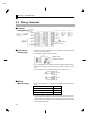
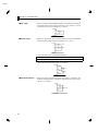
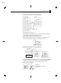
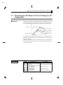
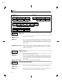
E5AN CHAPTER 5 PARAMETERS Adjustment Level Set point 0 Set point 1 The “number of multi-SP uses” parameter must be set to either “1” or “2”, and the “multi-SP uses” parameter must be set to “ON”. Set point 2 Set point 3 These parameters set the set points when the multiĆSP function is used. The values set in these parameters can be selected by operating the keys on the front panel or by event input. Function Ă• When the set point has been changed, the set value of these parameters currently set by multiĆSP is linked and changed. Ă• During temperature input, the decimal point position is dependent on the selected sensor. During analog input, the decimal point position is dependent on the setting of the decimal point position" parameter. Setting Range Set point lower limit to set point upper limit Unit EU Default 0 Setting FĂRelated parameters Number of multiĆSP uses" (advanced function setting level) (p. 5Ć28) See Event input assignment 1" (advanced function setting level) (p. 5Ć29) Event input assignment 2" (advanced function setting level) (p. 5Ć29) MultiĆSP uses" (advanced function setting level) (p. 5Ć30) PV/SP" (operation level) Input type" (operation level) (p. 5Ć5) Input type" (initial setting level) (p. 5Ć20) 5–14 E5AN Adjustment Level The “input type” parameter must be set to temperature input excluding a non-contact temperature sensor. Temperature input shift Sometimes an error between the set point and the actual temperature occurs. To offset this, a value obtained by adding an input shift value to the input is displayed as the measurement value and used for control. The entire input range is shifted by a fixed rate (1Ćpoint shift). If the input shift value is set to -1.0_C", the set point is controlled to a value obtained by subtracting 1.0_C Function from the actual temperature. Setting Range -199.9 to 999.9 Unit _C or _F Default 0.0 Setting FĂRelated parameter Input type" (initial setting level) (p. 5Ć20) See The “input type” parameter must be set to only the non-contact temperature sensor. Upper-limit temperature input shift value Lower-limit temperature input shift value Whereas the entire input range is shifted by a fixed rate (1Ćpoint shift) in the temperature input shift" parameter, the input range is shifted by two points (2Ćpoint shift) at the upper and lower limits. 2Ćpoint shift enables more accurate offset of the input range compared with 1Ćpoint shift, if the input shift values at the upper and lower limits differ. This parameter sets input shift values for each of the upper and lower limits (2Ćpoint shift) of the input range. Function Setting Range -199.9 to 999.9 Unit _C or _F Default 0.0 Setting FĂRelated parameter Input type" (initial setting level) (p. 5Ć20) See 5–15 E5AN CHAPTER 5 PARAMETERS Adjustment Level The control must be 2-PID control. Proportional band Integral time Derivative time This parameter sets the PID parameters. Note that PID is automatically set when AT and ST are executed. Proportional action : P refers to control in which the MV is proportional to the deviĆ ation (control error). Function Integral action : I gives a control action that is proportional to the time integral of the control error. With proportional control, there is norĆ mally an offset (control error). So, proportional action is used in combination with integral action. As time passes, this conĆ trol error disappears, and the set point comes to agree with the control temperature (process value). Derivative action : D gives a control action that is proportional to the time derivaĆ tive of the control error. As proportional control and integral control correct for errors in the control result, the control sysĆ tem will be late in responding to sudden changes in temperaĆ ture. Derivative action enables control that is proportional to a predicted process output to correct for future error. Setting Parameter Proportional band Setting Range 0.1 to 999.9 Unit EU Default 8.0 Integral time Derivative time 0 to 3999 0 to 3999 Second Second 233 40 FĂRelated parameter AT execute/cancel" (adjustment level) (p. 5Ć12) See 5–16 E5AN Adjustment Level The control must be either heating and cooling control and 2-PID control. Cooling coefficient If the heating and cooling characteristics of the control target greatly differ, preventing satisfacĆ tory control characteristics from being obtained by the same PID parameters, adjust the proporĆ tional band (P) at the cooling side by adding the cooling coefficient to balance control between the heating and cooling sides. In heating and cooling control, cooling side P is calculated by the following formula to set the cooling coefficient: Function Cooling side P = Cooling coefficient P (proportional operation) Setting Range Unit Default 0.01 to 99.99 None 1.00 Setting FĂRelated parameter Proportional band" (adjustment level) (p. 5Ć16) See The control system must be heating and cooling control. Dead band This parameter sets the output dead band width in a heating and cooling control system. A negaĆ tive setting sets an overlap band. This parameter sets an area in which the control output is 0" centering around the set point in a heating and cooling control system. Function Setting Range -199.9 to 999.9 Unit EU Default 0.0 Setting 5–17 E5AN CHAPTER 5 PARAMETERS Adjustment Level The control must be standard control and 2-PID control. The “integral time” parameter must be set to “0”. Manual reset value Ă• This parameter sets the required manipulated variable to remove offset during stabiĆ lization of P or PD control. Function Setting Range 0.0 to 100.0 Unit % Default 50.0 Setting FĂRelated parameters PID / ON/OFF" (initial setting level) (p. 5Ć23) Integral time" (adjustment level) (p. 5Ć16) See The control must be ON/OFF control. Hysteresis (heat) Hysteresis (cool) This parameter sets the hysteresis for ensuring stable operation at ON/OFF switching. Ă• In a standard control, use the hysteresis (heat)" parameter. The hysteresis (cool)" parameter cannot be used. Function Ă• In a heating and cooling control, the hysteresis can be set independently for heating and cooling. Use the hysteresis (heat)" parameter to set the heating side hysteresis, and use the hysteresis (cool)" parameter to set the cooling side hysteresis. Setting Range 0.1 to 999.9 Unit EU Default 1.0 Setting FĂRelated parameter PID / ON/OFF" (initial setting level) (p. 5Ć23) See 5–18 E5AN Initial Setting Level This level is for setting up the basic specifications of the E5AN. In this level, you can set the input type" parameter for selecting the sensor input to be connected to the E5AN, limit the setĆ ting range of set points or set the alarm mode. Power ON Operation level key 1 second min. key 3 seconds min. Initial setting level key No.1 display flashes. Control stop Control in progress Control stopped To move from the operation level to the initial setting level, press key for three seconds or more. Ă• The initial setting level is not displayed when initial/communications protection" is set to 2". This initial setting level can be used when initial setting/communications protection" is set to 0" or 1". Ă• The scaling upper limit", scaling lower limit" and decimal point" parameters are displayed when analog input is selected as the input type. Initial setting level Page Page ST Input type 5-20 Scaling upper limit 5-21 Scaling lower limit 5-24 Control period (heat) Control period (cool) 5-21 Decimal point 5-21 _C/_F selection 5-24 5-24 Direct/reverse operation 5-25 Alarm 1 type 5-22 Set point upper limit 5-25 Alarm 2 type 5-22 Set point lower limit 5-25 Alarm 3 type 5-22 5-25 5-23 Move to advanced function setting level 5-26 PID / ON/OFF Standard/heating and cooling 5-23 5–19 E5AN CHAPTER 5 PARAMETERS Initial Setting Level Input type Ă• This parameter sets the sensor type by a corrensponding code. Ă• When this parameter is changed, the set point upper limit is changed to the default. Function If the set point limits must be changed, set the set point upper limit" and set point lower limit" parameters (initial setting level). Ă• Set the code according to the following table. Shaded ranges indicate default settings. Platinum resistance thermometer : ": platinum resistance thermometer Pt100 Setting Thermocouple : ": K thermocouple Platinum resistance thermometer Input type Name Set Value Platinum resistance thermometer Pt100 0 -200 to 850 (_C) 1 -199.9 to 500.0 (_C) / -199.9 to 900.0 (_F) 2 0.0 to 100.0 (_C) 3 -199.9 to 500.0 (_C) / -199.9 to 900.0 (_F) 4 0.0 to 100.0 (_C) JPt100 Thermocouple input type Input Temperature Range / -300 to 1500 (_F) / 0.0 to 210.0 (_F) / 0.0 to 210.0 (_F) Input type Name Set Value Thermocouple K 0 -200 to 1300 (_C) 1 -20.0 to 500.0 (_C) / 0.0 to 900.0 (_F) 2 -100 to 850 (_C) / -100 to 1500 (_F) 3 -20 to 400.0 (_C) / 0.0 to 750.0 (_F) T 4 -200 to 400 (_C) / -300 to 700 (_F) E 5 0 to 600 (_C) / 0 to 1100 (_F) L 6 -100 to 850 (_C) / -100 to 1500 (_F) U 7 -200 to 400 (_C) / -300 to 700 (_F) N 8 -200 to 1300 (_C) / -300 to 2300 (_F) R 9 0 to 1700 (_C) / 0 to 3000 (_F) S 10 0 to 1700 (_C) / 0 to 3000 (_F) B 11 100 to 1800 (_C) / 300 to 3200 (_F) K10 to 70_C 12 0 to 90 (_C) / 0 to 190 (_F) J Non-contact temperature sensor ES1A Analog input Input Temperature Range / -300 to 2300 (_F) K60 to 120_C 13 0 to 120 (_C) / 0 to 240 (_F) K115 to 165_C 14 0 to 165 (_C) / 0 to 320 (_F) K160 to 260_C 15 0 to 260 (_C) / 0 to 500 (_F) 0 to 50mV 16 One of following ranges depending on the results of scaling: -1999 to 9999, -199.9 to 999.9, FĂRelated parameters See 5–20 _C/_F selection" Set point upper limit" Set point lower limit" (initial setting level) (p. 5Ć22) E5AN Initial Setting Level The input type must be set to analog input. Scaling upper limit Scaling lower limit Decimal point Ă• These parameters can be used when voltage input is selected as the input type. Function Ă• When voltage input is selected as the input type, scaling is carried out. Set the upper limit in the scaling upper limit" parameter and the lower limit in the scaling lower limit" parameter. Ă• The decimal point" parameter specifies the decimal point position of parameters (set point, etc.) whose unit is set to EU. Ă• Scaling upper limit, Scaling lower limit Setting Parameter Scaling upper limit Scaling lower limit Setting Range Scaling lower limit +1 to 9999 -1999 to scaling upper limit -1 Unit None None Default 100 0 Ă• Decimal point: Default is 0: 0 digits past decimal point" Set value Setting Example 0 1 0 digits past decimal point 1 digit past decimal point 1234 123.4 FĂRelated parameter Input type" (initial setting level) (p. 5Ć20) See 5–21 E5AN CHAPTER 5 PARAMETERS Initial Setting Level _C/_F selection The input type must be set to temperature input. Ă• Set the temperature input unit to either of _C" or _F". Function Setting Range Default : _C / : _F Setting FĂRelated parameter Input type" (initial setting level) (p. 5Ć20) See Set point upper limit Set point lower limit Function Ă• This parameter limits the upper and lower limits when the SP is set. The SP can be set within the range defined by the upper and lower limit set values in the set point upper limit" and set point lower limit" parameters. The existing SP settings that are out of the range are forcibly changed to one of the upper or lower limit values (whichĆ ever is closest). Ă• When the temperature input type and temperature unit have been changed, the set point upper limit and set point lower limit are forcibly changed to the upper and lower limits of the sensor. Ă• During temperature input, the decimal point position is dependent on the currently selected sensor. During analog input, it is dependent on the decimal point" parameĆ ter setting. Parameter Set point upper limit Setting Set point lower limit Setting Range Set point lower limit +1 to sensor range upper limit Platinum resistance thermometer Sensor range lower limit to set point upper limit -1 Unit EU EU EU FĂRelated parameters Input type" (p. 5Ć20) _C/_F selection" (initial setting level) (p. 5Ć22) See 5–22 Default 1300 850 -200 E5AN Initial Setting Level PID / ON/OFF Ă• This parameter selects 2ĆPID control or ON/OFF control. Ă• The AT and ST tuning functions can be used in 2ĆPID control. Function Setting Range : 2-PID / Default : ON/OFF Setting FĂRelated parameters AT execute/cancel" (p. 5Ć12) Manual reset" Hysteresis (heat)" Hysteresis (cool)" See (adjustment level) (p. 5Ć18) ST stable range" (advanced function setting level) (p. 5Ć36) Standard/heating and cooling The E5AN must support alarm 3 output. Ă• This parameter selects standard control or heating and cooling control. Function Ă• When heating and cooling control is selected, the alarm 3 output terminal ALM3" is used for cooling side output. Therefore, alarm 3 cannot be used. Setting Range : Standard / Default : Heating and cooling Setting See FĂRelated parameters MV monitor (heat)" MV monitor (cool)" (operation level) (p. 5Ć9, 10) Alarm value" (p. 5Ć7) UpperĆlimit alarm value 3" LowerĆlimit alarm value 3" (operation level) (p. 5Ć9) Hysteresis (cool)" (p.Ă5Ć18) Cooling coefficient" Dead band" (p.Ă5Ć17) (adjustment level) Control period (cool)" (initial setting level) (p. 5Ć24) Alarm 3 type" (initial setting level) (p. 5Ć25) Alarm 3 hysteresis" (p.Ă5Ć34) Alarm 3 open in alarm" (p.Ă5Ć34) (advanced function setting level) 5–23 E5AN CHAPTER 5 PARAMETERS Initial Setting Level The control must be set to temperature input, standard control and 2-PID control. ST self-tuning Ă• The ST (selfĆtuning) function executes tuning from the start of program execution to calculate PID constants matched to the control target. When the ST function is in Function operation, be sure to turn the power supply of the load connected to the control outĆ put ON simultaneously with or before starting operation of the E5AN. Parameter ST Setting Range : ST function OFF / : ST function ON Unit Default None Setting See FĂRelated parameters ST stable range" (advanced function setting level) (p. 5Ć36) Input type" (p. 5Ć20) PID / ON/OFF" (p. 5Ć23) (initial setting level) Control period (heat) The control must be set to 2-PID control. Control period (cool) Ă• This parameter sets the output period. Set the control period taking the control charĆ acteristics and the electrical life expectancy of the relay into consideration. Function Ă• In a standard control system, use the control period (heat)" parameter. The control period (cool)" parameter cannot be used. Ă• Whenever control output 1 is the current output, control period (heat)" cannot be used. Ă• In a heating and cooling control system, the control period can be set independently for heating and cooling. Use the control period (heat)" parameter to set the heating side control period, and use the control period (cool)" parameter to set the cooling side control period. Setting Parameter Setting Range Unit Default Control period (heat) Control period (cool) 1 to 99 1 to 99 Second Second 20 20 FĂRelated parameter PID / ON/OFF" (initial setting level) (p. 5Ć23) See 5–24 E5AN Initial Setting Level Direct/reverse operation Function Ă• Direct operation" refers to control where the manipulated variable is increased according to the increase in the process value. Alternatively, reverse operation" refers to control where the manipulated variable is increased according to the decrease in the process value. Setting Range : Reverse operation/ Default : Direct operation Setting Alarm 1 type The alarm 1 type must be supported. Ă• Select one of the following alarm 1 types: Deviation/Deviation range/Absolute value Function Refer to the alarm 2, 3 type list on the following page. Setting See FĂRelated parameters Alarm value 1" (operation level) (p. 5Ć7) UpperĆlimit alarm value 1" LowerĆlimit alarm value 1" (operation level) (p. 5Ć8) Standby sequence reset method" (p.Ă5Ć31) Alarm 1 open in alarm" Alarm 1 hysterĆ esis" (p. 5Ć32) (advanced function setting level) Alarm 2 type The alarm 2, 3 type must be supported. The control must be set to standard control. Alarm 3 type Ă• Select one of the following alarm 2, 3 types: Deviation/Deviation range/Absolute value Function 5–25 E5AN CHAPTER 5 PARAMETERS Initial Setting Level Set Value Setting *1 Alarm function OFF 1 Upper- and lower-limit (deviation) 5 ON OFF Upper- and lower-limit with standby sequence (deviation) ON OFF *5 6 Upper-limit with standby sequence (deviation) ON OFF 7 Lower-limit with standby sequence (deviation) ON OFF 8 ON OFF Absolute-value lower-limit 10 11 ON OFF Absolute-value upper-limit 9 X SP X ON OFF Upper- and lower-limit range (deviation) Absolute-value upper-limit with standby sequence ON OFF Absolute-value lower-limit with standby sequence ON OFF *2 SP ON OFF Lower-limit (deviation) 4 L H ON OFF Upper-limit (deviation) 3 *1 Output OFF 0 2 *1 Alarm Output Operation When X is positive When X is negative Alarm Type SP L H ON OFF ON OFF X SP X SP *3 SP L H *4 SP X SP X SP X 0 X 0 X 0 X 0 ON OFF ON OFF ON OFF ON OFF ON OFF ON OFF X SP X SP X 0 X 0 X 0 X 0 *1 : The upperĆ and lowerĆlimit values, expressed as L" and H", can be set independently for each alarm point with set values 1, 4 and 5. *2 : Set value : 1 UpperĆ and lowerĆlimit alarm Case 1 Case 2 Case 3 (Normally ON) H < 0, L < 0 L SP H L H SP SP L H H < 0, L > 0 |H| < |L| H > 0, L < 0 |H| > |L| H L SP SP H L H < 0, L > 0 |H| > |L| H > 0, L < 0 |H| < |L| *3 : Set value : 4 UpperĆ and lowerĆlimit range Case 1 Case 2 Case 3 (Normally OFF) H < 0, L < 0 L SP H L H SP SP L H H < 0, L > 0 H < 0, L > 0 H > 0, L < 0 |H| > |L| H L SP H > 0, L < 0 |H| < |L| SP H L *4 : Set value : 5 UpperĆ and lowerĆlimit alarm with standby sequence *For the above upperĆ and lowerĆlimit alarm Ć In cases 1 and 2, the alarm is normally OFF if upperĆ and lowerĆlimit values of hysteresis overlap. Ć In case 3, the alarm is normally OFF. *5 : Set value : 5 UpperĆ and lowerĆlimit alarm with standby sequence The alarm is normally OFF if upperĆ and lowerĆlimit values of hysteresis overlap. See 5–26 Ă• Alarm types are set independently for each alarm in the alarm 1 to 3 type" parameĆ ters (initial setting level). Default is 2: UpperĆlimit alarm". FĂRelated parameters Alarm value 2, 3" (operation level) (p. 5Ć7) UpperĆlimit alarm value 2, 3" LowerĆlimit alarm value 2, 3" (operation level) (p. 5Ć8, 9) Standby sequence reset method" (p.Ă5Ć31) Alarm 2, 3 open in alarm" Alarm 2, 3 hysteresis" (p. 5Ć33, 34) (advanced function setting level) E5AN Advanced Function Setting Level This level is for using the E5AN to its maximum. To move to this level, input the password (-169") in the initial setting level". To enter the password, the setting value of "initial setting/communications protection" must be set to "0". Power ON Operation level Adjustment level key Less than 1 second key 3 seconds min. key 1 second min. key No.1 display flashes. Control stops. Initial setting level key Less than 1 second key 1 second min. Communications setting level Password input set value “–169” Control in progress Advanced function setting level Control stopped Ă• The parameters in this level can be used when initial setting/communications protection" is set to 0". Ă• The move to calibration level" can be moved to by entering the password (1201"). Ă• To switch between setting levels, press the key. Ă• To change setting values, press the keys. Advanced function setting level Parameter initialize Page 5-28 Page 5-28 Event input assignment 1 5-29 Event input assignment 2 5-29 5-30 SP ramp set value MV upper limit 5-33 Alarm 2 hysteresis Number of multiĆSP uses MultiĆSP uses Alarm 2 open in alarm 5-37 MV lower limit 5-33 Alarm 3 open in alarm Alarm 3 hysteresis HBA used Page 5-37 Input digital filter 5-34 5-38 5-34 Additional PV display 5-38 5-35 Manipulated variable display 5-39 5-30 Heater burnout latch 5-35 Automatic return of display mode 5-39 Standby sequence reset method 5-31 Heater burnout hysteresis 5-35 Move to calibration level 6-2 Alarm 1 open in alarm 5-32 ST stable range Alarm 1 hysteresis 5-32 5-36 α 5-36 5–27 E5AN CHAPTER 5 PARAMETERS Advanced Function Setting Level Parameter initialize This parameter returns parameter settings to their defaults. Function ON : Initializes all parameters. OFF : Turns the E5AN OFF after returning parameter settings to their defaults. Setting Number of Multi-SP Uses The option event input unit must be mounted in the E5AN. MultiĆSP" is a function for setting set points 0 to 3 in advance, and selecting these set Function points by a combination of event inputs 1 and 2. The number of multiĆSP uses" parameter is used when the number of preset set points is 2 or 4. This parameter determines display or nonĆdisplay of the event input assignĆ ment 1" and event input assignment 2" parameters. The number of multiĆSP uses" displays which functions are assigned to event inputs 1 and 2. Setting Number of Multi-SP Uses 0 1 2 Event Input 1 Function Event Input 2 Function Set in “event input assignment 1” Multi-SP (SP 0/1 selectable) Set in “event input assignment 2” Set in “event input assignment 2” Multi-SP (SP 0/1/2/3 selectable) Ă• Default : 1 MultiĆSP can be used when the option event input unit is mounted on the E5AN, and the number of multiĆSP uses" is set to 1" or 2". Ă• When the number of multiĆSP uses is set to 1" 5–28 Event input 1 OFF Selected Set Point Set point 0 ON Set point 1 E5AN Advanced Function Setting Level Ă• When the number of multiĆSP uses is set to 2" Event input 1 Event input 2 Selected Set Point OFF ON OFF ON OFF OFF ON ON Set point 0 Set point 1 Set point 2 Set point 3 * Event input can be used when the option event input unit E53ĆAKB is mounted in the E5AN. Select event input ON/OFF while the E5AN is turned ON. Judgment of event input ON/OFF is carried out on event inputs of 50 ms or more. FĂRelated parameters Event input assignment 1" (advanced function setting level) (p. 5Ć29) See Event input assignment 2" (advanced function setting level) (p. 5Ć29) MultiĆSP uses" (advanced function setting level) (p. 5Ć30) Set point 0 to 3" (adjustment level) (p. 5Ć14) Event input assignment 1 The number of multi-SP uses must be set to “0” or “1”. Event input assignment 2 Ă• The following functions are assigned as event input 1 or event input 2: Run/stop" Function Settings Function None RUN/STOP Setting Ă• Default is " for event input assignment 1 and " for event input assignĆ ment 2. FĂRelated parameters Set point 0 to 3" (adjustment level) (p. 5Ć14) See Number of multiĆSP uses" (advanced function setting level) (p. 5Ć28) 5–29 E5AN CHAPTER 5 PARAMETERS Advanced Function Setting Level Multi-SP uses Function Setting See When the multiĆSP uses" parameter is set to ON", you can select set points 0 to 3 by operating the keys on the front panel of the controller. When the option event input unit E53ĆCNHB is mounted on the E5AN, this parameter can be used when the number of multiĆSP uses" parameter is set to 0" and multiĆSP uses" is set to ON. : Set points 0 to 3 can be selected. : Set points 0 to 3 can not be selected. Ă• Default : OFF FĂRelated parameters MultiĆSP" (operation level) (p. 5Ć5) Number of MultiĆSP uses" (advanced function setting level) (p. 5Ć28) SP ramp set value Function The “number of multi-SP uses” parameter must be set to “0” on models on which the option event input unit is not mounted. ST (self-tuning) must be set to “OFF”. Ă• This parameter specifies the change rate during SP ramp operation. Set the maxiĆ mum permissible change width per unit of time (minute) as the SP ramp set value". However, note, that when the SP ramp set value" is set to OFF", the SP ramp funcĆ tion is disabled. Ă• During temperature input, the decimal point position of the SP ramp set value is dependent on the currently selected sensor, and during analog input it is dependent on scaling. Parameter SP ramp set value Setting Range OFF, 1 to 9999 Unit EU Default OFF Setting See 5–30 FĂRelated parameters Input type" (p.Ă5Ć20) Scaling upper limit" Scaling lower limit" (p.Ă5Ć21) Decimal point" ST" (p. 5Ć24) (initial setting level) E5AN Advanced Function Setting Level Standby sequence reset method The alarm 1 to 3 type must be set to “with standby sequence.” Ă• This parameter selects the conditions for enabling reset after the standby sequence of the alarm has been canceled. Function Ă• Condition A: Control started (including power ON), and set point, alarm value (upper/lowerĆlimit alarm value) or input shift value (upper/lowerĆlimit temperature input shift value) changed Ă• Condition B: Power ON Ă• The following example shows the reset action when the alarm type is lowerĆlimit alarm with standby sequence. SP change Condition A only Alarm point (after change) Alarm hysteresis Condition A only f: Standby sequence canceled point F: Standby sequence reset point Alarm point Alarm output: Condition A Alarm output: Condition B Setting Range : Condition A / Default : Condition B Setting FĂRelated parameters Alarm 1 to 3 type" (initial setting level) (p. 5Ć25) See 5–31 E5AN CHAPTER 5 PARAMETERS Advanced Function Setting Level Alarm 1 function must be supported. Alarm 1 open in alarm Function Ă• This parameter sets the output states of alarm 1. Ă• When the E5AN is set to close in alarm," the status of the alarm output function is normally open. When set to open in alarm," the status of the alarm output is output inverted normally, or closed. The following table shows the relationship between alarm output functions, alarm output and output LCDs. Alarm Output Function ON OFF ON OFF Close in alarm Setting Open in alarm Alarm Output ON OFF OFF ON Setting Range : Close in alarm / See Output LCDs Lit Out Lit Out Default : Open in alarm FĂRelated parameters Alarm value 1" (p.Ă5Ć7) UpperĆlimit alarm value 1" LowerĆlimit alarm value 1" (p. 5Ć8)(operation level) Alarm 1 type" (p.Ă5Ć25) Standard/heating and cooling" (p.Ă5Ć23) (initial setting level) Alarm 1 hysteresis" (p.Ă5Ć32) Standby sequence reset method" (p.Ă5Ć31) (advanced function setting level) Alarm 1 function must be supported. Alarm 1 hysteresis Ă• This parameter sets the hysteresis of alarm output 1. Function Setting Range Unit Default 0.1 to 999.9 EU 0.2 Setting FĂRelated parameters See Alarm value 1" (p.Ă5Ć7) UpperĆlimit alarm value 1" LowerĆlimit alarm value 1" (p.Ă5Ć8) (operation level) Alarm 1 type" (p.Ă5Ć25) Standard/heating and cooling" (p.Ă5Ć23) (initial setting level) Alarm 1 open in alarm" (p.Ă5Ć32) Standby sequence reset method" (p.Ă5Ć31) (advanced function setting level) 5–32 E5AN Advanced Function Setting Level Alarm 2 function must be supported. Alarm 2 open in alarm Function Ă• This parameter sets the output states of alarm 2. Ă• When the E5AN is set to close in alarm," the status of the alarm output function is normally open. When set to open in alarm," the status of the alarm output function is output inverted normally closed. The following table shows the relationship between alarm output functions, alarm output and output LCDs. Alarm Output Function ON OFF ON OFF Close in alarm Setting Open in alarm Alarm Output ON OFF OFF ON Setting Range : Close in alarm / See Output LCDs Lit Out Lit Out Default : Open in alarm FĂRelated parameters Alarm value 2" (p.Ă5Ć7) UpperĆlimit alarm value 2" LowerĆlimit alarm value 2" (p.Ă5Ć8) (operation level) Alarm 2 type" (initial setting level) (p. 5Ć25) Alarm 2 hysteresis" (p.Ă5Ć33) Standby sequence reset method" (p.Ă5Ć31) (advanced function setting level) Alarm 2 function must be supported. Alarm 2 hysteresis Ă• This parameter sets the hysteresis of alarm output 2. Function Setting Range Unit Default 0.1 to 999.9 EU 0.2 Setting See FĂRelated parameters Alarm value 2" (operation level) (p. 5Ć7) UpperĆlimit alarm value 2" LowerĆlimit alarm value 2" (operation level) (p. 5Ć8) Alarm 2 type" (p. 5Ć25) (initial setting level) Alarm 2 open in alarm" (p.Ă5Ć33) Standby sequence reset method" (p.Ă5Ć31) (advanced function setting level) 5–33 E5AN CHAPTER 5 PARAMETERS Advanced Function Setting Level Alarm 3 function must be supported. Control must be set to standard control. Alarm 3 open in alarm Ă• This parameter sets the output states of alarm 3. Function Ă• When the E5AN is set to close in alarm," the status of the alarm output function is normally open. When set to open in alarm," the status of the alarm output is output inverted normally, or closed. The following table shows the relationship between alarm output functions, alarm output and output LCDs. Close in alarm Setting Open in alarm Alarm Output Function ON OFF ON OFF Alarm Output ON OFF OFF ON Setting Range : Close in alarm / See Output LCDs Lit Out Lit Out Default : Open in alarm FĂRelated parameters Alarm value 3" (p.Ă5Ć7) UpperĆlimit alarm value 3" LowerĆlimit alarm value 3" (p.Ă5Ć9)(operation level) Alarm 3 type" (p.Ă5Ć25) Standard/heating and cooling" (p.Ă5Ć23) (initial setting level) Alarm 3 hysteresis" (p.Ă5Ć34) Standby sequence reset method" (p.Ă5Ć31) (advanced function setting level) Alarm 3 function must be supported. Control must be set to standard control. Alarm 3 hysteresis Ă• This parameter sets the hysteresis of alarm output 3. Function Setting Range 0.1 to 999.9 Unit EU Default 0.2 Setting See FĂRelated parameters Alarm value 3" (operation level) (p. 5Ć7) UpperĆlimit alarm value 3" LowerĆlimit alarm value 3" (p. 5Ć9) (operation level) Alarm 3 type" (p. 5Ć25) Standard/heating and cooling" (p. 5Ć23) (initial setting level) (p.5Ć23) Alarm 3 open in alarm" (p.Ă5Ć34) Standby sequence reset method" (p.Ă5Ć31) (advanced function setting level) 5–34 E5AN Advanced Function Setting Level The option input unit E5AN-VVHVV must be mounted on the E5AN. HBA used Ă• This parameter sets use of the heater burnout alarm. Function Ă• This parameter can be used when option input unit E5ANĆVVHVV is mounted on the E5AN. Setting Range : Enabled / Default : Disabled Setting The “HBA used” parameter must be set to “ON”. Heater burnout latch Ă• When this parameter is set to ON, the heater burnout alarm is held until either of the following conditions is satisfied: Function a Heater burnout detection is set to 0.0A". b The power is turned OFF then back ON again (power is reset). Setting Range : Enabled / Default : Disabled Setting FĂRelated parameter HBA used" (advanced function setting level) (p. 5Ć35) See The “heater burnout latch” parameter must be set to OFF. Heater burnout hysteresis Ă• This parameter sets the hysteresis when HBA is detected. Function Setting Range 0.1 to 50.0 Unit A Default 0.1 Setting FĂRelated parameter HBA used" (advanced function setting level) (p. 5Ć35) See 5–35 E5AN CHAPTER 5 PARAMETERS Advanced Function Setting Level The control must be set to temperature input, standard control, PID control, and ST set to “ON”. ST stable range Ă• This parameter sets the set value for determining the conditions under which ST (selfĆtuning) occurs. This parameter cannot be used when the ST" parameter is set to OFF". Function Setting Range 0.1 to 999.9 Unit _C or _F Default 15.0 Setting FĂRelated parameters PID / ON/OFF" (initial setting level) (p. 5Ć23) Input type" (initial setting level) (p. 5Ć20) ST" (initial setting level) (p. 5Ć24) See α The control must be 2-PID control, and the “ST” parameter must be set to “OFF”. Ă• Normally, use this parameter at its default. Ă• This parameter sets 2ĆPIDĆconstant α. Function Setting Range 0.00 to 1.00 Unit None Default 0.65 Setting FĂRelated parameters See 5–36 PID / ON/OFF" (initial setting level) (p. 5Ć23) ST" (initial setting level) (p. 5Ć24) E5AN Advanced Function Setting Level MV upper limit The control must be 2-PID control, and the “ST” parameter must be set to “OFF”. MV lower limit Ă• The MV upper limit" and MV lower limit" parameters set the upper and lower limĆ Function Setting its of the manipulated variable. When the manipulated variable calculated by the E5AN exceeds the upper or lower limit value, the upper or lower limit set becomes the output level. Ă• MV upper limit The setting ranges during standard control and heating and cooling control are difĆ ferent. The manipulated variable at the cooling side during heating and cooling control is expressed as a negative value. Control Method Standard Heating and cooling Setting Range MV lower limit +0.1 to 105.0 0.0 to 105.0 Unit Default % % 105.0 105.0 Ă• MV lower limit The setting ranges during standard control and heating and cooling control are difĆ ferent. The manipulated variable at the cooling side during heating and cooling control is expressed as a negative value. Control Method Standard Heating and cooling See Setting Range -5.0 to MV upper limit -0.1 -105.0 to 0.0 Unit Default % % -5.0 -105.0 FĂRelated parameters PID / ON/OFF" (initial setting level) (p. 5Ć23) ST" (initial setting level) (p. 5Ć24) 5–37 E5AN CHAPTER 5 PARAMETERS Advanced Function Setting Level Input digital filter Ă• Sets the time constant of the input digital filter. The following figure shows the effect on data after passing through the digital filter: Function PV before passing through filter A PV after passing through filter 0.63A Time constant Time Input digital filter Setting Range 0.0 to 999.9 Unit Second Default 0.0 Setting Additional PV display Function Ă• This parameter adds the facility of displaying only the PV. It is added to the top of the operation level. It is used to give the option of displaying the PV and SP or just the PV only. Setting Range : Displayed / : Not displayed Setting 5–38 Default OFF E5AN Advanced Function Setting Level Manipulated variable display This parameter displays the manipulated variable. Function The manipulated variable is displayed when the manipulated variable monitor (heat) and (cool)" parameters are set to ON", and not displayed when these parameters are set to OFF". Setting Range : Displayed / : Not displayed Default OFF Setting Automatic return of display mode Ă• If any of the keys on the front panel for the time set by this parameter in the operaĆ tion level" and adjustment level" are not operated, the display automatically Function returns to the PV/SP display. Ă• This function is disabled (display does not change automatically) when this parameĆ ter is set to OFF". Setting Range OFF, 1 to 99 Unit Second Default OFF Setting 5–39 E5AN CHAPTER 5 PARAMETERS Communications Setting Level Communications function must be supported. Communications unit No. Baud rate Communications data length Communications stop bit Communications parity Ă• Each parameter is enabled when the power is reset. Function Ă• Match the communications specifications of the E5AN and the host computer. If a 1 : N connection is being used, ensure that the communications specifications for all devices in the system (except Communications unit No.") are the same. Parameter Setting Displayed Characters Set Value Setting Range Communications unit No. 0, 1 to 99 0 to 99 Baud rate 1.2 / 2.4 / 4.8 / 9.6 / 19.2 (kbps) 1.2 / 2.4 / 4.8 / 9.6 / 19.2 (kbps) Communications data length 7 / 8 (bit) 7 / 8 (bit) Communications stop bit 1/2 1/2 Communications parity / None / even / odd / Highlighted characters indicate defaults. FĂRelated parameters Communications writing" (adjustment level) (p. 5Ć12) See 5–40 E5AN CHAPTER 6 CALIBRATION 6 CHAPTER 6 CALIBRATION 6.1 Parameter Structure . . . . . . . . . . . . . . . . . . . 6Ć2 6.2 User Calibration . . . . . . . . . . . . . . . . . . . . . . . 6Ć3 6.3 Calibrating Thermocouples . . . . . . . . . . . . . 6Ć4 6.4 Calibrating Analog Input . . . . . . . . . . . . . . . 6Ć7 6.5 Calibrating Platinum Resistance Thermometers . . . . . . . . . . . . . . . . . . . . . . . . . 6Ć8 6.6 Checking Indication Accuracy . . . . . . . . . . . 6Ć9 6–1 E5AN CHAPTER 6 CALIBRATION 6.1 Parameter Structure Ă• To calibrate the E5AN, enter the password 1201" at the move to calĆ ibration level" parameter in the advanced function setting level". " is displayed. Ă• However, note that the move to calibration level" parameter might not be displayed when, for example, the user is calibrating the E5AN for the first time. If this happens, set the initial/communications protection" parameter in the protect level to 0" before moving to the advanced function setting level". Ă• The parameters in the calibration level are structured as follows: Advanced function setting level These parameters are automatically moved to according to the event input. Once the user has calibrated the E5AN, a dot will be displayed when the calibration level is moved to, to indicate that the E5AN has already been calibrated by the user. Dot is displayed. 6–2 E5AN User 6.2 Calibration 6.2 User Calibration The E5AN is correctly calibrated before it is shipped from the factory, and normally need not be calibrated by the user. If, however, it must be calibrated by the user, use the parameters for caliĆ brating temperature input and analog input. However, note that OMRON cannot ensure the results of calibration by the user. Also, calibration data is overwritten with the latest settings. The default calibration settings cannot be returned to after user calibration. F Calibrating input When the user calibrates the E5AN, the input type currently selected in parameters is calibrated. The following 22 input types can be calibrated. Ă• Thermocouple ą: 12 types Ă• NonĆcontact temperature sensor ą: 4 types Ă• Analog input ą: 1 type Ă• Platinum resistance thermometer ą: 5 types F Registering calibration data The new calibration data for each item is temporarily registered. It can be officially registered as calibration data only when all items have been caliĆ brated to new values. Therefore, be sure to temporarily register all items when you calibrate the E5AN. When calibration data is registered, it is registered regardless of whether or not the E5AN has been calibrated by the user. Prepare separate measuring devices and equipment for calibration. For details on how to handle measuring devices and equipment, refer to the respective instruction manuals. 6–3 E5AN CHAPTER 6 CALIBRATION 6.3 Calibrating Thermocouples Ă• Calibrate according to the type of thermocouple, thermocouple 1 group (input types 0, 2, 5, 6, 8) and thermocouple 2 group (input types 1, 3, 4, 7, 9, 10, 11, 12, 13, 14, 15). Ă• When calibrating, do not cover the bottom of the E5AN. Also, do not touch the input terminals (Nos. 17 and 18) or compensating conductor on the E5AN. F Preparations E5AN 1 STV Input power supply 2 Cold junction compensator 17 18 0_C/32_F Compensating conductor Ă• Set the cold junction compensator designed for compensation of interĆ nal thermocouples to 0_C. However, make sure that internal thermocouĆ ples are disabled (tips are open). Ă• In the above figure, STV refers to a standard DC current/voltage source. Ă• Use the compensating conductor designed for the selected thermocouĆ ple. However, note that when thermocouples R, S, E, B or a nonĆcontact temperature sensor is used, the cold junction compensator and the comĆ pensating conductor can be substituted with the cold junction compenĆ sator and the compensating conductor for thermocouple K. Connecting the Cold Junction Compensator Correct process values cannot be obtained if you touch the contact ends of the comĆ pensating conductor during calibration of a thermocouple. Accordingly, shortĆcirĆ cuit (enable) or open (disable) the tip of the thermocouple inside the cold junction compensator as shown in the figure below to create a contact or nonĆcontact state for the cold junction compensator. Cold junction compensator Cold junction compensator Short E5AN 0_C/32_F Compensating conductor 6–4 E5AN 0_C/32_F Compensating conductor Open E5AN Calibrating 6.3 Thermocouples This example describes how to calibrate the E5AN when thermocouple input is currently selected on an E5AN supporting thermocouple input. (1) Connect the power supply. (2) Connect a standard DC current/voltage source (STV), precision digiĆ tal multimeter (DMM) and contact junction compensator (e.g. zero controller as in figure) to the thermocouple input terminals, as shown in the figure below. STV DMM Leave open. 17 + 18 – Zero controller OUTPUT INPUT Compensating conductor of currently selected thermocouple Use K thermocouple compensating conductor for E, R, S and B thermocouples and non-contact temperature sensor. (3) Turn the power ON. (4) Move to the calibration level. This starts the 30Ćminute aging timer. This timer provides an approxĆ imate timer for aging. After 30 minutes, the No.2 display changes to Input type 0, 2, 5, 6, 8 0". You can advance to the next step in this procedure even if 0" is not displayed. (5) Press the key to set the E5AN to the state on the left. The No.2 display at this time displays the currently entered count value entered in Hexadecimal. Set the STV as follows: ăĂ• Input types 0, 2, 5, 6, 8 : Set to 54 mV". Input type, 1, 3, 4, 7, 9, 10, 11, 12, 13, 14, 15 Ăă• Input types 1, 3, 4, 7, 9, 10, 11, 12, 13, 14, 15: Set to 24 mV". Allow the count value on the No.2 display to fully stabilize, then press the key to temporarily register the calibration setup. 6–5 E5AN CHAPTER 6 CALIBRATION key to set the E5AN to the state on the left. (6) Press the Set STV to Ć9 mV". Allow the count value on the No.2 display to fully stabilize, then press the key to temporarily register the calibration setup. (7) Press the key. The No.2 display changes to the state on the left when the input type is 1, 3, 4, 7, 9, 10, 11, 12, 13, 14 or 15. (8) Set STV to 54 mV". Allow the count value on the No.2 display to fully stabilize, then press the key to temporarily register the calibration setup. (9) Press the key. The No.2 display changes to the state on the left when the input type is 1, 3, 4, 7, 9, 10, 11, 12, 13, 14 or 15. Set STV to Ć9 mV". (10) Allow the count value on the No.2 display to fully stabilize, then press key to temporarily register the calibration setup. the (11) Press the key to set the E5AN to the state on the left. (12) Change the wiring as follows: Open in non-connected state STV 17 – DMM 18 + Leave open. Zero controller OUTPUT INPUT Compensating conductor of currently selected thermocouple Use K thermocouple compensating conductor for E, R, S and B thermocouples. Disconnect the STV to enable the thermocouple of the cold junction compensator. When doing this, be sure to disconnect the wiring on the STV side. (13) Allow the count value on the No.2 display to fully stabilize, then press the key to temporarily register the calibration setup. (14) Press the key. The No.2 display changes to the state on the left. Note that the data to be temporarily registered is not displayed when it is not entirely prepared. key. The No.2 display changes to ". Release the key Press the and wait two seconds or press the key. This stores the temporarily registered calibration data to EEPROM. Data will not be stored to memory if you press the key with " displayed on the No.2 display. (15) The calibration mode is quit by turning the power OFF. 6–6 E5AN Calibrating 6.4 Analog Input 6.4 Calibrating Analog Input This example describes how to calibrate when 0 to 50 mV input (input type 16) is currently selected on an E5AN supporting thermocouple input. 1 E5AN Input power supply 2 - 17 STV + 18 DMM (1) Connect the power supply. (2) Connect an STV and DMM to the analog input terminals, as shown in the figure above. (3) Turn the power ON. (4) Move to the calibration level. This starts the 30Ćminute aging timer. This timer provides an approxĆ imate timer for aging. After 30 minutes, the No.2 display changes to 0". It can be advanced to the next step in this procedure even if 0" is not displayed. key to set the E5AN to the state on the left. (5) Press the The No.2 display at this time displays the currently entered count value entered in Hexadecimal. Set the STV to 54mV". (6) Allow the count value on the No.2 display to fully stabilize, then press the key to temporarily register the calibration setup. (7) Press the key to set the E5AN to the state on the left. Set STV to Ć9mV". (8) Allow the count value on the No.2 display to fully stabilize, then press the key to temporarily register the calibration setup. key. The No.2 display changes to the state on the left. (9) Press the Note that the data to be temporarily registered is not displayed when it is not entirely prepared. Press the key. The No.2 display changes to ". Release the key and wait two seconds or press the key. This stores the temporarily registered calibration data to EEPROM. Data will not be stored to memory if you press the key with " displayed on the No.2 display. (10) The calibration mode is quit by turning the power OFF. 6–7 E5AN CHAPTER 6 CALIBRATION 6.5 Calibrating Platinum Resistance Thermometers This example describes how to calibrate the E5AN when it is connected to a platinum resistance thermometer. When calibrating a platinum resistance thermometer use wires of the same thickness as those used to connect the E5AN. Input power supply 1 E5AN 2 A16 B17 B18 6-dials (1) Connect the power supply. (2) Connect a precision resistance box (called 6Ćdial" in this manual) to the platinum resistance thermometer input terminals. (3) Turn the power ON. (4) Move to the calibration level. This starts the 30Ćminute aging timer. Input type 0 Input types 1, 3 Input types 2, 4 This timer provides an approximate timer for aging. After 30 minĆ utes, the No.2 display changes to 0". You can advance to the next step in this procedure even if 0" is not displayed. (5) Press the key to display the count value for each input type. The No.2 display at this time displays the currently entered count value entered in Hexadecimal. Set the 6Ćdial as follows: Ăă• Input type 0: 390 Ω Ăă• Input type 1 or 3: Ăă• Input type 2 or 4: 280 Ω 140 Ω (6) Allow the count value on the No.2 display to fully stabilize, then press the Input type 0 Input types 1, 3 key to temporarily register the calibration setup. (7) Press the key to set the E5AN to the state on the left. Set the 6Ćdial as follows: Ăă• Input type 0: 10 Ω Ăă• Input type 1 or 3: Ăă• Input type 2 or 4: 10 Ω 100 Ω (8) Allow the count value on the No.2 display to fully stabilize, then press the Input types 2, 4 key to temporarily register the calibration setup. (9) Press the key. The No.2 display changes to the state on the left. Note that the data to be temporarily registered is not displayed when it is not entirely prepared. Press the key. The No.2 display changes to ". Release the key key. This stores the temporarily and wait two seconds or press the registered calibration data to EEPROM. Data will not be stored to memory if you press the key with " displayed on the No.2 display. (10) The calibration mode is quit by turning the power OFF. 6–8 E5AN Checking 6.6 Indication Accuracy 6.6 Checking Indication Accuracy Ă• After calibrating input, be sure to check indication accuracy to make sure that the E5AN has been correctly calibrated. Ă• Operate the E5AN in the PV/SP monitor mode. Ă• Check the indication accuracy at the upper and lower limits and midĆ point. F Thermocouple or Ă• Preparation The following figure shows the required device connection. Make sure non-contact that the E5AN and cold junction compensator are connected by a comĆ temperature pensating conductor for the thermocouple that is to be used during sensor actual operation. For the nonĆcontact temperature sensor, connect a K thermocouple, and set the input type to the K thermocouple. E5AN 1 Input power supply Cold junction compensator 2 - 17 STV + 18 Compensation conductor Ă• Operation Make sure that the cold junction compensator is at 0_C, and set STV outĆ put to the voltage equivalent to the starting power of the check value. F Analog input Ă• Preparation The following figure shows the required device connection: 1 E5AN Input power supply 2 - 17 STV + 18 Ă• Operation Set the STV to the voltage equivalent to the check value. F Platinum resistance thermometer Ă• Preparation The following figure shows the required device connection: 1 E5AN Input power supply 2 A 16 B 17 6-dials B 18 Ă• Operation Set the 6Ćdial to the resistance equivalent to the check value. 6–9 E5AN CHAPTER 6 CALIBRATION 6–10 E5AN APPENDIX APPENDIX SPECIFICATIONS . . . . . . . . . . . . . . . . . . . . . . . . . AĆ2 Ratings . . . . . . . . . . . . . . . . . . . . . . . . . . . . . . . AĆ2 Characteristics . . . . . . . . . . . . . . . . . . . . . . . . . AĆ3 CURRENT TRANSFORMER (CT) . . . . . . . . . . . AĆ4 ERROR DISPLAY . . . . . . . . . . . . . . . . . . . . . . . . . . AĆ5 PARAMETER OPERATIONS LIST . . . . . . . . . . AĆ7 SENSOR INPUT SETTING AND INDICATION RANGES . . . . . . . . . . . . . . . . . . . . . AĆ10 SETUP LEVELS DIAGRAM . . . . . . . . . . . . . . . . . AĆ11 PARAMETER FLOW . . . . . . . . . . . . . . . . . . . . . . . AĆ12 A–1 E5AN APPENDIX SPECIFICATIONS JRatings Supply voltage 100 to 240 VAC, 50/60 Hz Operating voltage range 85 to 110% of rated supply voltage Power consumption 24 VAC, 50/60 Hz/24 VDC 9 VA Sensor input 5 VA/4 W Thermocouple : K, J, T, E, L, U, N, R, S, B Platinum resistance thermometer : Pt100, JPt100 Non-contact temperature sensor : K10 to 70_C, K60 to 120_C, K115 to 165_C, K160 to 260_C Voltage input: 0 to 50 mV Control output Relay output SPST-NO, 250 VAC 5 A (resistive load), electrical life : 100,000 operations Voltage output DC 12V "15%FS, max. load current 21 mA (PNP) +15 DC 12V –20%FS, max. load current 40 mA With short circuit protection circuit. Current output DC 4-20 mA load 600 Ω max. resolution approx.2,600 Alarm output SPST-NO, 250 VAC, 3 A (resistive load), electrical life: 100,000 operations Control method 2-PID or ON/OFF control Setting method Digital setting using front panel keys Indication method 7-segment digital display and single-lighting indicator Other functions According to controller model Ambient temperature -10 to 55_C (with no condensation or icing) Ambient humidity Relative humidity 25 to 85% Storage temperature -25 to 65_C (with no condensation or icing) Altitude 2,000 m or less Recommended fuse T2A, 250 VAC, time lag, low shut–off capacity Installation environment Installation Category II, Pollution Class 2 (IEC 61010–1 compliant) * For the setting ranges for each sensor input, see page AĆ10. F HBA Max. heater current Single-phase AC 50 A Input current readout accuracy ±5%FS±1 digit max. Heater burnout alarm setting range 0.1 to 49.9 A (0.1 A units) Min. detection ON time 0.0 A : Heater burnout alarm output turns OFF. 50.0 A : Heater burnout alarm output turns ON. 190 ms *1 When the control output ON time is less than 190 ms, heater burnout detection and heater current measurement are not carried out. A–2 E5AN SPECIFICATIONS JCharacteristics Thermocouple: (±0.5% of indication value or ±1_C, whichever is greater) ±1 digit max. (*1) Indication accuracy Platinum resistance thermometer: (±0.5% of indication value or ±1_C, whichever is greater) ±1 digit max. Analog input: ±5%FS±1 digit max. CT input: ±5%FS±1 digit max. Hysteresis 0.1 to 999.9EU (in units of 0.1EU) Proportional band (P) 0.1 to 999.9EU (in units of 0.1EU) Integral time (I) 0 to 3999 (in units of 1 second) Derivative time (D) 0 to 3999 (in units of 1 second) Control period 1 to 99 (in units of 1 second) Manual reset value 0.0 to 100.0% (in units of 0.1%) Alarm setting range -1999 to 9999 (decimal point position dependent on input type) Sampling period 500 ms Insulation resistance 20 MΩ min. (by 500 VDC megger) Dielectric strength 2000 VAC 50 or 60 Hz 1min Vibration resistance 10 to 55 Hz, 10 m/s2 for 10 min. each in X, Y and Z directions Shock resistance 300 m/s2 max. 3 times each in 3 axes, 6 directions (relay: 100 m/s2) Weight Approx. 310 g Protective structure Front panel: NEMA4 for indoor use (equivalent to IP66), Rear case: IP20, terminals: IP00 Memory protection EEPROM (non-volatile memory) (number of writes: 100,000) Adapter: approx. 100g, Terminal cover : approx. 20g *1 The indication of K thermocouples in the Ć200 to 1300_C range, T and N thermocouples at a temperature of Ć100_C or less, and U and L thermocouples at any temperature is ±2_C±1 digit maximum. The indication of B thermocouples at a temperaĆ ture of 400_C or less is unrestricted. The indication of R and S thermocouples at a temperature of 200_C or less is ±3_C±1 digit maximum. A–3 E5AN APPENDIX CURRENT TRANSFORMER (CT) F Specifications Item Model Max. continuous current Dielectric strength Vibration resistance Weight Accessory Specifications E54-CT1 E54-CT3 50 A 120 A (*1) 1000 VAC (1 minute) 50 Hz 98 m/s2 Approx. 11.5 g Approx. 50 g None Armature (2) Plug (2) *1 The maximum continuous current of the E5AN is 50 A. F External dimensions 21 15 2.8 7.5 E54-CT1 3 10.5 25 φ 40 10 φ 30 E54-CT3 φ2.36 9 30 40 φ 15 j 30 A–4 E5AN ERROR DISPLAY ERROR DISPLAY When an error has occurred, the No.1 display alternately indicates error codes together with the current display item. This section describes how to check error codes on the display, and the actions you must take to remedy the problem. Input error F Meaning The input value exceeds the input indication range (when the input indication range is within -1999 (-199.9) to 9999 (999.9)). F Action Check the wiring of inputs for miswiring, disconnections, shortĆcircuits and the input type. If no abnormality is found in the wiring and input type, turn the power OFF then back ON again. If the display remains the same, the E5AN must be replaced. If the display is restored, then a probable cause may be electriĆ cal noise affecting the control system. Check for electrical noise. F Operation at error After the error occurs, the error is displayed, and control output functions turn OFF. (Current output is approx. 0 mA) Alarm outputs function as if the upper limit value has been exceeded. An error message is displayed when process value" or PV/SP" are disĆ played. Display range over F Meaning Though this is not an error, this is displayed when the process value exceeds the display range when the control range is larger than the display range (Ć1999 (Ć199.9) to 9999 (999.9)). Ă• When less than Ć1999 (Ć199.9)" Ă• When larger than 9999 (999.9)" F Action Control continues, allowing normal operation. An error message is disĆ played when process value" or PV/SP" are displayed. A–5 E5AN APPENDIX RTD input (setting range: without -199.9 to 500.0(_C) type) Themocuple input RTD input (setting range: -199.9 to 500.0(_C) type) S.Err indication cccc indication Displayed by numerical value S.Err indication Displayed by numerical value Input indication range –1999 (–199.9) S.Err indication Input indication range display range 9999 (999.9) –1999 (–199.9) display range 9999 (999.9) Analog input display range < Displayed by numerical value S.Err indication cccc indication Displayed by numerical value –1999 (–199.9) display range cccc indication S.Err indication 9999 (999.9) Input indication range Analog input display range > Displayed by numerical value S.Err indication Displayed by numerical value S.Err indication Input indication range –1999 (–199.9) display range 9999 (999.9) HB error F Meaning Internal circuits are in error. F Action First, turn the power OFF then back ON again. If the display remains the same, the E5AN must be replaced. If the display is restored, then a probĆ able cause can be electrical noise affecting the control system. Check for electrical noise. F Operation at error Control output functions and alarm output turn OFF (Current output is approx. 0 mA). An error message is displayed when process value" or PV/SP" are displayed. Memory error F Meaning Internal memory operation is in error. F Action First, turn the power OFF then back ON again. If the display remains the same, the E5AN must be replaced. If the display is restored, then a probĆ able cause can be electrical noise affecting the control system. Check for electrical noise. F Operation at error Control output and alarm output turn OFF. Current value exceeds F Meaning This error is displayed when the heater current value exceeds 55.0A". F Action Control continues, allowing normal operation. An error message is disĆ played when heater current value monitor" is displayed. A–6 E5AN PARAMETER OPERATIONS LIST PARAMETER OPERATIONS LIST Operation level Parameter Name Symbol Setting (monitor) Value Display Default Unit PV Sensor input indication range PV/SP SP lower limit to SP upper limit 0 EU Multi-SP 0 to 3 0 None Set point during SP ramp SP lower limit to SP upper limit EU Heater current value monitor 0.0 to 55.0 A Run/stop Run/stop Alarm value 1 Upper-limit alarm value 1 EU Run None -1999 to 9999 0 EU -1999 to 9999 0 EU Lower-limit alarm value 1 -1999 to 9999 0 EU Alarm value 2 -1999 to 9999 0 EU Upper-limit alarm value 2 -1999 to 9999 0 EU Lower-limit alarm value 2 -1999 to 9999 0 EU Alarm value 3 -1999 to 9999 0 EU Upper-limit alarm value 3 -1999 to 9999 0 EU Lower-limit alarm value 3 -1999 to 9999 0 EU MV monitor (heat) -5.0 to 105.0 (standard) % 0.0 to 105.0 (heating and cooling) % 0.0 to 105.0 % MV monitor (cool) Set Value , Adjustment level Parameter Name Symbol Setting (monitor) Value Display Default Unit AT execute/cancel ON, OFF , None Communications writing ON, OFF , None Heater current value monitor 0.0 to 55.0 Heater burnout detection 0.0 to 50.0 0 A Set point 0 SP lower limit to upper limit 0 EU Set point 1 SP lower limit to upper limit 0 EU Set point 2 SP lower limit to upper limit 0 EU Set point 3 SP lower limit to upper limit 0 EU Temperature input shift -199.9 to 999.9 0.0 _C or _F Upper-limit temperature input shift value -199.9 to 999.9 0.0 _C or _F Lower-limit temperature input shift value -199.9 to 999.9 0.0 _C or _F Proportional band 0.1 to 999.9 8.0 EU Integral time 0 to 3999 233 Second Derivative time 0 to 3999 40 Second Cooling coefficient 0.01 to 99.99 1.00 None Dead band -199.9 to 999.9 0.0 EU Manual reset value 0.0 to 100.0 50.0 % Hysteresis (heat) 0.1 to 999.9 1.0 EU Hysteresis (cool) 0.1 to 999.9 1.0 EU Set Value A A–7 E5AN APPENDIX Initial Setting Level Parameter Name Input type * Symbol Setting (monitor) Value Display Default Unit Platinum resistance thermometer 0 : Pt100 1 : Pt100 2 : Pt100 3 : JPt100 4 : JPt100 0 None Thermocouple 0:K 1:K 2:J 3:J 4:T 5:E 6:L 7:U 8:N 9:R 10 : S 11 : B 0 None Non-contact 12 : K10 to 70_C temperature 13 : K60 to 120_C sensor 14 : K115 to 165_C 15 : K160 to 260_C Analog input 16 : 0 to 50mA Scaling upper limit Scaling lower limit +1 to 9999 100 None Scaling lower limit -1999 to scaling upper limit -1 0 None Decimal point 0,1 0 None Temperature unit _C, _F _C None Set point upper limit SP lower limit +1 to input range lower value (temperature) 1300 EU SP lower limit +1 to scaling upper limit (analog) 1300 EU Input range lower limit to SP upper limit -1 (temperature) -200 EU Scaling lower limit to SP upper limit -1 (analog) -200 EU ON/OFF None Standard None ON None Set point lower limit PID / ON/OFF 2-PID, ON/OFF Standard/heating and cooling Standard, heating and cooling ST ON, OFF Control period (heat) , , , , 1 to 99 20 Second Control period (cool) 1 to 99 20 Second Direct/reverse operation Direct operation, reverse operation Reverse operation None Alarm 1 type 0: 1: 2: 3: 4: 5: Alarm function OFF Upper- and lower-limit alarm Upper-limit alarm Lower-limit alarm Upper- and lower-limit range Upper- and lower-limit alarm with standby sequence 6: Upper-limit alarm with standby sequence 7: Lower-limit alarm with standby sequence 8: Absolute-value upper-limit alarm 9: Absolute-value lower-limit alarm 10: Absolute-value upper-limit alarm with standby sequence 11: Absolute-value lower-limit alarm with standby sequence 2 None Alarm 2 type Same as alarm 1 type 2 None Alarm 3 type Same as alarm 1 type 2 None Move to advanced function setting level -1999 to 9999 0 None A–8 , Set Value E5AN PARAMETER OPERATIONS LIST Advanced function setting level Parameter Name Symbol Setting (monitor) Value Parameter initialize ON, OFF Number of multi-SP uses Event input assignment 1 Display Default Unit OFF None 0 to 2 1 None None, run/stop , None None Event input assignment 2 None, run/stop , RUN/STOP None Multi-SP uses ON, OFF OFF None SP ramp set value OFF, 1 to 9999 OFF EU Standby sequence reset method Condition A, Condition B Condition A None Alarm 1 open in alarm Open in alarm/Close in alarm Open in alarm None Alarm 1 hysteresis 0.1 to 999.9 0.2 EU Alarm 2 open in alarm Open in alarm/Close in alarm Open in alarm None Alarm 2 hysteresis 0.1 to 999.9 0.2 EU Alarm 3 open in alarm Open in alarm/Close in alarm Open in alarm None Alarm 3 hysteresis 0.1 to 999.9 0.2 EU HBA used ON, OFF , ON None Heater burnout latch ON, OFF , OFF None Heater burnout hysteresis 0.1 to 50.0 0.1 A ST stable range 0.1 to 999.9 15.0 _C or _F α 0.00 to 1.00 0.65 None MV upper limit MV lower limit +0.1 to 105.0 (standard) 105.0 % 0.0 to 105.0 (heating and cooling) 105.0 % -5.0 to MV upper limit -0.1 (standard) -5.0 % -105.0 to 0.0 (heating and cooling) -105.0 % Input digital filter 0.1 to 999.9 0.0 Second Additional PV display ON, OFF , OFF None Manipulated variable display ON, OFF , OFF None Automatic return of display mode OFF, 1 to 9999 OFF Second Move to calibration level -1999 to 9999 0 None MV lower limit , , , to , , , , , to Set Value Protect level Parameter Name Symbol Setting (monitor) Value Display Default Unit Operation/adjustment protection 0 to 3 0 None Initial setting/ communications protection 0 to 2 1 None Setup change protection ON, OFF OFF None , Set Value Communications Setting Level Parameter Name Symbol Setting (monitor) Value Communication unit No. 0 to 99 Baud rate 1.2, 2.4, 4.8, 9.6, 19.2 Data bit Stop bit Parity None, Even, Odd Display Default Unit 1 None 9.6 kbps 7, 8 7 bit 1, 2 2 bit Even None . , . , . , . , , , . Set Value A–9 E5AN APPENDIX SENSOR INPUT SETTING AND INDICATION RANGES Input type Platinum resistance thermometer input type Platinum resistance thermometer Pt100 JPt100 Input type Thermocouple input type Specifica- Set tions Value Thermocouple Input Temperature Range 0 -200 to 850 (_C) 1 -199.9 to 500.0 (_C) / -199.9 to 900.0 (_F) -199.9 to 520 (_C) / -199.9 to 940 (_F) 2 0.0 to 100.0 (_C) -20 to 120 (_C) 3 -199.9 to 500.0 (_C) / -199.9 to 900.0 (_F) -199.9 to 520 (_C) / -199.9 to 940 (_F) 4 0.0 to 100.0 (_C) -20 to 120 (_C) Specifica- Set tions Value K J / -300 to 1500 (_F) Input Indication Range / 0.0 to 210.0 (_F) / 0.0 to 210.0 (_F) Input Temperature Range / -300 to 2300 (_F) -200 to 870 (_C) / -40 to 250 (_F) / -40 to 250 (_F) Input Indication Range 0 -200 to 1300 (_C) -220 to 1320 (_C) / -340 to 2340 (_F) 1 -20.0 to 500.0 (_C) / 0.0 to 900.0 (_F) -40 to 520 (_C) / -40 to 940 (_F) 2 -100 to 850 (_C) -120 to 870 (_C) / -140 to 1540 (_F) / -100 to 1500 (_F) 3 -20.0 to 400.0 (_C) / 0.0 to 750.0 (_F) -40 to 420 (_C) / -40 to 790 (_F) T 4 -200 to 400 (_C) / -300 to 700 (_F) -220 to 420 (_C) / -340 to 740 (_F) E 5 0 to 600 (_C) / 0 to 1100 (_F) -20 to 620 (_C) / -40 to 1140 (_F) L 6 -100 to 850 (_C) / -100 to 1500 (_F) -120 to 870 (_C) / -140 to 1540 (_F) U 7 -200 to 400 (_C) / -300 to 700 (_F) -220 to 420 (_C) / -340 to 740 (_F) N 8 -200 to 1300 (_C) / -300 to 2300 (_F) -220 to 1320 (_C) / -340 to 2340 (_F) R 9 0 to 1700 (_C) / 0 to 3000 (_F) -20 to 1720 (_C) / -40 to 3040 (_F) S 10 0 to 1700 (_C) / 0 to 3000 (_F) -20 to 1720 (_C) / -40 to 3040 (_F) B 11 100 to 1800 (_C) / 300 to 3200 (_F) 0 to 1820 (_C) / 0 to 3240 (_F) Non-contact K10 to 70_C temperature K60 to 120_C sensor ES1A K115 to 165_C 12 0 to 90 (_C) / 0 to 190 (_F) -20 to 130 (_C) / -40 to 270 (_F) 13 0 to 120 (_C) / 0 to 240 (_F) -20 to 160 (_C ) / -40 to 320 (_F) 14 0 to 165 (_C) / 0 to 320 (_F) -20 to 205 (_C) / -40 to 400 (_F) K160 to 260_C 15 0 to 260 (_C) / 0 to 500 (_F) -20 to 300 (_C) / -40 to 580 (_F) 0 to 50mV 16 One of following ranges depending on the -5 to 105% of the setting range results of scaling: -1999 to 9999, -199.9 to (However, -1999 to 9999 or -199.9 to 999.9 is displayed) 999.9 Analog input Ă• O" is the default for both input types. Ă• The applicable standards for each of the above input ranges are as follows: K, J, T, E, N, R, S, B : JIS C1602Ć1995, IEC 584Ć1 L : FeĆCuNi, DIN 43710Ć1985 U : CuĆCuNi, DIN 43710Ć1985 JPt100 : JIS C 1604Ć1989, JIS C 1606Ć1989 Pt100 : JIS C 1604Ć1997 IEC 751 A–10 / -340 to 1540 (_F) E5AN SETUP LEVELS DIAGRAM SETUP LEVELS DIAGRAM The following diagram shows an overview of the setup levels on the E5AN. To move to the advanced function setting level and calibration level, you must enter passwords. Some parameters are not displayed depending on the protect level setting and the conditions of use. Control stops when you move from the operation level to the initial setting level. Power ON Operation level Adjustment level key Less than 1 second + key 1 second min. key The PV display flashes after one second. key key 1 second min. 3 seconds min. Control stops. Initial setting level key Less than 1 second key 1 second min. Communications setting level Protect level Password input set value “-169” Advanced function setting level Password input set value “1201” Calibration level Control in progress Control stopped A–11 E5AN APPENDIX PARAMETER FLOW Ă• If you press the mode key at the last parameter in each level, you return to the top parameter in that level. Initial setting level Advanced function setting level Parameter initialize Input type Scaling upper limit 0 to 50 mV Number of multiĆSP uses Select 2 or 4 SPs. HBA used Event input assignment 1 Set multi-SP and run/stop input. Heater burnout latch Event input assignment 2 Heater burnout hysterĆ esis Decimal point Number of digits displayed past decimal point MultiĆSP uses ST stable range _C/_F selection ON/OFF Scaling lower limit Latch after HBA detection Set the deviation. Limit the set point. SP ramp set value Change rate during SP ramp α Standby sequence reset method Reset conditions after standby sequence is canceled. MV upper limit Limited to MV calculation value Set point lower limit Alarm 1 open in alarm Set the alarm output 1 ON/OFF states. MV lower limit PID / ON/OFF Alarm 1 hysteresis Input digital filter Set the time constant in seconds. Standard/heating and cooling Alarm 2 open in alarm Set the alarm output 2 ON/OFF states. Additional PV display Displayed first in the operation level. ST Alarm 2 hysteresis Manipulated variable display Control period (heat) Set point upper limit Advanced PID parameter Select the control system. Self-tuning Set the pulse output cycle. Alarm 3 open in alarm Set the alarm output 3 ON/OFF states. Alarm 3 hysteresis Automatic return of display mode Automatic return to operation level when the keys on the front panel are operated. Move to calibration level Control period (cool) Direct/reverse operation Control the manipulated variable according to the increase/decrease in the PV. Alarm 1 type Select the alarm mode. Alarm 2 type Select the alarm mode. Movement between levels is made according to the password setting. A–12 Alarm 3 type Select the alarm mode. Move to advanced function setting level E5AN PARAMETER FLOW Power ON Adjustment level Operation level PV Add in the “additional PV display” parameter. AT execute/cancel PV/SP Alarm value 2 MultiĆSP Select SP. UpperĆlimit alarm value 2 Set either of these parameters. Communications writing Enable or disable writing by communications. Heater current value monitor Set point during SP ramp LowerĆlimit alarm value 2 Heater burnout detection Heater current value monitor Current value monitor of HBA Alarm value 3 Set point 0 Set either of these parameters. UpperĆlimit alarm value 3 Alarm value 1 LowerĆlimit alarm value 3 Set point 2 MV monitor (heat) Set point 3 MV monitor (cool) Temperature input shift Set either of these parameters. LowerĆlimit alarm value 1 HBA function Set points used by multi-SP Set point 1 Run/stop UpperĆlimit alarm value 1 Auto-tuning 1-point shift UpperĆlimit temperaĆ ture input shift value 2-point shift LowerĆlimit temperaĆ ture input shift value Proportional band P Communications setting level Communication unit No. Baud rate Data bit Stop bit Parity Communications setup on other party personal computer is different. Protect level Operation/adjustment protection Restricts display and modification of menus in the operation and adjustment levels. Initial setting/communications protection Restricts display and modification of menus in the initial setup, operation level and adjustment levels. Setting change protection Protects changes to setups by operation of the front panel keys. Integral time I PID settings Derivative time D Cooling coefficient Dead band Used in heating and cooling control Manual reset value Clear the offset during stabilization of P or PD control. Hysteresis (heat) Set hysteresis. Hysteresis (cool) A–13 E5AN APPENDIX A–14 E5AN INDEX (down) key . . . . . . . . . . . . . . . . . . . . . . . (level) key . . . . . . . . . . . . . . . . . . . . . . . . + key combination . . . . . . . . . . . (mode) key . . . . . . . . . . . . . . . . . . . . . . . (up) key . . . . . . . . . . . . . . . . . . . . . . . . . . 1Ć3 1Ć3 1Ć3 1Ć3 1Ć3 Characteristics . . . . . . . . . . . . . . . . . . . . . . AĆ3 Checking indication accuracy . . . . . . . . . . . 6Ć9 Close in alarm/open in alarm . . . . . . . . . . . 4Ć7 Communications . . . . . . . . . . . . . . . . . . . . . . 2Ć7 Communications data length . . . . . . . . . . 5Ć40 Communications function . . . . . . . . . . 1Ć5, 1Ć9 Communications parity . . . . . . . . . . . . . . . 5Ć40 Communications setting level . . . . . . . . . . . . . . . . . . . . . . . . . . . . . 1Ć7, 5Ć40, AĆ9 Communications stop bit . . . . . . . . . . . . . 5Ć40 Communications unit No. . . . . . . . . . . . . . 5Ć40 Connecting the cold junction compensator . . . . . . . . . . . . . . . . . . . . . . . . . . 6Ć4 Control adjustment . . . . . . . . . . . . . . . . . . . 1Ć5 Control output . . . . . . . . . . . . . . . . . . . . . . . . 1Ć5 Control output 1 . . . . . . . . . . . . . . . . . . . . . . 2Ć6 Control period . . . . . . . . . . . . . . . . . . . . . . . . 3Ć7 Control period (cool) . . . . . . . . . . . . . . . . . . 3Ć7 Control period (heat) . . . . . . . . . . . . . . . . . . 3Ć7 Cooling coefficient . . . . . . . . . 4Ć10, 4Ć11, 5Ć17 CT input . . . . . . . . . . . . . . . . . . . . . . . . . . . . . 2Ć7 Current transformer (CT) . . . . . . . . . . . . . AĆ4 Numbers 1Ćpoint shift . . . . . . . . . . . . . . . . . . . . . . . . . . 4Ć2 1Ćpoint shift method . . . . . . . . . . . . . . . . . . . 4Ć4 2ĆPID control . . . . . . . . . . . . . . . . . . . . 3Ć6, 3Ć10 2Ćpoint shift . . . . . . . . . . . . . . . . . . . . . . . . . . 4Ć3 2Ćpoint shift method . . . . . . . . . . . . . . . . . . . 4Ć4 3Ćposition control . . . . . . . . . . . . . . . . . . . . 3Ć10 A α . . . . . . . . . . . . . . . . . . . . . . . . . . . . . . . . . . . 5Ć36 A.T. (AutoĆtuning) . . . . . . . . . . . . . . . . . . . 3Ć12 Additional PV display . . . . . . . . . . . . . . . . 5Ć38 Adjustment level . . . . . . . . . . . . . 1Ć7, 5Ć11, AĆ7 Advanced function setting level . . . . . . . . . . . . . . . . . . . . . . . . . . . . . 1Ć7, 5Ć27, AĆ9 Alarm 1 hysteresis . . . . . . . . . . . . . . . . . . . 5Ć32 Alarm 1 open in alarm . . . . . . . . . . . . . . . . 5Ć32 Alarm 1 type . . . . . . . . . . . . . . . 5Ć8, 5Ć25, 5Ć31 Alarm 2 hysteresis . . . . . . . . . . . . . . . . . . . 5Ć33 Alarm 2 open in alarm . . . . . . . . . . . . . . . . 5Ć33 Alarm 2 type . . . . . . . . . . . . . . . . . . . . . . . . 5Ć25 Alarm 3 hysteresis . . . . . . . . . . . . . . . . . . . 5Ć34 Alarm 3 open in alarm . . . . . . . . . . . . . . . . 5Ć34 Alarm 3 type . . . . . . . . . . . . . . . . . . . . . . . . 5Ć25 Alarm hysteresis . . . . . . . . . . . . . . . . . . . . . . 4Ć6 Alarm output/Control output 2 . . . . . . . . . 2Ć6 Alarm outputs . . . . . . . . . . . . . . . . . . . . . . . 3Ć17 Alarm type . . . . . . . . . . . . . . . . . . . . . . . . . . 3Ć17 Alarm value . . . . . . . . . . . . . . . . . . . . . . . . . 3Ć18 Alarm value 1 . . . . . . . . . . . . . . . . . . . . . . . . 5Ć7 Alarm value 2 . . . . . . . . . . . . . . . . . . . . . . . . 5Ć7 Alarm value 3 . . . . . . . . . . . . . . . . . . . . . . . . 5Ć7 Analog input . . . . . . . . . . . . . . . . . 1Ć5, 4Ć8, 6Ć9 Analog input (voltage input) . . . . . . 4Ć8, 5Ć21 AT (AutoĆtuning) . . . . . . . . . . . . . . . . . . . . 5Ć11 AT execute/cancel . . . . . . . . . . . . . . . . . . . . 3Ć12 Automatic return of display mode . . . . . . 5Ć39 C Calibrating analog input . . . . . . . . . . . . . . . Calibrating input . . . . . . . . . . . . . . . . . . . . . Calibrating platinum resistance thermometer . . . . . . . . . . . . . . . . . . . . . . . . . Calibrating thermocouples . . . . . . . . . . . . . Calibration level . . . . . . . . . . . . . . . . . . . . . . Changing the SP . . . . . . . . . . . . . . . . . . . . . . 6Ć7 6Ć3 6Ć8 6Ć4 1Ć7 3Ć9 D E F H Dead band . . . . . . . . . . . . . . . . . 4Ć10, 4Ć11, 5Ć17 Decimal point . . . . . 5Ć5, 5Ć7, 5Ć8, 5Ć14, 5Ć19, 5Ć21, 5Ć22, 5Ć30 Derivative time . . 3Ć12, 3Ć15, 5Ć11, 5Ć12, 5Ć16 Description . . . . . . . . . . . . . . . . . . . . . . . . . . 3Ć12 Determining PID constants (AT, ST, manual setup) . . . . . . . . . . . . . . . . 3Ć12 Dimensions . . . . . . . . . . . . . . . . . . . . . . . . . . 2Ć2 Direct/reverse operation . . . . . . . . . . 3Ć7, 5Ć25 Display . . . . . . . . . . . . . . . . . . . . . . . . . . . . . . 1Ć2 Draw out . . . . . . . . . . . . . . . . . . . . . . . . . . . . . 2Ć4 Error display . . . . . . . . . . . . . . . . . . . . . . . . AĆ5 Event input . . . . 1Ć5, 2Ć7, 4Ć12, 5Ć5, 5Ć7, 5Ć28 Example of 2Ćpoint temperature input shift . . . . . . . . . . . . . . . . . . . . . . . . . . . . . . . . . . . . . . 4Ć5 Executing ON/OFF control . . . . . . . . . . . 3Ć10 Executing run/ stop control . . . . . . . . . . . 4Ć14 Executing the SP ramp function (limiting the SP change rate) . . . . . . . . . . 4Ć17 External dimensions . . . . . . . . . . . . . . . . . AĆ4 Externally setting the SP . . . . . . . . . . . . . 4Ć12 Fixing settings . . . . . . . . . . . . . . . . . . . . . . . . 1Ć8 Front panel . . . . . . . . . . . . . . . . . . . . . . . . . . 1Ć2 HBA . . . . . . . . . . . . . . . . . . . . . . . . . . . . . 1Ć5, AĆ2 HBA detection . . . . . . . . . . . . . . . . . . . . . . . 3Ć19 Heater burnout alarm (HBA) . . . . . . . . . . 3Ć19 Heater burnout detection . . . . . . . . 3Ć20, 5Ć13 Heater burnout latch . . . . . . . . . . . . . . . . . 5Ć35 E5AN INDEX Heater current value monitor . . . . . . . . . 5Ć13 Heating and cooling control . . . . . . . . . . . 4Ć10 How setup levels are configured and operating the keys on the front panel . . . . 1Ć6 How to calculate detection current values . . . . . . . . . . . . . . . . . . . . . . . 3Ć21 How to calculate input shift values (2Ćpoint shift) . . . . . . . . . . . . . . . . . . . . . . . . . 4Ć3 How to use keys . . . . . . . . . . . . . . . . . . . . . . . 1Ć3 Hysteresis . . . . . . . . . . . . . . . . . . . . . . . . . . . 3Ć10 Hysteresis (cool) . . . . . . . . . . . . . . . . . . . . . 5Ć18 Hysteresis (heat) . . . . . . . . . . . . . . . . . . . . . 5Ć18 Operation level . . . . . . . . . . . 1Ć7, 3Ć9, 3Ć11, 5Ć4, 5Ć11, 5Ć19, AĆ7 Operation/adjustment protection . . . . . . 4Ć20 P I I/O configuration . . . . . . . . . . . . . . . . . . . . . 1Ć4 Initial setting level . . . . . . . . . . . 1Ć7, 5Ć19, AĆ8 Initial setting/ communications protection . . . . . . . . . . . . . . . . . . . . . . . . . . . 4Ć20 Initial setup examples . . . . . . . . . . . . . . . . . 3Ć2 Initial/communications protection . . . . . 5Ć19 Input digital filter . . . . . . . . . . . . . . . . . . . . 5Ć38 Input error . . . . . . . . . . . . . . . . . . . . . . . . . . AĆ5 Input sensor types . . . . . . . . . . . . . . . . . . . . 1Ć5 Input type . . . . . . . 3Ć4, 5Ć19, 5Ć20, 5Ć21, AĆ10 Installation . . . . . . . . . . . . . . . . . . . . . . . . . . . 2Ć2 Integral time . . . . . . . . . . . . . . . . . . . . . . . . 3Ć12 K Key protect . . . . . . . . . . . . . . . . . . . . . . . . . . 4Ć20 L LowerĆlimit temperature input shift value . . . . . . . . . . . . . . . . . . . . . . . . . . . 5Ć15 M Manipulated variable display . . . . . . . . . . 5Ć39 Manual reset value . . . . . . . . . . . . . . . . . . . 5Ć18 Manual setup . . . . . . . . . . . . . . . . . . . . . . . . 3Ć15 Mounting . . . . . . . . . . . . . . . . . . . . . . . . . . . . 2Ć3 MultiĆSP . . . . . . . . . . . . . . . . . . . . . . . . . . . . 4Ć12 MultiĆSP (set point 0 to 3) . . . . . . . . . . . . . 5Ć5 MV lower limit . . . . . . . . . . . . . . . . . . . . . . 5Ć37 MV monitor (cool) . . . . . . . . . . . . . . . . . . . 5Ć10 MV monitor (heat) . . . . . . . . . . . . . . . . . . . . 5Ć9 MV upper limit . . . . . . . . . . . . . . . . . . . . . . 5Ć37 N Names of parts . . . . . . . . . . . . . . . . . . . . . . . 1Ć2 No.1 display . . . . . . . . . . . . . . . . . . . . . . . . . . 1Ć2 No.2 display . . . . . . . . . . . . . . . . . . . . . . . . . . 1Ć2 Number of multiĆSP uses . . . 4Ć12, 4Ć13, 5Ć28 O ON/OFF control . . . . . . . . . . . . 3Ć6, 3Ć10, 3Ć11 Operation indicators . . . . . . . . . . . . . . . . . . 1Ć2 R Panel cutout . . . . . . . . . . . . . . . . . . . . . . . . . . 2Ć2 Parameter flow . . . . . . . . . . . . . . . . . . . . . AĆ12 Parameter initialize . . . . . . . . . . . . . . . . . . 5Ć28 Parameter operation list . . . . . . . . . . . . . . AĆ7 PID / ON/OFF . . . . . . . . . . . . . . . . . . . . . . . 5Ć23 PID constants . . . . . . . . . . . . . . . . . . . . . . . 3Ć12 Power supply . . . . . . . . . . . . . . . . . . . . . . . . . 2Ć5 Precautions when wiring . . . . . . . . . . . . . . 2Ć5 Proportional band . . . . 3Ć12, 5Ć11, 5Ć12, 5Ć16 Proportional operation . . . . . . . . . . . . . . . 3Ć15 Protect level . . . . . . . . . . . . . . . . . . 1Ć7, 5Ć3, AĆ9 PV/SP . . . . . . . . . . . . . . . . . . 3Ć9, 5Ć5, 5Ć6, 5Ć39 Ratings . . . . . . . . . . . . . . . . . . . . . . . . . . . . . AĆ2 Registering calibration data . . . . . . . . . . . . 6Ć3 Restrictions during SP ramp operation . . . . . . . . . . . . . . . . . . . . . . . . . . . 4Ć18 RSĆ485 . . . . . . . . . . . . . . . . . . . . . . . . . . . . . . . 2Ć8 Run/Stop . . . . . . . . . . . . . . . . . . . . . . . . . . . . . 5Ć7 S Scaling . . . . . . . . . . . . . . . . . . . . . . . . . . . . . . 5Ć21 Scaling lower limit . . . . . . . . . . . . . . 5Ć19, 5Ć21 Scaling upper limit . . . . . . . . . . . . . . 5Ć19, 5Ć21 Selecting _C/_F . . . . . . . . . . . . . . . . . . . . . . . 3Ć5 Selecting parameters . . . . . . . . . . . . . . . . . . 1Ć8 Selecting PID control or ON/OFF control . . . . . . . . . . . . . . . . . . . . . . 3Ć6 Sensor input setting and indication ranges . . . . . . . . . . . . . . . . . . . AĆ10 Set point . . . . . . . . . . . . . . . . . . . . . . . . . . . . . 3Ć9 Set point 0 . . . . . . . . . . . . . . . . . . . . . . . . . . 5Ć14 Set point 1 . . . . . . . . . . . . . . . . . . . . . . . . . . 5Ć14 Set point 2 . . . . . . . . . . . . . . . . . . . . . . . . . . 5Ć14 Set point 3 . . . . . . . . . . . . . . . . . . . . . . . . . . 5Ć14 Set point during SP ramp . . . . . . . . . 4Ć17, 5Ć6 Set point limitter . . . . . . . . . . . . . . . . . . . . 4Ć15 Setting change protection . . . . . . . . . . . . . 4Ć20 Setting heating and cooling control . . . . 4Ć11 Setting output specifications . . . . . . . . . . . 3Ć7 Setting scaling upper and lower limits (analog input) . . . . . . . . . . . . . . . . . . . . . . . . 4Ć8 Setting the input type . . . . . . . . . . . . . . . . . 3Ć4 Setting the PID / ON/OFF parameter . . 3Ć11 Setting the set point lower limit . . . . . . . 4Ć16 Setting the set point upper limit . . . . . . . 4Ć16 Setting the SP . . . . . . . . . . . . . . . . . . . . . . . . 3Ć9 Setting the SP upper and lower limit values . . . . . . . . . . . . . . . . . . . . 4Ć15 E5AN INDEX Setting the upper and lower limits . . . . . . 5Ć8 Setting up communications data . . . . . . . . 1Ć9 Setup levels diagram . . . . . . . . . . . . . . . . AĆ11 Shifting input values . . . . . . . . . . . . . . . . . . 4Ć2 SP ramp . . . . . . . . . . . . . . . . . . . . . . . . . . . . 4Ć17 SP ramp set value . . . . . . . . . . . . . . . . . . . . 5Ć30 Specifications . . . . . . . . . . . . . . . . . . . . AĆ2, AĆ4 ST (selfĆtuning) . . . . . . . . . . . . 3Ć13, 5Ć24, 5Ć36 ST stable range . . . . . . . . . . . . . . . . . 3Ć14, 5Ć36 ST start conditions . . . . . . . . . . . . . . . . . . . 3Ć14 Standby sequence . . . . . . . . . . . . . . . . 4Ć6, 5Ć31 Standby sequence reset method . . . . . . . . 5Ć31 Stop . . . . . . . . . . . . . . . . . . . . . . . . . . . . . . . . . 5Ć7 Summary of alarm operations . . . . . . . . . . 4Ć7 T Temperature input . . . . . . . . . . . . . . . . . . . . 1Ć5 Temperature input shift . . . . . . . . . . 4Ć5, 5Ć15 Temperature unit . . . . . . . . . . . . . . . . . 1Ć3, 3Ć5 Terminal arrangement . . . . . . . . . . . . . . . . 2Ć5 To select set points (0/1/2/3) . . . . . . . . . . . 4Ć13 U UpperĆlimit temperature input shift value . . . . . . . . . . . . . . . . . . . . . 5Ć15 User calibration . . . . . . . . . . . . . . . . . . . . . . 6Ć3 W Wiring . . . . . . . . . . . . . . . . . . . . . . . . . . . . . . . 2Ć5 E5AN INDEX E5AN Revision History A manual revision code appears as a suffix to the catalog number on the front cover of the manual. Cat. No. H112ĆE1Ć1 Revision code The following table outlines the changes made to the manual during each revision. Page numbers refer to previous version. Revision code 1 Data September 1999 Revised content Original production