1
RF Concepts
Alpha 4500A Series
Radio-Frequency Power Meter
User Manual
rfconcepts.com
Document Issue 1.0
December 2014
Alpha 4500A Series RF Power Meter User Manual
RF Concepts LLC
Alpha 4500A Series RF Power Meter User
Manual
RF Concepts LLC
634 S Sunset St
Longmont CO 80501
303-473-9232
Prepared for RF Concepts by MH/GP/NG/LW.
To reach technical support or obtain copies of this document, go to
rfconcepts.com.
Copyright © 2014 RF Concepts LLC. All rights reserved. Specifications
subject to change without notice.
IMPORTANT
!
FCC Notice
This equipment has been tested and found to comply with the limits for a
Class B digital device, pursuant to part 15 of the FCC Rules. These limits
are designed to provide reasonable protection against harmful
interference in a residential installation. This equipment generates, uses,
and can radiate radio frequency energy and, if not installed and used in
accordance with the instructions, may cause harmful interference to radio
communications. However, there is no guarantee that interference will
not occur in a particular installation. If this equipment does cause harmful
interference to radio or television reception, which can be determined by
turning the equipment off and on, the user is encouraged to try to correct
the interference by one or more of the following measures:
• Reorient or relocate the receiving antenna.
• Increase the separation between the equipment and receiver.
• Connect the equipment into an outlet on a circuit different from that
to which the receiver is connected.
• Consult the dealer or an experienced radio/TV technician for help.
Changes or modifications to this device not expressly approved by the
Manufacturer could void the user’s authority to operate this equipment.
Page ii
Document Issue 1.0
December 2014
Contents
Contents
1. Introduction . . . . . . . . . . . . . . . . . . . . . . . . . . . . . . . . . . . . 1-1
1.1 Product Capabilities 1-1
1.2 Theory of Operation 1-5
1.3 Product Safety 1-7
1.4 Product Warranty 1-7
1.5 Product Assistance 1-8
1.6 Product Specifications 1-8
2. Power-Meter Components . . . . . . . . . . . . . . . . . . . . . . . . . . . . 2-1
2.1 (Models 4510A/4520A) Analog Meter and Digital LED Display 2-2
2.2 (Models 4510A/4520A) Control Switches 2-3
2.3 SoftMeter Software 2-4
2.4 Rear-Panel Connectors 2-5
3. Setting Up the Power Meter . . . . . . . . . . . . . . . . . . . . . . . . . . . 3-1
3.1 Position the Meter 3-1
3.2 (Optional) Set Up the Host PC and SoftMeter Software 3-2
3.3 Connect the Cables 3-3
3.4 (SoftMeter Users) Configure the PC’s USB COM Port 3-5
3.5 (Optional) Change the RF Coaxial Connectors 3-5
4. Operating the Power Meter . . . . . . . . . . . . . . . . . . . . . . . . . . . . 4-1
4.1 Power the Meter Up/Down 4-1
4.2 Connect the Meter to the RF Source and Load to Be Measured 4-2
4.3 Determine What to Measure 4-2
4.4 Determine the Measurement Modes 4-3
4.5 (SoftMeter Users) Read Measurements on the Software Display 4-5
4.6 (Models 4510A/4520A) Read Measurements on the Physical Displays 4-7
4.7 (Models 4510A/4520A) Enter/Exit Sleep Mode 4-8
5. Troubleshooting the Power Meter . . . . . . . . . . . . . . . . . . . . . . . . 5-1
Terminology Term-1
Schematics Schem-1
Document Issue 1.0
December 2014
Page iii
Alpha 4500A Series RF Power Meter User Manual
Contents
Page iv
RF Concepts LLC
Document Issue 1.0
December 2014
List of Procedures
List of Procedures
Procedure 3-1, “Position the meter,” page 3–1
Procedure 3-2, “Set up the host PC and SoftMeter software,” page 3–2
Procedure 3-3, “Connect the cables,” page 3–3
Procedure 3-4, “Configure the USB COM port,” page 3–5
Procedure 3-5, “(Optional) Change the RF coaxial connectors,” page 3–6
Procedure 4-1, “Power the meter up or down,” page 4–1
Procedure 4-2, “Read measurements on the software display,” page 4–6
Procedure 4-3, “(Models 4510A/4520A) Read measurements on the
physical displays,” page 4–7
Document Issue 1.0
December 2014
Page v
Alpha 4500A Series RF Power Meter User Manual
List of Procedures
Page vi
RF Concepts LLC
Document Issue 1.0
December 2014
1
1 Introduction
1.1
1.2
1.3
1.4
1.5
1.6
Product Capabilities 1–1
Theory of Operation 1–5
Product Safety 1–7
Product Warranty 1–7
Product Assistance 1–8
Product Specifications 1–8
Congratulations on your purchase of a professional-quality Alpha 4500A
series power meter.
This manual contains information that you must follow, and cautions and
warnings that you must heed, to ensure safe setup and operation. Before
operating your power meter for the first time, it is important that you study
this information carefully.
IMPORTANT
!
Failure to perform procedures properly may result in electric shock,
fire hazard, or serious damage that is not covered under warranty.
1.1 Product Capabilities
Alpha 4500A series power meters (wattmeters) are laboratory-grade
devices that measure parameters describing power flow along a 50-ohm
transmission line. Specifically, they measure forward power, reflected
power, delivered power, and standing-wave ratio (SWR). The following
are some additional notes describing these parameters:
• Forward power — This is the power traveling in the forward
direction, from the transmitter to the load (typically the coaxial
transmission line leading to the antenna). For the ideal case of unity
SWR (SWR = 1), this is also the power delivered by the transmitter
to the load.
• Reflected power — This is the power traveling in the reverse
direction, from the load to the transmitter. For the ideal case of unity
SWR, the reflected power is zero.
• Delivered power — This is the forward power minus the reflected
power — in other words, the power delivered by the transmitter to the
Document Issue 1.0
December 2014
Page 1–1
Alpha 4500A Series RF Power Meter User Manual
Introduction
RF Concepts LLC
11
load regardless of SWR value. For example, if the forward power is
100 W and SWR = 4, then the reflected power is 36 W and the
delivered power (power delivered by the transmitter to the load) is
64 W.
1
• Standing-wave ratio (SWR) — Forward-traveling and reversetraveling (reflected) voltage waves exist on the coaxial transmission
line. Large voltages can exist on the transmission line at places where
these two voltages are in phase and coherently add. Small voltages
can exist on the transmission line at places where these two voltages
are out of phase and coherently subtract.
SWR is defined as the ratio of the maximum possible voltage to the
minimum possible voltage:
SWR = (Vf + Vr) / (Vf – Vr)
where Vf and Vr are the magnitudes of the forward- and reversetraveling voltage waves, respectively.
For example, if Vf = 100 V and Vr = 50 V, the largest possible voltage
is 150 V and the smallest possible voltage is 50 V. So
SWR = 150 / 50 = 3. Further, the forward power is 200 W, the
reflected power is 50 W, and the delivered power is 150 W.
In the ideal case, SWR = 1 and the coaxial transmission operates with
minimum loss.
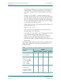
Four models of Alpha 4500A series power meter are available: 4505A,
4510A, 4515A, 4520A. Their capabilities are summarized in Table 1-1
and described below.
Table 1-1 Capabilities of theAlpha 4500A series power-meter models
Model
Function
4505A
4510A
4515A
4520A
Frequency range:
• 1.75–55 MHz
Power range:
• 200 mW to 3 kW
(–7 to +34.8 dBW)
• 1 W to 5 kW
(0 to +37 dBW)
Display method:
• Analog meter
• Digital LED display
• SoftMeter software
Page 1–2
Document Issue 1.0
December 2014
RF Concepts LLC
All power-meter models operate across the frequency range from 1.75 to
55 MHz.
As shown in Table 1-1, the models vary in their power ranges of
operation. No additional “slugs” or accessories are necessary to operate
over the entire power range. This feature is convenient for accurately
measuring an antenna system’s SWR at very low power (such as 1 W) and
then operating at high power (such as 1500 W) without having to make
any changes to the meter.
All models feature enhanced linearity by implementing an algorithm to
compensate for the non-log conformity of the internal logarithmic
amplifier.
The radio-frequency (RF) power estimates reported by the power meters
are temperature- and frequency-compensated for optimum accuracy.
The meters are highly automated and include circuitry to protect against
typical operating anomalies. For example, they automatically determine
the direction of RF power flow, allowing the rear-panel coaxial
connectors to be connected interchangeably between RF source and load
(typically the transmitter and antenna, respectively).
The meters report all measurements as streaming data through the USB
serial port on the back of the unit, enabling real-time data logging of
station performance.
Display method
The power-meter models vary in their display method:
• Models 4505A/4515A display data only via a host PC equipped with
SoftMeter software. They do not have built-in displays.
• Models 4510A/4520A display data via SoftMeter software and, in
addition, via two built-in physical displays:
— Analog meter — Displays either forward power or reflected
power (on the top and middle scales) or SWR (on the bottom
scale).
— Digital LED display — Displays either forward power or
delivered power.
The analog meter exhibits ample damping, which enables rapid
response during normal operation yet minimizes the likelihood of
damage during transit.
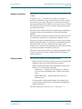
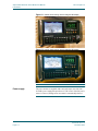
The built-in displays are visible in Figure 1-1 and Figure 1-2.
Document Issue 1.0
December 2014
Page 1–3
11
Ranges of operation
Alpha 4500A Series RF Power Meter User Manual
Introduction
1
Alpha 4500A Series RF Power Meter User Manual
Introduction
RF Concepts LLC
11
Figure 1-1 Model 4510A analog meter and digital LED display
1
Figure 1-2 Model 4520A analog meter and digital LED display
Power supply
Page 1–4
The power meters are supplied with a universal-input (100–240 VAC,
50–60 Hz) power supply that provides a 12-VDC source. If the DC power
source is removed, analog-meter movement is automatically shorted.
Document Issue 1.0
December 2014
RF Concepts LLC
Alpha 4500A Series RF Power Meter User Manual
Introduction
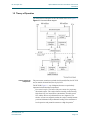
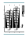
The functional block diagram for all of the models is shown in Figure 1-3.
Figure 1-3 Functional block diagram
11
1.2 Theory of Operation
1
Internal functional
components
The power meter contains two printed circuit boards (PCBs): the RF PCB
and, on models 4510A/4520A, the display PCB.
The RF PCB (Figure 1-3, top of diagram) features two particularly
important internal functional components:
• Directional coupler. The heart of the power meter is a proprietary
directional coupler. The coupler features virtually perfect linearity,
high directivity, low insertion loss (attenuation), favorable return
loss, and the absence of problematic iron-core magnetics. The
absence of iron-core magnetics makes the coupler virtually burnoutproof and eliminates both problematic loading of the transmitter at
low frequencies and potential resonances at high frequencies1.
Document Issue 1.0
December 2014
Page 1–5
Alpha 4500A Series RF Power Meter User Manual
Introduction
RF Concepts LLC
11
• Logarithmic amplifier. A second important and unique feature of the
power meter is the logarithmic amplifier. Made by Analog Devices,
it features an advertised dynamic range of greater than 90 dB. The RF
PCB is designed to use an interior portion of the advertised dynamic
range (~60 dB of the advertised 90 dB) to reduce the effects of nonlog conformity2.
1
The amplifier’s wide dynamic range enables the meter to provide
accurate power and SWR estimates at both low and high power
levels. Therefore, after you set up a transmit station at a low power
level (minimum: for models 4505A/4510A, ~0.25 W of forward
power; for models 4515A/4520A, ~0.5 W of forward power) and
minimize SWR, you can switch to full power without having to adjust
or install different “slugs” in the power meter. This is an advantage
over many other power/SWR meters, which, after switching from
low to high power, often provide conflicting estimates of SWR.
The following paragraphs provide a more complete narrative for
Figure 1-3.
Outputs from the directional coupler relate linearly to the amplitude of
forward- and reverse-traveling voltage waves on the transmission line.
These outputs are multiplexed (by the multiplexer) such that a single
logarithmic amplifier can be used to process signals for forward- and
reverse-traveling waves. Multiplexer channel-to-channel matching is
virtually perfect, and, because of this, some potential measurement errors
simply cancel out3.
Outputs from the multiplexer are routed to the logarithmic amplifier,
which performs as described above.
Outputs from the logarithmic amplifier are in the form of a direct-current
(DC) signal proportional to the root-mean-square (RMS) value of the
input RF signal. An analog-to-digital-converter (A/D) inside the RF
microprocessor converts these signals into digital form.
Outputs from the digital counter and the temperature sensor allow the RF
microprocessor to further refine its estimates of forward- and reversetraveling power by compensating for effects of temperature and
frequency.
1. Shunt inductance of iron-core-magnetics-based couplers can cause undesirable reactive loading of the transmitter due
to insufficient inductance. Increasing the inductance (to alleviate the loading problem) can lead to problematic
resonances at higher frequencies that significantly degrade meter accuracy.
2. For example, this allows the model 4510A to accurately estimate the magnitude of forward power ranging from about
3000 to 0.3 W (40 dB) with a 20-dB margin to measure the lower-amplitude reflected power.The effects of non-log
conformity are further reduced by a compensation algorithm implemented in the RF microprocessor. The
compensation is applied to the upper 44 dB of range (0.2 W to 5 kW for model 4520A).
3. For example, the process of estimating SWR involves the ratio Vr/Vf. In the multiplexed case, some of the potential
error due to the response equalizer and logarithmic amplifier cancel out.
Page 1–6
Document Issue 1.0
December 2014
RF Concepts LLC
Alpha 4500A Series RF Power Meter User Manual
Introduction
The RF microprocessor communicates with the user-interface
microprocessor on the display PCB (models 4510A/4520A only) by way
of an I2C interface. This allows the user-interface microprocessor to send
commands to the RF microprocessor as well as to receive power and SWR
information from the RF microprocessor.
The display PCB enables you to interface with the RF PCB. The display
PCB drives the analog display, digital display, and light-emitting diodes
(LEDs) in the user-interface push buttons. The display PCB also scans the
push buttons to determine which button you have pressed.
Power- conditioning circuitry on the display PCB converts 12 VDC from
the external supply to 5 VDC for the electronics on the two PCBs.
1.3 Product Safety
For safe operation, take the following precautions with the power meter:
• Use only a good-quality 50-ohm coaxial cable to connect the meter to
both the RF source and the antennas, especially if the source’s RF
output level exceeds 200 W. Doing so minimizes cable loss, reduces
the risk of dielectric breakdown, and minimizes radiation and
electrical hazards.
• Use proper grounding throughout your installation.
• If possible, connect the meter to an AC power source that you can
turn on and off. Then, when you are away from your station, you can
turn the power source off and stop the meter’s power cube from
drawing power. Doing so is not only a safety measure but also an
energy-conservation measure, and may extend the service life of the
power cube.
1.4 Product Warranty
The original purchaser of this power meter is covered by a 12-month,
limited factory warranty. For more information about the warranty, go to
rfconcepts.com.
Document Issue 1.0
December 2014
Page 1–7
11
The RF microprocessor drives a USB port on the rear panel of the power
meter. This port allows direct computer access to digital data describing
SWR, forward-power, and reverse-power estimates from the RF
microprocessor. The port is also used in the manufacturing process to
download unit-specific polynomial coefficients to compensate for
temperature, frequency, and non-log conformity of the logarithmic
amplifier.
1
Alpha 4500A Series RF Power Meter User Manual
Introduction
RF Concepts LLC
11
1.5 Product Assistance
Technical assistance from RF Concepts is available from several sources.
• Go to our website at rfconcepts.com and click Support for the
1
following assistance:
— Alpha Forum
— FAQs
— Legacy equipment information
— Manuals
— Repair information
— Software downloads
— Tech tips
— Technical support
• E-mail us by completing a support request at rfconcepts.com.
• Fax us at 303-473-9660.
• Phone us at 303-473-9232.
1.6 Product Specifications
Listed below are the following specifications:
• Operational specifications
• Typical performance specifications
• Serial-interface specifications
Page 1–8
Document Issue 1.0
December 2014
RF Concepts LLC
Alpha 4500A Series RF Power Meter User Manual
Introduction
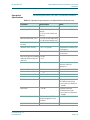
The following table lists the power meter’s operational specifications.
Table 1-2 Operational specifications for the Alpha 4500A series power meter
Parameter
Specification
Notes
Frequency of operation
1.75–55 MHz
Continuous coverage
Power range
0.3 W to 3 kW (4510A and
4505A)
0.5 W to 5 kW (4520A and
4515A)
Minimum detectable power
<0.05 W (4510A and 4505A)
<0.1 W (4520A and 4515A)
Standard deviation of power
accuracy
<2.5%
Absolute power accuracy
<5% (<3% typical)
Compensated for temperature
and frequency
Reference point
RF input port
Either RF connector can be
the input port
Directivity and corresponding >24 dB
indicated SWR for ideal 50- <1.14
ohm load
Reference impedance
50 ohms
Custom models are available
with other reference
impedances
Maximum RF voltage
550 Vrms
Center conductor to shield
Maximum RF current
11 Arms
Operating temperature
–10º to +40º C
Storage temperature
–40º to +50º C
Insertion loss
<0.06 dB
Typically better than
0.015 dB (measured with
type-N connectors installed)
at 14 MHz
Return loss
<–26 dB
Typically better than
–35 dB (measured with
type-N connectors installed)
at 14 MHz
RF connector types
Field-replaceable UHF
(SO239) supplied; N-type
available
Digital data connector
USB
Document Issue 1.0
December 2014
Page 1–9
11
Operational
Specifications
1
Alpha 4500A Series RF Power Meter User Manual
Introduction
RF Concepts LLC
11
Table 1-2 Operational specifications for the Alpha 4500A series power meter
1
Parameter
Specification
DC power requirement
10–14 VDC,
<1 A
Mating DC power connector
with unshielded cable
Digikey PN-839-1015-ND
Input to external AC power
supply
100–240 VAC,
50–60 Hz
Size
8.6"W × 4.7"H × 3.2"D
Weight
9.0 pounds
Typical Performance
Specifications
Notes
Outside sleeve is negative
terminal
External power supply
weights 0.7 pounds
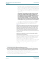
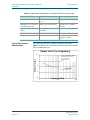
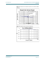
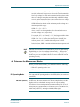
The following graphs show examples of measured performance.
Figure 1-4 Power error as a function of frequency with 0.3 W of forward
power and SWR near unity
! %
%
! Page 1–10
($("*!)!#
!&("!!!!#)"( !''
" !# $!$
#
!
!
! !
Document Issue 1.0
December 2014
RF Concepts LLC
Alpha 4500A Series RF Power Meter User Manual
Introduction
$#
*
1
*'*%,$+$&
$('$*'$&+%*#&)
%#$&#'$'
-$'$
$
(
'
%
#
%
'
(
*
$#
$
$#
$##
$###
$####
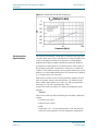
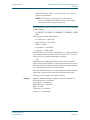
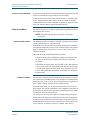
Figure 1-6 Insertion loss as a function of frequency
Document Issue 1.0
December 2014
11
Figure 1-5 Power error as a function of power at 14.1 MHz with SWR
near unity
Page 1–11
Alpha 4500A Series RF Power Meter User Manual
Introduction
RF Concepts LLC
11
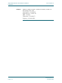
Figure 1-7 Return loss as a function of frequency
1
$#!
" $
!"
#
!
"
Serial-Interface
Specifications
The serial port continuously outputs data at 38,400 bps using 8 data bits,
1 stop bit, and no parity (N,8,1). All characters are human-readable; that
is, they are displayed as ASCII text if directed to a terminal-display
program such as HyperTerminal or RealTerm in Microsoft Windows.
A complete set of data output for one measurement, in either of the two
RF operating modes (PEP or carrier/tune), consists of a so-called data
“sentence.” Each sentence contains a start or sentinel character ($), an end
character (*), and two additional characters (FF). Sentences are separated
by a <carriage return> and <line feed>.
Each sentence consists of seven words, separated by commas. The first
word in a sentence consists of the start character <$> followed by the
letters <APW> and a numerical set, either <01> (RF operating mode =
carrier/tune) or <02> (RF operating mode = PEP).
A typical first word in a sentence is as follows, including the comma
separator:
$APW01,
The next five words represent the following five data fields, separated by
commas:
• Forward power (watts)
• Reflected power (watts)
• SWR
• Temperature (°F) — the internal temperature of the unit and NOT
ambient or room temperature; used for temperature compensation
Page 1–12
Document Issue 1.0
December 2014
RF Concepts LLC
Alpha 4500A Series RF Power Meter User Manual
Introduction
frequency compensation
NOTE: Delivered power is a derived value, not a measured
value. It is calculated as the difference between forward and
reflected power for any given measurement.
A typical string of words following the first word is as follows, including
comma separators:
0.240197,0.031695,2.140988,77.900000,3.482
099
This string represents the following data:
• Forward power = 0.240197 W
• Reflected power = 0.031695 W
• SWR = 2.140988
• Temperature = 77.900000 °F
• Frequency = 3.482099 MHz
The final word of every sentence is indicated by a <*> character followed
by two additional characters that currently are fixed as <FF>. Thus, the
final word in every sentence should appear as follows:
*FF
Immediately after completing the final word in a sentence, the meter
sends a carriage return and line feed. On a Hyperterm screen, the cursor
drops down one line, and the next character is then the sentinel character
<$>, indicating the first word of the next sentence.
The rate at which the sentences are emitted depends on the RF operating
mode. They are more rapid in carrier/tune mode than in PEP mode.
Following are two examples of complete sentences.
Example 1
$APW01,0.240459,0.031606,2.137487,78.012496,3.491939,*FF
RF operating mode = Carrier/tune
Forward power = 0.240459 W
Reflected power = 0.031606 W
SWR = 2.137487
Temperature = 78.012496°F
Frequency = 3.491939 MHz
Document Issue 1.0
December 2014
Page 1–13
11
• Estimated frequency (MHz) — accurate only to +/–2%; used for
1
Alpha 4500A Series RF Power Meter User Manual
Introduction
11
Example 2
RF Concepts LLC
$APW02,0.256680,0.033417,2.129019,78.012496,4.533681,*FF
RF operating mode = PEP
Forward power = 0.256680 W
Reflected power = 0.033417 W
SWR = 2.129019
Temperature = 78.012496 °F
Frequency = 4.533681 MHz
1
Page 1–14
Document Issue 1.0
December 2014
2
2 Power-Meter Components
2.1 (Models 4510A/4520A) Analog Meter and Digital LED Display
2–2
2.2 (Models 4510A/4520A) Control Switches 2–3
2.3 SoftMeter Software 2–4
2.4 Rear-Panel Connectors 2–5
IMPORTANT
!
Do not open the power meter. There are no internal controls or userserviceable parts inside any Alpha 4500A series power meters.
Opening the unit voids the manufacturer’s warranty. Any damage or
problems resulting from opening the unit are not covered by
warranty.
Opening the unit may also result in inaccurate readings and partial or
total electrical failure of the unit.
As discussed in Section 1.1, “Display method,” page 1–3, the four powermeter models vary in their display method:
• Models 4505A/4515A display data only via SoftMeter software.
They do not have built-in displays.
• Models 4510A/4520A display data via SoftMeter software and, in
addition, via a front-panel analog meter and digital LED display.
Numerous control switches control meter operation and display, as
discussed below.
The front panels of models 4510A and 4520A are similar. The front
panel of model 4520A is shown in Figure 2-1.
Document Issue 1.0
December 2014
Page 2–1
Alpha 4500A Series RF Power Meter User Manual
Power-Meter Components
RF Concepts LLC
22
Figure 2-1 Power-meter front panel
2
2.1 (Models 4510A/4520A) Analog Meter and Digital LED Display
Power-meter models 4510A/4520A have two built-in physical displays
that enable you to view meter measurements (see Table 2-1).
Table 2-1 Power-meter models 4510A/4520A physical displays
Display
Purpose
Analog meter
Displays the following:
• On the upper and middle scales, either forward
power or reflected power (depending on the
setting of the Fwd and Ref switches)
• On the bottom scale, SWR
Note: The analog meter does not display delivered
power.
Digital LED display Displays either forward power or delivered power
(depending on the setting of the Del switch).
Note: Del stands for delivered power, defined as
forward power minus reflected power.
Page 2–2
Document Issue 1.0
December 2014
RF Concepts LLC
Alpha 4500A Series RF Power Meter User Manual
Power-Meter Components
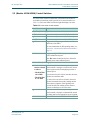
For power-meter models 4510A/4520A, all functions and modes are
accessible from the front panel by means of 16 control switches (see
Table 2-2). Each switch has an indicator light that displays its status.
Table 2-2 Power-meter control switches
Switch
Purpose
Top Row (left to right)
• Fwd
• Ref
• SWR
• PEP
Causes the analog meter to display forward power.
Causes the analog meter to display reflected power.
Causes the analog meter to display SWR.
Toggles the RF operating mode between PEP and
carrier/tune (non-PEP).
For more information on RF operating modes, see
Section 4.4, “Determine the Measurement Modes,”
page 4–3.
• Del
Toggles the digital LED display between forward
power and delivered power.
Note: Del stands for delivered power, defined as
forward power minus reflected power.
Bottom Row (left to right)
• A series of 9
Puts the meter in manual-select power-segmentswitches, labeled selection mode, causing it to lock into one of nine
as follows:
power-segment scales for displaying forward or
reflected power.
– Model 4520A:
10 to 5000
If you do not select one of these switches, the meter
– Model 4510A: operates in AutoSense mode.
0.3 to 3000
Document Issue 1.0
December 2014
If you do select one of these switches, the meter
operates in manual-select mode, locking into the
selected power segment. If the applied power
exceeds the full-scale reading for the selected
segment, no damage occurs to the meter.
• Auto
Puts the meter in AutoSense power-segmentselection mode, causing it to automatically match
the analog meter to the appropriate power segment.
• On/Off
Powers the meter on and off.
Page 2–3
22
2.2 (Models 4510A/4520A) Control Switches
2
Alpha 4500A Series RF Power Meter User Manual
Power-Meter Components
22
NOTE
RF Concepts LLC
The default settings upon initial powerup are the following:
• RF operating mode: PEP
• Power-segment-selection mode: AutoSense
• Analog-meter display: SWR
• Digital LED display: Delivered power
2
2.3 SoftMeter Software
SoftMeter is a PC application that monitors all meter functions
simultaneously. All models of the Alpha 4500A series power meter ship
with SoftMeter software. For models 4505A/4515A, meter readings are
available only via the SoftMeter software.
All of the information that the meter measures is available via the USB
serial port on the back of the unit. The format of the data provided over
the port is described in Section 1.6, “Serial-Interface Specifications,”
page 1–12. Instructions for installing the software are provided in Section
3.2, 3.2, “(Optional) Set Up the Host PC and SoftMeter Software,”
page 3–2.
Currently, no serial commands can be sent to the unit via the serial port.
IMPORTANT
!
Support for configuring and running SoftMeter software is the sole
responsibility of the purchaser. Due to the ever-changing number of PC
hardware and software configurations, we cannot support each user in
configuring his or her PC to correctly run the SoftMeter software.
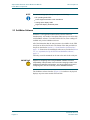
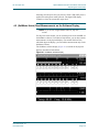
The SoftMeter software interface (Figure 2-2) is similar to the physical
displays on power-meter models 4510A/4520A.
Page 2–4
Document Issue 1.0
December 2014
RF Concepts LLC
Alpha 4500A Series RF Power Meter User Manual
Power-Meter Components
22
Figure 2-2 Alpha 4500A SoftMeter screen
2
2.4 Rear-Panel Connectors
The rear panel of each power-meter model contains the following (none
of them user-adjustable):
• Power-supply input connector (12 VDC) and USB connector for
serial-data output (upper left)
• USB connector for serial-data output (upper left)
• Input and output RF coax connectors (along the bottom)
• Label showing the model and serial number and other relevant
information (center)
Document Issue 1.0
December 2014
Page 2–5
Alpha 4500A Series RF Power Meter User Manual
Power-Meter Components
RF Concepts LLC
22
2
Page 2–6
Document Issue 1.0
December 2014
3
3 Setting Up the Power Meter
3.1
3.2
3.3
3.4
3.5
Position the Meter 3–1
(Optional) Set Up the Host PC and SoftMeter Software 3–2
Connect the Cables 3–3
(SoftMeter Users) Configure the PC’s USB COM Port 3–5
(Optional) Change the RF Coaxial Connectors 3–5
3.1 Position the Meter
Procedure 3-1 Position the meter
Step 1
Unpack the meter and place it so as to ensure the following:
• The surface is level.
• An appropriate AC power source is accessible.
HINT: If you anticipate being away from your station for any
period of time, we suggest that you use an AC power source
that can be turned on and off. Even when the meter is turned
off, if the power source is on, the meter’s power supply
draws power and provides 12 V to the meter. Using a
separately controllable power source can thus conserve
energy and enhance safety, and may extend the service life
of the meter’s power supply.
• The front of the meter is viewable and the control switches are
accessible.
NOTE: There are no user-adjustable controls on the rear panel.
After the cables are connected, you will not need to access
the back panel.
Step 2
(Models 4510A/4520A) Zero the analog meter:
2a Determine where the analog meter needle rests with respect to the
zero value on the upper scale.
Document Issue 1.0
December 2014
Page 3–1
Alpha 4500A Series RF Power Meter User Manual
Setting Up the Power Meter
33
3
RF Concepts LLC
2b If necessary, zero the needle by carefully inserting a small jeweler’s
flathead screwdriver into the adjustment hole directly under the meter
face and adjusting the needle.
3.2 (Optional) Set Up the Host PC and SoftMeter Software
NOTE: If you are not using SoftMeter software, skip this
section.
All models of the Alpha 4500A series power meter ship with SoftMeter
software. For models 4505A/4515A, meter readings are available only via
the SoftMeter software.
IMPORTANT
!
Support for configuring and running SoftMeter software is the sole
responsibility of the purchaser. Due to the ever-changing number of PC
hardware and software configurations, we cannot support each user in
configuring his or her PC to correctly run the SoftMeter software.
Procedure 3-2 Set up the host PC and SoftMeter software
Step 1
Set up a host PC with the following:
• Operating system: a relatively current Microsoft operating system
• Capacity: 10 MB free hard-disk space, 256 MB RAM
• Port: an available USB serial port
Step 2
Install the SoftMeter software.
NOTE:
• For models 4510A/4520A, this step is optional.
• For models 4505A/4515A, this step is required.
2a On the host PC, navigate to the directory in which you want the
SoftMeter software to run.
2b Unzip the SoftMeter software.
2c Open the README file and follow the instructions therein.
Page 3–2
Document Issue 1.0
December 2014
RF Concepts LLC
Alpha 4500A Series RF Power Meter User Manual
Setting Up the Power Meter
33
3.3 Connect the Cables
Procedure 3-3 Connect the cables
Step 1
Ensure that your installation is properly grounded.
Step 2
If you are using SoftMeter software, connect the meter to the host PC.
Use a USB cable to connect the PC’s USB port to the meter’s USB port.
The connector sends engineering information calculated by the meter —
including power output levels, reflected power level, and SWR — as a
serial data stream in USB format to the host PC. For the format of the data
stream, see Section 1.6, “Serial-Interface Specifications,” page 1–12.
Step 3
Connect the meter to the power supply.
3a Plug the power supply into the meter:
1. Locate, on the power supply, a two-wire cable with a small barrel
connector on the end.
2. Locate, on the back of the meter, a recessed male barrelconnector receptacle labeled 12 VDC.
3. Plug the cable into the receptacle.
The power supply operates from a 100–240-V 50–60-Hz AC power
source.
IMPORTANT
!
The power supply provides DC output. Therefore, the power supply’s
power cable and barrel connector as well as the meter’s recessed male
connector are polarized.
Although the meter is protected against reverse-polarity connection, do
not tamper with or change the power-supply cable or the barrel
connector. Any such tampering or change can lead to damage or failure
of the meter. Such damage or failure is not covered under warranty.
3b Plug the power supply into an AC power source.
3c (Models 4510A/4520A) Power up the meter by momentarily pressing
the ON/OFF button.
The following sequence occurs on these models:
1. The switch lights, confirming that the meter is powered on.
2. A self-test sequence briefly lights each of the switches.
3. If no RF power is present, the digital LED display shows a
number in the range 0000–0003.
4. The analog meter lights up.
5. The meter makes a short audible tone.
Document Issue 1.0
December 2014
Page 3–3
3
Alpha 4500A Series RF Power Meter User Manual
Setting Up the Power Meter
RF Concepts LLC
33
NOTE: For models 4510A/4520A, the default settings upon
initial powerup are as follows:
• RF operating mode: PEP
• Power-segment-selection mode: AutoSense
• Analog-meter display: SWR
• Digital LED display: Delivered power
3
Step 4
Connect the meter to the RF source (transmitter) and load (antennas) to be
measured.
NOTE: The meter is normally supplied with ultra-highfrequency (UHF) style (or SO-239) coaxial connectors —
for example, they mate with PL-259 plugs — or optionally
with N-type connectors. However, the connectors are fieldreplaceable if you prefer a different style of connector (BNC
or type N) or if the connectors become damaged. For more
information, contact the factory. There is no requirement that
both connectors be of the same type.
If you replace a coaxial cable, use only good-quality 50-ohm
cable to connect the meter to both the RF source and the load.
4a Locate, on the back of the meter, the two RF connectors.
4b To the two connectors, securely attach the following:
• Load (output): the 50-ohm coaxial cable from the antenna (or
from a separate antenna switch if one is used to select from
among various antennas)
• Source (input): the 50-ohm coaxial cable from the output stage of
the HF amplifier or transceiver
NOTE: The meter automatically senses the direction of RF flow
through the meter, so you can attach the load and source
interchangeably to either of the two connectors. However,
factory calibration is performed with the load attached to the
RF connector nearer the USB connector, and therefore better
accuracy is expected with this configuration.
In connecting the load and source, it is good practice to do the
following:
• Use only high-quality coaxial cable for all RF connections.
• Keep the cable length as short as practical to reduce line loss.
• Whenever you mate the coaxial plugs to the meter’s coaxial
connectors, carefully inspect, tighten, and, as needed, clean the
plugs to ensure long life for the connectors.
Page 3–4
Document Issue 1.0
December 2014
RF Concepts LLC
Alpha 4500A Series RF Power Meter User Manual
Setting Up the Power Meter
3.4 (SoftMeter Users) Configure the PC’s USB COM Port
NOTE: If you are not using SoftMeter software, skip this
section.
Procedure 3-4 Configure the USB COM port
Step 1
On the host PC, click Start.
Step 2
Search for and open Device Manager, then open Ports (COM & LPT).
Procedures for doing so can vary according to operating system. A typical
sequence is to right-click Computer, then select Properties > Hardware
> Device Manager > Ports (COM & LPT).
Step 3
Right-click the COM port number that the system has assigned to the
meter and left-click Properties.
Step 4
Click the Port Settings tab and set the following values:
• Bits per second: 38400
• Data bits: 8
• Parity: None
• Stop bits: 1
• Flow control: None
Step 5
Click Advanced and set the COM port number to the port that you wish
to use (COM1 to COM8).
Step 6
Click OK to close all windows, then exit Device Manager.
3.5 (Optional) Change the RF Coaxial Connectors
The RF coaxial connectors are field replaceable. If the connectors become
damaged or if different-style connectors are to be installed, you can
replace them easily in the field.
Document Issue 1.0
December 2014
Page 3–5
33
For standard SO-239 UHF-style connectors, inspect the male PL259 connectors on the end of the coaxial cable before mating
them with the connectors on the back of the meter. Use a finegrade file to remove any excess solder and remnants of solder
flux on the center pin.
3
Alpha 4500A Series RF Power Meter User Manual
Setting Up the Power Meter
33
IMPORTANT
!
3
RF Concepts LLC
Do not open the power meter. There are no internal controls or userserviceable parts inside any Alpha 4500A series power meters.
Opening the meter voids the manufacturer’s warranty. Any damage
or problems resulting from opening the meter are not covered by
warranty.
Opening the meter may also result in inaccurate readings, reduced
accuracy, and partial or total electrical failure of the unit.
Procedure 3-5 (Optional) Change the RF coaxial connectors
Step 1
Disconnect all electrical cables from the meter.
Step 2
Turn the meter face-down on a soft surface, tilting it so that it rests on the
carrying handles.
Step 3
With a #2 Phillips screwdriver, unscrew and remove the four stainlesssteel machine screws and lock washers for each connector to be removed.
Set the screws and washers aside. If one is lost, replace it with an identical
stainless-steel screw and lock washer.
Page 3–6
Step 4
Remove the connector by drawing it straight up away from the meter,
using slight force if necessary to remove it from its socket connection on
the meter’s printed circuit board (PCB).
Step 5
Using a flashlight, inspect the mating contact for the connector center pin
and the chassis area around the connector. If necessary, clean these
surfaces using a Q-tip and alcohol.
Step 6
Install the new connector by pressing it gently into the socket connection
on the meter’s PCB. The connector should fit snugly into the PCB.
Step 7
Align the screw mounting holes of the new connector with the holes in the
back of the meter.
Step 8
Secure the new connector using the factory-supplied screws (stainlesssteel machine-type 8-32 x 5/16"). Ensure that the screws are tight before
applying RF power.
Document Issue 1.0
December 2014
4
4 Operating the Power Meter
4.1 Power the Meter Up/Down 4–1
4.2 Connect the Meter to the RF Source and Load to Be Measured
4–2
4.3 Determine What to Measure 4–2
4.4 Determine the Measurement Modes 4–3
4.5 (SoftMeter Users) Read Measurements on the Software Display
4–5
4.6 (Models 4510A/4520A) Read Measurements on the Physical
Displays 4–7
4.7 (Models 4510A/4520A) Enter/Exit Sleep Mode 4–8
IMPORTANT
!
• The Alpha 4500A series power meter is designed to be easy to set
up, operate, and maintain. However, failure to carry out each
procedure exactly as described in this manual is likely to lead to
meter damage. Such damage is not covered under warranty.
Damage to other station equipment may also result.
• If the meter faults during operation, resolve the fault as described in
Chapter 5, “Troubleshooting the Power Meter.”
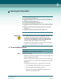
4.1 Power the Meter Up/Down
Procedure 4-1 Power the meter up or down
Step 1
To power the meter up:
• (Models 4515A/4505A) Connect the meter to the power supply and
the power supply to an AC outlet.
• (Models 4510A/4520A) Connect the meter to the power supply and
the power supply to an AC outlet. Then momentarily press the ON/
OFF button.
The following startup sequence occurs (models 4510A/4520A):
1. The switch lights, confirming that the meter is powered on.
2. A self-test sequence briefly lights each switch.
3. If no RF power is present, the digital LED display shows a
number in the range 0000–0003.
Document Issue 1.0
December 2014
Page 4–1
Alpha 4500A Series RF Power Meter User Manual
Operating the Power Meter
RF Concepts LLC
44
4. The analog display lights up.
5. The meter makes a short audible tone.
NOTE: For models 4510A/4520A, the default settings upon
initial powerup are the following:
4
• RF operating mode: PEP
• Power-segment-selection mode: AutoSense
• Analog-meter display: SWR
• Digital LED display: Delivered power
Step 2
To power the meter down:
• (Models 4510A/4520A) Momentarily press the ON/OFF button.
• (Models 4505A/4515A) Disconnect the meter from the power supply
or the power supply from the AC outlet.
4.2 Connect the Meter to the RF Source and Load to Be Measured
Ensure that the meter is connected to the RF source and load to be
measured as described in Section 3.3, “Connect the Cables,” Step 4,
page 3–4.
4.3 Determine What to Measure
You can measure the following with the power meter:
NOTE: The following text is taken from Section 1.1, “Product
Capabilities,” page 1–1.
• Forward power — This is the power traveling in the forward
direction, from the transmitter to the load (typically the coaxial
transmission line leading to the antenna). For the ideal case of unity
SWR (SWR = 1), this is also the power delivered by the transmitter
to the load.
• Reflected power — This is the power traveling in the reverse
direction, from the load to the transmitter. For the ideal case of unity
SWR, the reflected power is zero.
• Delivered power — This is the forward power minus the reflected
power — in other words, the power delivered by the transmitter to the
load regardless of SWR value. For example, if the forward power is
100 W and SWR = 4, then the reflected power is 36 W and the
delivered power (power delivered by the transmitter to the load) is
64 W.
Page 4–2
Document Issue 1.0
December 2014
RF Concepts LLC
Alpha 4500A Series RF Power Meter User Manual
Operating the Power Meter
traveling (reflected) voltage waves exist on the coaxial transmission
line. Large voltages can exist on the transmission line at places where
these two voltages are in phase and coherently add. Small voltages
can exist on the transmission line at places where these two voltages
are out of phase and coherently subtract.
SWR is defined as the ratio of the maximum possible voltage to the
minimum possible voltage:
SWR = (Vf + Vr) / (Vf – Vr)
where Vf and Vr are the magnitudes of the forward- and reversetraveling voltage waves, respectively.
For example, if Vf = 100 V and Vr = 50 V, the largest possible voltage
is 150 V and the smallest possible voltage is 50 V. So
SWR = 150 / 50 = 3. Further, the forward power is 200 W, the
reflected power is 50 W, and the delivered power is 150 W.
In the ideal case, SWR = 1 and the coaxial transmission operates with
minimum loss.
HINT
(Models 4510A/4520A) We recommend that you use the dual analog/
digital display to view two readings simultaneously — SWR on the
analog meter and forward or delivered power on the digital LED display.
In this way, you can verify that both the RF source and the RF load are
operating correctly.
4.4 Determine the Measurement Modes
Before you make measurements, you should determine the following:
• Which RF operating mode to use
• Which power-level mode to use
RF Operating Mode
PEP Mode (Default)
You can set the RF operating mode to either PEP (default) or carrier/tune
(non-PEP).
In PEP mode, the meter measures 497 discrete samples, then uses the 6
highest values to calculate the average value for a given reading.
Use this mode for normal operation after station tuneup. Use it, too, for
most peak-power measurements of continuous-wave (CW) Morse code,
radio teletype (RTTY), and single-sideband (SSB) signals.
Document Issue 1.0
December 2014
Page 4–3
44
• Standing-wave ratio (SWR) — Forward-traveling and reverse-
4
Alpha 4500A Series RF Power Meter User Manual
Operating the Power Meter
44
Carrier/Tune (Non-PEP) Mode
RF Concepts LLC
In carrier/tune mode, the meter measures 32 discrete samples and uses all
of them to calculate the average value for a given reading.
Use this mode for laboratory-quality measurements in a constant-signal
or key-down operating scenario when you set up a station or antenna;
evaluate SWR; tune an exciter, amplifier, or antenna; or match an output
stage to an antenna using an antenna-matching network.
4
Power-Level Mode
You can set the power-level mode to either AutoSense (default) or any of
nine manual-select choices.
NOTE: This mode selection affects operation of the analog
meter only.
AutoSense Mode (Default)
The Auto switch on the front panel to the right of the nine power-segment
switches puts the meter in AutoSense mode.
In this mode, the meter automatically switches among power segments to
best match the measured power level. The switch for each power segment
lights or darkens as the meter detects or ceases to detect power levels
within that segment.
This mode has both practical and reliability benefits:
• It keeps the analog meter’s deflection roughly in the center third of
the scale, for more accurate readings and reduced overall needle
movement.
• It has a built-in response delay. If power falls to lower than full-scale
value of a lower scale, the meter pauses at the current scale for about
2 seconds, then drops to the lower scale. Thus, if power level varies,
such as during SSB radio communication, the meter does not bounce
between scales.
Manual-Select Mode
The nine power-segment switches put the meter in manual-select mode.
You can also press the Auto switch, if it is already lit, to accomplish the
same thing; after you do so, if you do not then select a power segment, the
meter returns to the last segment used in AutoSense mode.
In manual-select mode, you can lock the analog meter into one of nine
power ranges. This is most useful when you are confident of the expected
power level to be measured and want the needle deflection to stay within
a certain part of the measurement scale.
You can move from one power segment to another just by pressing the
switch for the new segment; you need not press the switches sequentially.
If you overshoot or undershoot and select a power range that is larger or
smaller than the RF presence on the coaxial line, the meter simply reads
zero or full scale; no damage is done. For example, if the meter is
Page 4–4
Document Issue 1.0
December 2014
RF Concepts LLC
Alpha 4500A Series RF Power Meter User Manual
Operating the Power Meter
4
4.5 (SoftMeter Users) Read Measurements on the Software Display
NOTE: If you are not using SoftMeter software, skip this
section.
For all power-meter models, you can read the power levels and SWR via
the SoftMeter software. For models 4510A/4520A, you can also read the
measurements via the physical displays. For models 4505A/4515A,
which lack physical displays, you can read the measurements only via the
SoftMeter software.
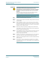
The SoftMeter software display (Figure 4-1) is similar to the physical
displays on models 4510A/4520A.
Figure 4-1 SoftMeter software display
Document Issue 1.0
December 2014
44
measuring forward power and you select 0.3 W but 3 KW of RF power is
applied, the analog meter reads full scale. The digital LED display
continues to show the accurate RF output level.
Page 4–5
Alpha 4500A Series RF Power Meter User Manual
Operating the Power Meter
RF Concepts LLC
44
Procedure 4-2 Read measurements on the software display
Step 1
4
Select the RF operating mode by clicking PEP to toggle between the
following:
• PEP (switch is on)
• Carrier/tune (switch is off)
Step 2
Select the power-level mode by clicking either of the following:
• Auto for AutoSense mode
• A specific power-segment switch:
— For model 4520A, 10 W to 5 kW
— For model 4510A, 0.3 W to 3 kW
Step 3
Read the power levels or SWR as follows (see Table 4-1).
Table 4-1 Reading measurements on the physical displays
Page 4–6
For this
measurement...
Click...
And read the measurement
here...
Forward power
Del until NOT lit Top row of the screen display
Delivered power
Del until lit
Reflected power
—
Middle row of the screen
display
SWR
—
Bottom row of the screen
display
Document Issue 1.0
December 2014
RF Concepts LLC
Alpha 4500A Series RF Power Meter User Manual
Operating the Power Meter
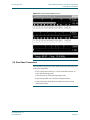
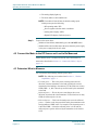
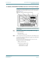
For power-meter models 4510A/4520A, you can read the power levels
and SWR not only via the SoftMeter software but also via the physical
displays (Figure 4-2).
Figure 4-2 Models 4510A/4520A: physical displays
Procedure 4-3 (Models 4510A/4520A) Read measurements on the
physical displays
Step 1
Select the RF operating mode by pressing the PEP switch to toggle
between the following:
• PEP (switch is lit)
• Carrier/tune (switch is not lit)
Step 2
Select a measurement mode for the analog meter (either SWR or Power)
by momentarily pushing the SWR button to toggle between SWR (LED
lit) and Power (LED dark).
If you select Power mode (LED dark), then select a power level by
pressing the switch for one of the following:
• Auto for AutoSense mode
• A specific power-segment switch:
— Model 4510A: 0.3 to 3000
— Model 4520A: 10 to 5000
Document Issue 1.0
December 2014
Page 4–7
44
4.6 (Models 4510A/4520A) Read Measurements on the Physical Displays
4
Alpha 4500A Series RF Power Meter User Manual
Operating the Power Meter
44
Step 3
RF Concepts LLC
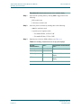
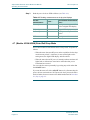
Read the power levels or SWR as follows (see Table 4-2).
Table 4-2 Reading measurements on the physical displays
4
For this
measurement...
Press...
And read the measurement
here...
Forward power
Fwd
Analog meter’s top or middle
scales or digital LED display
Delivered power
Del
Digital LED display
Reflected power
Ref
Analog meter’s top or middle
scales
SWR
—
Analog meter’s bottom scale
4.7 (Models 4510A/4520A) Enter/Exit Sleep Mode
Power-meter models 4510A/4520A feature a sleep mode. It operates as
follows:
• When the meter detects no RF power on the coaxial line for the sleepmode timeout period (3–6 minutes), it turns off the lights on the
analog meter, the digital LED display, and all switches.
• When the meter detects RF power, it instantly awakens and turns all
lights back on without user intervention. All modes that you set
beforehand are restored.
You can wake the meter up manually by pressing any switch other than
the ON/OFF button.
If you turn the meter off via the ON/OFF button or by disconnecting the
power, the last-used modes are NOT preserved when you turn the meter
back on. Rather, the meter returns to the default modes listed in Procedure
4-1, Step 2, page 4–2.
Page 4–8
Document Issue 1.0
December 2014
5
5 Troubleshooting the Power Meter
Meter does not power up
CHECK: Check the DC power supply and connector polarity.
• If the power supply does not measure 12 VDC, replace it.
• If the connector polarity (the connector on the rear of the
meter is a 5.5 x 2.5 mm coaxial power jack) is not tip positive
(+) and barrel negative (–), replace the power supply.
SWR values are consistently
high
CHECK: Check the coax connectors and contact centers
between the meter and the antenna/load for continuity,
connection tightness, and integrity (lack of corrosion or
damage).
• If the connectors are of questionable integrity, try replacing
all of them.
• If the connectors are damaged, replace them.
CHECK: Check the antenna switch for correct operation and
correct antenna selection.
• Make adjustments as needed.
SoftMeter display at high
power is erratic
CHECK: Check the USB cable for shielding.
• If it is not properly shielded, shield it. At higher RF power
levels, RF power commonly couples into the USB cable that
connects the meter to the computer. This coupled power can
generate electrical noise that degrades the data stream to the
computer and causes irrelevant or erroneous data to be
displayed on the computer screen.
CHECK: Check the station and PC grounding.
• If both are not properly grounded, ground them.
Document Issue 1.0
December 2014
Page 5–1
Alpha 4500A Series RF Power Meter User Manual
Troubleshooting the Power Meter
RF Concepts LLC
55
5
Page 5–2
Document Issue 1.0
December 2014
Terminology
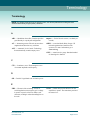
Terminology
NOTE: For detailed explanations of the following terms, see various publications including the latest
American Radio Relay League (ARRL) Handbook.
A
AB1 — Modulation class AB1. Class that provides
good linearity in a push-pull configuration.
AC — Alternating current. Electric current whose
magnitude and direction vary with time.
ALC — Automatic Level Control. Technology
that automatically controls output power.
ampere — Unit of electric current (1 coulomb per
second).
ARRL — American Radio Relay League. US
national organization of amateur radio
operators. For more information, go to
www.arrl.org.
AWG — American wire gauge. Standard method
of denoting wire diameter.
C
CW — Continuous wave. Electromagnetic wave
of constant amplitude and frequency.
D
dB — Decibel. Logarithmic unit of relative power.
E
EBS — Electronic bias switching. A form of
switching that increases negative grid 1 voltage
in pauses in speech or between Morse code
elements, resulting in reduced standing bias on
the tube.
Document Issue 1.0
December 2014
exciter — Radio that provides RF drive for the
amplifier to operate. The transmitter portion of
the transceiver.
Page Term–1
Alpha 4500A Series RF Power Meter User Manual
Terminology
RF Concepts LLC
F
FCC — Federal Communications Commission.
For more information, go to www.fcc.gov.
FM — Frequency modulation. Modulation scheme
in which information is conveyed over a carrier
wave by variations in frequency.
FSK — Frequency-shift keying. Type of
frequency modulation in which information is
conveyed by shifts in the output frequency
between predetermined values.
H
HF — High frequency. Radio frequency within the
range 3–30 MHz.
HV — High voltage. Electrical circuit in which the
voltage used presents risk of both electric shock
and electrical arcing.
Hz — Hertz. One periodic event per second.
I
Ip — Idling plate current. Plate current measured
when the amplifier is keyed and RF is not
present.
K
key — Signal from the radio to the amplifier that
instructs the amplifier to switch from
RECEIVE to TRANSMIT mode because the
radio is ready to generate RF power.
kV — Kilovolt. 1000 V.
kVA — Kilovolt–ampere.
kW — Kilowatt. 1000 W.
L
LED — Light-emitting diode. Semiconductor
diode that emits incoherent narrow-spectrum
light, providing a form of electroluminescence.
LV — Low voltage. Electrical circuit in which the
voltage used presents risk of electric shock but
only minor risk of electrical arcing.
M
mA — Milliampere. 10–3 ampere.
Page Term–2
MHz — Megahertz. 106 Hz.
Document Issue 1.0
December 2014
RF Concepts LLC
Alpha 4500A Series RF Power Meter User Manual
Terminology
O
OPR — Operate.
P
PCB — Printed circuit board. Board that
mechanically supports and electrically connects
electronic components.
PEP — Peak envelope power. Average power
supplied to the antenna transmission line by a
transmitter during one RF cycle at the crest of
the modulation envelope under normal
operating conditions.
PSK — Phase-shift keying. Digital modulation
scheme in which information is conveyed by
changes, or modulations, in the phase of a
reference signal.
Q
QSK — Quick-shift keying. Digital modulation
scheme in which the transmitter is on only for
the duration of each dot or dash and switches to
RECEIVE mode between each dot or dash,
allowing the user to hear any signal being sent.
R
RCA — Radio Corporation of America. Also a
type of interconnecting plug.
RF — Radio frequency. Frequency within the
range 3 Hz to 300 GHz.
RG-x/x — Coaxial cable type.
RMS — Root mean square. Statistical measure of
the magnitude of a varying quantity such as a
wave.
RTTY — Radio teletype. Telecommunications
system consisting of two or more teleprinters
using radio as the transmission medium.
S
SSB — Single sideband. Modulation scheme that
refines upon amplitude modulation.
SSTV — Slow-scan television. Picturetransmission method for transmitting and
receiving static pictures via radio.
Document Issue 1.0
December 2014
STBY — Standby. Mode in which an electronic
appliance is turned off but under power and
ready to activate on command.
SWR — Standing-wave ratio. Ratio of the
maximum possible voltage (or current) to the
minimum possible voltage (or current) on a
transmission line.
Page Term–3
Alpha 4500A Series RF Power Meter User Manual
Terminology
RF Concepts LLC
T
T/R — Transmit /receive.
transceiver — Device that has both a transmitter
and a receiver within the same circuitry or
chassis.
U
UHF — Ultra-high frequency. Radio frequency
US — United States.
within the range 300–3000 MHz (3 GHz).
V
VAC — Volts of alternating current.
VDC — Volts of direct current.
VHF — Very high frequency (30 to 300 MHz).
Page Term–4
VSWR — Voltage standing-wave ratio. Example:
If VSWR = 1.2:1, the maximum possible
voltage on the transmission line is 1.2 times the
minimum possible voltage on the transmission
line.
Document Issue 1.0
December 2014
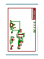
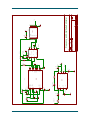
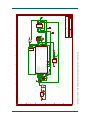
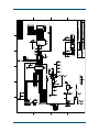
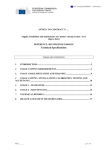
Schematics
Schematics
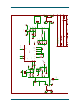
NOTE: The following pages contain detailed schematics for the Alpha 4500A series power meter.
io 0
io 0
GND
3
2
3
2
1
J1
5
4
1
io 0
io 0
GND
5
io 0
4
GND
cal
3
2
1
J3
io 0
io 0
io 0
C500
VSAMP
pas 1
pas 1
pas 1
1050
1050
R5
R42
GND
pas 1
R39
io 0
sup 0
pas 1
pas 1
L1
pas 1
R24
sup 0 pas 1
paspas
1 1
pas 1
R13
R14
pas 1
pas 1
pas 1
L3
C1
pas 1
GND
pas 1
pas 1
pas 1
R1W
sup 0
1
GND
pas 1
8
14
V5-
pas 1in 0
in 0
pas 0
V5+
R40
C2
0.1uF
pas 1
0.1uF
pas 1
pas 1
sup 0
pas 1
R23
100pF COG
pas 1
R34
75
R7
200
C3
pas 1
paspas
1 1
pas
pas
11
io 0
sup 0 pas 1
1050
R6
pas 1
J8
1
2
3
io 0
-VS
+VS
IN0
pas 0
12
A1
pas 0
A0
13
IN1
3
pas 1 pas 0
R500
pas 1
A0
AD8184
U1
75
IN2
5
pas 1 pas 0
75
R501
pas 1
11
pas 0
ENABLE*
pas 0
6
GND
pas 0
GND
NC
IN3
MXOUT
R19
R20
R21
R22
pas 1
pas 1
pas 1 pas 1
pas 1
pas 1
GND
Coupler
pas 1
pas
sup
1 0
pas 1
pas 1
pas 1
pas 0
9
R41
pas 0
7
sup 0
GND
R1
J9
pas 1
pas 1
L4
200
R2
paspas
1 1
pas 1
pas 1 pas 1
C4
L2
R43
1050
1050
R3
R38
75 pas 1
1050
100pF COG
R4
pas 1
pas 1 pas 1
pas 1
io 0
10
OUT
GND_3
4
pas 0
sup 0
GND_2
2
pas 0
io 0
A1
GND
sup 0
1
2
3
1
2
3
io 0
GND
pas 1
pas 1
pas 1
pas 1
pas 1
GND
sup 0
1
2
3
GND
GND
sup 0
sup 0
sup 0
sup 0
1
2
3
io 0
io 0
GND
4
io 0
5
GND
io 0
io 0
io 0
J4
sup 0
sup 0
3
2
1
P$2io 0
2 1
P$1
io 0
1
4
5
J2
1
1
2 cal
3
2
3
io 0
io 0
GND
2
3
GND
sup 0
sup 0
CASE6
io 0
io 0
CASE5
J5
CASE6
sup 0
C35 +
4.7uF 16V
J6
VCC1
io 0
io 0
1
io 0
3
2
TP12V
DP3
DM2
GND
P$1
P$2
GND
10nF
C36
pas 1
pas 1
100pF
C31
22.1
R32
0.1uF
pas 1
U15
GND
GND
U17
C32
pas 0
V5+
U13
pas 0
pas 1
pas 1
TP7
DNS
4.75k
R502
R503
GND
7805
pas 1
pas 1
pas 1
1uF
C33
19
pwr 0
io 0
io 0
pasout
1 0
25
15
16
17
27
out 0 28
in 0
in 0
20
pwr 0 4
pwr 0
GND
+
pas 1
0.1uF
C34
10nF
FT232RL
GND
USBDP
USBDM
3V3OUT
OSCI
OSCO
RESET
VCC
VCCIO
U16
V12+
sup 0
GND
GND
GND
TEST
CBUS0
CBUS1
CBUS2
CBUS3
CBUS4
TXD
RXD
RTS
CTS
DTR
DSR
DCD
RI
pas 1
pas 1
GND
7 pwr 0
18 pwr 0
21 pwr 0
26 in 0
23 io 0
22 io 0
13 io 0
14 io 0
12 io 0
1 out 0
5 in 0
3 out 0
11 in 0
2 out 0
9 in 0
10 in 0
6 in 0
TP
TP
1k
R37
GND
io 0
UPTX
pas 1
UPRX
TP1
TP2
0
M5
J10
io 0
M1
GND
0
Calibrate
0
GND
0
C26 pas 1
io 0
+
+
M2
GND
0
TP
0
5V-
V5-
pas 1
R31
39
pas 1
+
pas 1
10uF C25
pas 1
C27 pas 1
sup 0
P3
P2
io 0
io 0
P1
io 0
12/23/2014 2:14:45 PM f=0.68 C:\Prilab1\4516\4516-211\EAGLE\archive\4516-211.sch (Sheet: 2/5)
GND
io 0
3
CASE5
io 0
io 0
0
0
NC3
sup 0
io 0
4
GND-4
2
pas 1
pas 1
pas 1
suppas
0 1
GND2
sup 0
D1
pas 1
GND
PWR1
pas 1
pas 1
P$4io 0
P$2
P$2io 0
P$1
P$2io 0
P$4
P$3io 0
P$3
COM
sup 0
io 0
sup 0
OUT
io 0
OUT
GRD
io
0
GRD
IN io 0
IN
+12io 0
B
1
io 0
pas 1
pas 1
sup 0
0.1uF
pas 1
pas 1
F1
C501
C37
0
0
io 0
P$1
sup 0
0
0
io 0
io 0
5
5
io 0
4
4
io 0
3
3
io 0
2
2
io 0
1
1
io 0
0
0
io 0
sup 0
10uF
pas 1
10uF
pas 1
sup 0
io 0
V5+
0
pas 1
pas 1
GND
0
pas 1
pas 1
io 0
pas 1
pas 1
C-
GRND
OUT
C+
S_NOT
M3
1983-5
U12
PWR
sup 0
1
io 0
0.33uF
C30
0.33uF
C29
0.33uF
C28
P4 io 0
P5 io 0
P6 io 0
0
M4
GND
sup 0
io 0
0
GND
sup 0
0
0
V5+
Power and Comms
pas 1
301
R16
MXOUT
560pf
C5
pas 1
pas 1 pas 1
GND
VSAMP
100
pas 1
suppas
0 1
R9
C19
pas 1
pas 0
pas 0
pwr 0
pwr 0
8
7
pas 0
in 0
GND
2
15
10nF
4
5
8
9
GND
0.1uF
pas 0
5
V5+pas 0 6
C20
pas 1
U2
pas 0
pas 0
8309E
pas 1
pas 1
C13
GND 10nF
C7
22.1
pas 1
pas 1
10nF
INT
ENB
VPS
INP
C17
pas 1
pas 1
560pF COG
VPS1
VPS2
U6
8307
pas 1
R15
20
pas 1
OUT
OFS
COM
INM
LMHI
LMLO
INHI
INLO
1nF
C21
pas 0
pas 0
pas 0
pas 0 pas 1
GND
4
3
2
1
COM1
COM2
PADL_2
PADL_3
PADL_4
PADL
VLOG
FLTR
ENBL
LMDR
8309
U2
pas 0
pas 0
pas 0
pas 0
pas 0
RFDC
GND
pas 1
pas 0 sup 0
pas 0
pas 0
pas 0
pas 0
GND
7
1
3
6
11
14
13
12
16
10
pas 1
R10
pas 1
sup 0 pas 1
pas 1
pas 1
pas 1
C8
sup 0
0.1uF
sup 0
GND
pas 1
pas 1
sup 0 pas 1
sup 0
C18
R8
sup 0
R12
P1
P2
P3
P4
io 0
io 0
io 0
3016
sup 0
GND
Q
QN
GND
VCC-ENBL_NOT
IN-
IN+
VCC+
C11
pas 1
U3
C12
10uF
V5+
pas 1
pas 1
10nF
+
io 0
pas 1
pas 1
22.1
50
pas 1
pas 1
R11
pas 1
pas 1
50
0.1uF
P16
io P15
0
io P14
0
io P13
0
io P12
0
io 0P11
io P10
0
io 0 P9
io 0
10nF
C9
+PWR
Q10
Q9
Q7
Q8
MR
CP
Q0
U4
Q11
Q5
Q4
4040
Q6
Q3
Q2
Q1
-PWR
pas 1 sup 0
GND
GND
P1 io 0
P2 io 0
P3 io 0
P4 io 0
P5 io 0
P6 io 0
P7 io 0
P8 io 0
GND
F/8
Frequency and Amplitude Estimator
3016D
P5 io 0
P6 io 0sup 0
P7 io 0
P8 io 0
pas 1
sup 0
C16
io 0
P4
4IN
1790-3
OUT6
GD2
GND
P6 io 0pas 1
1uF
+ C23
1k
R18
+
pas 1
C24
1uF
0
10pF
io 0
0
1
2
io 0
2
1
Y1
GND
io 0
F/8
3016D
10pF
C22
TP7
8309E
RFDC
io 0
io 0
io 0
io 0
io 0
14
13
pas 1
io 0
io 0
11
12
io 0
9
10
6
1
io 0
io 0
io 0
in 0
2
3
4
5
7
in 0
4.75k
R35
pas 1
V5+
RC3/SCK1/SCL1/RP14
RC2/AN11/CTPLS/RP13
RC1/T1OSI/RP12
RC0/T1OSO/T1CKI/RP11
OSC1/CLKI/RA7
OSC2/CLKO/RA6
RA0/AN0/C1INA/ULPWU/RP0
RA1/AN1/C2INA/RP1
RA2/AN2/VREF-/CVREF/C2INB
RA3/AN3/VREF+/C1INB
RA5/AN4/*SS1/HLVDIN/RP2
RA4_T0CK1_C1OUT
*MCLR
GND
sup 0
GND
P6
P7
io 0
P8
io 0
P5
io 0
C38
io 0
pas 1
U5
pas 1
V5+
18f2620
NC
U7
NC4 N.C.
NC3
NC5+PWR
GRND DQ
DS18S20Z+
0.1uF
TP
4.99k
P1 io 0
P2 io 0
P3 io 0
P4 io 0
GND
0.1uF
V5+
C15
program
5
4
3
io 0
io 0
io 0
GND
5
4
3
io 0
io 0
RB7/KBI3/PGD/RP10
J7
2
1
pas 1
4.75k
R17
pas 1
RC4/SDI1/SDA1/RP15
RC5/SDO1/RP16
RC6/TX1/CK1/RP17
RC7/RX1/DT1/RP18
RB0/AN12/INT0/RP3
RB1/AN10/RTCC/RP4
15
16
17
18
21
22
27
26
25
24
23
28
V5+
io 0
io 0
io 0
io 0
io 0
io 0
io 0
io 0
io 0
io 0
io 0
io 0
UPTX
UPRX
A1
A0
5
3
1
io 0
io 0
1k
R27
10k
R26
io 0
pas 1
pas 1
1
3
5
V5+
2
4
6
V5+
U11
pas 1
pas 1
100k R29
pas 1
2
7
R30 100k
1
sup 0
RB6/KBI2/PGC/RP9
RB5/KBI1/RP8
RB4/KBI0/RP7
RB3/AN9/CTEDG2/RP6
RB2/AN8/CTEDG1/REFO/RP5
12/23/2014 2:14:45 PM f=0.63 C:\Prilab1\4516\4516-211\EAGLE\archive\4516-211.sch (Sheet: 4/5)
F
E
D
0.1uF
V5+
sup 0
C
C14
U10
pas 1
pas 1
pas 1
pas 1
GD1
P1
io 0
P2
io 0
pas 1
pas 1
pas 1
R25
pas 1
sup 0
GND
sup 0
6
R28100k
5
pas 1
B
pas 1
pas 1
pas 1
pas 1
4
sup 0
io 0
io 0
io 0
GND
2
4
6
SCL
TP
io 0
io 0
io 0
io 0
io 0
P1
P3
P5
P7
P9
SDA
GND
uP
V5+
8
TP
V12+
4
3
2
6
5
1
8
7
U14
10
9
P2 io 0
P4 io 0
P6 io 0
P8 io 0
P10io 0
V5+
10k
A
pas 1
pas 1
TP7
io 0
NC4
4
io 0
NC3
3
sup 0
pas 1
pas 1
3
VSS
19
in 0
VSS_2
8
in 0
sup 0
2
4.75k
VDD
20
in 0
pas 1
R36
pas 1
io 0
0
0
1
pas 1
suppas
0 1
io 0
0
0
pas 1
R33
pas 1
9
pas 1
0.1Uf
C10
GND
pas 1 sup 0
F
E
D
C
B
A
A
B
C
&+&ÅÃ
"
À
¿
¾
!
¾
¿
À
2¾4
¾
2¾4
2¾4
2¾4
2¾4
2¾4
2¾4
2¾4
Á-
*¿
*ÀÃ
*Ä
*¾À
*6À6Ä6¾
*6Á6Å6¿
*¾6Â66À
*¿6Ã6
)6¾
!¿
)6Á
!À
)¿
¾¾½.
Á-
Á
À
¿
¾
(
)À
¾¾½.
¾*ÄÃÁ
¾
E
+'À
À
E
¿
À
¾ ¾-
¿
E
)Â
ÀÅŽ
¾-
Á
L½¾Á-
)¿
"½
ÀÅŽ
)Á
Ä
*'
%',+
Å
L
)Á
)À
*.6%#
-)
Ã
¾¾L
24
2¾4
24
24
,¿
!Ã
!Â
)Á
#$¾Å¿Â$Á
&,+',+
Á-6#& )Ã
¾ÄÃ"½
¾ -%
¿ ),%
À #$
¿
!Ä
Ä
*. Ã
&&*+ Â
*%* Á
-&,+
¾
)¾
"½Ä+
!Å
#+¿Â¿
!
)Å
"½
)Ä
ÁÅ"½
+
Ä
%
Å
ÀÃ"
)
¾¾L½M
ÂÄL½¾
#
*#¿¿Â+
¾
¾
¾¾
¾¿
¾À
¾Á
¾Â
¾Ã
¾Ä
)
)
)¾
)¿
)À
)Á
)Â
)Ã
¾
)
¿
)
À
)¾
Á
)¿
Â
)À
Ã
)Á
,¾
Ä
Ã
Â
Á
À
¿
¾
Å
'
À
E
¾¾L½M
¾
¾¾L½M
Á-
' ľÁ¾*& )Ã
)Â
)Á
)À
)¿
)¾
)
)
&*¾
&*
$#)
Á-6#& -**
Ä
3
¿
¾¾L½M
¾
24
Â
E
Â
¾¾L½¿Á-
!¾
+'
Á-
+'¾
¾-
%#½Á
+½')$ ** &%½&½#'½) &½')&,+*½##
+ *½&,$%+½%½+½ *#&*
) %½%½). +½ *½%&+
+&½½)')&,½,*
&)½ *#&*½ %½.&#½&)½
%0½')+½+&½%0&%½. +&,+
')&') +)0½%&+ //½
½
///½
½
,%#**½&+). *½*' $%* &%*½)½ %½ %*
+&#)%*½)
¾6#"
)/
¿
+/
)/
)
"½
Á-6#& *' +
D
Á
E
4
+'¿
*' *
5
*' "
¾
-
-**
Å
Ä
E
Å
Á-
'*½'&.)#& ½). %
//Â6)-6*
). %½ #
¾
DRAFT DATE:
½&"%
¾
½)$%
).%½0
% %)
DATE:
Ä
ÀÁ
Â
')&!+½%&
À
Ã
)6Á/¾6
¾
Á
*+
¿
!Á
Ä
%
¿
#"
¾
*
¾À
&,+
)
"½
2
Å
-
Á-6#& %
¾
%
¿
%
Â
%
Ã
%
À
6
Á
%
À
%
%
Å
,
¾
Â
Ã
¿
Á
Ä
À
Â
¾
¾¿
¾
Á
Ã
¾¾
'
REV
Ã
E
ECO NO:
24
24
+'Â
¾6+
+/
*'
+'Á
* 1
+ +#
*#
). %½
//Â
*ÀÁ *'#0
1
¾
Å
Ä
Â
Ã
À
¾
Á
¿
¾
¿
24
24
2¾4
2¾4
¾6#"
¾6+
Á
À
*
*
*
*
*
*
*
*'
*+½½&½¾
)-
EFFECTIVITY
DATE
ÂÄÁ½)'&½)
&,#)½&#&)&½Ä¿¿
'&%½¿¿½Àÿž¿¾
/½¿¿½ÀÿÅÂÂ
*
*
*
*
*
*
*
*6'
2¾4
2¾4
2¾4
2¾4
2¾4
2¾4
2¾4
2¾4
CHANGED BY CHECKED BY
& DATE
& DATE
REVISION HISTORY
DESCRIPTION
#'½) &½')&,+*½##
Á-
¾
¿
À
Á
Â
Ã
*
*
*
*
*
*
*
*6'
%
Å
A
B
C
D
A
B
C
D
*¿
24
)Â
"½
)À
"½
24
Á-
*Ä
Á-
6
*
*
)À
2¾4
24
2¾4
2¾4
2¾4
2¾4
2¾4
2¾4
2¾4
2¾4
2¾4
2¾4
2¾4
2¾4
2¾4
24
2¾4
2¾4
2¾4
2¾4
2¾4
2¾4
2¾4
2¾4
2¾4
2¾4
2¾4
2¾4
2¾4
2¾4
2¾4
2¾4
2¾4
2¾4
*¿6Ã6
*¾6Â66À
*6Á6Å6¿
*6À6Ä6¾
*¿6Ã6
*¾6Â66À
*6Á6Å6¿
*6À6Ä6¾
*'
*
*
*
*
À
*
*
*
*¾6Â66À
*6Á6Å6¿
*6À6Ä6¾
*¿6Ã6
*¾6Â66À
*6Á6Å6¿
*6À6Ä6¾
*'
Á
*
*
*
*
*
Â
)¾
"½
Á-6#& ¿.
*
&%&
Á
Â
'&.)
Ã
%&
¿
%
ÁÁ$6)
¾
%
À
%&
Ä
Ã
%& ¿
%
Á
ÁÁ$¾6)%
¾
À %
%&
*À
*¿
2¾4
Á
.
Ã
Â
%& ¿
%
Á
ÁÁ$¾6)%
¾
À %
%&
Ä
,+&
Ä
Â
Ã
%&
¿
%
Á
ÁÁ$¾6)%
¾
%
À
%&
Ä
*Â
¿".
Ã
%&
¿
%
Â
Á
ÁÁ$¾6)%
¾
%
À
%&
Ä
*Á
5
Ã
%&
¿
%
Â
*¾
¿.
Ã
Â
%& ¿
%
Á
ÁÁ$¾6)%
¾
À %
%&
Ä
.
Á
ÁÁ$¿60##&.
¾
%
À
%&
Ä
*Â
4
Ã
%&
¿
%
Â
*
.
Ã
Â
%& ¿
%
Á
ÁÁ$¾6)%
¾
À %
%&
Ä
)-
Á
ÁÁ$¿60##&.
¾
%
À
%&
Ä
*Á
Á-
)Ã
"½
*À
Â
Ã
%&
¿
%
*
¿.
%#½Á
*¿
Â
Ã
%&
¿
%
*Å
½&"%
¾
'*½'&.)#& ½). %
//Â6)-6*
*Ä
*Ã
".
Ã
Â
%& ¿
%
Á
ÁÁ$¾6)%
¾
À %
%&
Ä
24
*¾À
* 1
+ +#
*#
). %½
//Â
*ÀÁ *'#0
#'½) &½')&,+*½##
¿.
Ã
Â
%& ¿
%
Á
ÁÁ$¾6)%
¾
À %
%&
Ä
¾
). %½ #
Â
Ã
%&
¿
%
, &
DRAFT DATE:
DATE:
*¾
Á
ÁÁ$¿60##&.
¾
%
À
%&
Ä
½)$%
ÀÁ
2
).%½0
% %)
')&!+½%&
.
Ã
Â
%& ¿
%
Á
ÁÁ$¾6)%
¾
À %
%&
Ä
''
Á
ÁÁ$¿60##&.
¾
%
À
%&
Ä
+½')$ ** &%½&½#'½) &½')&,+*½##
+ *½&,$%+½%½+½ *#&*
) %½%½). +½ *½%&+
+&½½)')&,½,*
&)½ *#&*½ %½.&#½&)½
%0½')+½+&½%0&%½. +&,+
')&') +)0½%&+ //½
½
///½
½
,%#**½&+). *½*' $%* &%*½)½ %½ %*
+&#)%*½)
Ã
Â
%& ¿
%
Á
ÁÁ$¾6)%
¾
À %
%&
Ä
*.)
Á
ÁÁ$¿60##&.
¾
%
À
%&
Ä
3
1
24
)Á
"½
*ÀÃ
)-
*+½¾½&½¾
ÂÄÁ½)'&½)
&,#)½&#&)&½Ä¿¿
'&%½¿¿½Àÿž¿¾
/½¿¿½ÀÿÅÂÂ
Á-
A
B
C
D