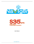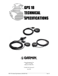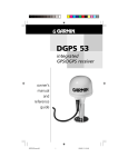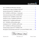
1
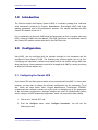
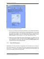
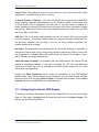
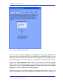
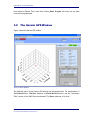
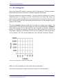
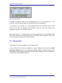
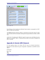
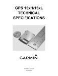
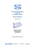
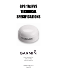
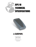
Particle Analysis and Display
System (PADS):
Garmin GPS Module
Manual
DOC-0288 Rev B
PADS 3.6.3
Garmin Module 3.7.1
2545 Central Avenue
Boulder, CO 80301 USA
COPYRIGHT © 2012 DROPLET MEASUREMENT TECHNOLOGIES,
INC
PADS Manual – Garmin GPS Module
Copyright © 2012 Droplet Measurement Technologies, Inc.
2545 CENTRAL AVENUE
BOULDER, COLORADO, USA 80301-5727
TEL: +1 (303) 440-5576
FAX: +1 (303) 440-1965
WWW.DROPLETMEASUREMENT.COM
All rights reserved. DMT licenses PADS software only upon the condition that you accept all of the
terms contained in this license agreement. Each PADS license you purchase allows you to acquire
data on one computer only. Data can be viewed in playback mode on an unlimited number of
computers.
This software is provided by DMT “as is” and any express or implied warranties, including, but not
limited to, the implied warranties of merchantability and fitness for a particular purpose are
disclaimed. Under no circumstances and under no legal theory, whether in tort, contract, or
otherwise, shall DMT or its developers be liable for any direct, indirect, incidental, special,
exemplary, or consequential damages (including damages for work stoppage; computer failure or
malfunction; loss of goodwill; loss of use, data or profits; or for any and all other damages and
losses).
Some states do not allow the limitation or exclusion of implied warranties and you may be entitled to
additional rights in those states.
Trademark Information
All Droplet Measurement Technologies, Inc. product names and the Droplet Measurement
Technologies, Inc. logo are trademarks of Droplet Measurement Technologies, Inc.
All other brands and product names are trademarks of their respective owners.
Risks of Installing Additional Software
Instrument computers from DMT are configured to acquire data in a reliable, robust manner.
Typically, such instruments are either not connected to a network or are connected to a small, local
network that is isolated from the internet, reducing the risk of viruses. Since anti-virus programs can
cause erratic behavior when run in the background on data acquisition computers, DMT does not
install anti-virus, anti-spam, or anti-malware programs. If you choose to install these programs, you
accept the risk associated with them in terms of potential performance degradation of the software
installed by DMT.
For similar reasons, DMT recommends that you do not install or run other software on the dedicated
instrument computer. Although the installation of some software may be unavoidable, it is particularly
important not to run other software while the computer is acquiring data.
Form DOC-0288 Rev B
© 2012 DROPLET MEASUREMENT TECHNOLOGIES, INC.
II
PADS Manual – Garmin GPS Module
CONTENTS
1.0
Introduction ........................................................................... 4
2.0
Configuration ......................................................................... 4
2.1
Configuring the Garmin GPS .............................................................. 4
2.1.1 Garmin GPS Parameters ............................................................... 5
2.2
Configuring the Garmin GPS Display ..................................................... 6
3.0
3.1
3.2
The Garmin GPS Window ........................................................... 8
3D Tracking Plot ............................................................................ 9
Channel Data ............................................................................... 10
List of Figures
Figure
Figure
Figure
Figure
Figure
Figure
1: Garmin GPS Configuration Editor Window ................................... 5
2: Garmin GPS Display Editor Window ........................................... 7
3: Garmin Window .................................................................... 8
4: 3-D Tracking Plot in “Latitude by Altitude” Mode ......................... 9
5: Scaling Controls .................................................................. 10
6: Data 2 Tab ........................................................................ 11
Form DOC-0288 Rev B
© 2012 DROPLET MEASUREMENT TECHNOLOGIES, INC.
III
PADS Manual – Garmin GPS Module
1.0
Introduction
The Particle Analysis and Display System (PADS) is a software package that interfaces
with instruments produced by Droplet Measurement Technologies (DMT) and other
leading instruments used in the atmospheric sciences. This manual describes the PADS
Garmin GPS module version 3.6.2.
For an explanation of the basic PADS setup and instructions on how to acquire data using
PADS, consult the PADS Overview Manual, DOC-0300. Definitions and calculations used in
the Garmin GPS module are also described in the PADS Overview
2.0
Configuration
Using PADS, you can configure both the software settings for the instrument and the
instrument’s data display in PADS. The following two sections explain how to do this.
Configuring the instrument’s software and display affects the default settings PADS uses
when starting up. Some parameters can also be changed while PADS is running, but doing
so affects the current session only.
2.1 Configuring the Garmin GPS
Your Garmin GPS and data system should arrive preconfigured from DMT. In some cases,
however, you may want to change the software configuration for the instrument. To do
this, follow the steps below. Note: Droplet Measurement Technologies STRONGLY
recommends that customers contact our office prior to changing any of the parameters
in the instrument configuration. Improper changes can result in communication failure
and/or changes in PADS computation algorithms, which can compromise data validity.
1. Click on the “Garmin GPS” tab.
2. From the Configure menu, select Configure Instrument. You will see the
following window.
Form DOC-0288 Rev B
© 2012 DROPLET MEASUREMENT TECHNOLOGIES, INC.
4
PADS Manual – Garmin GPS Module
Figure 1: Garmin GPS Configuration Editor Window
3. Now you can configure the instrument parameters to your desired specifications.
See the definitions below for explanations of individual parameters. If at any time
you would like to revert to the previously saved values for the Garmin GPS
parameters, press Cancel to exit the window without saving changes. Pressing
Reset Parameters reverts parameters to their DMT-supplied default values.
4. When you are done configuring the Garmin GPS parameters, press Save at the top
of the Config editor window. Then press the green Reset Program button for the
new configuration to take effect. Note that pressing the Reset Program button
will clear any data currently being displayed.
2.1.1
Garmin GPS Parameters
Instrument #: This lists the number corresponding to the instrument you are viewing, in
this case the Garmin GPS. If your Garmin GPS has been assigned instrument number one,
you will see “1” in this field. You should not need to modify the instrument number, and
in fact you are unable to do so from within PADS.
Form DOC-0288 Rev B
© 2012 DROPLET MEASUREMENT TECHNOLOGIES, INC.
5
PADS Manual – Garmin GPS Module
Sample Time: This parameter shows the time interval at which the Garmin GPS relays
sample data. It should always be set to 1 second.
At Startup Enabled / Disabled: If you want the Garmin GPS to acquire data when PADS
begins sampling, make sure this parameter is in the “Enabled” mode. In some cases, such
as if the Garmin GPS is inoperative, you may want to use this control to disable the
probe. Disabling the Garmin GPS allows data to transmit from other instruments without
interference. Data will still be written to the disabled instrument’s output file, but PADS
will write “NaN” to all fields.
COM Port: This is the serial communications port that the Garmin GPS uses to connect
with the computer. This number should match the computer hardware configuration for
the particular computer you are using. If you are not using multiple computers, this
number should not be changed.
Baud Rate: This parameter stores the baud rate for the probe. Although it is possible to
change the Garmin baud rate by using utility software supplied by Garmin, these units
are configured to a standard baud rate which should not need to be changed. Contact
DMT if you want to change the Baud rate.
Added Parameters Enabled? is a parameter that tells PADS whether the Garmin GPS has
additional parameters enabled. If this box is checked, the GPS will send additional
information to PADS that will be recorded in the PADS Garmin output file. For more
information, see Appendix B.
Pressing the Reset Parameters button resets all parameters to their DMT-supplied
default values. After making changes to the parameters, you will need to press the Save
button and then click the green Reset Program to activate these changes. Clicking Reset
Program will clear any data PADS is currently displaying.
2.2 Configuring the Garmin GPS Display
To configure the Garmin GPS display, click on the Garmin GPS tab if you have not already
done so. Then select Configure from the menu bar and click on Configure Display. This
will bring up the following window.
Form DOC-0288 Rev B
© 2012 DROPLET MEASUREMENT TECHNOLOGIES, INC.
6
PADS Manual – Garmin GPS Module
Figure 2: Garmin GPS Display Editor Window
You do not need to modify the Display # or Instrument #. Changing the Refresh Time
allows you to set the time intervals for data display during acquisition mode; you can
choose any time that is equal to or greater than the sample time. (Choosing a time less
than the sample time is not useful, since the same data will be displayed multiple times.)
Pressing the Reset Parameters button resets all parameters to their DMT-supplied
default values. After making changes to the parameters, you will need to press the Save
button and then click the green Reset Program to activate these changes. Clicking Reset
Program will clear any data PADS is currently displaying.
When you are done, click on Save to update the configurations or Cancel to revert to the
previous configuration. After you reset PADS, you will be able to see any changes you
Form DOC-0288 Rev B
© 2012 DROPLET MEASUREMENT TECHNOLOGIES, INC.
7
PADS Manual – Garmin GPS Module
have made to Refresh Time. Note that clicking Reset Program will clear out any data
currently being displayed.
3.0
The Garmin GPS Window
Figure 3 shows the Garmin GPS window.
Figure 3: Garmin Window
The different parts of the Garmin GPS Window are discussed below. For explanations of
the Enabled button, COM Port indicator, and Fault/No Fault button, see the “Instrument
Tabs” section of the PADS Overview Manual. The Status indicator is lit when
Form DOC-0288 Rev B
© 2012 DROPLET MEASUREMENT TECHNOLOGIES, INC.
8
PADS Manual – Garmin GPS Module
3.1 3D Tracking Plot
Most of the Garmin GPS window is devoted to the 3-D tracking plot. This plot provides a
three-dimensional view of the aircraft’s latitude, longitude, and altitude.
A red dot indicates the aircraft’s location. You can rotate the tracking plot in threedimensional space by clicking on the plot, holding down the mouse, and moving the
mouse around. Using the scroll button on your mouse will let you zoom in and out on the
plot. If you hold down the shift key and the left mouse button, you can change the plot’s
position in the window.
The boxed ViewMode indicator allows you to modify the tracking plot’s display. The
default mode is User Defined, which displays the view in three dimensions. ViewMode’s
other options project the 3D data onto two axes—longitude by latitude, altitude by
latitude, or altitude by longitude. Selecting one of these options has the effect of
temporarily “collapsing” the omitted axis as if you were looking at cubical space headon. For instance, “Alt x Lat” mode collapses the y-axis, longitude, as shown in Figure 4.
Figure 4: 3-D Tracking Plot in “Latitude by Altitude” Mode
When you rotate the display, the view returns to three dimensions.
The boxed controls shown in Figure 5 allow you to scale the 3-D Tracking Plot.
Form DOC-0288 Rev B
© 2012 DROPLET MEASUREMENT TECHNOLOGIES, INC.
9
PADS Manual – Garmin GPS Module
Figure 5: Scaling Controls
To enable autoscaling, click on the autoscale button if it is not currently on. It will
illuminate, and the controls above the autoscale button will be disabled.
If autoscaling is not enabled, two controls appear above the autsoscale button. These
allow you to enter the minimum and maximum values for the scale—latitude and
longitude in degrees, and altitude in meters.
Note that if Status = 0, indicating that current and valid data are not available, PADS
will recycle the most recent valid data until new readings become available. This is done
to ensure a proper scale for the 3-D tracking plot.
3.2 Channel Data
To the right of the 3D tracking plot are the channel data.
If your Garmin GPS has been configured to report additional data and the Added
Parameters Enabled? box on the Configuration Window (Figure 1) has been checked, the
Channel Data section will show additional channels will be displayed. These will appear in
a second tab, marked Data 2 (Figure 6).
Form DOC-0288 Rev B
© 2012 DROPLET MEASUREMENT TECHNOLOGIES, INC.
10
PADS Manual – Garmin GPS Module
Figure 6: Data 2 Tab
For definitions of both standard and additional Garmin channels, see Appendix A of DOC0300, the PADS Overview Manual.
The Satellite Link light indicates whether a successful GPS fix has been made. The light
will be on when the link is successful, meaning that enough satellites are visible to obtain
a fix.
As with the 3-D tracking plot, PADS will recycle the most recent valid data if current
data are not available. Status = 0 indicates that no valid current data are available and
PADS is recycling
Appendix A: Garmin GPS Channels
For each sampling instance, the Garmin GPS will return the channels listed below.
Definitions for these channels are given in Appendix A: Definitions in the PADS Overview
Manual.
End Seconds
Day of Year
Year
Status
Form DOC-0288 Rev B
© 2012 DROPLET MEASUREMENT TECHNOLOGIES, INC.
11
PADS Manual – Garmin GPS Module
GPS UTC time
Latitude
Longitude
quality
satellites
horiz precision
Antenna altitude(m)
Geoidal separation(m)
age of diff correction
Differ station ID
Checksum
Spare 1 - 8
UTC/GPS Time
Date
Time
Garmins that have Additional Parameters Enabled will report the following channels
after the channels listed above:
Receiver Status
Speed Over Ground (m/s)
Course Over Ground (deg)
UTC date (day)
UTC date (month)
UTC date (2-digit year)
Magnetic Variation (deg)
Magnetic Variation Direction
Mode Indicator
True East Velocity (m/s)
True North Velocity (m/s)
Up Velocity (m/s)
Garmin GPS channels fall into several broad categories:
Time Channels
GPS Data
Communications Data—information about the communication between 1.) the GPS
and satellites or 2.) the GPS and PADS
Form DOC-0288 Rev B
© 2012 DROPLET MEASUREMENT TECHNOLOGIES, INC.
12
PADS Manual – Garmin GPS Module
Appendix B:
Channels
Option for Additional Output
If your Garmin GPS has the additional channels feature, you will see additional data
channels displayed on the Data 2 tab of the Garmin GPS window. For these channels to
be available, the Added Parameters Enabled? box on the Configuration Window (Figure
1) must be checked. In addition, the Garmin GPS must be configured to report these
additional channels.
DMT normally will have configured the GPS unit to display the additional channels. It is
also possible, however, for the user to configure the GPS unit him or herself. This can be
done using Garmin’s SNSRXCFG.exe program1. This software enables the user to change
the NEMA sentences that the Garmin GPS reports.
In normal mode (Added Parameters Enabled? button unchecked) PADS looks for NEMA
sentence $GPGGA. In added channels mode (Added Parameters Enabled? button
checked), PADS looks for NEMA sentences $GPGGA, $GPRMC, $PGRMV.
Appendix C: Revisions to Manual
This document replaces DOC-0194, the Garmin GPS PADS Operator Manual for PADS
version 2.X.
1
The software is avaliable at
https://buy.garmin.com/shop/store/downloadsUpdates.jsp?product=010-0032131&cID=158&pID=27594. For a description of the software, see the Garmin GPS user’s manual
(Document #190-00879-08).
Form DOC-0288 Rev B
© 2012 DROPLET MEASUREMENT TECHNOLOGIES, INC.
13