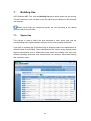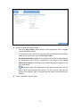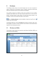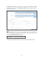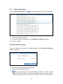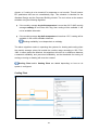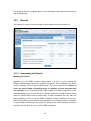
1
This page is intentionally left blank. ECOnirman Whole Building Performance USER MANUAL September 2011 ECOnirman Whole Building Performance USER MANUAL Developed by: USAID ECO-III Project International Resources Group 2 Balbir Saxena Marg, Hauz Khas, New Delhi, India Project Guidance Development Team Supporting Partners USAID/India Archana Walia International Resources Group, USAID ECO-III Project Aalok Deshmukh Sanyogita Manu Bibhash Das Harshitha Raju Satish Kumar Technical Consultants Vikas Arora Shruti Narayan Lata Iyer Bureau of Energy Efficiency Ajay Mathur Sanjay Seth Shabnam Bassi Girja Shankar Brijesh Manan The Weidt Group, Inc. (Software Design) Prasad Vaidya John Melchert Vinay Ghatti Phil Davis Chris Oace Paul Welter Dave Killion John Cherba Chris Baker Claire Stenroos Mark Bergass Michele Smeaton Alex Fritz The development of ECOnirman Whole Building Performance Tool and this User Manual are made possible by the support of the American People through United States Agency for International Development (USAID) under the terms of Award No. 386C-00-06-00153-00. Both are the sole responsibility of International Resources Group and do not necessarily reflect the views of USAID or the United States Government. How to use this manual The following symbols and icons are used in this user manual: Symbol/Icon Description § Section of the user manual * Mandatory field External web link Useful tip Caution or warning The text underlined in blue colour is a cross-reference within the user manual itself. In the soft copy, click it to open the section that is cross-referenced. Table of Contents 1. Introduction ............................................................................................. 1 2. Key Concepts .......................................................................................... 2 2.1. Energy Conservation Building Code (ECBC) .......................................... 2 2.1.1. 2.2. ECBC Tip Sheets ................................................................... 2 ECBC Conformance ............................................................................... 2 2.2.1. Mandatory Requirements ....................................................... 3 2.2.2. Prescriptive Method ................................................................ 3 2.2.3. Whole Building Performance Method ...................................... 3 Energy Simulation Software.................................................... 4 3. ECOnirman Whole Building Performance Tool .................................... 5 3.1. Modelling Protocol and Default Inputs..................................................... 5 3.2. Salient Features...................................................................................... 6 3.3. Prerequisites........................................................................................... 6 4. Tool Navigation ....................................................................................... 8 4.1. How to Access ........................................................................................ 8 4.2. Home Page............................................................................................. 9 4.3. User Account ........................................................................................ 10 4.3.1. New User.............................................................................. 10 4.3.2. Log In ................................................................................... 11 4.3.3. Retrieve Forgotten Password ............................................... 11 4.3.4. Change Password and Update Profile .................................. 13 4.3.5. Log Out................................................................................. 13 5. Manage Projects .................................................................................... 14 5.1. 5.2. Project Actions ...................................................................................... 15 5.1.1. Create Project....................................................................... 15 5.1.2. Edit Project ........................................................................... 15 5.1.3. Delete Project ....................................................................... 15 5.1.4. Copy Project ......................................................................... 16 Filter Project List ................................................................................... 17 6. Project Information ............................................................................... 18 6.1. General ................................................................................................. 18 6.2. Building ................................................................................................. 20 6.2.1. Building Shape ..................................................................... 21 6.2.2. Building Dimensions ............................................................. 22 6.2.3. Building Orientation .............................................................. 25 7. Building Use .......................................................................................... 26 7.1. Space Use ............................................................................................ 26 7.1.1. Area Allocation ..................................................................... 27 7.1.2. Lighting ................................................................................. 27 7.1.3. Loads ................................................................................... 28 7.1.4. Thermal Comfort................................................................... 30 7.1.5. Schedules............................................................................. 31 Season ................................................................................. 32 Days ..................................................................................... 33 Schedule .............................................................................. 33 7.2. Zoning .................................................................................................. 35 7.2.1. Floor Affinity ......................................................................... 36 7.2.2. Perimeter Allocation.............................................................. 36 8. Envelope ................................................................................................ 38 8.1. Windows and Walls .............................................................................. 38 8.1.1. Wall Construction ................................................................. 40 Customized Wall Assembly .................................................. 40 8.1.2. Window Construction ............................................................ 41 Customized Window Assembly ............................................. 41 8.1.3. Window Wall Ratio ............................................................... 42 8.1.4. Shading ................................................................................ 43 Horizontal Shading ............................................................... 43 Vertical Shading ................................................................... 44 8.2. Roofs and Skylights .............................................................................. 45 8.2.1. Roof Construction ................................................................. 45 Customized Roof Assembly .................................................. 46 8.2.2. Skylight Roof Ratio ............................................................... 47 8.2.3. Roof Reflectivity.................................................................... 47 9. Heating, Ventilation and Air Conditioning........................................... 48 9.1. Systems ................................................................................................ 49 9.1.1. Add System .......................................................................... 50 9.1.2. Edit System .......................................................................... 51 Air Systems .......................................................................... 51 Cooling Plant ........................................................................ 53 Heating Plant ........................................................................ 54 9.1.3. 9.2. Delete System ...................................................................... 55 Assignments ......................................................................................... 55 10. Conformance Check ............................................................................. 57 10.1. Mandatory Requirements ...................................................................... 57 10.2. Simulation ............................................................................................. 58 10.3. Results ................................................................................................. 59 10.3.1. Interpreting the Results......................................................... 59 Meeting the Loads ................................................................ 59 Energy Use and Energy Performance Intensity (EPI) ........... 60 10.3.2. Building Conformance Report ............................................... 61 11. Appendix A: Definitions and Acronyms .............................................. 62 11.1. Definitions ............................................................................................. 62 11.2. List of Acronyms ................................................................................... 68 12. Appendix B: Computer Settings .......................................................... 71 12.1. Web Browser ........................................................................................ 71 12.2. Conformance Reports ........................................................................... 72 1. Introduction The Ministry of Power, Government of India, under the provision of the Energy Conservation Act, 2001 launched the Energy Conservation Building Code (ECBC) in May 2007. Since then, the Bureau of Energy Efficiency (BEE) has been promoting the implementation of the ECBC through several capacity building programs. United States Agency for International Development (USAID) supported Energy Conservation and Commercialization - Phase-III (ECO-III) Project has been working closely with BEE on these initiatives, and has developed ECBC User Guide and ECBC Tip Sheets (§ 2.1.1) for raising awareness on the ECBC among the stakeholders. During these capacity building efforts, a strong need was felt to assist architects and engineers at the design stage so that they are able to assess and demonstrate conformance of their proposed buildings with respect to the ECBC. It is with this objective that the development of ECOnirman Whole Building Performance Tool, an online conformance check tool, was undertaken by ECO-III Project in partnership with BEE. The tool uses the Whole Building Performance (WBP) Method detailed in Appendix B of the ECBC to assess conformance. It is developed by The Weidt Group, Inc. (TWGI) under the guidance of ECO-III Project. This manual will familiarize a user with the interface of ECOnirman WBP Tool and walk through the step-by-step process of assessing conformance. 1 2. Key Concepts Before using ECOnirman WBP Tool for assessing conformance of the building, it will be beneficial to understand certain energy and conformance related concepts. These are explained in the following sub-sections. See Appendix A: Definitions and Acronyms (§ 11) for a list of definitions. 2.1. Energy Conservation Building Code (ECBC) The Energy Conservation Building Code (ECBC) is the result of extensive work by BEE and its Committee of Experts. Its purpose is to provide minimum requirements for energy efficient design and construction of commercial buildings and their systems. It is the first step towards promoting energy efficiency in the building sector. Refer to ECBC User Guide (International Standard Book Number 978-81909025-3-3, BEE, New Delhi, India) to understand the ECBC better. It is available online at http://eco3.org/?file_id=1 2.1.1. ECBC Tip Sheets The ECBC tip sheets created by ECO-III Project help in understanding the implications of the ECBC on different building components. The following four tip sheets are available for reference: Energy Simulation: http://eco3.org/?file_id=11 Building Envelope: http://eco3.org/?file_id=19 Building Lighting Design: http://eco3.org/?file_id=20 HVAC System: http://eco3.org/?file_id=25 2.2. ECBC Conformance The Bureau of Energy Efficiency‟s intention is to facilitate the design and construction of the buildings conforming with the ECBC in India. The conformance process has been made flexible enough to help designers and architects in meeting the ECBC requirements. Conformance with the ECBC can be achieved by meeting the mandatory requirements in the ECBC, in addition to either meeting the prescriptive requirements 2 using the Prescriptive Method (§ 2.2.2) or meeting the requirements in the Whole Building Performance Method (§ 2.2.3). 2.2.1. Mandatory Requirements The conformance procedure requires the building to fulfil a set of mandatory provisions related to energy use, as well as demonstrate conformance with the specified requirements stipulated for the different building components and systems. 2.2.2. Prescriptive Method The Prescriptive Method of conformance specifies prescribed minimum energy efficiency parameters for various components and systems of the building. Conformance with the ECBC can be achieved by meeting or exceeding the specific levels described for each individual element of the building systems. Refer to ECOnirman Prescriptive Tool User Manual (available online at http://eetools.in/ECOnirman_Prescriptive_UserManual.pdf ) to assess conformance using the Prescriptive Method. 2.2.3. Whole Building Performance Method The Whole Building Performance (WBP) Method offers considerable design flexibility and allows for conformance with the ECBC to be achieved by optimizing the energy used by various components and systems in order to find the most effective solution. The WBP Method requires the use of an energy simulation software approved by the Authority Having Jurisdiction to simulate and compare energy use of the Proposed Design and the Standard Design of the building. Appendix B of the ECBC prescribes the protocol for developing a computer-based model for the purpose of energy simulation of the Proposed Design and the Standard Design of the building. Energy consumption of the Standard Design is the upper limit of energy use allowed for that particular building that meets all the prescriptive requirements applicable to that building. The conformance is achieved if the energy consumption of the Proposed Design is no greater than the energy consumption of the Standard Design. The following are the basic steps involved: Design the building with energy efficiency measures; the prescriptive approach requirements provide a good starting point for the development of the design. Meet the applicable mandatory requirements of the ECBC. 3 Simulate the energy use of the building using the software approved by the Authority Having Jurisdiction. This is to be done by following the protocol in Appendix B to simulate the Proposed Design and the Standard Design. Compare the simulated energy use of the Proposed Design and the Standard Design. If the energy consumption of the Proposed Design is no greater than the energy consumption of the Standard Design, the building conforms with the ECBC. Energy Simulation Software The use of energy simulation software is necessary to show conformance with the ECBC using the WBP Method. Energy simulation is a computer-based analytical process that helps building owners and designers to evaluate the energy performance of a building before it is built and operated. The energy simulation software can model the thermal, visual, ventilation, and other energy consuming processes taking place within the building to predict its energy performance. The software takes into account the building geometry and orientation, materials, façade design and characteristics, climate, indoor environmental conditions, occupant activities and schedules, Heating Ventilation and Air Conditioning (HVAC), lighting system, and other parameters to simulate the energy performance of the building. Refer to Energy Simulation tip sheet available at http://eco3.org/?file_id=11 to learn more about building energy simulation. 4 3. ECOnirman Whole Building Performance Tool ECOnirman Whole Building Performance Tool is an energy simulation software provided by BEE to assist architects and engineers in assessing the conformance of their buildings with the ECBC using the WBP Method. It is a web-based tool that is made available to the users over the Internet with minimal software requirements, building science, or simulation expertise. With minimal learning involved, a user having knowledge equivalent to that of a fifth-year architecture student with access to about one hour of HVAC engineer‟s time, can use the tool to demonstrate conformance with the ECBC. A total of 1,294 city locations in India are represented in the tool. It has 46 weather files. Each city location and weather file has been assigned to the climate zone that it falls within on the basis of Geospatial Information System (GIS) mapping of the climate zones and the cities. When a city location for the building is chosen, the tool finds the closest available weather file within the same climate zone. This weather file is selected for the simulation. The tool requires inputs about the building from the user. Based on the inputs, it runs simulation of the Proposed Design and the Standard Design as per Appendix B of the ECBC, and compares the Energy Performance Intensity (EPI) of simulation results. The results are presented after the simulation is completed. The tool also generates a report that may be submitted to the Authority Having Jurisdiction to demonstrate conformance with the ECBC. Energy Performance Intensity (EPI) is defined as the annual energy consumption measured in kWh per square meter of the built-up area of the building. It is the ratio of the total energy used to the total built-up area and is expressed as kWh/m2/year. 3.1. Modelling Protocol and Default Inputs ECOnirman WBP Tool follows the modelling protocol of Appendix B of the ECBC for developing the models of the Standard Design and the Proposed Design. The following logic is used: The details of the building are entered and the Proposed Design and the Standard Design are developed accordingly in the background as per the rules in Appendix B of the ECBC. 5 Example: The user selects Daytime use or 24-hours use of the building and enters insulation values of the building materials. The tool determines the insulation values for the Standard Design based on the usage information entered and uses the material insulation values for the Proposed Design. The tool provides the defaults for the Proposed Design if its details are not specified by the user. These defaults are the same as those for the Standard Design. These defaults are provided across the tool for convenience only. It is important to provide actual building inputs to run the simulation correctly for assessing conformance. 3.2. Salient Features ECOnirman WBP Tool ECOnirman Prescriptive Tool indicates if the systems and sub-systems of the building are conforming or not conforming with the ECBC and also generates a conformance report that compile the data provided by the user. It facilitates the users in assessing if a building meets the ECBC requirements vis-à-vis the five climatic zones in India. It can store multiple building projects under a single user profile. It stores the information in a central database for future reference, review, edit, and analysis purposes. It keeps the information secure and confidential. It allows the design teams to collaborate remotely. It is available in the public domain (http://econirmanwbp.eetools.in ) for easy access to the users. 3.3. Prerequisites The following checklist of items (specific to the building being assessed for conformance) will come in handy while using ECOnirman WBP Tool: Total interior floor area Marked-up plans by space types (see illustrations in § 7.2.2) Floor area for each space type Perimeter lengths for each space type Lighting Power Density (LPD) values for each space type 6 Space types marked as conditioned or unconditioned Ventilation requirements Mechanical equipment sizes and efficiencies Pump and fan static pressures Envelope construction assemblies (for walls, roofs, windows, and skylights) and shading 7 4. Tool Navigation ECOnirman WBP Tool is aesthetically designed, keeping in mind the ease of navigation for the end-user. The tool features different tabs at the top to navigate effectively through a project. These tabs feature sub-tabs (on the left side) that act as logical sections to enter the relevant building details to run the simulation and generate the conformance report. For each building project, the user progresses by specifying the parameters including building shape, dimensions, orientation, building use information, and details of the HVAC systems. When complete, the simulation can be invoked to view the results for both the Standard Design and the Proposed Design. The tool allows the user to provide inputs for the simulation that do not need to be sequential. The information can be provided in the sequence preferred by the user. This makes it more intuitive and interactive. However, to get correct results, the user needs to go through all the left side sub-tabs under each top tab and provide the information relevant to the building. Across the tool, the fields marked with an asterisk (*) are mandatory. 4.1. How to Access Enter the link http://econirmanwbp.eetools.in in the web browser's address bar to access ECOnirman WBP Tool. See Appendix B: Computer Settings (§ 12) to learn about the settings required on a user‟s computer before using the tool. 8 4.2. Home Page The following illustration highlights the composition of ECOnirman WBP Tool home page. A. Click About to view the tool version and credits; click Help to view this user manual B. Enter the user credentials and click Login to assess if a building and its components conform with the ECBC using the WBP Method (see § 4.3.2) C. Click Request Login to register as a new user (see § 4.3.1) D. Click Forgot Password? to retrieve a forgotten password (see § 4.3.3) 9 4.3. User Account This section explains how to create a new user account, log into the tool, retrieve a forgotten password, update user profile, and change a password. 4.3.1. New User Click Request Login on the home page to register as a new user. The Request Login dialog box appears. Enter a valid e-mail address. Enter a desired password and confirm it. The password is case sensitive. Enter name and other details. Click Submit to create the user account. The Projects page opens. See § 5 to learn how to manage projects. If an e-mail address is unavailable or invalid, a message appears at the top of the page. Enter another e-mail address. 10 4.3.2. Log In For an existing user, enter the registered e-mail address and password on the home page. The password is case sensitive. Click Log In to log into ECOnirman WBP Tool. The Projects page opens. See § 5 to learn how to manage projects. 4.3.3. Retrieve Forgotten Password A forgotten password can be retrieved from any of the following two locations: Request Login dialog box (see § 4.3.1 New User) Log In dialog box (see § 4.3.2 Log In) On the dialog box, click Forgot Password? to retrieve the password of an existing user. The Forgot Password dialog box appears. 11 Enter the registered e-mail address. Click Submit to send the request for password retrieval to the registered e-mail address. Open the e-mail (external of ECOnirman WBP Tool) and click the hyperlink available therein. The Reset Password dialog box appears in ECOnirman WBP Tool with the reset key auto-populated. Enter the new password and confirm it. Click Submit to reset the password. 12 4.3.4. Change Password and Update Profile Click on logged in user‟s e-mail address at the top right corner of the page to change the password or update the user details. The Update Profile dialog box appears. To change the password, enter the new password, confirm it, and click OK. To update the profile, enter the relevant details and click OK. 4.3.5. Log Out After using ECOnirman WBP Tool, click Logout at the top right corner of the page to log out. It is imperative to save the entered details before logging out. Any unsaved details will be otherwise lost. 13 5. Manage Projects After logging into ECOnirman WBP Tool for the first time, a blank project list is displayed. However, if the project records were already created by an existing user by logging in earlier, then those are listed. A. Actions: Create new project (see § 5.1.1) Existing project: Edit (see § 5.1.2) Delete (see § 5.1.3) Copy (see § 5.1.4) B. Filter the list of projects (see § 5.2) C. The list of projects The project list can be sorted by clicking the column heading. For example, click the column heading Has Results to view the projects sorted as per the availability of the simulation result. Yes indicates that simulation results are available for the project and No indicates that they are not. 14 5.1. Project Actions The building projects can be created, edited, deleted, and copied. These actions are explained in the following sub-sections. 5.1.1. Create Project To create a new project for assessing conformance, click New at the top right corner of the page. The Project Information tab opens (see § 6). 5.1.2. Edit Project To edit an existing project, click on a project in the list and then click Edit at the top right corner of the page. The Project Information tab opens with the underlying project details (see § 6). 5.1.3. Delete Project To delete an existing project, click on a project in the list and then click Delete at the top right corner of the page. A confirmation dialog box appears. Click Yes to delete the project. The project gets deleted. There is no way to undo this action and retrieve a deleted project. 15 5.1.4. Copy Project To make a copy of an existing project, click on a project in the list and then click Copy at the top right corner of the page. The General sub-tab (§ 6.1) under the Project Information tab opens. The project name in the Project Name field is suffixed with the word „Copy‟. Change this, if required. Click Save at the top right corner of the page. A copy of the project is created with all the information from the original project retained as is. 16 5.2. Filter Project List The projects in the list can be filtered to view only the relevant ones. This feature is particularly useful as the number of projects increase and the list gets bigger. The following two date filters are available: Last Modified Date The date on which an existing project was last modified Creation Date The date on which a new project was created Select the radio button corresponding to the desired date filter. Define the date range: To set the start date, click corresponding to Start. Select the date from the calendar that appears. To set the end date, click corresponding to End. Select the date from the calendar that appears. Click or to navigate to the previous or the next calendar month respectively. Finally, click Apply Filter to set the filter. Only the projects within the defined date range get listed. Select No Filter radio button to remove the set filter. 17 6. Project Information The Project Information tab opens upon clicking New, Edit, or Copy on the Projects page. The tab comprises of two sub-tabs on the left side that are explained in the following sub-sections. Certain input fields get customized across the tool according to the details entered under these sub-tabs. 6.1. General This sub-tab is used to capture the name, location, and basic information of the building. It is important to enter correct information under this sub-tab before proceeding any further. Making changes on this sub-tab after providing inputs elsewhere in the tool will reset the defaults for the project. All the inputs across the tool will be lost for that project. Enter/edit the details such as project and organization names, location details, building type and occupancy, and dimensions. 18 Enter the exact Total Interior Floor Area of the building. Certain input fields get defaulted across the tool based on this information. Click Apply at the bottom of the page. At this point: The creation and modification dates along with the timestamps are displayed. Other tool tabs and sub-tabs get activated. Revert (at the bottom of the page) is used to discard the entered details and revert to the previously saved ones. Click Return to Project List at the top right corner of the page at any point to access the list of projects. A dialog box appears to save the project. Click Yes to save. It is imperative to save the project before accessing the list of project. Any unsaved project details under the tabs/sub-tabs will be otherwise lost. 19 6.2. Building This sub-tab is used to define the shape, dimensions, and orientation of the building. The building geometry inputs can be specified by selecting a building floor plan shape and modifying the proportions and orientation to represent the building to be assessed for conformance. To keep the inputs easy, five typical building plan shapes are provided in the tool (see § 6.2.1). A shape can be customized by modifying the building dimensions (see § 6.2.2). Also, the orientations can be defined at 45° increments by rotating the shape (see § 6.2.3). 20 6.2.1. Building Shape Select the shape of the building from the available five options. 21 6.2.2. Building Dimensions The dimensions are displayed on the basis of the selected building shape. Change the values to customize the dimensions. If the calculated area while customizing the dimensions does not reconcile with that defined under the General sub-tab (§ 6.1), a warning icon is displayed. To resolve: Hover the mouse pointer over the icon to read the warning message. It displays Total Building Area Specified and Building Area Calculated from Dimensions. Assess the variance. 22 Make appropriate corrections so that the area calculated from the dimensions matches with that defined under the General sub-tab (§ 6.1). The building shape in the center of the page changes dynamically in proportion to the customized dimensions. 23 The following are certain examples of building shapes derived by modifying the dimensions: 24 6.2.3. Building Orientation The orientation of the building can be defined by rotating the building clock-wise at 45° intervals. To rotate, click the white arrow and simultaneously drag the mouse pointer clock-wise. The building can be oriented in the following eight cardinal/ordinal directions: North North-East East South-East South South-West West North-West 25 7. Building Use In ECOnirman WBP Tool, click the Building Use tab to define space use and zoning. The tab comprises of two sub-tabs on the left side that are explained in the following sub-sections. Certain input fields get customized across the tool according to the details entered under these sub-tabs. 7.1. Space Use This sub-tab is used to define the area allocated to each space type and the corresponding loads, lighting details, thermal comfort, and operating schedules. A key task in modelling the Proposed Design is assigning space use classifications to different areas of the building. These classifications are used to assign lighting power density assumptions and to differentiate areas within the building that may have different operating schedules and characteristics (for example, thermostat settings and ventilation rates). 26 Some space types are defaulted to be unconditioned, which can be modified. Unconditioned zones are modelled identically in the Standard Design and the Proposed Design models. The following is the modelling method: All unconditioned thermal zones have their cooling set points as 50°C and heating set points as 8°C. All unconditioned thermal zones are assigned to one air handling unit (AHU). Thus, the cooling and the heating for the AHU with unconditioned zones are not activated by the simulation engine in the simulation run. 7.1.1. Area Allocation Against each space type, enter the area to be allocated to it under the Allocated Area (m2) column. The total area allocated to all space types must be equal to the Total Interior Floor Area defined under the General sub-tab (§ 6.1). If it is higher or lower, the variance is displayed. 7.1.2. Lighting Click Edit corresponding to a space type to edit its lighting details. The Edit Space Type dialog box appears with the default lighting details. It is important to replace the defaults with the inputs that match the actual building design in order to get the correct simulation results for conformance. 27 Define lighting power density (LPD). Enter the details of lighting controls. Click OK to set the lighting details. 7.1.3. Loads Click Edit corresponding to a space type to edit its loads. The Edit Space Type dialog box appears. Click the Loads tab. Enter these loads to get a more accurate prediction of the overall energy use of the building. In case of a doubt, leave the defaults in place. These loads are identical in both the Proposed Design and the Standard Design models, and therefore do not influence the energy efficiency of the design. 28 Define the plug and process loads. Enter the Plug Loads (power density for the equipment that is plugged into the electrical outlets). For equipment that uses forms of energy other than electricity and release heat into the space type, enter the Process Loads. Sensible heat load to space is the cooling load caused by heat added to the space that causes the air temperature in that space to rise. Latent heat load to space is the cooling load caused by adding moisture to the air in that space. Both these loads are percentages of the total process load, and the sum of both cannot exceed 100 percent. The sum may be less than 100 percent (for example, part of the load may be directly exhausted from a kitchen). Finally, click OK to set the loads. 29 7.1.4. Thermal Comfort According to Appendix A of the ECBC, the floor area of a building is categorized as following: Conditioned space: This is a cooled space, heated space, or directly conditioned space in the building. Semi-heated/cooled space: This is an enclosed space within a building that is heated by a heating system whose output capacity is greater than or equal to 10.7 W/m2 of floor area but is not a conditioned space. Unconditioned space: This is neither conditioned space nor semi-heated space. Crawl spaces, attics, and parking garages with natural or mechanical ventilation are not considered as enclosed spaces. Click Edit corresponding to a space type to edit its thermal comfort details. The Edit Space Type dialog box appears. Click the Thermal Comfort tab. Define people related details. Leave the defaults in place if this information is not available. Define conditioned space details (optional) such as thermostat settings, humidity control, and ventilation requirements. 30 It is important to replace these defaults with the inputs that match the actual building design in order to get the correct simulation results for conformance. Click OK to set the thermal comfort. 7.1.5. Schedules Schedules are used to define an hour-by-hour value that represents the percentage of the maximum internal load. It applies to lighting power density, miscellaneous equipment (plug load or process load) power density, and building occupancy. Schedules can have a large impact on energy consumption. The user needs to specify weekday (Monday-Friday) and weekend (Saturday and Sunday) operations in each schedule. ECOnirman WBP Tool simulates the Proposed Design and the Standard Design with identical schedules. Click Edit corresponding to a space type to edit its operating schedules. The Edit Space Type dialog box appears. Click the Schedules tab. 31 Season Select a season from the drop-down menu. Regular (Default) is the default season, which cannot be deleted. To create a new season, click New. The Add New Season dialog box appears. Enter the name of the season. Define the period (start and end months/days). Click OK. To edit a season, select it from the drop-down menu and click Edit. The Edit Season dialog box appears. Make the changes and click OK. To delete a season, select it from the drop-down menu and click Delete. A confirmation dialog box appears. 32 Click OK to delete the season. The season gets delisted from the drop-down menu. Days Toggle between Weekday (Monday-Friday) and Weekend (Saturday and Sunday) tabs to view the corresponding schedules. Schedule The schedule is plotted for the following four categories: Occupancy Lighting Plug Load Process Load Select a category to view its pattern during the 24 hours of the day. 33 The selected category is represented by a solid line, whereas the other three are represented by dotted lines. Select hour-based data point(s) and drag the mouse pointer to change the pattern. Click Select All to select all the data points (all 24 hours). Click Unselect All to unselect the selected data point(s). Select hour-based data point(s) and right-click on the mouse. A context menu appears. Select a category under Match the schedule to match the selected hourbased data point(s) to that category‟s hour-based data point(s). Select 0% to set the selected hour-based data point(s) to 0%; select 100% to set the selected hour-based data point(s) to 100%; select Custom Percentage to define a customized percentage for the selected hourbased data point(s). 34 7.2. Zoning This sub-tab is used to provide the information to generate the thermal zones of the building. ECOnirman WBP Tool uses the building geometry (shapes, dimensions, and orientations), the specified space types, and zoning affinities to create the zones for both the Proposed Design and the Standard Design models. In ECOnirman WBP Tool, click the Zoning sub-tab to define the zones. The pre-populated perimeter lengths are provided for convenience only. It is important to provide the inputs that represent the actual building to create the zones correctly. 35 7.2.1. Floor Affinity Select Floor Affinity (Any, Ground, Top) for a space type from the drop-down menu adjacent to it. Any: This sets the zone(s) of the space type be placed on any floor within the building Ground: This sets a priority for the zone(s) of the space type to be placed on the ground floor of the building. Top: This sets a priority for the zone(s) of the space type to be placed on the upper level, or the top floor of the building. 7.2.2. Perimeter Allocation Click Apply Defaults to set the default values for the space types for the selected building shape vis-à-vis the area allocated under the Building sub-tab (§ 6.2). However, if this is clicked after any changes are made under the Zoning subtab, then those changes will be lost and the defaults will be re-applied. Perimeter orientation affinities: Perimeter zones in the model need to reflect the perimeter space types that are along the exterior walls in the building. To achieve this: Mark up the plans to classify the rooms by space types (see example below). Mark up the perimeter lengths of the spaces. Add the total length of a space type along each orientation and enter the sum in the zoning table in the tool. Example: The following are the illustrations of a 3-storied building with its plans marked up as space types along with the dimensions of the length occupied by each space type on the perimeter. 36 The following table depicts how floor affinities and perimeter affinities are calculated from the plans above. Floor Affinity: Since Lobby and Storage are only on the ground floor, they get Ground as the floor affinity. Medium Conference is only on the top floor, so it gets Top as the floor affinity. Perimeter Affinity: For each orientation, add up the linear exposed length for a space type and enter it in the corresponding cell in the tool. On the South face, the circulation has 30 m on the first floor and 30 m exposed on the second floor. Therefore, the perimeter affinity for Circulation on the South is 30 m + 30 m = 60 m. 37 8. Envelope The building envelope refers to the exterior façade and roof, and is comprised of opaque components and fenestration systems. Opaque components include walls and roofs; fenestration systems include windows and skylights. The envelope protects the building‟s interior and occupants from the weather conditions and shields them from other external factors such as noise and air pollution. Envelope design strongly affects the visual and thermal comfort of the occupants, as well as the energy consumption of the building. Refer to Building Envelope tip sheet available at http://eco3.org/?file_id=19 to learn more about envelope. In ECOnirman WBP Tool, click the Envelope tab to define the windows, walls, roofs, and skylights of a building. The tab comprises of two sub-tabs on the left side that are explained in the following sub-sections. 8.1. Windows and Walls This sub-tab is used to define the construction and Window Wall Ratio (WRR), and vertical and horizontal shading. 38 Click Edit above a direction (north, east, south, or west) to edit the details of windows and walls for that direction. The Windows and Walls dialog box appears with prepopulated default values. The changes made for a direction (for example, north) can be replicated for other direction(s) (east, south, west) by selecting the relevant check boxes at the bottom of the Windows and Walls dialog box. The following sub-sections explain how to edit the details of windows and walls. 39 8.1.1. Wall Construction To change Wall Construction, click to view the drop-down list of wall assemblies. Select the desired assembly. If required, make other changes on the Windows and Walls dialog box. Finally, click OK. Customized Wall Assembly To add a customized assembly, click Add Custom. The Custom Wall Material dialog box appears. Enter the name of the customized assembly. Enter the corresponding U-factor. This is an assembly U-factor that includes the effect of air-film on both sides of the wall; this value is not always calculated as the sum of the thermal resistance properties of the wall layers. If required, consult the insulation or 40 building material manufacturer and ask for a calculation of the assembly Ufactor. Click OK. The customized assembly gets listed in the drop-down list with the word „Custom‟ prefixed to it. If required, make other changes on the Windows and Walls dialog box. Finally, click OK. 8.1.2. Window Construction To change Window Construction, click to view the drop-down list of window assemblies. Select the desired assembly. If required, make other changes on the Windows and Walls dialog box. Finally, click OK. Customized Window Assembly To add a customized assembly, click Add Custom. The Custom Window dialog box appears. 41 Enter the name of the customized assembly. Enter the corresponding glazing assembly U-factor. This is not the centre of glass U-factor that is listed in the glass manufacturer‟s catalogue. To get the U-factor of the overall fenestration product, contact the glass manufacturer and ask for it based on the average size of the window units. Enter solar heat gain coefficient. Enter visible light transmittance. Click OK. The customized assembly gets listed in the drop-down list with the word „Custom‟ prefixed to it. If required, make other changes on the Windows and Walls dialog box. Finally, click OK. 8.1.3. Window Wall Ratio This is the ratio of the vertical fenestration (window) area to gross exterior wall area. The gross exterior wall area is measured horizontally from the exterior surface; it is measured vertically from the top of the floor to the bottom of the roof. The HVAC engineer for the building is likely to have this information. On the Windows and Walls dialog box: Enter Window Wall Ratio. Make other changes, if required. 42 Finally, click OK. 8.1.4. Shading The overhangs on a building can reduce solar gains. The inputs for both horizontal shading devices and vertical fins that extend out of a building can be provided in the tool. Horizontal Shading Select Horizontal Shading check box to enter its details. See the illustration above to understand the input fields. Enter the following details: The extension (in meters) of the overhang from the building. The distance (in meters) of the overhang from the window. The height (in meters) of the windows. The transparency of the horizontal shading. If required, make other changes on the Windows and Walls dialog box. Finally, click OK. 43 Vertical Shading Select Vertical Shading check box to enter its details. See the illustration above to understand the input fields. Enter the following details: The extension (in meters) of the overhang from the building. The interval (in meters) between the fins. The transparency of the vertical shading. If required, make other changes on the Windows and Walls dialog box. Finally, click OK. 44 8.2. Roofs and Skylights This sub-tab is used to define the construction of building roofs, the skylight roof ratio (SRR), and the roof reflectivity. The following sub-sections explain how to edit the details of roofs and skylights. 8.2.1. Roof Construction To change Roof Construction, click to view the drop-down list of roof assemblies and select the desired one. 45 Customized Roof Assembly To add a customized assembly, click Add Custom. The Custom Roof Material dialog box appears. Enter the name of the customized assembly. Enter the corresponding U-factor. This is an assembly U-factor that includes the effect of air-film on both sides of the wall; this value is not always calculated as the sum of the thermal resistance properties of the wall layers. If required, consult the insulation or building material manufacturer and ask for a calculation of the assembly Ufactor. Click OK. The customized assembly gets listed in the drop-down list with the word „Custom‟ prefixed to it. 46 8.2.2. Skylight Roof Ratio This is the ratio of the total skylight area of the roof, measured to the outside of the frame, to the gross exterior roof. Enter Skylight/Roof Ratio. 8.2.3. Roof Reflectivity As per the ECBC, for the Standard Design, exterior roof surfaces, other than those with ventilated attics, must be modelled assuming a surface reflectance value of 0.30. However, if a Proposed Design calls for a reflective roof surface, the model may assume a long-term average reflectance of 0.45. This results in lower heat absorption of the reflective surface and makes a conservative allowance for the degradation of reflectivity over its lifetime. For this exception to be allowed, the specified reflectance of the roof in the Proposed Design must exceed 0.70 and its emittance must exceed 0.75. Enter Roof Reflectivity. 47 9. Heating, Ventilation and Air Conditioning Heating, Ventilation and Air Conditioning (HVAC) refers to the equipment, distribution systems, and terminal units that fulfil, either collectively or individually, the heating, ventilation, or air-conditioning requirement of a building or a portion of it. HVAC systems account for a significant portion of a commercial building‟s energy use. HVAC energy use can increase or decrease significantly depending on how efficiently the air side systems and central plant operate. Proven technologies and design concepts can be used to build efficiencies in the systems and generate significant energy and cost savings. An optimal HVAC design considers all the interrelated building systems while addressing indoor air quality, thermal comfort, energy consumption, and environmental benefits. HVAC systems broadly comprise of Air Systems, Cooling Plant, and Heating Plant. The following is the list of HVAC systems: Name Characteristics Central Plant VAV Central Variable Air Volume (VAV) AHU with cold and hot water loops from a central chiller and a boiler plant Central Plant Constant Central constant volume reheat AHU with cold and hot Volume water loops from a central chiller and boiler plant Packaged VAV Packaged VAV system with direct-extension (DX) coil Packaged Rooftop CAV Packaged constant volume system with DX coil Split system Split systems, high wall or cassette type Through-wall system Mounted through the wall, typically in hotels Window unit Unitary window mounted units This is a single zone system, where each thermal zone will be assigned a separate system. Refer to HVAC System tip sheet available at http://eco3.org/?file_id=25 to learn more about HVAC. In ECOnirman WBP Tool, click the HVAC tab to define HVAC systems and assign them to different space types or zones. The tab comprises of two sub-tabs on the left side that are explained in the following sub-sections. 48 Certain input fields get customized across the tool according to the details entered under these sub-tabs. 9.1. Systems This sub-tab is used to add new HVAC systems and edit them. The default system that appears will be modelled in the Standard Design. If this is the system in the Proposed Design, then edit its inputs. To change the systems to match the Proposed Design, add other systems (§ 9.1.1) to match those in the building and delete the default system shown by the tool (§ 9.1.3). Select Hot Water Service under Settings at the bottom of the page if the building has water heating facility. 49 9.1.1. Add System Click Add to add a new system. The Add HVAC Air System dialog box appears. Select the system from Air System Type drop-down menu. Click OK. The system gets listed under Air Systems. Cooling Plant and/or Heating Plant are added by the tool automatically if a system with a plant is added. 50 9.1.2. Edit System To edit a system, click Edit adjacent to its name. The diagram of the system and its properties appear. Air Systems Specify the following properties (customizable inputs) of the air system: Air System Type Properties Central Central Packaged Packaged Split Through Window (Custom Plant Plant VAV Rooftop System -wall Unit Inputs) VAV Constant CAV System Volume Air System Inputs System Name Air Flow Sizing Maximum Supply Air Flow (l/s) Use 51 Air System Type Properties Central Central Packaged Packaged Split Through Window (Custom Plant Plant VAV Rooftop System -wall Unit Inputs) VAV Constant CAV System Volume Seasonal Schedule Cooling Coil Cooling Source Heating Coil Heating Source Supply Fan Location Static Pressure (Pa) Return Fan Static Pressure (Pa) Outside Air Control Economizing Exhaust Air Heat Recovery Type Terminal Units Includes Reheat Coil Source After specifying the properties, click OK to define the air system. Cooling and Heating Availability Schedules: The tool gives an option to select seasonal availability of heating and cooling for each individual HVAC system included in the building. If the seasonal availability is not selected by the user, the tool allows heating and cooling to be available through the entire year. Select the seasonal option if heating is to be turned off in the non-winter months in a cold 52 climate, or if cooling is to be turned off in temperate or cool months. This will ensure EPI predictions that are not unrealistically high. This schedule is identical for the Standard Design and the Proposed Building models. The tool arrives at the season schedule using the following algorithm: If the monthly average dry-bulb temperature is more than 26°C AND monthly average enthalpy is more than 60 kJ/kg, then cooling will be available. It will not be available otherwise. If the monthly average dry-bulb temperature is less than 15°C, heating will be available. It will not be available otherwise. Heating availability is not dependent on enthalpy. The above algorithm results in operating the systems for heating and cooling when the monthly average values fall outside the comfort range according to ISO 77301993. In some places like Mumbai, this algorithm will result in no difference between a seasonal availability and year-round availability, as the thresholds for turning off cooling or turning on heating will never be crossed. Cooling Plant and/or Heating Plant are added depending on how an air system is configured. Cooling Plant 53 Specify the following properties (customizable inputs) of the cooling plant: Cooling System Inputs Chiller(s) Cooling Tower Primary Pump Secondary Pump Condenser Pump Finally, click OK to define the cooling plant. Heating Plant Specify the following properties (customizable inputs) of the heating plant: Heating System Inputs Boiler Primary Pump Secondary Pump Finally, click OK to define the heating plant. 54 9.1.3. Delete System To delete a system, select it and click Delete. A confirmation dialog box appears. Click Yes to delete the system. The system gets deleted. There is no way to undo this action and retrieve a deleted system. 9.2. Assignments As per the ECBC, HVAC Zone is a space or group of spaces within a building with heating and cooling requirements that are sufficiently similar so that the desired conditions (for example, temperature) can be maintained throughout using a single sensor such as thermostat or temperature sensor. A zone represents an area catered to by one air conditioning unit. With the help of zoning, building plans are simplified to reduce the modeller‟s work. Normally, usage pattern, set point temperature, and other conditions are identical within one zone. The building spaces that would experience similar heating and cooling loads are generally grouped under one zone. ECOnirman WBP Tool lists all the resulting zone types for each space type and allows assigning different HVAC systems to them individually or as a group for an entire space type. This allows the user to appropriately assign different HVAC systems to the perimeter zones and the core zones, and different HVAC systems to different perimeter zones. This sub-tab is used to assign HVAC systems to different space types or zones. 55 A combination of perimeter (by orientation) and core zones are created by the tool depending on the user inputs under the Zoning sub-tab (§ 7.2). Assign the system to the space type by selecting the corresponding radio button. Click adjacent to a space type to expand or collapse the tree structure in order to make HVAC system assignments at a detailed level by perimeter and orientation. 56 10. Conformance Check ECOnirman WBP Tool provides the conformance assessment result with a detailed report. The information in the report can be used for analysis and subsequent improvement of the building performance. This report can also be submitted to the Authority Having Jurisdiction. Click the Conformance Check tab to respond to the mandatory requirements of the ECBC, run the simulation, and view the conformance results. The tab comprises of three sub-tabs on the left side that are explained in the following sub-sections. 10.1. Mandatory Requirements This sub-tab is used to respond to the questions related to the mandatory requirements of the ECBC to assess a building‟s conformance. The responses to all the mandatory requirements have to be either Yes or not applicable (NA) for the building to conform with the ECBC. The building will be nonconformant if the response to even one mandatory requirement is No. 57 10.2. Simulation This sub-tab is used to run the simulation for the Proposed Design vis-à-vis the Standard Design to assess conformance of the building with the ECBC. Click Run to initiate the simulation. A dialog box appears to save the project if there are unsaved changes. Click Yes to save. It is imperative to save the project before running the simulation. Any unsaved project details under the tabs/sub-tabs will be otherwise lost. The simulation starts. 58 The progress bar, time elapsed, status of the simulation, and issues encountered (if any) are displayed. 10.3. Results This sub-tab is used to view the results of the simulation at the end of the run. 10.3.1. Interpreting the Results Meeting the Loads Appendix B of the ECBC contains requirements in § 10.3.2 (e) for meeting the building loads through sizing of the systems and plants. The tool displays the results of the simulation vis-à-vis these requirements. The unmet load hours (number of hours any zone outside of throttling range and number of hours any plant load not satisfied) for the Proposed Design must not differ from unmet load hours for the Standard Design by more than 50 hours. And the maximum number of unmet hours must not exceed 300 hours for either case. If these conditions are met, then the design satisfies § 10.3.2 (e) of the ECBC. Whereas, if these conditions are not met, then the simulation results may not be submitted to the Authority Having Jurisdiction to demonstrate conformance; the inputs for sizing of the HVAC systems should be revised in the tool till § 10.3.2 (e) of the ECBC is satisfied. 59 Depending on the inputs provided, it is possible in certain cases that the simulation results show that the hours when loads are not met by HVAC systems exceed those allowed in Appendix B of the ECBC. This is most likely to happen in the following situation: When seasonal cooling availability for the building is selected, depending on the weather file, the tool turns off cooling for certain months of the year and changes the cooling set-points for those months to 50°C. However, the building may have a data centre with high internal loads. Therefore, during those months when cooling is not available, the data centre space may have a number of hours when the space temperature exceeds the cooling set-point. The tool will report those as hours when cooling load is not met. And if those hours exceed the limits allowed by Appendix B of the ECBC, the tool will report the building as non-conformant because a valid simulation has not been run. To resolve this problem, make sure that such high load zones needing year-round cooling are on separate HVAC systems and that those systems are not selected for seasonal cooling availability. Then assign those zones or space types to separate HVAC systems under the Assignments sub-tab (§ 9.2). If the building does not have separate systems for such zones, then the simulation needs to run with cooling being always available to the building. Energy Use and Energy Performance Intensity (EPI) The energy use and the EPI of the Proposed Design must not exceed that of the Standard Design. Otherwise, the design will not conform with the ECBC. 60 10.3.2. Building Conformance Report Click Report at the bottom of the Results sub-tab to generate a detailed Building Conformance Report as a Portable Document Format (PDF) file. See § 12.2 to understand the settings required on the computer to access the conformance report. The following is the composition of the building conformance report: Report Section Details Captured Building Summary Address, type, area, location, climate, ECBC conformance summary Advisory Messages Sizing results, errors, warnings Building Use Internal loads and thermal comfort settings (with schedules) for different space types Building Envelope Building envelope design inputs HVAC Proposed HVAC system inputs Design Details HVAC Assignments HVAC assignments to different space types Mandatory List of mandatory requirements with responses Requirements Baseline Performance Energy consumption by end-use for the Standard Design Performance Rating Energy consumption by end-use for the Proposed Design Table and the Standard Design Energy Consumption Energy consumption by energy fuel type for the Proposed Design and the Standard Design 61 11. Appendix A: Definitions and Acronyms 11.1. Definitions The following are certain relevant definitions from the ECBC 2007. Boiler: a self-contained low-pressure appliance for supplying steam or hot water. Building envelope: the exterior plus the semi-exterior portions of a building. Coefficient Of Performance (COP) – cooling: the ratio of the rate of heat removal to the rate of energy input, in consistent units, for a complete refrigerating system or some specific portion of that system under designated operating conditions. Coefficient Of Performance (COP) – heating: the ratio of the rate of heat delivered to the rate of energy input, in consistent units, for a complete heat pump system, including the compressor and, if applicable, auxiliary heat, under designated operating conditions. Daylighted area: the daylight illuminated floor area under horizontal fenestration (skylight) or adjacent to vertical fenestration (window), described as follows: Horizontal Fenestration: the area under a skylight, monitor, or sawtooth configuration with an effective aperture greater than 0.001 (0.1%). The daylighted area is calculated as the horizontal dimension in each direction equal to the top aperture dimension in that direction plus either the floor-toceiling height (H) for skylights, or 1.5 H for monitors, or H or 2H for the sawtooth configuration, or the distance to the nearest 1000 mm (42 in) or higher opaque partition, or one-half the distance to an adjacent skylight or vertical glazing, whichever is least, as shown in the plan and section figures below. 62 Vertical Fenestration: the floor area adjacent to side apertures (vertical fenestration in walls) with an effective aperture greater than 0.06 (6%). The daylighted area extends into the space perpendicular to the side aperture a distance either two times the head height of the side aperture or to the nearest 1.35 m (54 in) or higher opaque partition, whichever is less. In the direction parallel to the window, the daylighted area extends a horizontal dimension equal to the width of the window plus either 1 m (3.3 ft) on each side of the aperture, the distance to an opaque partition, or one-half the distance to an adjacent skylight or window, whichever is least. 63 Economizer, air: a duct and damper arrangement and automatic control system that together allow a cooling system to supply outdoor air to reduce or eliminate the need for mechanical cooling during mild or cold weather. Economizer, water: a system by which the supply air of a cooling system is cooled indirectly with water that is itself cooled by heat or mass transfer to the environment without the use of mechanical cooling. Fenestration: all areas (including the frames) in the building envelope that let in light, including windows, plastic panels, clerestories, skylights, glass doors that are more than one-half glass, and glass block walls. Skylight: a fenestration surface having a slope of less than 60 degrees from the horizontal plane. Other fenestration, even if mounted on the roof of a building, is considered vertical fenestration. Vertical fenestration: all fenestration other than skylights. Trombe wall assemblies, where glazing is installed within 300 mm (12 in) of a mass wall, are considered walls, not fenestration. Fenestration area: total area of the fenestration measured using the rough opening and including the glazing, sash, and frame. For doors where the glazed vision area is less than 50% of the door area, the fenestration area is the glazed vision area. For all other doors, the fenestration area is the door area. HVAC system: the equipment, distribution systems, and terminals that provide, either collectively or individually, the processes of heating, ventilation, or air conditioning to a building or portion of it. 64 Kilovolt-ampere: where the term “kilovolt-ampere” (kVA) is used in this standard, it is the product of the line current (amperes) times the nominal system voltage (kilovolts) times 1.732 for three-phase currents. For single-phase applications, kVA is the product of the line current (amperes) times the nominal system voltage (kilovolts). Kilowatt: the basic unit of electric power, equal to 1000 W. Lighted floor area, gross: the gross floor area of lighted spaces. Lighting Power Density: the maximum lighting power per unit of area of a building classification of space function. Packaged Terminal Air Conditioner: a factory-selected wall sleeve and separate unencased combination of heating and cooling components, assemblies, or sections. It may include heating capability by hot water, steam, or electricity, and is intended for mounting through the wall to service a single room or zone. Process load: the load on a building resulting from the consumption or release of process energy. R-value (thermal resistance): the reciprocal of the time rate of heat flow through a unit area induced by a unit temperature difference between two defined surfaces of material or construction under steady-state conditions. Units of R are m2-°C/W (h-ft2-°F/Btu). For the prescriptive building envelope option, R-value is for the insulation alone and does not include building materials or air films. Roof: the upper portion of the building envelope, including opaque areas and fenestration, which is horizontal or tilted at an angle of less than 60° from horizontal. Roof area, gross: the area of the roof measured from the exterior faces of walls or from the centerline of party walls. Single-zone system: HVAC system serving a single HVAC zone. Skylight roof ratio (SRR): the ratio of the total skylight area of the roof, measured to the outside of the frame, to the gross exterior roof. Solar Heat Gain Coefficient: the ratio of the solar heat gain entering the space through the fenestration area to the incident solar radiation. Solar heat gain includes 65 directly transmitted solar heat and absorbed solar radiation, which is then reradiated, conducted, or convected into the space. Standard Design: A computer representation of a hypothetical design based on the actual proposed design as per Appendix B of the ECBC. Thermal block: a collection of one or more HVAC zones grouped together for simulation purposes. Spaces need not be contiguous to be combined within a single thermal block. U-factor (Thermal Transmittance): heat transmission in unit time through unit area of a material or construction and the boundary air films, induced by unit temperature difference between the environments on each side. Units of U are W/m2-oC (Btu/h-ft2-°F). Variable Air Volume system: HVAC system that controls the dry-bulb temperature within a space by varying the volumetric flow of heated or cooled supply air to the space. Wall: portion of the building envelope, including opaque area and fenestration that is vertical or tilted at an angle of 60° from horizontal or greater. This includes abovegrade and below-grade walls, between floor spandrels, peripheral edges of floors, and foundation walls. wall, below grade: that portion of a wall in the building envelope that is entirely below the finish grade and in contact with the ground wall, above grade: a wall that is not below grade Wall area, gross: the overall area off a wall including openings such as windows and doors, measured horizontally from outside surface to outside service and measured vertically from the top of the floor to the top of the roof. If roof insulation is installed at the ceiling level rather than the roof, then the vertical measurement is made to the top of the ceiling. (Note that ECBC Section 4.3.1 does not allow roof insulation to be located on a suspended ceiling with removable ceiling panels.) The gross wall area includes the area between the ceiling and the floor for multi-story buildings. 66 Window Wall Ratio: the ratio of vertical fenestration area to gross exterior wall area. Gross exterior wall area is measured horizontally from the exterior surface; it is measured vertically from the top of the floor to the bottom of the roof. Zone, HVAC: a space or group of spaces within a building with heating and cooling requirements those are sufficiently similar so that the desired conditions (for example, temperature) can be maintained throughout using a single sensor such as thermostat or temperature sensor. 67 11.2. List of Acronyms The following is the list of relevant acronyms. AC Air Conditioner AFUE Annual fuel utilization efficiency AHU Air Handling Unit ANSI American National Standards Institute ARI Air-Conditioning and Refrigeration Institute ASHRAE American Society of Heating, Refrigerating and Air-Conditioning Engineers ASTM American Society for Testing and Materials BEE Bureau of Energy Efficiency BIS Bureau of Indian Standards Btu British thermal unit 2 Btu/ft °F British thermal units per square foot per degree Fahrenheit Btu/h British thermal units per hour Btu/h ft °F Btu/h ft British thermal units per lineal foot per degree Fahrenheit 2 British thermal units per hour per square foot 2 British thermal units per hour per square foot per degree Btu/h ft °F Fahrenheit C Celsius CAV Constant Air Volume cfm Cubic feet per minute cm Centimeter COP Coefficient of Performance DG/GG Diesel Generator/Gas Generator DX Direct expansion EC Act 2001 Energy Conservation Act 2001 ECBC Energy Conservation Building Code ECM Energy Conservation Measure ECO-III Energy Conservation and Commercialization - Phase III EER Energy Efficiency Ratio EF Energy Factor EPI Energy Performance Intensity F Fahrenheit ft Foot GIS Geospatial Information System h Hour 68 h∙ft2∙°F/Btu Hour per square foot per degree Fahrenheit per British thermal unit h∙m2∙°C/W Hour per square meter per degree Celsius per Watt HC Heat capacity hp Horsepower HSD High Speed Diesel HSPF Heating seasonal performance factor HVAC Heating, Ventilation and Air Conditioning in. Inch I-P Inch-pound IPLV Integrated part-load value IRG International Resources Group ISHRAE Indian Society of Heating, Refrigeration and Air-conditioning Engineers ISO International Organization for Standardization kVA kilovolt-ampere kW kilowatt kWh kilowatt-hour l/s litre/second LE Lighting efficacy lin Linear lin ft Linear foot lin m Linear meter lm Lumen LPD Lighting Power Density m Meter m 2 Square meter mm Millimeter NAECA National Appliance Energy Conservation Act PDF Portable Document Format PF Projection factor PSZ Packaged Single Zone PTAC Packaged Terminal Air Conditioner R R-value (thermal resistance) RHFS Reheat Fan System Rs. Indian Rupees SC Shading Coefficient SHGC Solar Heat Gain Coefficient SHWP Service Hot Water and Pumping SL Standby loss 69 SRR Skylight roof ratio TR Tons of Refrigeration TWGI The Weidt Group, Inc. ULB Urban Local Body USAID United States Agency for International Development VAV Variable Air Volume VLT Visible Light Transmission W Watt 2 W/ft W/m °C Watts per square feet Watts per lineal meter per degree Celsius 2 Watts per square meter 2 W/m °C Watts per square meter per degree Celsius Wh Watthour WRR Window Wall Ratio W/m 70 12. Appendix B: Computer Settings ECOnirman WBP Tool is a web based rich Internet application (RIA) that has characteristics of a desktop application. It runs on a standard web browser and communicates with a web service, where the building model is built in the cloud (Internet). The energy simulation also runs in the cloud using the DOE2.1E engine. As a result, no special software needs to be installed on the computer. Additionally, the following are updated automatically: Tool features Default inputs in the tool Energy modelling protocols The ECBC revisions impacting the simulation Unlike traditional applications, the tool runs much faster without using much connectivity bandwidth as a result of minimal data exchange with the servers. The following are the system settings and recommendations to use the tool: Microsoft® Silverlight™ should be installed on the computer. Silverlight™ can be downloaded free of cost from www.silverlight.net (consult the System Administrator for assistance, if required). No other plug-in or simulation software is required to use the tool. The tool is best viewed in 1024x768 or higher screen resolution. For security reasons, logout of the tool after each session. 12.1. Web Browser ECOnirman WBP Tool works with all the popular web browsers. It is recommended to use the latest versions of the web browsers for an optimal experience. It takes some time for the tool to load in the web browser for the first time. The loading time reduces subsequently. JavaScript must be enabled in the web browser. The web browser must be set to accept cookies. If the web browser has a provision, add http://econirmanwbp.eetools.in trusted site. 71 as a 12.2. Conformance Reports All conformance reports are generated as Portable Document Format (PDF) files. Therefore, Adobe® Reader® (version 6.0 or higher) must be installed on the computer to view these reports. Adobe® Reader® http://get.adobe.com/reader can be downloaded (consult the free System of cost Administrator from for assistance, if required). A conformance report opens in a different pop-up window. It is imperative to allow the pop-ups to open in the web browser. The report will not open if the pop-ups are blocked. Pop-up settings in the third-party toolbar (if installed) also need to be changed accordingly. Wait for the report to open. Do not immediately close the new window that pops-up. 72 This page is intentionally left blank. This page is intentionally left blank. This page is intentionally left blank.