1
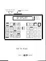
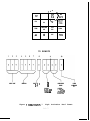
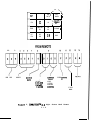
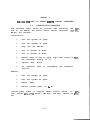
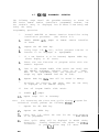
®
Outdoor Warning
ENGINEERING COMPANY INC.
Route 145, Winthrop Road,
Chester, Connecticut 06412
Phone: (800) 63SIREN
Phone: (860) 526-9504
Fax: (860) 526-4784
Internet: www.whelen.com
Sales e-mail: [email protected]
Customer Service e-mail: [email protected]
MDK-864
MICROPROCESSOR
DIAGNOSTIC
KEYBOARD
864 SERIES REMOTE
STATION CONTROLLERS
USER MANUAL
©1988 Whelen Engineering Company Inc.
Page 1
hJEELEN
MM-864,
MICROPROCESSOR
DIAGNOSTIC
KEYBOARD
FOR
WRELEN
864
SERIES
REMOTE
USER
The information
Engineering
Company,
STATION
CONTROLLERS
MANUAL
contained herein
Incorporated.
is
proprietary
to
Whelen
All
rights
reserved.
No part of this manual may be
reproduced,
recorded
or s t o r e d i n a r e t r i e v a l
system,
or
transmitted,
in
any form or by any means, whether electronic,
mechanical, photographical, or otherwise, without prior written
permission
of
Whelen
Engineering
Company,
Incorporated.
All
Rights
Copyright,
Printed
Reserved.
1988
by
Whelen
Engineering
Company,
Incorporated.
12/88.
All
materials
document are subject
and
specifications
contained
to change without notice.
MDK-864.003
WEELEN
ENGINEERING
COMPANY,
INCORPORATED
Route 145 - Winthrop Road
Chester, Connecticut, 0. S. A. 06412
within
this
WHELEN
MDK-864
USER
TABLE
SECTION
1:
2:
Figure
Figure
Figure
Figure
Figure
Figure
Figure
Figure
SECTION
3:
MDK-864
SECTION
4:
OF
CONTENTS
INTRODUCTION
MDK-864
SECTION
MANUAL
Description....................................l.l.l
HDR-864
1
2
3
4
5
6
7
8
SYSTEM
ILLUSTRATIONS
MDK-864 Keyboard . . . . . . . . . . . . . . . . . . . . . . . . . . . . . . 2.1.1
MDK-864 Register Readout: Status Word.........2.1.2
MDK-864 Register Readout: Instant Status......2.1.3
MDK-864 Register Readout: Function Dips.......2.1.4
MDK-864 Register Readout: Instant
Status
Dips.2.1.5
MDK-864 Register Readout: Decoder
Error
Flags.2.1.6
COMM/STATTM, 10 Digit Activation Word Format..2.1.7
COMM/STATTM, 14 Digit Status Word Format......2.1.8
mm-864
Key
DIAGNOSTIC
KEYS
Descriptions . . . . . . . . . . . . . . . . . . . . . . . . . . . . . . . 3.1.1
MDK-864 USE WITH
CONTROLLERS
864
SERIES
REmYlPE
STATION
MDK-864 Connection/De-connection.......................4.1
.l
MDK-864 Programming Operations ....................... ..4.2 .l
MDK-864
Diagnostic
Uses ................................ 4.3.1
SECTION
1.1
MDK-864
The MDK-864, Microprocessor
for
use
when
performing
Whelen's
864
Series
of
controllers.
The
1
DESCRIPTION
Diagnostic Keyboard is
service
and
routing
Microprocessor
based
MDK-864 consists of a keyboard
programming/diagnostic
numeric
with
two
a service tool
maintenance
on
remote
station
separate
keypads:
Located above the two keypads is a 20 character vacuum
fluorescent display, which
will
display
programming
entries
and
864 series system
controller
programming
and
diagnostic
information.
The display also indicates the MDK-864's power
on/off condition and the MDK-864 programming active mode.
The
MDK-864
serves
two
functions
for
the
user:
First, the MDK-864 provides access to all 864 Series Remote
Station
Controllers
memory, allowing the user to change the
v a r i o u s s y s t e m p r o g r a m m i n g , such as a s y s t e m ' s r e m o t e
station
address or to vary the pre-programed timing
parameters for siren/voice activation durations and duty
cycles.
Second,
the
keyboard
permitting access to
controller's
memory
for
and
status
registers.
serves
as
a
diagnostic
monitor,
the remote station's 864 Series
examination
of
existing
programming,
The MDK-864 consists of two parts, the interface cable and
display
keyboard.
A slide switch is located on the rear panel of
the MDK-864 keyboard (next to the 25 pin D connector) to activate
the
keyboard's
programming
active
mode.
1.1.1
Mm-864
Figure
Figure
Figure
Figure
Figure
Figure
Figure
Figure
1
2
3
4
5
6
7
8
SECTION
2
SYSTEM
ILLUSTRATIONS
MDK-864 Keyboard ..*........................... 2.1.1
MDK-864 Register Readout: Status Word.........2.1.2
MDK-864 Register Readout: Instant Status......2.1.3
MDK-864 Register Readout: Function Dips.......2.1.4
MDK-864 Register Readout: Instant
Status
Dips.2.1.5
MDK-864 Register Readout: Decoder
Error
Flags.2.1.6
COMM/STATTM, 10 Digit Activation Word Format..2.1.7
COMM/STATTM, 14 Digit Status Word Format......2.1.8
2.1.0
Program Enable Slide Switch
OFF (( Enable )> ON
25 Pos. D Connector
/
I
DISPLAY
lo/
lol
STA
TEMP
lnl
CLR
Ioi
PROG
NOT TO SCALE
Figure
1,
mu-864
2.1.1
Keyboard
0
POWER ON
a
PROGRAM IND.
i
1
I
I
OEC
DATA
ENC
DATA
SELECT
PROG
AC
OEC
ERR
I
S/N
STATUS WORD
OY NAMIC
AC
7
PWR-UP
O-ON
SYSTEM ARM
O-DISARM
SIREN ON
O-OFF
STORED
AC
STORED
ROTOR
STORED
PARTIAL
STORED
FULL
1 -OFF
6
1 -ARM
5
l - 4O N
3
2
1
0
Figure
2,
MDK-864
Register
2.1.2
Readout:
Statue
Word
-
I
OEC
DATA
RST
I
TEMP
4' -
INSTANT STATUS
7
6
5
BIAS
PART
FULL
Figure
3, MDK-864
AC
FUNCTION
STA
DIP
CLEAR
DEC
ERR
S/N
PRIJG
,
/
i
SELECT ,
OC
DIP
INT
STA
ENC
DATA
/
4
3
Register
2.1.3
Readout:
PROG
2
Instant
1
0
INTRUSION
AC
Status
,
SELECT ,
PROG
STA
FUNCTION
OIP
TEMP i
\
INT
STA
FUNCTION DIPS
?
8
MASTER TMX
ON - ON
OFF - OFF
IMMEDIATE
RESPONSE
ON - ON
OFF - OFF
”
?!
S T A
DIP
CLEAR
S/N
PROG
-GE+
ERR
6
5
INSTANT
RESPONSE
ON - ON
OFF - OFF
AC/BAT
CHECK
ON - ON
OFF - OFF
4
1
3
2
SIREN
30 SEC
OEC F O R M A T
ENABLE
LEO CLR
10. O N
ENABLE - ON
30 SEC - ON
8 - OFF
DISABLE - OFF INFINITE . OFF
Figure 4, WDK-864 Register Readout:
2 . 1 . 4
Function
Dips
1
PASSWORO
ON - ON
OFF - OFF
I
AST
STA
TEMP
INT
STA
OC
/
OEC
DATA
ENC
OATA
/ #-AL
SELECT
PROG
\
STA
DIP
FUNtZ;IOi
t
I
\
OEC
ERR
\
‘CLEAR
I
8
l
.
‘ s / n (
PROG
L
INSTANT STATUS DIPS
6
7
6
TONE
GEN
BIAS
PART
FULL
5
4
3
2
1
INTRUSION
AC
,
Figure
5, MDK-864
Register
Readout:
2.1.5
Inatant
Status
Dips
OEC
DATA
RST
STA
DECODER ERROR FLAG
7
6
Figure
Fl!%:‘oN
-\
/
7
i
INT
STA
5
AC
SELECT ,
PROG
STA
DIP
CLEAR
DC
TEMP
’
’
\
.
c
: S/N
,
@
5
‘t
OEC
EHR
\
ENC
DATA
/
PROG
,
4
4
3
2
1
0
PASSWORD
ERR
IIIGIT
COUNT
ERR
ADDRESS
ERR
AREA CODE
ERR
OIGIT
LENGTH
ERR
6, H D K - 8 6 4 R e g i s t e r
Readout:
2 . 1 . 6
Decoder
Error
Flags
/-
/
I
FIST
.
\
OEC
DA ;A
\
,
/
/
’ ENC
i DATA
STA
DC
L d’
AC
TEMP
FUNCTION
DIP
STA
DIP
CLEAR
INT
STA
IJEC
ERR
S/N
PROG
%iEoccT
TO REMOTE
AREA CODE
7-J
ADDRESS
I
BASE I.D. #
O-F
OO-BASE
Ol-ws-3000
1 o-ws-805
11 -ws-2000
Figure 7 CO?¶H/STATtm.
10
Digit
2.1.7
COMMAND
GROUP
O-SIREN
1 -STATUS
Z-W EATHER
3-CONTROL
Activation
Word
SIREN
COMMAND
O-F
Format
9
12
AREA CODE
,
/
/
\
\
ENC
DATA
OEC i
DATA,
FIST
-1
'
I
STA
OC
AC
\II
/
LSLECL$ROG
I
4
TEMP
FUNCTION
DIP
STA
DIP
CLEAR
INT
STA
OEC
ERR
S/N
PROG
1
3
AOORESS
# D%r
coGE~D
I
00-BASE
_ %-if?
ll-ws-2tluo
Figure
8, COIW/STA~,
O-SIREN
l-STATUS
E-WEATHER
3-CONTROL
SIREN f,OFMANll
STATUS
WORD
14 Digit Status Word Format
2.1.8
SECTION
MDK-864
3.1
Two
16
key
keypads
are
DIAGNOSTIC
KEY
located
3
KEYS
DESCRIPTIONS
on
the
front
panel
of
the
MDK-864.
As indicated in Figure 1 in Section 2, the left keypad offers a
the
right
keypad
selection
of
Diagnostic
and
Programming
Keys;
is a hex keypad: O-9, A, B, C & D, which is used for selecting
programming
options
and
programming
entry.
This Section details the purpose and function of the Diagnostic
and Programming Keys on the MDK-864 Left Keypad as indicated in
Figure 1 in Section 2.
Key
Use/Function
RST
T h e R S T k e y resets
the
864
Series r e m o t e s t a t i o n
microprocessor
controller.
This key is to be depressed
f o l l o w i n g connection of the MDK-864 to the Remote
Station Controller as detailed in Section 4.1.,
or in
the event the keyboard will not clear.
DEC. D A T A
Pressing the DEC.DATA key causes the last data
received by the Remote Station's 864 Series Controller
This may be interpreted according to
to be displayed.
Figure 7 in Section 2.
ENC.
Pressing
the
ENC. D A T A k e y c a s e s t h e l a s t d a t a
transmitted
by the
Remote
Station's
864
Series
Controller to be displayed.
This may be interpreted
according to Figure 8 in Section 2.
Data
STA
Pressing the STA key causes the information stored in
the
Remote
Stations
864
Series
controller's
status
register to be displayed.
This
information
is
updated
The
Status
after
each
remote
station
operation.
Register Display is indentified in Figure 2 in Section
2.
DC
VOLTS
Pressing the DC VOLTS
battery voltage to be
AC
VOLTS
Pressing the AC VOLTS key causes the
AC supply voltage to be displayed.
SEL
PROG
Pressing
function
the
for
key causes
displayed.
the
remote
remote
SEL PROG key permits the
display
or
reprogramming.
3.1.1
station's
station's-
selection
of
a
Key
Use/Function
TEMP
Pressing the TEMP key causes the temperature in
degree's Fahrenheit inside the Remote Station's 864
Controller's
housing
to
be
displayed.
Note:
Systems
m a y optionally be equipped with external ambient
temperature sensors;
pressing the TEMP key for these
systems will
cause a display of the temperature as
indicated by the external sensor.
FUN
DIP
Pressing the FUN DIP key causes a display of the Remote
Station's Controller Function Dip Register, which
indicates the setting of the Function Dip switches on
the
remote
station's
864
Series
Controller.
(See
Figure 4 of Section 2.).
STA
DIP
Pressing the STA DIP key causes a display of the Remote
Station's
Controller
Instant
Status
Dip
Register,
which
indicates
the
s e t t i n g of
the
Instant
Status
Dip
switches on the remote station's 864 Series Controller.
(See Figure 5 of Section 2.).
CLEAR
Pressing this key will set the value of the function
selected
(MDK-864
Function/Programming
Keys) to all
zero's.
INT
STA
Pressing the INT STA key causes the information stored
in the Remote Station's 864 Series controller's Instant
Status
register
to
be
displayed.
This
information
is
reflects the remote station's real t i m e status.
The
Instant Status Register Display is indentfied in Figure
5 in Section 2.
DEC
ERR
Pressing the DEC ERR causes decoder error flags for
data
decoded
by
the
864
Series
Remote
Station
Controller
b e displayed.
(See Figure 6 in Section 2
for the Decoder Error Flag Register.)
S/N
Pressing the S/N key causes
noise ratio received by the
Controller
to
be
displayed.
displayed in dB.
3.1.2
the
864
The
most
recent signal to
Series Remote Station
received S/N value is
Key
Use/Function
PROG
T h e P R O G k e y i s used
in
conjunction
with
numeric
keys O-9, A, B, C & D, to select the function
keypad,
to be programmed.
After pressing the PROG key, the
MDK-864 display will read:
Se1 P r o g .
Programs
available
are:
1.
Wail
2.
Attach
3.
Alert
4.
Public
5.
Air
6.
Hi/Low
7.
Whoop
tone
8.
Five
second
9.
Siren
0.
Secur-a-key
A.
Substitute
B.
tone
duration.
tone
tone
duration.
duration.
Address
Horn
tone
tone
max
duration.
duration.
duration.
duration.
wail
tone
duration.
address.
Transmitter
number.
number.
turn
on
delay.
Note :
In order to write new program data to the 864
Series Remote Station Controller, the program switch on
the rear panel of the MDK-864 Keyboard must be turned
to the Program Active Position.
The program switch is
a two position slide switch.
The
Program
Active
position is position nearest the 25 pin - D connector
on the rear panel of the MDK-864 Keyboard.
When the
MDK-864 Keyboard is in the program Active mode, and LED
in the lower right hand corner of the MDK-864 Keyboard
will be lighted.
3.1.3
4
SECTION
MIX-864
USE
WITH
4.1
864
SERIES
REMYl'E
STATION
CONTROLLERS
CONNECTION/DE-CONNECTION
The following steps should be utilized when
864 to any Whelen 864 Series Remote Station
MS-864 and RTU-864):
connecting
Controller
the MDK(ESC-864,
Installation
1.
Turn
off
system*
AC
power.
2.
Turn
off
system*
DC
power.
3.
Plug
into
4.
Turn
on
system*
DC
power.
5.
Turn
on
system*
AC
power.
6.
Observe power on LED in upper right
864 Controller Display is on.
7.
Depress
8.
For operation
sections.
the
"RST"
ESC-864.
hand
corner
of
MDK-
button.
refer
to
programming
and
diagnostic
Removal
1.
Turn
off
system*
AC
power.
2.
Turn
off
system*
DC
power.
3.
Remove
cable.
4.
Restore
system*
power,
DC
&
AC.
*System power refers to complete remote
2000
Series, WE%-2700
Series, WPS-3000,
864.
4.1.1
station device, ie:
WPS-4000, MS-864 or
WPSRTU-
4.2
MDK-864
PROGRAMMING
OPERATION
The following steps detail the procedure necessary to access an
864 Series Remote Station Controller's programming routines, how
the routine's entry is displayed, how to enter a new entry and
verify the entry.
Programming
Note:
Operation:
1.
Install MDK-864 to Remote Station Controller using
installation procedure.
(See Section 4.1).
2.
Enable EEPROM
PC board.
3.
Depress
4.
Using keys l-9, & A-C, select program
function to be displayed or reprogrammed.
5.
If a new function is to be inserted, depress CLEAR key.
(Clears display to all zeros).
6.
Enter the new function or program value with the
numeric keyboard.
7.
Turn on the Program Enable slide switch and verify that
the MDK-864 programing indicator light is on.
(NOTE:
When in the programming mode, the Controller will not
accept any input commands from the RF link).
8.
Depress PROG key (new
9.
Re-select the function, and verify that
is displayed on the MDK-864 display.
10.
Turn
11.
Disable
12.
Repeat
the
off
(E2)
SEL
jumper
PROG
Program
jumper.
steps
3-10
Remote
Station
Controller
key.
routine
or
data will be stored in memory).
Enable
E2
on
as
slide
the
new
entry
switch.
necessary.
For accessing the siren tone cyclic timinq program for
mechanical sirens, perform the following steps1.
Depress
the
SEL
PROG
key.
2.
Depress
the
ENTER
3.
Using keys l-8, select
to be programmed.
4.
Siren cyclic
durations.
increments.
key.
the
tone
for
the
cyc lit t iming
timing will be displayed in ON-OFF
Timing durations are shown in
To program, follow step 5-11 above.
4.2.1
timing
1OOms
Programming
Program
Selections,
Selection
Display
of
Program
Function
Display
l-8
Siren
Tone
Duration
9
Siren
Address
A
Substitute
Number
B.
Transmitter
Turn
Minutes
-
Seconds
Activation Word, as
displayed in Figure
7, Section 2.
Enter
A
'* C "
i n
remote
station
address
digits
according to Figure
7, Section 2.
on
Delay
Turn
on
delay time
is e x p r e s s e d
in
seconds - tenths of
seconds.
PROG,
ENTER,
1-5
Mechanical
Timing
Siren
Cyclic
Cyclic
Timing
is
displayed in on/off
time
durations.
Durations
are
in
1OOms
increments.
4.2.2
4-3
1.
DEC
DATA
AREA
DIAGNOSTIC
(see
Figure
- three
CODE
ID date.
Section
digit
A D D R E S S - four
station.
BASE
7,
number
digit
identifies
DISPLAYS
2.
GROUP
COMMAND
- 1-16
(O-F
(see
Figure
ENC
DATA
DIGITS
3.
the
11
2).
DIGITS
13
STATUS
WORD
digit
&
12
type
that
customer.
identifies
station
that
each
that
data
is
each
sent
being
the
sent
(binary).
hex).
8,
Section
(see
hex
Dynamic
- If
System
Arm -
On sound.
word
analog
voltage
Figure
2,
code,
2).
four
in
hex
in
hex
Section
bit
code
(see
Figure
code O-255.
2)
binary
per
digit.
(-j= "OFF" /"NO"
AC-AC
Pwr-Up
status
-
C 14 -
1~ "ON"/"yES"
Siren
O-4
base
to
l-10 - same as DEC DATA.
DIGITS
Two
-
unique
number
EQUIPMENT TAG - equipment
to
(binary).
COMMAND
2)
power
AC
input
System
System
on/off
is
on
armed
form
last
system
for
will
instant
enabled/disabled
4.3.1
activation.
be
powered
status
to
up.
response.
make
audible
3.
4.
STATUS
WORD
(see
Stored
AC -
AC
Rotor
- rotor
power
2
Section
on/off
operation
more
Full
operated
- All
INSTANT
1~
speakers
STATUS
time
“ON”
o=
Figure
not
stored.
Gen
Part
- one
or
Full
-
speakers
AC -
form
3,
21,
continued
previous
activation.
activation.
operated
last
Section
form
last
activation.
2).
"OFF"
Tone
Bias -
all
Intrusion
last
speakers
(see
data
from
from
P a r t i a l - one or
activation.
Real
5.
Figure
tone
more
- cabinet
generator
speakers
on/off.
on/off.
on.
door(s)
open.
on/off.
FUNCTION
DIPS
-
(see
Figure
Displays the
the
ESC-864.
setting
Master
transmitter
TMX -
Immediate
Instant
of
4,
the
Section
2).
function
dip
switches
in
enabled/disabled.
Response
enabled/disabled.
Allows the ESC864 to return status data without a request,
if it was activated as a individual unit.
Response - enabled/disabled.
Allows the ESC864 to return status data without a request,
if it sees a change of state on designated
bits in the status register.
4.3.2
5.
FUNCTION
DIPS
-
(see
Figure
4,
Section
2),
continued.
If enabled will
AC/BATT Check - enabled/disabled.
transmit loss of AC power, when battery
voltage drops below 19 vdc.
Siren
If enabled allows base
disable audible sound.
Sound - enabled/disabled.
station to enable or
If on maintenance led's on
30 SEC LED CLR - on/off.
ESC-864 will go out after 30 sec. of
operation.
DEC
FORMAT
PASSWORD
6.
INSTANT
See
- on/off.
On ESC-864
will accept 10 digit
format. Off it will accept 8 digit format.
- enabled/disabled.
STATUS
instant
DIPS
status
(see
Figure
word
for
5,
bit
Section
2).
descriptions.
Enabled/Disabled.
If bit is enabled, when ESC-864 sees that bit change
state it will transmit the instant status word to base
station.
6.
DECODER
Used
l=
ERROR
to
(see
trouble-shoot
"PASS"
PASSWORD
FLAG
2=
Figure
6,
activation
Section 2).
failures.
"ERROR"
- correct/incorrect.
DIGIT COUNT - not 10 or 8.
ADDRESS
- correct/incorrect.
AREA CODE - correct/incorrect.
DIGIT
LENGTH - word transmitted
correct/incorrect.
4.3.3
to
ESC-864
window
time