1
% #
%$ "'
$$ '!$ "' %%! ( '!$ $" &#"
Copyright 1993 by Siemens Industrial Automation, Inc.
All Rights Reserved — Printed in USA
Reproduction, transmission or use of this document or
contents is not permitted without express consent of
Siemens Industrial Automation, Inc. All rights, including rights
created by patent grant or registration of a utility model or
design, are reserved.
Since Siemens Industrial Automation, Inc. does not possess
full access to data concerning all of the uses and applications
of customer’s products, we do not assume responsibility either
for customer product design or for any infringements of patents
or rights of others which may result from our assistance.
01/21/92
Technical data is subject to change.
We check the contents of every manual for accuracy at the
time it is approved for printing; however, there may be
undetected errors. Any errors found will be corrected in
subsequent editions. Any suggestions for improvement are
welcomed.
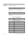
MANUAL PUBLICATION HISTORY
SIMATIC TI575 Task Code User Manual
Order Manual Number: PPX:575–8104–1
Refer to this history in all correspondence and/or discussion about this manual.
Event
Date
Description
Original Issue
04/93
Original Issue (2801374–0001)
LIST OF EFFECTIVE PAGES
Pages
Cover/Copyright
History/Effective Pages
iii — vii
1-1 — 1-12
2-1 — 2-21
3-1 — 3-9
Registration
Description
Original Edition
Original Edition
Original Edition
Original Edition
Original Edition
Original Edition
Original Edition
Pages
Description
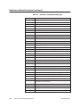
Contents
Preface
Chapter 1
Task Code Parameter Descriptions
Word Area Address Descriptors . . . . . . . . . . . . . . . . . . . . . . . . . . . . . . . . . . . . . . . . . . . . . . . . . . . . . . . . .
1-2
Word Codes . . . . . . . . . . . . . . . . . . . . . . . . . . . . . . . . . . . . . . . . . . . . . . . . . . . . . . . . . . . . . . . . . . . .
Category I Word Code Description . . . . . . . . . . . . . . . . . . . . . . . . . . . . . . . . . . . . . . . . . . . . . .
V/K Encoding . . . . . . . . . . . . . . . . . . . . . . . . . . . . . . . . . . . . . . . . . . . . . . . . . . . . . . . . . . . . . . . . . . .
G Encoding . . . . . . . . . . . . . . . . . . . . . . . . . . . . . . . . . . . . . . . . . . . . . . . . . . . . . . . . . . . . . . . . . . . .
DCP Encoding . . . . . . . . . . . . . . . . . . . . . . . . . . . . . . . . . . . . . . . . . . . . . . . . . . . . . . . . . . . . . . . . . .
WX/WY/DCC/STW Encoding . . . . . . . . . . . . . . . . . . . . . . . . . . . . . . . . . . . . . . . . . . . . . . . . . . . . .
TCP/TCC Encoding . . . . . . . . . . . . . . . . . . . . . . . . . . . . . . . . . . . . . . . . . . . . . . . . . . . . . . . . . . . . .
DSP/DSC Encoding . . . . . . . . . . . . . . . . . . . . . . . . . . . . . . . . . . . . . . . . . . . . . . . . . . . . . . . . . . . . .
Category 2 Word Code Description . . . . . . . . . . . . . . . . . . . . . . . . . . . . . . . . . . . . . . . . . . . . . .
Category 3 Word Code Description . . . . . . . . . . . . . . . . . . . . . . . . . . . . . . . . . . . . . . . . . . . . . .
Category 4 VMEbus Word Code Description . . . . . . . . . . . . . . . . . . . . . . . . . . . . . . . . . . . . .
1-2
1-3
1-5
1-5
1-5
1-5
1-6
1-6
1-7
1-9
1-11
Port, Module, and Board Address Descriptors . . . . . . . . . . . . . . . . . . . . . . . . . . . . . . . . . . . . . . . . . . . .
1-12
Port Descriptors . . . . . . . . . . . . . . . . . . . . . . . . . . . . . . . . . . . . . . . . . . . . . . . . . . . . . . . . . . . . . . . . .
1-12
Chapter 2
2.1
Task Code Definitions
Task Code Definition . . . . . . . . . . . . . . . . . . . . . . . . . . . . . . . . . . . . . . . . . . . . . . . . . . . . . . . . . . . .
2-2
TC01 Read Word Memory Random . . . . . . . . . . . . . . . . . . . . . . . . . . . . . . . . . . . . . . . . . . . . . .
TC02 Write Word Memory Area Random . . . . . . . . . . . . . . . . . . . . . . . . . . . . . . . . . . . . . . . . .
TC30 Read Operational Status . . . . . . . . . . . . . . . . . . . . . . . . . . . . . . . . . . . . . . . . . . . . . . . . . . .
TC32 Program to Run Mode . . . . . . . . . . . . . . . . . . . . . . . . . . . . . . . . . . . . . . . . . . . . . . . . . . . . .
TC33 Go to Program Mode . . . . . . . . . . . . . . . . . . . . . . . . . . . . . . . . . . . . . . . . . . . . . . . . . . . . . .
TC34 Execute Power-up . . . . . . . . . . . . . . . . . . . . . . . . . . . . . . . . . . . . . . . . . . . . . . . . . . . . . . . . .
TC35 Execute Complete (Warm) Start . . . . . . . . . . . . . . . . . . . . . . . . . . . . . . . . . . . . . . . . . . . .
TC36 Execute Partial (Hot) Start . . . . . . . . . . . . . . . . . . . . . . . . . . . . . . . . . . . . . . . . . . . . . . . . . .
TC50 Read User Word Area Block . . . . . . . . . . . . . . . . . . . . . . . . . . . . . . . . . . . . . . . . . . . . . . . .
TC51 Write User Word Area Starting at Address . . . . . . . . . . . . . . . . . . . . . . . . . . . . . . . . . . . .
TC58 Set Controller Time of Day Clock . . . . . . . . . . . . . . . . . . . . . . . . . . . . . . . . . . . . . . . . . . .
TC59 Write Discrete I/O Status via Data Element Type . . . . . . . . . . . . . . . . . . . . . . . . . . . . .
TC5A Write Block . . . . . . . . . . . . . . . . . . . . . . . . . . . . . . . . . . . . . . . . . . . . . . . . . . . . . . . . . . . . . . . .
TC6B Read Discrete I/O Status Using Data Element Type . . . . . . . . . . . . . . . . . . . . . . . . . .
TC71 Read Controller Time of Day Clock . . . . . . . . . . . . . . . . . . . . . . . . . . . . . . . . . . . . . . . . .
TC7D Read SF/Loop Processor Mode . . . . . . . . . . . . . . . . . . . . . . . . . . . . . . . . . . . . . . . . . . . . .
TC7E Read Random . . . . . . . . . . . . . . . . . . . . . . . . . . . . . . . . . . . . . . . . . . . . . . . . . . . . . . . . . . . .
TC7F Read Block . . . . . . . . . . . . . . . . . . . . . . . . . . . . . . . . . . . . . . . . . . . . . . . . . . . . . . . . . . . . . . . .
TC88 Select Number of SF Module Task Codes Per Scan . . . . . . . . . . . . . . . . . . . . . . . . . . .
TC89 Read Number of SF Module Task Codes Per Scan . . . . . . . . . . . . . . . . . . . . . . . . . . .
TC8D Subcommand 00 – Read I/O Base Enable/Disable Status . . . . . . . . . . . . . . . . . . . .
TC8D Subcommand 01 – Write Mask to Controller . . . . . . . . . . . . . . . . . . . . . . . . . . . . . . . .
TC8D Subcommand 02 – Read I/O Base Configuration . . . . . . . . . . . . . . . . . . . . . . . . . . .
TC93 Assign/Deassign Port . . . . . . . . . . . . . . . . . . . . . . . . . . . . . . . . . . . . . . . . . . . . . . . . . . . . . . .
TC93 Subcommand 00 – Read Port Assignments . . . . . . . . . . . . . . . . . . . . . . . . . . . . . . . . . .
2-2
2-2
2-2
2-7
2-7
2-7
2-8
2-8
2-9
2-9
2-10
2-11
2-11
2-12
2-12
2-13
2-13
2-14
2-14
2-15
2-15
2-16
2-16
2-16
2-17
Contents
iii
TC93 Subcommand 01 – Assign Port to Application . . . . . . . . . . . . . . . . . . . . . . . . . . . . . . .
TC93 Subcommand 02 – Deassign Port . . . . . . . . . . . . . . . . . . . . . . . . . . . . . . . . . . . . . . . . . . .
TC94 Configure Port . . . . . . . . . . . . . . . . . . . . . . . . . . . . . . . . . . . . . . . . . . . . . . . . . . . . . . . . . . . . .
TC94 Subcommand 00 – Read Port Configuration . . . . . . . . . . . . . . . . . . . . . . . . . . . . . . . .
TC94 Subcommand 01 – Set Port Configuration . . . . . . . . . . . . . . . . . . . . . . . . . . . . . . . . . . .
TC99 Write VME Memory Area Block/Random . . . . . . . . . . . . . . . . . . . . . . . . . . . . . . . . . . . .
TC9A Read VME Memory Area Block/Random . . . . . . . . . . . . . . . . . . . . . . . . . . . . . . . . . . .
Chapter 3
2-17
2-17
2-18
2-18
2-19
2-20
2-21
Communication Protocols
3.1
Overview . . . . . . . . . . . . . . . . . . . . . . . . . . . . . . . . . . . . . . . . . . . . . . . . . . . . . . . . . . . . . . . . . . . . . . .
3-2
3.2
Non-Intelligent Terminal Protocol (NITP) . . . . . . . . . . . . . . . . . . . . . . . . . . . . . . . . . . . . . . . . . .
3-3
NITP Format . . . . . . . . . . . . . . . . . . . . . . . . . . . . . . . . . . . . . . . . . . . . . . . . . . . . . . . . . . . . . . . . . . . .
NITP Character Set . . . . . . . . . . . . . . . . . . . . . . . . . . . . . . . . . . . . . . . . . . . . . . . . . . . . . . . . . . . . . .
Message Delimiters . . . . . . . . . . . . . . . . . . . . . . . . . . . . . . . . . . . . . . . . . . . . . . . . . . . . . . . . . . . . .
Character Count . . . . . . . . . . . . . . . . . . . . . . . . . . . . . . . . . . . . . . . . . . . . . . . . . . . . . . . . . . . . . . .
Message Body . . . . . . . . . . . . . . . . . . . . . . . . . . . . . . . . . . . . . . . . . . . . . . . . . . . . . . . . . . . . . . . . . .
Error-checking Code . . . . . . . . . . . . . . . . . . . . . . . . . . . . . . . . . . . . . . . . . . . . . . . . . . . . . . . . . . . .
3-3
3-3
3-4
3-4
3-4
3-4
Transparent Byte Protocol . . . . . . . . . . . . . . . . . . . . . . . . . . . . . . . . . . . . . . . . . . . . . . . . . . . . . . .
3-6
UART Initialization Requirements . . . . . . . . . . . . . . . . . . . . . . . . . . . . . . . . . . . . . . . . . . . . . . . . .
Message Format . . . . . . . . . . . . . . . . . . . . . . . . . . . . . . . . . . . . . . . . . . . . . . . . . . . . . . . . . . . . . . . .
Initiator . . . . . . . . . . . . . . . . . . . . . . . . . . . . . . . . . . . . . . . . . . . . . . . . . . . . . . . . . . . . . . . . . . . . . . . . .
Responder . . . . . . . . . . . . . . . . . . . . . . . . . . . . . . . . . . . . . . . . . . . . . . . . . . . . . . . . . . . . . . . . . . . . .
RL Byte . . . . . . . . . . . . . . . . . . . . . . . . . . . . . . . . . . . . . . . . . . . . . . . . . . . . . . . . . . . . . . . . . . . . . . . . .
LL Byte . . . . . . . . . . . . . . . . . . . . . . . . . . . . . . . . . . . . . . . . . . . . . . . . . . . . . . . . . . . . . . . . . . . . . . . . .
TC Byte . . . . . . . . . . . . . . . . . . . . . . . . . . . . . . . . . . . . . . . . . . . . . . . . . . . . . . . . . . . . . . . . . . . . . . . . .
Message Timeouts . . . . . . . . . . . . . . . . . . . . . . . . . . . . . . . . . . . . . . . . . . . . . . . . . . . . . . . . . . . . . .
Message Turn Around Time . . . . . . . . . . . . . . . . . . . . . . . . . . . . . . . . . . . . . . . . . . . . . . . . . . . . . .
Minimum Time Between Requests . . . . . . . . . . . . . . . . . . . . . . . . . . . . . . . . . . . . . . . . . . . . . . . .
Application Note for Parity Checking NITP Message . . . . . . . . . . . . . . . . . . . . . . . . . . . . . . .
3-6
3-6
3-6
3-6
3-6
3-7
3-7
3-8
3-8
3-8
3-9
3.3
iv
Contents
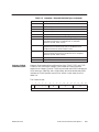
List of Figures
2-1
2-2
2-3
2-4
Status Word 1
Status Word 2
Status Word 3
Status Word 9
.....................................................................
.....................................................................
.....................................................................
.....................................................................
2-2
2-3
2-4
2-5
3-1 Command and Response Messages . . . . . . . . . . . . . . . . . . . . . . . . . . . . . . . . . . . . . . . . . . . . . . .
3-3
Contents
v
List of Tables
1-1
1-2
1-3
1-4
1-5
Word Code Categories . . . . . . . . . . . . . . . . . . . . . . . . . . . . . . . . . . . . . . . . . . . . . . . . . . . . . . . . . . . .
Memory Type Page Sizes . . . . . . . . . . . . . . . . . . . . . . . . . . . . . . . . . . . . . . . . . . . . . . . . . . . . . . . . . .
f – Variable Data Format . . . . . . . . . . . . . . . . . . . . . . . . . . . . . . . . . . . . . . . . . . . . . . . . . . . . . . . . . . .
wwww – Variable Data . . . . . . . . . . . . . . . . . . . . . . . . . . . . . . . . . . . . . . . . . . . . . . . . . . . . . . . . . . . .
wwwwww – Extended Variable Type . . . . . . . . . . . . . . . . . . . . . . . . . . . . . . . . . . . . . . . . . . . . . . .
1-3
1-4
1-7
1-7
1-8
2-1 Controller Type . . . . . . . . . . . . . . . . . . . . . . . . . . . . . . . . . . . . . . . . . . . . . . . . . . . . . . . . . . . . . . . . . . . .
2-4
3-1
3-2
3-3
3-4
3-3
3-5
3-8
3-9
vi
Standard ASCII Codes . . . . . . . . . . . . . . . . . . . . . . . . . . . . . . . . . . . . . . . . . . . . . . . . . . . . . . . . . . . . .
NITP Message Structure . . . . . . . . . . . . . . . . . . . . . . . . . . . . . . . . . . . . . . . . . . . . . . . . . . . . . . . . . . . .
Maximum Length Message Values . . . . . . . . . . . . . . . . . . . . . . . . . . . . . . . . . . . . . . . . . . . . . . . . .
ASCII Character Values for NITP . . . . . . . . . . . . . . . . . . . . . . . . . . . . . . . . . . . . . . . . . . . . . . . . . . . .
Contents
Preface
Task Codes are the command/response messages sent to Series 500 and
Series 505controllers. These codes are sent
•
through the RS-232 and RS-422 communication ports.
•
through Special Functions modules such as the NIM.
•
across the VMEbus using the interboard messaging service in the
SIMATIC TI575. Refer to SIMATIC TI575 Interboard
Communication Manual (PPX:575–8103).
Task Codes are used to initiate modes of operation, and to Read/Write
controller data.
This section defines the symbols used to represent the various fields of the
task codes. The definitions given in this section apply only when the task
code description does not define the symbols used.
NOTE: Symbols defined with the task code descriptions take precedence for
that task code.
The following conventions are used throughout this manual:
TI575 Task Code
The use of upper case or lower case symbols is significant.
[ ] (brackets) indicate optional parameters.
... (a series of periods) means a repetition of zero or more times.
Preface
vii
Chapter 1
Task Code Parameter Descriptions
1.1
1.2
Word Area Address Descriptors . . . . . . . . . . . . . . . . . . . . . . . . . . . . . . . . . . . . . . . . . . . . . . . . . .
1-2
Word Codes . . . . . . . . . . . . . . . . . . . . . . . . . . . . . . . . . . . . . . . . . . . . . . . . . . . . . . . . . . . . . . . . . . . .
Category I Word Code Description . . . . . . . . . . . . . . . . . . . . . . . . . . . . . . . . . . . . . . . . . . . . . .
V/K Encoding . . . . . . . . . . . . . . . . . . . . . . . . . . . . . . . . . . . . . . . . . . . . . . . . . . . . . . . . . . . . . . . . . . .
G Encoding . . . . . . . . . . . . . . . . . . . . . . . . . . . . . . . . . . . . . . . . . . . . . . . . . . . . . . . . . . . . . . . . . . . .
DCP Encoding . . . . . . . . . . . . . . . . . . . . . . . . . . . . . . . . . . . . . . . . . . . . . . . . . . . . . . . . . . . . . . . . . .
WX/WY/DCC/STW Encoding . . . . . . . . . . . . . . . . . . . . . . . . . . . . . . . . . . . . . . . . . . . . . . . . . . . . .
TCP/TCC Encoding . . . . . . . . . . . . . . . . . . . . . . . . . . . . . . . . . . . . . . . . . . . . . . . . . . . . . . . . . . . . .
DSP/DSC Encoding . . . . . . . . . . . . . . . . . . . . . . . . . . . . . . . . . . . . . . . . . . . . . . . . . . . . . . . . . . . . .
Category 2 Word Code Description . . . . . . . . . . . . . . . . . . . . . . . . . . . . . . . . . . . . . . . . . . . . . .
Category 3 Word Code Description . . . . . . . . . . . . . . . . . . . . . . . . . . . . . . . . . . . . . . . . . . . . . .
Category 4 VMEbus Word Code Description . . . . . . . . . . . . . . . . . . . . . . . . . . . . . . . . . . . . .
1-2
1-3
1-5
1-5
1-5
1-5
1-6
1-6
1-7
1-9
1-11
Port, Module, and Board Address Descriptors . . . . . . . . . . . . . . . . . . . . . . . . . . . . . . . . . . . . .
1-12
Port Descriptors . . . . . . . . . . . . . . . . . . . . . . . . . . . . . . . . . . . . . . . . . . . . . . . . . . . . . . . . . . . . . . . . .
1-12
TI575 Task Code
Task Code Parameter Descriptions
1-1
Word Area Address Descriptors
Word Codes
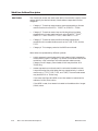
Task Codes that access user word areas within the controller require a word
code to identify the desired value(s). Word codes are separated into four
categories:
•
Category 1. Those that access memory types supported by a discrete
machine such as the SIMATIC TI530C or SIMATIC TI560.
•
Category 2. Those that access Loop and Analog Alarm Variables
supported only in batch machines such as the SIMATIC TI565,
SIMATIC TI545 SIMATIC TI555, and SIMATIC TI575.
•
Category 3. Those that access timeline variables supported by
controllers with tunable timelines such as the TI545, TI555, and the
TI575.
•
Category 4. This category contains the VMEbus word code.
Word codes are represented by different symbols:
•
AAAA represents a word code used in task codes initially intended to
access memory types in Category 1 by earlier Series 500 and Series 505
controllers. Later controllers also use these task codes to access
Category 2 and Category 3 word codes. AAAA may be either 16 or
32-bits long.
•
wwww represents a word code used in task codes intended to access
Loop and Analog Alarm Variables that are supported only in a batch
machine (e.g., TI575, TI565, TI555, and TI545). The word code wwww
may be either 16- or 32-bits long:
If the most significant bit (MSB) is set, then wwww is treated as the
address of a real (32-bit) value.
If the MSB is reset, then wwww is treated as the address of an integer
(16-bit) value.
1-2
Task Code Parameter Descriptions
TI575 Task Code
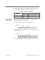
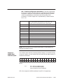
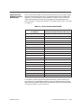
The correspondence between the categories and word code representation
for the task codes are described in this chapter. See Table 1-1.
Table 1-1 Word Code Categories
Controller
Task Code
Category I Word
Code Description
Categories
Representation
01-02, 50-51
1,2,3,4
AAAA or wwww
5A, 7E, 7F
1,2,3,4
wwww
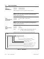
Category 1 user words within the controller are arranged in pages with
page sizes dependent on the type of memory.
The first page (Page 0) is accessed by a single word format.
MSB
bits –>
1
0
2–5
6–16
Word Code
OFFSET
To access successive pages, Word Code F is used as the expansion code and
the format becomes:
MSB
2–5
6
0
1111
0
0
Word Code
bits –>
1
7–16
PAGE
OFFSET
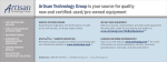
Word code and page sizes for each memory type are defined in Table 1-2.
TI575 Task Code
Task Code Parameter Descriptions
1-3
Word Area Address Descriptors (continued)
Page and Offset. The PAGE and OFFSET fields identify the specific data
element of the memory type specified by the word code.
Table 1-2 Memory Type Page Sizes
Word
Code
Word Code Definition
Page Size
First
Location
0000
Variable Memory (V)
1024
0
0001
Constant Memory (K)
1024
0
0010
Drum Count Preset Memory (DCP)
480
HEX 10
0011
Drum Current Count Memory (DCC)
1024
1
0100
System Status Words Memory (STW)
1024
1
0101
Global Memory (G)
1024
0
0110
Reserved
–
–
0111
Reserved (VMEbus Memory)
–
–
1000
Timer/Counter Preset (TCP) Memory
Timer/Counter Current (TCC) Memory
128
1
1001
Reserved
–
–
1010
Drum Step Preset (DSP) Memory
Drum Step Current (DSC) Memory
30
1
1011
Word Code Expansion with Expanded Offset
1100
Word Input Memory (WX)
1024
1
1101
Word Code Expansion
1110
Word Output Memory (WY)
1024
1
1111
Offset Expansion
The encoding of the PAGE and OFFSET fields of the word address is
dependent upon the value of the WORD CODE field. Equations using the
following operations are given below for each memory type.
1-4
•
a .DIV. b = integer—divide of a by b
•
a .MUL. b = integer—multiply of a by b
•
a .MOD. b = remainder of a .DIV. b
Task Code Parameter Descriptions
TI575 Task Code
V/K Encoding
For V and K memory, the PAGE/OFFSET fields are determined by the
following equations:
PAGE = (N-1).DIV.1024 OFFSET = (N-1).MOD.1024
(Where N is the data element number, e. g. 4073 in V4073.)
Given PAGE and OFFSET, N is determined by:
N = (PAGE.MUL.1024)+1+OFFSET
G Encoding
For G memory, the data element number is determined by:
N = Application * 32768 + Application Offset
Application number for A = 1, B = 2, etc. (0 means current application)
Application Offset ranges from 1 to 32768.
PAGE and OFFSET are then determined as are V and K above.
DCP Encoding
For DCP memory the PAGE/OFFSET fields are determined by the following
equations:
PAGE = (N-1).DIV.30 OFFSET = (((N-1).MOD.30)+1).MUL.16+(S-1)
Where N is the drum number and S is the drum step number.
Given PAGE and OFFSET, N is determined by:
N = (PAGE.MUL.30)+(OFFSET.DIV.16)
WX/WY/DCC/STW
Encoding
For DCC, STW, WX, and WY memory, the PAGE and OFFSET fields are
determined by the following equations:
PAGE = (N-1).DIV.1024
OFFSET = ((N-1).MOD.1024) + 1
(Where N is the data element number, e. g., 53 in WX53.)
Given PAGE and OFFSET, N is determined by the following:
N = (PAGE.MUL.1024)+OFFSET
TI575 Task Code
Task Code Parameter Descriptions
1-5
Word Area Address Descriptors (continued)
TCP/TCC Encoding
The following equations specify the PAGE and OFFSET fields for word
addresses referencing TCP/TCC memory.
NOTE: TCP and TCC memory share a single word code. Because of this, the
encoding of the OFFSET field is used to distinguish between these word
types.
PAGE = (N-1).DIV.128
OFFSET = (N-1).MOD.128 + Z
Where N is the Timer/Counter number and Z is 1 (TCP memory) or 129
(TCC memory).
Given PAGE and OFFSET, N is determined by the following:
N = (PAGE.MUL.128)+((OFFSET-1).MOD.128)+1
DSP/DSC Encoding
The following equations specify the PAGE and OFFSET fields for word
addresses referencing DSP/DSC memory.
NOTE: DSP and DSC memory share a single word code. Because of this, the
encoding of the OFFSET field is used to distinguish between these word
types.
PAGE = (N-1).DIV.30 OFFSET = ((N-1).MOD.30) + Z
Where N is the drum number and Z is 1 (DSP memory) or 31 (DSC
memory).
Given PAGE and OFFSET, N is determined by the following:
N = (PAGE.MUL.30)+((OFFSET-1).MOD.30)+1
1-6
Task Code Parameter Descriptions
TI575 Task Code
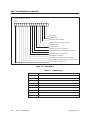
Category 2 Word
Code Description
Category 2 word codes are distinguished by bits 2 through 6, all set to 1. To
access loop and analog alarm data, use:
1
2
3
4
5
6
7
8
9
10
11
12
13
14
15
16
f
1
1
1
1
1
w
w
w
w
n
n
n
n
n
n
Use the single word format to access types defined by word codes 0–E in bits
7–10. Use word code F in bits 7–10 to extend the addressing past 64
variables of a given type, or to reach additional types. The double word
format is
1
2
3
4
5
6
7
8
9
10
11
12
13
14
15
16
f
1
1
1
1
1
1
1
1
1
w
w
w
w
w
w
n
n
n
n
n
n
n
n
n
n
n
n
n
n
n
n
The fields in the category 2 word code follow and are shown in Table 1-3
through Table 1-5.
•
‘nn...n’ is the variable number; ‘1’ is the first variable
Table 1-3 f – Variable Data Format
0
Integer
1
Real
Table 1-4 wwww – Variable Data
TI575 Task Code
0000
Reserved
0001 = LPV
Loop Process Variable
0010 = LSP
Loop Setpoint
0011 = LMN
Loop Output
0100 = LMX
Loop Bias
0101 = LERR
Loop Error
0110 = LKC
Loop Gain
0111 = LTD
Loop Rate
1000 = LTI
Loop Reset
1001 = LVF
Loop V-flags
1010 = LRSF
RAMP/SOAK flags
1011 = APV
Analog Alarm Process Variable
1100 = ASP
Analog Alarm Setpoint
1101 = AVF
Analog Alarm flags
1110
Reserved
1111
Expansion code (see wwwwww )
Task Code Parameter Descriptions
1-7
Word Area Address Descriptors (continued)
Table 1-5 wwwwww – Extended Variable Type
1-8
00xxxx
xxxx is the same as wwww above
010000
Reserved
010001 = LPVL
Loop Process Variable Low Limit
010010 = LPVH
Loop Process Variable High Limit
010011 = APVL
Analog Alarm Process Variable Low Limit
010100 = APVH
Analog Alarm Process Variable High Limit
010101 = LTS
Loop Sample Rate (seconds)
010110 = ATS
Analog Alarm Sample Rate (seconds)
010111 = LHA
Loop High Alarm Limit
011000 = LLA
Loop Low Alarm Limit
011001 = LODA
Loop Orange Deviation Alarm Limit
011010 = LYDA
Loop Yellow Deviation Alarm Limit
011011 = LSPL
Loop Setpoint Low Limit
011100 = LSPH
Loop Setpoint High Limit
011101 = LCFH
Most-significant word of Loop C-flags
011110 = LCFL
Least-significant word of Loop C-flags
011111 = LHHA
Loop High-High Alarm Limit
100000 = LLLA
Loop Low-Low Alarm Limit
100001 = LRCA
Loop Rate-of-Change Alarm Limit (engineering units / minute)
100010 = LADB
Loop Alarm Deadband
100011 = AHA
Analog Alarm High Alarm Limit
100100 = ALA
Analog Alarm Low Alarm Limit
100101 = AODA
Analog Alarm Orange Deviation Alarm Limit
100110 = AYDA
Analog Alarm Yellow Deviation Alarm Limit
100111 = ASPL
Analog Alarm Setpoint Low Limit
101000 = ASPH
Analog Alarm Setpoint High Limit
101001 = ACFH
Most-significant word of Analog Alarm C-flags
101010 = ACFL
Least-significant word of Analog Alarm C-flags
101011 = AHHA
Analog Alarm High-High Alarm Limit
101100 = ALLA
Analog Alarm Low-Low Alarm Limit
101101 = ARCA
Analog Alarm Rate-of-Change Alarm Limit
(engineering units/minute)
101110 = AADB
Analog Alarm Alarm Deadband
101111 = AERR
Analog Alarm Error
110000
Reserved
110001 = LKD
Loop Derivative Gain-limiting coefficient
Task Code Parameter Descriptions
TI575 Task Code
Table 1-5 wwwwww – Extended Variable Type (continued)
Category 3 Word
Code Description
110010 = LRSN
Loop RAMP/SOAK Step Number
110011
Reserved
110100 = X
Discrete input, accessed as a word
110101 = Y
Discrete output, accessed as a word
110110 = C
Control relay, accessed as a word
110111 = LACK
Loop Alarm / Alarm Acknowledge flags
111000 = AACK
Analog-alarm Alarm / Alarm Acknowledge flags
111001 = LPET
Loop Peak Elapsed Time Value - Represents the elapsed time
from when the process is scheduled until it completes
execution (TI545, TI555, TI575)
111010 = APET
Analog Alarm Peak Elapsed Time Value - Represents the
elapsed time from when the process is scheduled until it
completes execution (TI545, TI555, TI575)
111011 = PPET
SF PGM Peak Elapsed Time Value - Represents the elapsed
time from when the process is scheduled until it completes
execution (TI545, TI555, TI575)
111100-111110
unassigned; reserved
111111
illegal
Category 3 word codes allow configuration of the TI545, TI555, and TI575
Timeline. Two of the spare category 1 word codes are used to provide
expansion to Category 3 words. The first word code used (1101) indicates an
11-bit data type identifier and a 16-bit offset, while the second code (1011)
indicates an 11-bit identifier and a 32-bit offset. In both cases, the first
offset is 0.
The 2-word format:
TI575 Task Code
1
2
3
4
5
f
1
1
0
1
n
n
n
n
n
6
7
8
9
10
W
n
n
11
12
13
14
W
n
n
n
15
16
n
n
W
n
n
n
n
Task Code Parameter Descriptions
1-9
Word Area Address Descriptors (continued)
and the 3 word code format:
1
2
3
4
5
6
7
8
9
10
f
1
0
1
1
n
n
n
n
n
n
n
n
n
n
n
n
n
n
n
n
n
n
n
n
n
n
n
n
n
n
W
11
12
13
14
15
16
n
n
n
n
n
n
W
W
The fields in the word code follow:
•
f - Integer/Real Flag The 0 in the MSB of the first word indicates
integer. The 1 in the MSB of the first word indicates floating point, and
thus restricts that variable to S-memory only.
•
WWW The 11-bit word code (3 digit hex number) that specifies one of
the following variables:
000 = FV = Fixed/Variable Scan Type selection. The offset (nnn...n)
for this variable is meaningless and is therefore set to zero. FV(0) may
contain one of three valid values as follows (note this is the RRRR field
in task code 01 or 02):
0000
Fixed Scan
0001
Variable Scan
0002
Variable Scan with Upper-Limit.
0003-FFFF
Invalid ; previous setting retained.
Battery bad power-up always defaults to Variable Scan.
1-10
Task Code Parameter Descriptions
TI575 Task Code
001 = Timeline configuration parameters. These are programmed
by the user to select how often the scan is repeated and the maximum
time spent in each part of the timeline. Battery bad power up default
values are specified by the individual controller product. Each
parameter is a 16-bit integer and is represented by a different offset
(nnn...nn):
0000 = DS
DS - Discrete Scan Time = 1-255 ms (Valid for FV = 0 or 2).
This value specifies how often the I/O Cycle, RLL, SF
Module Cycle and Guaranteed Comm is performed.
0001 = LS
Loop Time Slice = 0–255 ms
0002 = AS
Analog Alarm Time Slice = 0–255 ms
0003 = CS
Cyclic SF PGM Time Slice = 0–255 ms
0004 = PS
Priority SF PGM Time Slice = 0–255 ms
0005 = NS
Normal SF PGM Time Slice = 0–255 ms
0006 = SS
Ladder SF Subroutine Time Slice = 0–255 ms
0007 = CN
Normal Communication Time Slice = 0–255 ms
0008 = CP
Priority Communication Time Slice = 0–255 ms
0009 = RS
Ladder SF Subroutine 0 Time Slice = 0–255 ms
000A = NC
Network Communication Time Slice = 0–255ms
002–7FE
Undefined
7FF
Reserved for expansion
NOTE: Writing a value of 0 to a timeline parameter is interpreted as no
change to the existing value.
Category 4
VMEbus Word
Code Description
The VMEbus word code only accesses VMEbus memory on word boundaries
(1 word is 2 bytes). You only access VME A16 and A24 user-data memory. To
encode this word code:
0
A16
0
A15
1
1
1
A14 A13 A12
s
s
0
0
A23
A22 A21 A20 A19 A18
A17
A11
A10
A9
A8
A7
A6
A1
A5
A4
A3
A2
Where
ss =
00 = A16 user address space
01 = A24 user address space
other values for ss are undefined
A23–A1 correspond to VMEbus address lines A23–A1 respectively.
TI575 Task Code
Task Code Parameter Descriptions
1-11
Port, Module, and Board Address Descriptors
Port Descriptors
QQQQ is used to represent a source or destination port within a
Series 500/505 PLC and identifies:
A.
A local communication port on the PLC
0
1
0
0
2
7
LLLLLL
8
9
1
0
10
15
pppppp
Where
LLLLLLL Board’s LAR [00h ... 3Eh] (TI575 only; 0 for all other PLCs)
pppppp
B.
Port number (0 = first port).
An Application ID
0
1
0
0
7
2
000000
8
9
1
1
15
10
aaaaaa
Where
aaaaaa
1-12
Task Code Parameter Descriptions
App ID.
TI575 Task Code
Chapter 2
Task Code Definitions
2.1
Task Code Definition . . . . . . . . . . . . . . . . . . . . . . . . . . . . . . . . . . . . . . . . . . . . . . . . . . . . . . . . . . . .
TC01
TC02
TC30
TC32
TC33
TC34
TC35
TC36
TC50
TC51
TC58
TC59
TC5A
TC6B
TC71
TC7D
TC7E
TC7F
TC88
TC89
TC8D
TC8D
TC8D
TC93
TC93
TC93
TC93
TC94
TC94
TC94
TC99
TC9A
Read Word Memory Random . . . . . . . . . . . . . . . . . . . . . . . . . . . . . . . . . . . . . . . . . . . . .
Write Word Memory Area Random . . . . . . . . . . . . . . . . . . . . . . . . . . . . . . . . . . . . . . . .
Read Operational Status . . . . . . . . . . . . . . . . . . . . . . . . . . . . . . . . . . . . . . . . . . . . . . . . .
Program to Run Mode . . . . . . . . . . . . . . . . . . . . . . . . . . . . . . . . . . . . . . . . . . . . . . . . . . . .
Go to Program Mode . . . . . . . . . . . . . . . . . . . . . . . . . . . . . . . . . . . . . . . . . . . . . . . . . . . .
Execute Power-up . . . . . . . . . . . . . . . . . . . . . . . . . . . . . . . . . . . . . . . . . . . . . . . . . . . . . . .
Execute Complete (Warm) Start . . . . . . . . . . . . . . . . . . . . . . . . . . . . . . . . . . . . . . . . . .
Execute Partial (Hot) Start . . . . . . . . . . . . . . . . . . . . . . . . . . . . . . . . . . . . . . . . . . . . . . . .
Read User Word Area Block . . . . . . . . . . . . . . . . . . . . . . . . . . . . . . . . . . . . . . . . . . . . . . .
Write User Word Area Starting at Address . . . . . . . . . . . . . . . . . . . . . . . . . . . . . . . . . .
Set Controller Time of Day Clock . . . . . . . . . . . . . . . . . . . . . . . . . . . . . . . . . . . . . . . . . .
Write Discrete I/O Status or Force via Data Element Type . . . . . . . . . . . . . . . . . . .
Write Block . . . . . . . . . . . . . . . . . . . . . . . . . . . . . . . . . . . . . . . . . . . . . . . . . . . . . . . . . . . . . .
Read Discrete I/O Status or Force via Data Element Type . . . . . . . . . . . . . . . . . . .
Read Controller Time of Day Clock . . . . . . . . . . . . . . . . . . . . . . . . . . . . . . . . . . . . . . . .
Read SF/Loop Processor Mode . . . . . . . . . . . . . . . . . . . . . . . . . . . . . . . . . . . . . . . . . . .
Read Random . . . . . . . . . . . . . . . . . . . . . . . . . . . . . . . . . . . . . . . . . . . . . . . . . . . . . . . . . . .
Read Block . . . . . . . . . . . . . . . . . . . . . . . . . . . . . . . . . . . . . . . . . . . . . . . . . . . . . . . . . . . . . .
Select Number of SF Module Task Codes Per Scan . . . . . . . . . . . . . . . . . . . . . . . . .
Read Number of SF Module Task Codes Per Scan . . . . . . . . . . . . . . . . . . . . . . . . . .
Subcommand 00 – Read I/O Base Enable/Disable Status . . . . . . . . . . . . . . . . . .
Subcommand 01 – Write Mask to Controller . . . . . . . . . . . . . . . . . . . . . . . . . . . . . . .
Subcommand 02 – Read I/O Base Configuration . . . . . . . . . . . . . . . . . . . . . . . . . .
Assign/Deassign Port . . . . . . . . . . . . . . . . . . . . . . . . . . . . . . . . . . . . . . . . . . . . . . . . . . . . .
Subcommand 00 – Read Port assignments . . . . . . . . . . . . . . . . . . . . . . . . . . . . . . . .
Subcommand 01 – Assign Port to Application . . . . . . . . . . . . . . . . . . . . . . . . . . . . . .
Subcommand 02 – Deassign Port . . . . . . . . . . . . . . . . . . . . . . . . . . . . . . . . . . . . . . . . .
Configure Port . . . . . . . . . . . . . . . . . . . . . . . . . . . . . . . . . . . . . . . . . . . . . . . . . . . . . . . . . . .
Subcommand 00 – Read Port Configuration . . . . . . . . . . . . . . . . . . . . . . . . . . . . . . .
Subcommand 01 – Set Port Configuration . . . . . . . . . . . . . . . . . . . . . . . . . . . . . . . . .
Write VME Memory Area Block/Random . . . . . . . . . . . . . . . . . . . . . . . . . . . . . . . . . . .
Read VME Memory Area Block/Random . . . . . . . . . . . . . . . . . . . . . . . . . . . . . . . . . .
TI575 Task Code
Task Code Definitions
2-2
2-2
2-2
2-2
2-7
2-7
2-7
2-8
2-8
2-9
2-9
2-10
2-11
2-11
2-12
2-12
2-13
2-13
2-14
2-14
2-15
2-15
2-16
2-16
2-16
2-17
2-17
2-17
2-18
2-18
2-19
2-20
2-21
2-1
2.1
Task Code Definition
TC01
Read Word
Memory Random
Command:
Response:
01 AAAA [AAAA] ...
01 RRRR [RRRR] ...
Response values are returned in respective address positions.
NOTE: For TI545, TI555, and TI575 controllers, the wwww word code
descriptor can be used instead of the AAAA, in which case the data
descriptor dddd replaces RRRR.
TC02
Write Word Memory
Area Random
Command:
Response:
02 AAAA RRRR [AAAA RRRR] ...
02
NOTE: For TI545, TI555, and TI575 controllers, the wwww word code
descriptor can be used instead of the AAAA, in which case the data
descriptor dddd replaces RRRR.
TC30
Read Operational
Status
Command:
Response:
Where
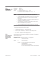
30 [xx]
30 UUUU ...
xx =
not coded = Return Status Words 1 through 15.
01 = Return Status Words 16 through 30.
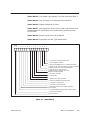
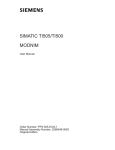
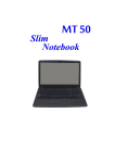
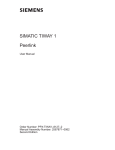
Response contains 15 status words with the following definitions:
MSB
A B
C
D
E
F
H
I
G
Scan Time in Milliseconds (8 Bits)
Download Select Switch (1 = Download)
Fatal Error Present (1 = Fatal)
Hold Mode (1= Hold)
User Program Source (RAM/ROM) (1 = ROM)
Battery Low (1 = Low Battery)
Operational Mode (Program/Run) (1 = Run)
Scan Type (Fixed/Variable) (1 = Fixed)
Keylock Protected (1 = Protected)
Figure 2-1 Status Word 1
2-2
Task Code Definitions
TI575 Task Code
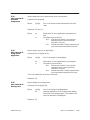
The scan time reported in field G is modulo 256 in earlier controller
releases.
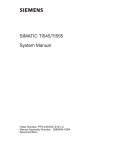
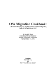
Fatal Error where the bit = 1 means:
MSB
A B
C
D
E
F
G
H
I
J
K
L
M
N
O
P
Operating System RAM Parity
Program RAM Parity
Operating System Fatal Error
Watchdog Timeout
Dynamic Program Memory Diagnostic
Illegal Operation Code
RAM Diagnostic Failure
ROM Diagnostic Failure
Scan Diagnostic Failure
I/O Fatal Error
Reserved
Abnormal Power Loss
Unindentified Failed Board Present (TI560/565)
Fatal Error due to EPROM
Other Hardware Failures
Fatal Error (see Status Word 16 for reason code)
Figure 2-2 Status Word 2
TI575 Task Code
Task Code Definitions
2-3
Task Code Definition (continued)
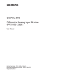
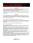
Fatal Error where the bit = 1 means:
MSB
A A
A
A
B
C
D
E
F
G
H
I
J
K
L
M
Scan Overrun
I/O Base Failure
Special Function Port Failure
Local Port Communication Port Failure
I/O Module Failure
Over Temperature
Too Many Special Function Modules
I/O Table Does Not Agree With Modules Installed
Board Marked Non-fatal has Failed
Untraceable Error Flag Set
User Program Error (See Chapter 2, STW200)
Non-Fatal Error (See Status Word 17 for reason code)
Controller Type (see Table C–6)
Figure 2-3 Status Word 3
Table 2-1 Controller Type
2-4
0000
5TI
0001
Reserved
0010
SIMATIC TI520/TI525
0011
SIMATIC TI530/TI535
0100
SIMATIC TI545/TI555
0110
SIMATIC TI560/TI565
0111
SIMATIC TI575
1000 – 1101
Future Expansions
1110
Non-Programmable Controller
1111
PM550
Task Code Definitions
TI575 Task Code
Status Word 4: The Ladder Logic Memory Size. (See also Status Word 7).
Status Word 5: User V memory Size. (See also Status Word 12.)
Status Word 6: Highest configured I/O Point.
Status Word 7: Most significant 16 bits of the Ladder Logic Memory Size.
Concatenated with Status Word 4 to indicate memory sizes larger than
65,535 words.
Status Word 8: Remaining I/O points not configured.
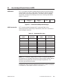
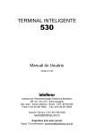
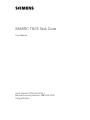
Status Word 9: Expanded Controller Type Identification.
MSB
A B
C
D
E
F
G
H
I
J
K
L
M
N
O
P
1 = Controller is Compiled Code Version
1 = SF/Loop Option Installed
1 = Remote I/O QQQQ format, 0 = Distributed Format
1 = Block transfer uses data element type with 24 bit offset
0 = Block transfer uses 16 bit absolute address
1= NIMs are Local, Control is Local
0 = NIM in Remote, Network has Control
Multiple Controllers Installed
1 = 5x5 Class Controller
1 = Internal CRs
1 = Network Time Slice supported
1 = Generic Upload/Download Supported
1 = Controller in Upload Mode
1 = Controller in Download Mode
1 = Transparent Byte Protocol (TBP) supported
(for local ports)
1 = Loop Data Elements Supported by Block Transfer
1 = STW 16–30 supported
Spare, Set to Zero
Figure 2-4 Status Word 9
TI575 Task Code
Task Code Definitions
2-5
Task Code Definition (continued)
Status Word 10: HBU Mode.
0001
Active with no Standby (Stand Alone)
0002
Active with Off-line Standby
0003
Active with On-line Standby
0004
Standby On-line with healthy Active
0005
Standby Off-line with healthy Active
Status Word 11 (Valid only if Word 10 = 2 or 5): Reason for Off-line.
0000
No special reason (entered on power up)
0001
Off-line due to hardware mismatch
0002
Off-line due to user command
0003
Off-line due to active unit in PROGRAM mode
0004
Off-line requesting on-line but inhibited by user program in active unit
0005
Off-line due to failure in standby
0006
Off-line due to loss of HBU communications
Status 12: Most significant 16 bits of the User V memory size.
Concatenated with Status Word 5 to indicate memory sizes larger than
65535 words.
Status Word 13 and 14: Operational status of each card in a multicard
chassis. The numbered bits below represent the corresponding physical slot
within the controller. If the bit is 0, a card is installed and functional. If the
bit is 1, the card is failed or not present.
x
LSB
WORD 13
MSB
15
14
13
12
11
10
9
8
7
6
5
4
3
2
1
26
25
24
23
22
21
20
19
18
17
16
WORD 14
x
2-6
Task Code Definitions
30
29
28
27
TI575 Task Code
Status Word 15: Peak discrete scan for a TI545, TI555, or TI575. It has no
meaning for the other controllers. It is the peak time required to execute the
I/O Cycle, RLL and SF Cycle for a TI545, TI555, or TI575.
Status Word 16: Provides the reason for fatal error if bit ‘‘A” in Status
Word 2 is set. Error numbers range from 0 to 65535.
Status Word 17: Provides the reason for non-fatal error if bit “B” in Status
Word 3 is set. Error numbers range from 0 to 65535.
Status 18 thru 30: Undefined and are set to zero.
TC32
Program to Run
Mode
Command:
Response:
32
32
TC33
Go to Program
Mode
Command:
Response:
33 xx
33 xx
xx
TC34
Execute Power-up
Command:
Response:
if 00 freezes the outputs
if FF clears the discrete outputs and freezes the word
34 [xx]
34
Field xx is added for multi-PLC/multi-application systems (e.g., TI575) and
has the following characteristics:
If xx is not coded or xx = 00, then the restart is for this application only.
If xx = 01, then the restart is coordinated across locked applications.
If xx = 02, then the restart is coordinated across all applications
independent of dependencies.
If xx is not specified then 00 is assumed unless the PLC is in the
FAULT mode, then 02 is assumed for multiple application PLCs. If the
PLC is in the fault mode and xx is specified, it must be 02 or the restart
is disallowed.
If the battery is bad, 34 xx or 34 is not allowed in the RUN or HOLD
mode.
TI575 Task Code
Task Code Definitions
2-7
Task Code Definition (continued)
TC35
Execute Complete
(Warm) Start
Command:
Response:
35 [xx]
35
Field xx is added for multi-PLC/multi-application systems (e.g., TI575) and
has the following characteristics:
If xx is not coded or xx = 00, then the restart is for this application only.
If xx = 01, then the restart is coordinated across locked applications.
If xx = 02, then the restart is coordinated across all applications
independent of dependencies.
If xx is not specified then 00 is assumed unless the TI575 is in the
FAULT mode, then 02 is assumed.
If the PLC is in the fault mode and xx is specified, it must be 02 or the
restart is disallowed.
If the PLC is in the fault mode, xx = 02, and the battery is bad, then
the PLC memory is cleared.
TC36
Execute Partial
(Hot) Start
Command:
Response:
36 [xx]
36
Field xx is added for multi-PLC/multi-application systems (e.g., TI575) and
has the following characteristics.
If xx is not coded or xx = 00, then the restart is for this application only.
If xx = 01, then the restart is coordinated across locked applications.
If xx = 02, then the restart is coordinated across all applications
independent of dependencies.
If xx is not specified then 00 is assumed unless the TI575 is in the
FAULT mode, then 02 is assumed.
If the PLC is in the fault mode and xx is specified, it must be 02 or the
restart is disallowed.
If the PLC is in the fault mode, xx = 02, and the battery is bad, then
the PLC memory is cleared.
2-8
Task Code Definitions
TI575 Task Code
TC50
Read User Word
Area Block
Command:
Response:
50 AAAA
50 RRRR [RRRR] ...
As many locations are returned that can fit in the task code length or until
the end of the memory type is reached.
NOTE: For the TI545, TI555, and TI575 controllers, the wwww word code
descriptor can be used instead of the AAAA in which case the data
descriptor dddd replaces RRRR.
TC51
Write User Word
Area Starting at
Address
Command:
Response:
51 AAAA RRRR [RRRR] ...
51
As many locations can be written that fit in the task code length, or until
the end of the memory type is reached.
NOTE: For the TI545, TI555, and TI575 controllers, the wwww word code
descriptor can be used instead of the AAAA in which case the data
descriptor dddd replaces RRRR.
TI575 Task Code
Task Code Definitions
2-9
Task Code Definition (continued)
TC58
Set Controller Time
of Day Clock
Command:
Response:
Where
58 GGGG HHHH IIII JJ
58
GGGG = Year/Month =
bit
1
8
9
xxxx
xxxx
xxxx
xxxx
tens
ones
tens
ones
Year
HHHH = Day/Hour =
bit
Month
1
8
9
bit
xxxx
xxxx
xxxx
tens
ones
tens
ones
Hour
1
8
bit
9
16
xxxx
xxxx
xxxx
xxxx
tens
ones
tens
ones
Minute
JJ= Day of Week =
16
xxxx
Day
IIII = Min/Sec =
16
1
Second
8
xxxx
spare
2-10
Task Code Definitions
TI575 Task Code
TC59
Write Discrete I/O
Status via Data
Element Type
TC5A
Write Block
Command:
Response:
Where
59 TT JJJJJJ NN [nnnn] II [II] ...
59
TT =
Data Element Type Identifier
Value
Data Element Type
06
Discrete Input Packed (X)
07
Discrete Output Packed (Y)
08
Control Register Packed (CR)
JJJJJJ =
24 bit offset (first data element is 0)
NN =
Number of bits = 1 – 208 [short form]
= 255 indicates extended count in nnnn
nnnn =
Extended Number of bits. Only included if
NN = 255. (For use with line lengths greater than 72
characters.)
II =
Group of 8 discrete bits. The starting bit identified
by JJJJJJ is the LSB of the first II and increasing
discrete addresses are in increasing bit position
significance. Pattern is repeated in each byte.
Command:
Response:
5A wwww dddd [dddd] ...
5A
Description:
Write block beginning at the address specified by wwww.
NOTE: When writing loop or analog alarm data, the data corresponding to
undefined loops and analog alarms is ignored. It must be present in the
block as a placeholder.
TI575 Task Code
Task Code Definitions
2-11
Task Code Definition (continued)
TC6B
Read Discrete I/O
Status Using Data
Element Type
TC71
Read Controller
Time of Day Clock
Command:
Response:
Where
Command:
Response:
6B TT JJJJJJ NN [nnnn]
6B II [II] ...
TT =
Data Element Type Identifier (See TC 59)
JJJJJJ =
24 bit offset (first data element is 0)
NN=
=
Number of bits = 1 – 248 [short form]
255 indicates extended count in nnnn
nnnn =
Extended Number of bits. Only included if
NN = 255. (For use with line lengths greater than 72
characters.)
II =
Group of 8 discrete bits. The starting bit identified
by JJJJJJ is the LSB of the first II and increasing
discrete addresses are in increasing bit position
significance. Pattern is repeated in each byte.
Unused bits are cleared if number returned is not a
multiple of 8.
71
71 GGGG HHHH IIII JJ
For GGGG HHHH IIII JJ definition, see Task Code 58.
2-12
Task Code Definitions
TI575 Task Code
TC7D
Read SF/Loop
Processor Mode
Command:
Response:
7D
7D 00mm ffff nnnn ssssssss rrrrrrrr wwww xxxx
yyyy zzzz vvvv rrrr qqqq
Description:
TC7D returns the current operational mode of the Loop/SF
processor (or the Loop/SF function on single board
controllers such as the TI545). The fields returned follow:
mm
ffff
nnnn
ssssssss
rrrrrrrr
wwww
xxxx
yyyy
zzzz
vvvv
rrrr
qqqq
TC7E
Read Random
Mode Descriptor.
1... .... Loop card is following CPU’s operational mode
.1.. .... Loop card is in PROGRAM mode.
..1. .... Loop card is in RUN mode.
...1 .... Loop card is in HOLD mode.
.... 1... Loop card is in FAULT mode.
.... .000 Unused.
Fatal Error vector
Non-fatal error vector
Size of S-memory in bytes.
Number of bytes of S-memory available.
Maximum number of loops supported.
Maximum number of analog-alarms supported.
Maximum number of SF Programs supported.
Maximum number of SF Subroutines supported.
Control Block ID of the last undefined SF Program or SF
Subroutine that the user tried to execute. 0000 is returned if
no attempt has been made to execute an undefined SF
Program or SF Subroutine.
Control Block ID of the last restricted SF Program that the
user tried to invoke from RLL. 0000 is returned if no attempt
has been made to invoke a restricted SF Program from RLL
Control Block ID of the first disabled control block in
S-memory. 0000 is returned if there are no disabled control
blocks.
Command:
Response:
7E wwww [wwww] ...
7E dddd [dddd] ...
Description:
Read values given the the wwww fields. wwww may be
either normal Series 500 word codes or SF/Loop word codes.
NOTE: Real values for undefined loops or analog alarms are returned as a
NAN (Not A Number). Integer values for undefined loop or analog alarms
are returned as zero.
TI575 Task Code
Task Code Definitions
2-13
Task Code Definition (continued)
If an error occurs when reading a variable, TC7E returns an error response:
00 ee wwww
Where
TC7F
Read Block
ee is the error code and wwww is the word code on which the
error occurred. Note that wwww may be 16-, 32-, or 48-bits long.
If the error occurred because wwww was a partial word code at
the end of the task code then TC7E returns a full-sized
word code padded on the end with zeros.
Command:
Response:
7F wwww [nn]
7F dddd [dddd] ...
Description:
Read nn values beginning at the address specified by wwww.
wwww may be either a normal Series 500 word code or an
SF/Loop word code. If nn is not specified, then as many
values as can fit in the task code buffer are returned.
NOTE: Real values for undefined loops or analog alarms are returned as a
NAN. Integer values for undefined loops or analog alarms are returned as
zero.
TC88
Select Number of
SF Module Task
Codes Per Scan
Command:
Response:
Where
88 CN [CN] ...
88
C = Channel Number = 1, 2, 3, ... 8 or F
N = Number of Task Codes per Scan = 1, 2, 3, ... 8
NOTE: This allows a different number of task codes per scan for each
channel, but all SF modules on that channel are allowed the same number.
If an un-installed channel is programmed, a range error is returned.
The hex value of F for the channel number is a wild card and indicates the
I/O channel over which the request is received. If this request is from any
communication port (local or remote) other than an SF module, it is rejected
as containing invalid data.
2-14
Task Code Definitions
TI575 Task Code
TC89
Read Number of SF
Module Task
Codes Per Scan
Command:
Response:
89 [C0] ...
89 CN [CN] ...
Where
C = Channel Number = 1, 2, 3, ... 8 or F
N = Number of Task Codes per scan = 1, 2, 3, ... 8
NOTE: •
Multiple CNs are returned in the order of the coded C0s.
•
If C0 is note-coded in the request, then one CN is returned for
each of the installed channels in order of channel number
(2 per RCC).
•
If the channel is coded as F, the N for the channel over which
the request is received is returned.
•
If the requester is on a local port and codes the channel as F,
then an invalid data error is returned.
•
If an uninstalled channel is coded, a range error is returned.
The following restart/reset conditions apply.
TC8D
Subcommand 00 –
Read I/O Base
Enable/Disable
Status
•
Cold/Warm/Hot Restarts: Use previous value
•
Power-up with Low Battery: Default to 2 task codes per scan
•
PLC Clear: Default to 2 task codes per scan
Used to determine which bases are disabled in the system. All supported
channels are returned.
Command: 8D 00
Response: 8D 00 cc mmmm [cc mmmm] ... (all supported
channels returned).
Where
TI575 Task Code
cc
Channel number.
mmmm
Bit mask representing which bases are
enabled/disabled.
MSB = base 15; LSB = base 0 ;
Bit set = base enabled; Bit cleared = base disabled.
Task Code Definitions
2-15
Task Code Definition (continued)
TC8D
Subcommand 01 –
Write Mask to
Controller
Used to write I/O base enable/disable mask to controller.
Command: 8D 01 cc mmmm [cc mmmm] ...
Where
cc
Channel number to write mask to. Range: 1 thru
maximum channel number supported.
mmmm
Mask representing which bases to enable/disable
Bit set indicates base is to be enabled. Bit cleared
indicates base is to be disabled.
MSB = base 15; LSB = base 0;
Response: 8D 01 cc mmmm [cc mmmm] ...
Where
cc
Channel number being modified.
mmmm
Mask representing which active bases were
disabled. Bit set indicates that base was active.
MSB = base 15; LSB = base 0;
Error Response:
TC8D
Subcommand 02 –
Read I/O Base
Configuration
Used to determine which bases are configured in the system. All supported
channels are returned.
Command: 8D 02
Response: 8D 02 cc mmmm [cc mmmm] ... (all supported channels
returned).
Where
TC93
Assign/Deassign
Port
cc
Channel number.
mmmm
Bit mask representing configuration status.
MSB = base 15; LSB = base 0 ;
Bit set = base configured;
Bit cleared = base not configured.
Used to specify application-to-port assignments. This task code has three
subcommands:
00
01
02
2-16
00 0E Cannot disable base because
Run out of ROM is selected.
Task Code Definitions
Read port assignments.
Assign port to application.
Deassign port.
TI575 Task Code
TC93
Subcommand 00 –
Read Port
Assignments
Used to determine which applications a port is assigned to.
Command: 93 00 QQQQ
Where
QQQQ
Port ID of the port whose assignments are to be
read.
Response: 93 [ aa cc ] ...
Where
aa
cc
TC93
Subcommand 01 –
Assign Port to
Application
Application ID of the application assigned to the
port.
Connection type as follows:
00 =
Exclusive connection. Only a single
application may have an exclusive
connection to a port.
01 =
Shared connection. Multiple applications
may have shared connections to a port.
Used to assign a port to an application.
Command: 93 01 QQQQ aa [cc]
Where
QQQQ
Port ID of the port to be assigned.
aa
cc
Application ID of the application to be assigned.
Connection type as follows:
00 =
Exclusive connection. Only a single
application may have an exclusive
connection to a port.
01 =
Shared connection. Multiple applications
may have shared connections to a port.
If cc is not coded, then exclusive is assumed.
Response: 93
TC93
Subcommand 02 –
Deassign Port
Used to delete a port assignment.
Command: 93 02 QQQQ [aa]
Where
QQQQ
aa
Port ID of the port to be deassigned.
Optional application ID of the application whose
connection is to be deassigned. If not coded or 00h
then the requester is deassigned.
Response: 93
TI575 Task Code
Task Code Definitions
2-17
Task Code Definition (continued)
TC94
Configure Port
This task code is used to set the attributes (e.g., baud rate, character size,
parity, number of stop bits, and protocol) of a local port. This task code has
two subcommands:
00 Read local port configuration.
01 Set local port configuration.
TC94
Subcommand 00 –
Read Port
Configuration
This task code is used to read the configuration of a port.
Command: 94 00 QQQQ
Where
QQQQ
Port ID of the port whose configuration is to be read.
Response: 94 QQQQ pppp bbbbbbbb cc pp ss ff
QQQQ
Port ID of the port whose configuration is to be read.
pppp
Port protocol as follows:
0000 none
0001 TTY (e.g., a printer port).
0002 TBP secondary (includes NITP).
0003 TBP host (includes NITP).
bbbbbbbb Baud rate.
2-18
Task Code Definitions
cc
Character size not including any parity bits.
Typically 7 or 8.
pp
Parity as follows:
00 No parity.
01 Even parity.
02 Odd parity.
03 Mark parity.
04 Space parity.
ss
Number of stop bits as follows:
00 Bit synchronous.
01 1 stop bit.
02 1.5 stop bits.
03 2 stop bits.
ff
Flow control as follows:
1... .... DSR/DTR.
.1.. .... XON/XOFF.
TI575 Task Code
TC94
Subcommand 01 –
Set Port
Configuration
This task code is used to set the port configuration.
Command: 94 01 QQQQ pppp bbbbbbbb cc pp ss ff
Where
QQQQ
Port ID of the port to be configured.
pppp
Port protocol as follows:
0000 none
0001 TTY (e.g., a printer port).
0002 TBP secondary (includes NITP).
0003 TBP host (includes NITP).
bbbbbbbb Baud rate.
cc
Character size, not including any parity bits;
typically 7 or 8.
pp
Parity as follows:
00 No parity.
01 Even parity.
02 Odd parity.
03 Mark parity.
04 Space parity.
ss
Number of stop bits as follows:
00 Bit synchronous.
01 1 stop bit.
02 1.5 stop bits.
03 2 stop bits.
ff
Flow control as follows:
1... .... DSR/DTR.
.1.. .... XON/XOFF.
Response: 94
TI575 Task Code
Task Code Definitions
2-19
Task Code Definition (continued)
TC99
Write VME Memory
Area
Block/Random
Task code 99 provides a flexible mechanism to write to a VME address.
Command: 99 {am offset ccxx de...de} ...
Where
am = Access mode
00 = Short user access
A16 VME address modifier code
$29
01 = Short supervisory access
A16 VME address modifier code
$2D
02 = Medium user data
A24 VME address modifier code
$39
03 = Medium user program
A24 VME address modifier code
$3A
04 = Medium supervisory data
A24 VME address modifier code
$3D
05 = Medium supervisory program A24 VME address modifier code
$3E
offset = oooooooo 32-bit offset into either A16 or A24 space.
cc = Number of elements of size xx to be written.
xx = Size of data element to be written.
00 = Byte operation.
01 = Word operation.
02 = Long word operation.
de = Data element of size xx to be written.
Response: 99
Examples:
9900 00000120 0100 FF write 1 byte to A16 user space.
9902 00002000 0500 FF FF FF FF FF write 5 bytes to A24 user
data space using byte operations (i.e., writing 1 byte at a time).
2-20
Task Code Definitions
TI575 Task Code
TC9A
Read VME Memory
Area
Block/Random
Task code 9A provides a flexible mechanism to read from a VME address.
Command: 9A {am offset ccxx } ...
Where
am = Access mode
00 = Short user access
A16 VME address modifier code
$29
01 = Short supervisory access
A16 VME address modifier code
$2D
02 = Medium user data
A24 VME address modifier code
$39
03 = Medium user program
A24 VME address modifier code
$3A
04 = Medium supervisory data
A24 VME address modifier code
$3D
05 = Medium supervisory program A24 VME address modifier code
$3E
offset = oooooooo 32-bit offset into either A16 or A24 space.
cc = Number of elements of size xx to be read.
xx = Size of data element to be read.
00 = Byte operation.
01 = Word operation.
02 = Long word operation.
Response: 9A de...de
Where
de = Data element of size xx that was read.
Examples:
9A00 00000120 0100 read 1 byte from A16 user space.
9A02 00002000 0500 read 5 bytes from A24 user data space
using byte operations (i.e., reading 1 byte at a time).
TI575 Task Code
Task Code Definitions
2-21
Chapter 3
Communication Protocols
3.1
Overview . . . . . . . . . . . . . . . . . . . . . . . . . . . . . . . . . . . . . . . . . . . . . . . . . . . . . . . . . . . . . . . . . . . . . . .
3-2
3.2
Non-Intelligent Terminal Protocol (NITP) . . . . . . . . . . . . . . . . . . . . . . . . . . . . . . . . . . . . . . . . . .
3-3
NITP Format . . . . . . . . . . . . . . . . . . . . . . . . . . . . . . . . . . . . . . . . . . . . . . . . . . . . . . . . . . . . . . . . . . . .
NITP Character Set . . . . . . . . . . . . . . . . . . . . . . . . . . . . . . . . . . . . . . . . . . . . . . . . . . . . . . . . . . . . . .
Message Delimiters . . . . . . . . . . . . . . . . . . . . . . . . . . . . . . . . . . . . . . . . . . . . . . . . . . . . . . . . . . . . .
Character Count . . . . . . . . . . . . . . . . . . . . . . . . . . . . . . . . . . . . . . . . . . . . . . . . . . . . . . . . . . . . . . .
Message Body . . . . . . . . . . . . . . . . . . . . . . . . . . . . . . . . . . . . . . . . . . . . . . . . . . . . . . . . . . . . . . . . . .
Error-checking Code . . . . . . . . . . . . . . . . . . . . . . . . . . . . . . . . . . . . . . . . . . . . . . . . . . . . . . . . . . . .
3-3
3-3
3-4
3-4
3-4
3-4
Transparent Byte Protocol . . . . . . . . . . . . . . . . . . . . . . . . . . . . . . . . . . . . . . . . . . . . . . . . . . . . . . .
3-6
UART Initialization Requirements . . . . . . . . . . . . . . . . . . . . . . . . . . . . . . . . . . . . . . . . . . . . . . . . .
Message Format . . . . . . . . . . . . . . . . . . . . . . . . . . . . . . . . . . . . . . . . . . . . . . . . . . . . . . . . . . . . . . . .
Initiator . . . . . . . . . . . . . . . . . . . . . . . . . . . . . . . . . . . . . . . . . . . . . . . . . . . . . . . . . . . . . . . . . . . . . . . . .
Responder . . . . . . . . . . . . . . . . . . . . . . . . . . . . . . . . . . . . . . . . . . . . . . . . . . . . . . . . . . . . . . . . . . . . .
RL Byte . . . . . . . . . . . . . . . . . . . . . . . . . . . . . . . . . . . . . . . . . . . . . . . . . . . . . . . . . . . . . . . . . . . . . . . . .
LL Byte . . . . . . . . . . . . . . . . . . . . . . . . . . . . . . . . . . . . . . . . . . . . . . . . . . . . . . . . . . . . . . . . . . . . . . . . .
TC Byte . . . . . . . . . . . . . . . . . . . . . . . . . . . . . . . . . . . . . . . . . . . . . . . . . . . . . . . . . . . . . . . . . . . . . . . . .
Message Timeouts . . . . . . . . . . . . . . . . . . . . . . . . . . . . . . . . . . . . . . . . . . . . . . . . . . . . . . . . . . . . . .
Message Turn Around Time . . . . . . . . . . . . . . . . . . . . . . . . . . . . . . . . . . . . . . . . . . . . . . . . . . . . . .
Minimum Time Between Requests . . . . . . . . . . . . . . . . . . . . . . . . . . . . . . . . . . . . . . . . . . . . . . . .
Application Note for Parity Checking NITP Message . . . . . . . . . . . . . . . . . . . . . . . . . . . . . . .
3-6
3-6
3-6
3-6
3-6
3-7
3-7
3-8
3-8
3-8
3-9
3.3
TI575 Task Code
Communication Protocols
3-1
3.1
Overview
The Series 505 controllers support two serial communication protocols on
the RS-232 and RS-422 communication ports.
•
All Series 505/500: Non-Intelligent Terminal Protocol (NITP)
•
TI545/TI565/TI575: Transparent Byte Protocol (TBP).
Additionally, the TI575 supports the Interboard Communication Protocol
(IBC). Task codes are requested using any of the applicable protocols.
This chapter describes the operation of the NITP and the TBP protocols.
Refer to SIMATIC TI575 Interboard Communication Manual
(PPX:575–8103) for a description of the IBC protocol.
3-2
Communication Protocols
TI575 Task Code
3.2
Non-Intelligent Terminal Protocol (NITP)
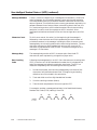
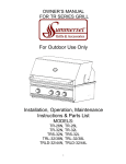
NITP Format
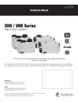
NITP is a simple, character-oriented method of data link communications
using standard 7-bit ASCII codes. Both command and response messages
consist of starting and ending delimiters, a character count or message
length field, the body of the message, and an error-checking code field as
shown in Figure 3-1.
Figure 3-1 Command and Response Messages
NITP Character Set
NITP uses the subset of standard ASCII codes (see Table 3-1) to
communicate with a wide variety of host devices, from ASCII terminals to
more intelligent machines.
Table 3-1 Standard ASCII Codes
7-bit ASCII
Code
Displayed
Character
7-bit ASCII
Code
Displayed
Character
30
0
39
9
31
1
3A
:
32
2
3B
;
33
3
41
A
34
4
42
B
35
5
43
C
36
6
44
D
37
7
45
E
38
8
46
F
NOTE: ASCII characters, except those in the NITP character set (e.g., a
carriage return or line feed), may be sent to control special network devices
between the ending delimiter and the next beginning delimiter. The
controller ignores these characters.
Hexadecimal values must be translated into two ASCII codes or characters:
For example, 0E (hex) equals 30 (ASCII 0) 45 (ASCII E).
TI575 Task Code
Communication Protocols
3-3
Non-Intelligent Terminal Protocol (NITP) (continued)
Message Delimiters
A colon (:) marks the beginning of a message and a semicolon (;) marks the
end of a message. Any characters between a colon and the next semicolon
are interpreted as valid; any characters between a semicolon and the next
colon are ignored. This allows the host to use any parameters required by its
software between lines of output. When transmitting data to the host, the
PLC sends carriage return and line feed characters after the terminating
semicolon in order to scroll the response on ASCII terminals. More
intelligent host devices can be set to filter out the carriage return and line
feed.
Character Count
To aid in error control, the colon (:) at the beginning of the message is
followed by a two-character count field representing the total number of
printable characters in the message, including the colon, character count,
message body, error checking code, and the terminating semicolon. The two
characters represent an 8-bit hexadecimal value so that a count of 50
characters is represented as 3332 (32 hex). The maximum length of NITP
messages is 72 characters.
Message Body
The message body consists of ASCII character pairs from the NITP
character set, each representing a single binary byte value.
Error-checking
Code
Following the message body is an ASCII four-character error-checking code
(ECC) in the form of a 16-bit hexadecimal number that is included at the
end of the message just before the semicolon terminator. The ECC is a
checksum computed by both the sending and receiving stations:
1.
Divide the character count and the message body into blocks of four
characters, left-justified and zero-filled. The beginning and ending
delimiters are not included in the calculation.
2.
Treat each block as a four-digit hexadecimal number.
3.
Sum the resulting numbers (blocks).
4.
Take the two’s complement of the sum to get the ECC.
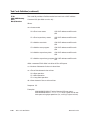
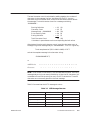
For example, consider a message whose body is the Read Word Memory
Random Task Code (TC01) reading V1 and V9:
3-4
Communication Protocols
TI575 Task Code
The total character count is calculated by adding together the number of
characters in the message, the four characters for the ECC, the two
characters for the character count, and the two characters used to delimit
the message. The total character count for a message containing
“0100000008” :
01
02
0A
04
01
: =
=
=
=
; =
Starting Delimiter
Character Count
Message Body – 0100000008
Error-checking Code
Ending Delimiter
Total Character Count
(1)*
(2)
(10)
(4)
(1)
12 (18)
* Numbers in parentheses are the corresponding decimal values.
After determining the total character count, insert the character count at
the beginning of the message body as “120100000008”. The ECC is given by:
Two’s complement of (1201 + 0000 + 0008) = EDF7
so that the complete message is the character string:
:120100000008EDF7;
or
3A 31 32 30 31 30 30 30 30 30 30 30 38 45 44 46 37 3B
: 1
2
0
1
0
0
0
0
0
0
0
8
E
D
F
7
;
NOTE: If the number of characters in the concatenated character count and
message body string is not evenly divisible by 4, then the fill characters ‘‘00”
are added to the end of the string for use in the ECC calculation. These fill
characters are not actually placed in the final message.
Table 3-2 summarizes the NITP message structure:
Table 3-2 NITP Message Structure
Field
TI575 Task Code
Contents
No. of Characters
Beginning delimiter
Colon (:)
1
Character count
Hexadecimal
2
Body of Message
Hexadecimal
72 (maximum)
Error Checking Code
Hexadecimal
4
Terminator
Semicolon (;)
1
Communication Protocols
3-5
3.3
Transparent Byte Protocol
Transparent Byte Protocol (TBP) is a message protocol for point-to-point
communications using 8-bit characters transmitted serially. Compared to
NITP, TBP improves the efficiency of the information exchange between a
controller and an operator interface device.
UART Initialization
Requirements
Message Format
In order to support TBP information exchange, the communications
controlling device, Universal Asynchronous Receiver-Transmitter (UART),
is initialized to the following conditions:
•
8 data bits per character
•
no parity
•
1 start bit
•
1 stop bit
The TBP message format is implemented as:
3F RL LL TC dd dd ... dd CK SM
The 3F or ASCII question mark is the first character of all TBP messages.
The first byte serves as the protocol identifier that allows the NITP
messages to be distinguished from the TBP messages. Therefore, any device
supporting TBP initializes the UART (described above). If the protocol is
NITP, the first byte received is hexadecimal BA or the ASCII colon sent with
odd parity. If the protocol is TBP, the first byte is hexadecimal 3F or the
ASCII question mark. Any other first character causes the message to be
discarded.
Initiator
The initiator of a request message may choose to use either protocol (NITP
or TBP). The responder must respond to the initiator in like protocol. In the
case that the request was made using TBP and the responder does not
support TBP, no response to the request is made.
Responder
For the responder that supports TBP, a request made using NITP is
acknowledged using NITP. Since the NITP character set is limited to 20
characters, the responder makes provisions to check parity even though the
UART is set up as defined above.
RL Byte
The RL byte defines the request/response maximum length in bytes. In a
message that is a task code request, the RL byte specifies the maximum
length of the task code response. In the task code request, the RL byte is a
binary number ranging from 6 (hexadecimal 06) to 256 (hexadecimal 00)
with 255 being represented by hexadecimal FF. In the task code response,
the RL byte defines the maximum length of response that the device
supports. Only two values are allowed for the RL byte in the response. The
values are 73 (hexadecimal 49) or 256 (hexadecimal 00).
3-6
Communication Protocols
TI575 Task Code
With this definition, a responding device with a maximum buffer size of 72
bytes indicates this restriction to the requesting device. In the event that
the request has overflowed the 72 byte buffer length, the responding device
returns error code hexadecimal 09 (incorrect amount of data sent with
request).
LL Byte
The LL byte defines the message byte count including the 3F and the
CKSM. The byte count is a hexadecimal number ranging from a minimum
of 6 (hexadecimal 06) to a maximum of 256 (hexadecimal 00) with 255
represented by hexadecimal FF.
TC Byte
The TC byte is a hexadecimal number ranging from 00 to FF that identifies
the task code command/response message.
The dd dd ... dd bytes is a hexadecimal number representing the data
associated with the task code request/response.
The CK and SM bytes form hexadecimal numbers ranging from 0 to 255.
The checksum bytes are generated by the sending device using the Fletcher
checksum one’s complement as defined by the following equation. The
exclamation point preceding the sum of the terms in parentheses in the
equation for CK means to take the one’s complement of the resulting sum.
CK = !(B1 + B2 + B3 + ...+ Bn + SM)
SM = (n)B1 + (n - 1)B2 + (n - 2)B3 + ... + Bn
When a carry results from adding two bytes, the carry is added into the sum
or the sum is incremented by one. For instance, if the message consisted of
the following bytes:
3F 49 06 30
CK is calculated as !(3F + 49 + 06 + 30 + 15) = 2C.
SM is calculated as 4*3F + 3*49 + 2*06 + 30 = 15.
The transmitted message becomes: 3F 49 06 30 2C 15.
The receiver calculates both the CK and the SM checksum bytes, for
example:
CK = B1 + B2 + B3 + ...+ Bn
SM = (n)B1 + (n - 1)B2 + (n - 2)B3 + ... + Bn
TI575 Task Code
Communication Protocols
3-7
Transparent Byte Protocol (continued)
When a carry results from adding two bytes, the carry is added into the sum
or the sum is incremented by one. For the transmitted message from the
above example, the receiver produces the following results:
CK is calculated as 3F + 49 + 06 + 30 + 2C + 15 = FF.
SM is calculated as 6*3F + 5*49 + 4*06 + 3*30 + 2*2C + 15 = FF.
If the checksum calculated by the receiver does not equal hexadecimal FF,
an error has occurred and the message is discarded.
Message Timeouts
The receiver starts a timer upon receiving of the first character of a
message. If the entire message is not received before the timer times out,
the message is discarded and the receiver is initialized to receive the next
message. The timeout value is baud rate dependant and message length
dependant. The values for the maximum length message are shown in
Table 3-3, along with the baud rate and character times.
Table 3-3 Maximum Length Message Values
Baud Rate
Character Time (ms)
Message Timeout Value (sec)
19,200
0.521
0.150
9,600
1.042
0.300
2,400
4.167
1.200
1,200
8.333
2.400
300
33.333
9.600
Message Turn
Around Time
After receiving a message, the response is not initiated for 0.25 ms. This
turn-around time ensures that the transmitting device has had time to set
up the receiver. The same delay applies between receiving the response and
the beginning of a new message.
Minimum Time
Between Requests
After a request message has been sent, the requester waits a minimum of
one message timeout, plus one turn around delay, before attempting another
transmission. This allows the receiver to timeout the first message and
re-initialize to receive. The time required to execute the request is
determined separately and may be much longer.
3-8
Communication Protocols
TI575 Task Code
Application Note
for Parity Checking
NITP Message
Since a device that supports TBP must also support NITP, use lookup tables
to avoid reprogramming the UART to send and receive 7 bits of data with
odd parity. For transmission, the hexadecimal ‘‘nibble” value is used as an
index into the table that contains the hexadecimal representation of the
ASCII character. The values of the ASCII characters used in NITP are listed
in Table 3-4.
Table 3-4 ASCII Character Values for NITP
ASCII Character
(or ‘‘Nibble’’)
Hexadecimal Representation With Parity
0
B0
1
31
2
32
3
B3
4
34
5
B5
6
B6
7
37
8
38
9
B9
A
C1
B
C2
C
43
D
C4
E
45
F
46
:
BA
;
3B
<CR>
0D
<LF>
8A
For reception, make a copy of the received character, mask the parity bit,
and convert it to a hexadecimal nibble. Using this nibble value as an index
into the transmit table, compare the received character with the table value.
If they do not match, an error occurred.
TI575 Task Code
Communication Protocols
3-9