1
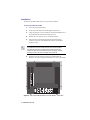
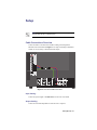
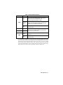
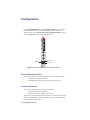
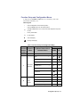
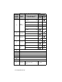
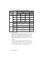
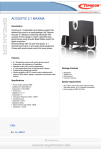
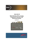
DAC-9213-PVM Multi-Definition SDI to Analog Component Converter for Sony® Monitors User Manual DAC-9213-PVM User Manual • Ross Part Number: 9213PVMDR-004-03 • Release Date: November 6, 2012. The information contained in this manual is subject to change without notice or obligation. Copyright © 2012 Ross Video Limited. All rights reserved. This work is proprietary and confidential to Ross Video Limited, its subsidiaries and its other affiliated corporations and may not be copied, distributed, sold or otherwise used or relied upon without the express written permission of Ross Video Limited. Reproduction or reverse engineering of copyrighted software is prohibited. Patents This product is protected by the following US Patents: 4,205,346; 5,115,314; 5,280,346; 5,561,404; 7,034,886; 7,508,455; 7,602,446; 7,834,886; 7,914,332. This product is protected by the following Canadian Patents: 2039277; 1237518; 1127289. Other patents pending. Notice The material in this manual is furnished for informational use only. It is subject to change without notice and should not be construed as commitment by Ross Video Limited. Ross Video Limited assumes no responsibility or liability for errors or inaccuracies that may appear in this manual. Trademarks • • 1 is a registered trademark of Ross Video Limited. is a trademark of Ross Video Limited. • Ross, ROSS, ROSS®, and MLE are registered trademarks of Ross Video Limited. • Sony® is a trademark of Sony Corporation. • VELCRO® is a registered trademark of Velcro Industries B.V. • All other product names and any registered and unregistered trademarks mentioned in this manual are used for identification purposes only and remain the exclusive property of their respective owners. Important Regulatory and Safety Notices to Service Personnel Before using this product and any associated equipment, refer to the “Important Safety Instructions” listed below to avoid personnel injury and to prevent product damage. Product may require specific equipment, and/or installation procedures to be carried out to satisfy certain regulatory compliance requirements. Notices have been included in this publication to call attention to these specific requirements. Symbol Meanings Protective Earth — This symbol identifies a Protective Earth (PE) terminal, which is provided for connection of the supply system’s protective earth (green or green/yellow) conductor. This symbol on the equipment refers you to important operating and maintenance (servicing) instructions within the Product Manual Documentation. Failure to heed this information may present a major risk of damage or injury to persons or equipment. Warning — The symbol with the word “Warning” within the equipment manual indicates a potentially hazardous situation which, if not avoided, could result in death or serious injury. Caution — The symbol with the word “Caution” within the equipment manual indicates a potentially hazardous situation which, if not avoided, may result in minor or moderate injury. It may also be used to alert against unsafe practices. Warning Hazardous Voltages — This symbol is intended to alert the user to the presence of uninsulated “dangerous voltage” within the product enclosure that may be of sufficient magnitude to constitute a risk of shock to persons. ESD Susceptibility — This symbol is used to alert the user that an electrical or electronic device or assembly is susceptible to damage from an ESD event. 2 Important Safety Instructions 1. Warning – Read these instructions. 2. Keep these instructions. 3. Heed all warnings. 4. Follow all instructions. 5. The safe operation of this product requires that a protective earth connection be provided. A grounding conductor in the equipment's supply cord provides this protective earth. To reduce the risk of electrical shock to the operator and service personnel, this ground conductor must be connected to an earthed ground. 6. Do not defeat the safety purpose of the grounding-type plug. A grounding type plug has two blades and a third grounding prong. The third prong is provided for your safety. If the provided plug does not fit in to your outlet, consult an electrician for replacement of the obsolete outlet. Protect the power cord from being walked on or pinching particularly at plugs, convenience receptacles, and point where they exit from the apparatus. 7. Warning – Indoor Use: WARNING: To reduce the risk of fire or electric shock, do not expose this apparatus to rain or moisture. 8. Do not block ventilation openings. Install in accordance with manufacturer's instructions. 9. Do not install near heat sources such as radiators, heat registers, stoves, or other apparatus (including amplifiers) that produce heat. 10. Do not use this apparatus near water. 11. Only use attachments/accessories specified by the manufacturer. 12. Unplug this apparatus during lightning storms or when unused for long periods of time. 13. Clean only with a dry cloth. 14. To avoid electrical shock, disconnect the A/C power cord before any servicing. 15. Refer all servicing to qualified personnel. Servicing is required when the apparatus has been damaged in any way, such as power-supply cord or plug damage, liquid has been spilled or objects have fallen into the apparatus, the apparatus has been exposed to rain or moisture, does not operate normally, or has been dropped. 3 EMC Notices United States of America FCC Part 15 This equipment has been tested and found to comply with the limits for a class A Digital device, pursuant to part 15 of the FCC Rules. These limits are designed to provide reasonable protection against harmful interference when the equipment is operated in a commercial environment. This equipment generates, uses, and can radiate radio frequency energy and, if not installed and used in accordance with the instruction manual, may cause harmful interference to radio communications. Operation of this equipment in a residential area is likely to cause harmful interference in which case the user will be required to correct the interference at his own expense. Notice — Changes or modifications to this equipment not expressly approved by Ross Video Limited could void the user’s authority to operate this equipment. CANADA This Class “A” digital apparatus complies with Canadian ICES-003. Cet appariel numerique de la classe “A” est conforme a la norme NMB-003 du Canada. EUROPE This equipment is in compliance with the essential requirements and other relevant provisions of CE Directive 93/68/EEC. INTERNATIONAL This equipment has been tested to CISPR 22:1997 along with amendments A1:2000 and A2:2002, and found to comply with the limits for a Class A Digital device. Notice — This is a Class A product. In domestic environments, this product may cause radio interference, in which case the user may have to take adequate measures. Maintenance/User Serviceable Parts Routine maintenance to this GearLite product is not required. This product contains no user serviceable parts. If the module does not appear to be working properly, please contact Technical Support using the numbers listed under the 4 “Contact Us” section on the last page of this manual. All GearLite products are covered by a generous 3-year warranty and will be repaired without charge for materials or labor within this period. See the “Warranty and Repair Policy” section in this manual for details. Environmental Information The equipment that you purchased required the extraction and use of natural resources for its production. It may contain hazardous substances that could impact health and the environment. To avoid the potential release of those substances into the environment and to diminish the need for the extraction of natural resources, Ross Video encourages you to use the appropriate take-back systems. These systems will reuse or recycle most of the materials from your end-of-life equipment in an environmentally friendly and health conscious manner. The crossed-out wheeled bin symbol invites you to use these systems. If you need more information on the collection, reuse, and recycling systems, please contact your local or regional waste administration. You can also contact Ross Video for more information on the environmental performances of our products. 5 Introduction Overview The DAC-9213-PVM Multi-Definition SDI to Analog Component Converter for Sony® Monitors is a high-quality signal conversion solution for High Definition (HD) and Standard Definition (SD) SDI signals and part of a growing family of GearLite Multi-Definition (MD) self-contained, small brick format modules. The DAC-9213-PVM is designed to fit into an HD-compatible Sony® monitor’s adapter input slot. The DAC-9213-PVM provides a monitoring-quality MD-SDI component monitoring solution in a small, stand-alone package. The DAC-9213-PVM addresses program stream imaging requirements by converting 10bit MD-SDI video to analog component video (multiple formats). The DAC-9213-PVM has a full 10bit data path, with 11bit data processing. The front panel of the DAC-9213-PVM chassis provides power and status LEDs for visual reference. In addition, user-selectable switch settings are available to select the preferred mode of operation. The DAC-9213-PVM provides analog conversion of 525i, 625i, 720p, 1080i, and 1080p SDI signals (SMPTE 259M and SMPTE 292M). The DAC-9213-PVM also has two re-clocked SDI outputs. Special measures have been taken to ensure excellent return loss at both input and output. This ensures error-free performance with short or long cables. Simplified Block Diagram ANLG CVBS Y/G OUT SDI IN EQ RECLOCKER & DESERIALIZER CONVERSION MATRIX & PROCESSING ANLG CVBS PB/B OUT ANLG CVBS PR/R OUT RECLOCKED SDI OUT 1 RECLOCKED SDI OUT 2 Figure 1 Simplified Block Diagram of DAC-9213-PVM Functions Introduction (Iss. 03) • 6 Features The DAC-9213-PVM includes the following features: • • • • • • HD-SDI and SD-SDI to analog component conversion 2 reclocked SDI outputs 10bit DAC resolution 11bit data processing Automatic input cable equalization >300m (>984ft) of Belden 1694A at SD-SDI rates (270Mbps) Automatic input cable equalization >100m (>328ft) of Belden 1694A at HD-SDI rates (1.485Gbps) Analog component outputs can be set for YPBPR or RGB • • • • • Sony® monitor input slot compatible form factor LEDs for power and status Small brick form factor 5V universal adapter with locking DC connector 3-year warranty • 7 • Introduction (Iss. 03) Installation Static Discharge Whenever handling the DAC-9213-PVM and other related equipment, please observe all static discharge precautions as described in the following note: ESD Susceptibility — Static discharge can cause serious damage to sensitive semiconductor devices. Avoid handling circuit boards in high static environments, such as carpeted areas, and when wearing synthetic fiber clothing. Always exercise proper grounding precautions when working on circuit boards and related equipment. Unpacking Unpack each DAC-9213-PVM module you received from the shipping container and check the contents to ensure that all items are included. If any items are missing or damaged, contact your sales representative or Ross Video directly. Compatibility The DAC-9213-PVM is compatible with Sony® monitors which can accept Sony® model BKM-120D SDI and BKM-142 HD-SDI input modules. Table 1 lists the models supported by the DAC-9213-PVM. Table 1 Supported Sony® Monitors Model Description BVM-D9H1U / 5U 9”, 4x3, HD Capable BVM-D14H1U / 5U 14”, 4x3, HD Capable BVM-14L5/1 14”, 4x3, HD Capable BVM-20L5/1 20”, 4x3, HD Capable PVM-14L5/1 14”, 4x3, HD Capable PVM-20L5/1 20”, 4x3, HD Capable Installation (Iss. 03) • 8 Installation The DAC-9213-PVM installs on the rear of your Sony® monitor. To install the DAC-9213-PVM 1. Power off your Sony® monitor. 2. On the rear of the monitor, locate the adapter input slot (s). 3. Using your fingers or a slot screwdriver, unscrew the thumbscrews at the top and bottom of the left most input slot cover. 4. Remove the cover and store it in a convenient location. 5. Insert the DAC-9213-PVM in the left most slot until the edge connector on the rear of the module seats firmly in the monitor’s connector socket. Note — If any other Sony® option modules are installed, they must be installed from the left, and then the DAC-9213-PVM is installed. Sony® monitors will only recognize option modules from the left towards the right. If the monitor finds an option slot empty, it will not recognize any other modules to the right of the empty slot. 6. When the DAC-9213-PVM is seated level and flush with the monitor’s rear surface, tighten the thumbscrews to secure the module. STAT SDI IN SDI OUT 1 SDI OUT 2 PR/R PB/B Y/G UP FN DOWN DAC-9213-PVM PWR AC IN LINE A RGB/COMPONENT PARALLEL REMOTE IN G/Y OUT AUDIO IN VIDEO OUT IN OUT IN VIDEO OUT IN IN IN AUDIO OUT AUDIO B/PB R/PR OUT IN EXT SYNC OUT IN SERIAL REMOTE OUT OUT IN OUT AUDIO Figure 2 DAC-9213-PVM Installed in a Sony® Monitor - Rear View 9 • Installation (Iss. 03) Setup Note — Throughout this chapter, the term SDI is used universally to indicate either SD-SDI or HD-SDI signals. Cable Connections Overview Connect the cables to the DAC-9213-PVM according to the designations indicated on the chassis label and Figure 3. The input is internally terminated at 75ohm. It is not necessary to terminate unused outputs. STAT SDI IN SDI OUT 1 SDI OUT 2 PR/R PB/B Y/G UP FN DOWN DAC-9213-PVM PWR AC IN LINE A RGB/COMPONENT PARALLEL REMOTE IN G/Y OUT AUDIO IN VIDEO OUT IN VIDEO OUT IN IN IN OUT AUDIO IN OUT AUDIO B/PB R/PR OUT IN EXT SYNC OUT IN SERIAL REMOTE OUT OUT IN OUT AUDIO Figure 3 DAC-9213-PVM Connections Input Cabling Connect the system signal to the SDI IN BNC on the DAC-9213-PVM. Output Cabling Connect the reclocked output BNCs to other devices as required. Setup (Iss. 03) • 10 Using the supplied 3-BNC male to 3-BNC male 2m cable (727-008) or equivalent, connect the component video output from the DAC-9213-PVM to the corresponding component analog monitor input according to the designations indicated on the chassis faceplate and the monitor’s input BNCs. Refer to Figure 3. Note — The Sony® monitor component input must be selected, and the monitor must be set up for the same format as the DAC-9213-PVM output video format. Status and Selection LEDs The front edge of the DAC-9213-PVM has four LED indicators that display the status of the input signals, and indicate menu function and configuration selections. (Figure 4) STAT LED STAT SDI IN SDI OUT 1 SDI OUT 2 PR/R PB/B Y/G UP LED UP FN DOWN LED PWR LED DOWN DAC-9213-PVM PWR Figure 4 DAC-9213-PVM Front Edge Status Indicator LEDs Table 2 describes the status LEDs available on the DAC-9213-PVM. 11 • Setup (Iss. 03) LED STAT Table 2 Status LED Descriptions Color Function Green When lit, this LED indicates a valida input signal is present and no errors are detected. The DAC-9213-PVM is functioning correctly. Flashing Green When flashing green, this LED indicates an input signal problem or an inconsistency between the SDI input standard and the selected output format. Off When unlit, this LED indicates a loss of power to the DAC-9213-PVM. UP Yellow DOWN Yellow For menu items that have multiple selections, these LEDs will be in a state as indicated in the Function Setup and Configuration Menu. Green When lit, this LED indicates that the DAC-9213-PVM is powered on. Off When unlit, this LED indicates a loss of power to the DAC-9213-PVM. PWR a.*A valid signal is defined as any analog composite video signal standard input into the DAC-9213-PVM, which matches the setting of the Video Standard that has been selected in the Function Setup and Configuration Menu. In other words, if the converter is in its default state for NTSC (525/60) video, then only an NTSC (525/60) composite video signal input will cause the OK LED to be lit. Any other analog composite video signal, of a different standard (PAL-B, PAL-M, PAL N), that is input into the converter will be invalid. Setup (Iss. 03) • 12 Configuration Use the Function Select switch and the Down and Up buttons to configure the DAC-9213-PVM to convert analog video signals to SDI. Settings are described in the section “Function Setup and Configuration Menus” on page 14. Refer to Figure 5 for switch and button locations. STAT SDI IN SDI OUT 1 SDI OUT 2 PR/R PB/B Y/G Up Button UP FN Button FN DOWN Down Button DAC-9213-PVM PWR Figure 5 DAC-9213-PVM Switch and Button Locations General Operating Rules Please note the following important operating rules for the DAC-9213-PVM: • • The module is properly powered on. The module always powers-up in the last configuration used. Function Selection The factory-set default modes of operation are as follows: • • Input Video Standard = Auto Detect Output Video Format = YPBPR, N10 (no setup) In general only the Output Video Format needs to be set as desired. The default Auto-Detect input setting is extremely versatile. However, fixed mode settings are provided for user convenience. 13 • Configuration (Iss. 03) Function Setup and Configuration Menus A single press of the Down and Up buttons is a “momentary” click of the button unless indicated by “(h)”. Table Legend + Press the Up button from the default position – Press the Down button from the default position (h) Hold Up or Down button for 2-3 seconds for faster adjustment or special function * Factory default state Lit LED display Unlit LED display Flashing LED display Table 3 Function Setup and Configuration Menu Function Selection Function Switch Menu Position 0 1 Operation Input Video Standard LED Display Up/Down Buttons Mode Selection Menu Buttons perform no action Output Video Format UP 525i + 625i + 720p + 1080psf 23.98Hz, 1080psf 24Hz + 1080i 50Hz + 1080i 59.94Hz 1080i 60Hz + Auto detect* 2 DOWN RGB (NTSC Related) + RGB (MII) + RGB N10 (No setup) + YPBPR N10 (No setup)* Configuration (Iss. 03) • 14 Table 3 Function Setup and Configuration Menu Function Selection Function Switch Menu Position 3 Output Video Level LED Display Up/Down Buttons Mode Selection Menu DOWN Max. Gain +(h) Gain between Unity and Max. +(h) Unity* Gain between Min. and Unity –(h) Min. Gain –(h) On +(h) 4 Force Mono 5 Setup On 6 Syncon All 7 Disable Auto Mute 8 Not implemented 9 Not implemented A Not implemented B Not implemented C Not implemented D Not implemented E Not implemented F Default Set Off* On* Off – On + Off* 15 • Configuration (Iss. 03) UP On + Off* Reset all user settings to Factory Default state (Unity) +(h) See Notes Function Menu Notes Some of the menu items in Table 3 are explained here in further detail as follows: Operation In this menu position, the Down and Up buttons are disabled. Input Video Standard Use this menu item to select the video standard that matches the incoming SDI signal's video standard. In Auto Detect mode, the module will attempt to detect any of the supported incoming HD-SDI or SD-SDI video standards. Refer to Table 4 for supported standards. When a supported standard is detected, the appropriate analog output format is selected. If the module is unable to determine the input standard, the STATUS LED will flash and the module will mute the analog outputs. Note — If Disable Auto Mute is set to On with an input/output mismatch, the DAC-9213-PVM will output an invalid signal and the STATUS LED will flash. Output Video Format Use this menu to select the output component video format. Note that not all output formats support all SDI input signal standards. For example, RGB (NTSC Related) is only supported on 525i. Refer to Table 4 for a list of supported standards. Note — The Sony® monitor’s component input must be selected, and the monitor must be set up for the same format as the DAC-9213-PVM output video format. Configuration (Iss. 03) • 16 Table 4 Supported Formats and Input Standards Digital Input Standard 525i 625i HD (1080i, 720p) Analog Output Format YPBPR RGB Signal SMPTE/ EBU N10 MII NTSC Related SMPTE/ EBU N10 Y/G (setup) 0 to 700mV 0 to 700mV (54 to 700mV) 0 to 714mV (54 to 714mV) 0 to 700mV PB/B (setup) 0 to 700mV 0 to 700mV (54 to 700mV) 0 to 714mV (54 to 714mV) -350mV to +350mV PR/R (setup) 0 to 700mV 0 to 700mV (54 to 700mV) 0 to 714mV (54 to 714mV) -350mV to +350mV Sync 0 to -300mV 0 to -300mV 0 to -286mV 0 to -300mV Y/G 0 to 700mV 0 to 700mV PBPR/RB 0 to 700mV -350mV to +350mV Sync 0 to -300mV 0 to -300mV Y/G 0 to 700mV 0 to 700mV PBPR/RB 0 to 700mV -350mV to +350mV -300mV to +300mV -300mV to +300mV Sync Output Video Level Use this menu to adjust the component video output level by up to ± 25%. This setting affects all input standards and output formats. Pressing, or holding, the Up button will increase the output video level on all three analog output signals. Pressing, or holding, the Down button will decrease the output levels. This menu has a 2 button quick default to unity, the default value. Press both Up and Down buttons at the same time and hold for three seconds. Force Mono Use this menu to blank the PB and PR component output signals. This option has no function in RGB format. Note that if the DAC-9213-PVM is setup in RGB mode, and Force Mono is enabled, then the module is switched to YPBPR mode, the PB and PR channels will be blanked (i.e. the module remembers option settings even though they may not affect the current operating mode). 17 • Configuration (Iss. 03) Setup On Use this menu to control the blanking level of RGB signals in 525i mode only. Setup is only valid in the 525i RGB (MII) and 525i RGB (NTSC Related) output formats. Sync On All Use this menu to enable horizontal synchronization pulses (bi-level sync or tri-level sync), on all three RGB signals (Sync On All is set to On) or just on the Green channel (Sync On All is set to Off). Note — This setting has no effect on YPBPR signals. Disable Auto Mute Use this menu to disable automatic muting of the analog outputs when a standard mismatch occurs. When automatic muting is enabled (Disable Auto Mute = Off) the DAC-9213-PVM will automatically mute the analog outputs when the input video standard selected by the user differs from the video standard detected at the SDI input. Note — If Disable Auto Mute is set to On with an input/output mismatch, the DAC-9213-PVM will output an invalid signal and the STATUS LED will flash. Default Set Use this menu item to reset all user settings to the factory defaults. Holding down the Up button for three seconds will reset the user settings to the default values given in Table 3 on page 14. When selecting this option, the state of the UP LED will indicate if any settings are not in their default states. • • If the UP LED is flashing, it indicates there is at least one user setting that is not in its default state. If the UP LED is lit solid, the user settings are in default state. Configuration (Iss. 03) • 18 Specifications Specifications are subject to change without notification. Table 5 DAC-9213-PVM — Technical Specifications Category Parameter Specification Number of Inputs 1 Signal Standards Supported SMPTE 259M (270Mbps) SMPTE 292M (1.4835Gbps, 1.485Gbps) SD: 525i 5994Hz, 525i 60Hz, 625i 50Hz Serial Digital Video Input Signal Formats Supported HD: 720p 59.94Hz, 720p 60Hz, 1080psf 23.98Hz, 1080psf 24Hz, 1080i 50Hzz, 1080i 59.94Hz, 1080i 60Hz Input Impedance 75ohm terminating Return Loss >20dB to 270MHz >15dB to 1.485GHz Equalization (using Belden 1694A cable) >300m @ 270Mbps >100m @ 1.485Gbps Number of Outputs 2 reclocked Signal Standards Supported Follows SDI input, SMPTE 259M (270Mbps), SMPTE 292M (1.4835Gbps, 1.485Gbps) Output Impedance 75ohm terminating Return Loss Reclocked Serial Digital Video Output Signal Level >18dB to 270MHz >16dB to 1.485GHz 800mV ±10% DC Offset <±50mV Rise and Fall Time SD: <700ps typical HD: <270ps typical Overshoot/Undershoot <10% typical Outputs Short Circuit Protected Yes 19 • Specifications (Iss. 03) Table 5 DAC-9213-PVM — Technical Specifications Category Parameter Specification Analog Component Output Power Number of Outputs 3 Video Component Analog Video YPBPR or RGB Supported Video Levels YPBPR: SMPTE Output Impedance 75ohm Output Return Loss >45dB to 6MHz >28dB to 30MHz DC Offset for RGB or Component Video <±50mV Frequency Response ±0.5dB to 20MHz ±1.0dB to 30MHz Group Delay SD: <20ns to 6MHz HD: <6ns to 30MHz Outputs Short Circuit Protected Yes RMS Noise (unweighted) SD: <-55dB, 0-6.0MHz Required Voltage +6V DC, supplied by Sony® monitor Current Consumption <750mA typical Total Power <4.5W typical Thermal Environment 20°C to 40°C (68°F to 104°F), ambient, non-condensing Dimensions (approx.) 16.5cm x 5cm (6.5” x 2”) Other RGB: SMPTE, MII, Betacam Specifications (Iss. 03) • 20 Service Information Warranty and Repair Policy The GearLite DAC-9213-PVM is warranted to be free of any defect with respect to performance, quality, reliability, and workmanship for a period of THREE (3) years from the date of delivery to the customer. In the event that your GearLite DAC-9213-PVM proves to be defective in any way during this warranty period, Ross Video Limited reserves the right to repair or replace this piece of equipment with a unit of equal or superior performance characteristics. Should you find that this GearLite DAC-9213-PVM has failed after your warranty period has expired, we will repair your defective product should suitable replacement components be available. You, the owner, will bear any labor and/or part costs incurred in the repair or refurbishment of said equipment beyond the THREE (3) year warranty period. In no event shall Ross Video Limited be liable for direct, indirect, special, incidental, or consequential damages (including loss of profits) incurred by the use of this product. Implied warranties are expressly limited to the duration of this warranty. This DAC-9213-PVM User Manual provides all pertinent information for the safe installation and operation of your GearLite Product. Ross Video policy dictates that all repairs to the GearLite DAC-9213-PVM are to be conducted only by an authorized Ross Video Limited factory representative. Therefore, any unauthorized attempt to repair this product, by anyone other than an authorized Ross Video Limited factory representative, will automatically void the warranty. Please contact Ross Video Technical Support for more information. In Case of Problems Should any problem arise with your GearLite DAC-9213-PVM, please contact the Ross Video Technical Support Department. (Contact information is supplied at the end of this publication.) A Return Material Authorization number (RMA) will be issued to you, as well as specific shipping instructions, should you wish our factory to repair your GearLite DAC-9213-PVM. If required, a temporary replacement module will be made available at a nominal charge. Any shipping costs incurred will be the responsibility of you, the customer. All products shipped to you from Ross Video Limited will be shipped collect. The Ross Video Technical Support Department will continue to provide advice on any product manufactured by Ross Video Limited, beyond the warranty period without charge, for the life of the equipment. 21 • Service Information (Iss. 03) Notes: Service Information (Iss. 03) • 22 Contact Us Contact our friendly and professional support representatives for the following: • Name and address of your local dealer • Product information and pricing • Technical support • Upcoming trade show information Technical Support Telephone: +1 613 • 652 • 4886 After Hours Emergency: +1 613 • 349 • 0006 Email: [email protected] Telephone: +1 613 • 652 • 4886 General Information Fax: +1 613 • 652 • 4425 Email: [email protected] Website: http://www.rossvideo.com Visit Us Visit our website for: • Company information and news • Related products and full product lines • Online catalog • Testimonials