1
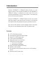
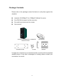
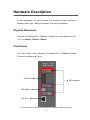
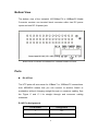
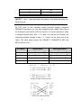
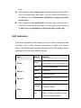
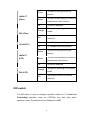
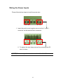
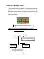
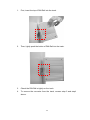
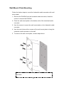
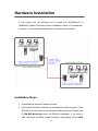
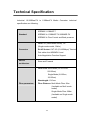
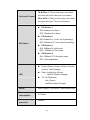
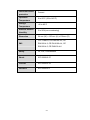
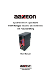
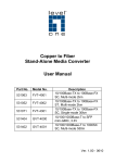
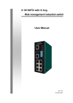
Industrial 10/100BaseTX to 100BaseFX Media Converter User Manual Rev.1.00 08-August-2006 FCC Warning This Equipment has been tested and found to comply with the limits for a Class A digital device, pursuant to Part 15 of the FCC rules. These limits are designed to provide reasonable protection against harmful interference in a residential installation. This equipment generates, uses and can radiate radio frequency energy and, if not installed and used in accordance with the instructions, may cause harmful interference to radio communications. However, there is no guarantee that interference will not occur in a particular installation. If this equipment does cause harmful interference to radio or television reception, which can be determined by turning the equipment off and on, the user is encouraged to try to correct the interference by one or more of the following measures: Reorient or relocate the receiving antenna. Increase the separation between the equipment and receiver. Connect the equipment into an outlet on a circuit different from that to which the receiver is connected. Consult the dealer or an experienced radio/TV technician for help. Content Introduction......................................................... 1 Features ................................................................... 1 Package Contents.................................................... 2 Hardware Description ......................................... 3 Physical Dimension.................................................. 3 Front Panel............................................................... 3 Bottom View ............................................................. 4 Ports......................................................................... 4 Cabling ..................................................................... 6 LED Indicators.......................................................... 7 DIP-switch ................................................................ 8 Wiring the Power Inputs ......................................... 10 Wiring the Fault Alarm Contact .............................. 11 Mounting Installation ........................................ 12 DIN-Rail Mounting.................................................. 12 Wall Mount Plate Mounting .................................... 14 Hardware Installation........................................ 15 Troubles shooting ............................................. 18 Technical Specification..................................... 19 Introduction Industrial 10/100BaseTX to 100BaseFX Media Converter is a costeffective solution for the converting 10/100Base-TX (Auto MDI/MDIX) to 100Base-FX cabling. It provides the two power inputs that can be connected simultaneously to the DC power sources. If one power input fails, the other one acts as a backup. Industrial 10/100BaseTX to 100BaseFX Media Converter also provides relay alarm outputs to warn when the port link failure, so the technician can respond quickly with appropriate emergency operation procedures. Also, there are DIP- switches to set the operation mode for relay alarm, Fiber ports, link loss forwarding function, and UTP operation mode. Features UTP to Fiber Media converter Auto Negotiation Speed and Half/Full Duplex Support 12 to 48VDC power inputs TX port support Auto MDI/MDI-X Relay alarm output for port link failure IEEE 802.3x flow control support ¾ Flow control on full-duplex ¾ Back pressure on half-duplex Built-in Link Lose Forwarding Technology DIN-Rail or wall mountable DIP-switches to set the operation mode and Link- Lost-Forwarding function. Redundant dual DC power Inputs 1 Package Contents Please refer to the package content list below to verify them against the checklist. Industrial 10/100BaseTX to 100BaseFX Media Converter One DIN-Rail (screwed on the converter) One wall mount plate and six screws User manual Industrial 10/100BaseTX to 100BaseFX Media Converter Wall Mount Plate Screws User Manual DIN-Rail Compare the contents of your industrial media converter with the standard checklist above. If any item is damaged or missing, please contact your local dealer for service. 2 Hardware Description In this paragraph, we will introduce the Industrial media converter’s hardware spec, port, cabling information, and wiring installation. Physical Dimension Industrial 10/100BaseTX to 100BaseFX Media Converter dimension (W x H x D) is 54mm x 135mm x 105mm Front Panel The Front Panel of the Industrial 10/100BaseTX to 100BaseFX Media Converter is showed as Figure. Fiber Port LED Indicator DIP Switch UTP Port Front Panel of the Industrial 10/100BaseTX to 100BaseFX Media Converter 3 Bottom View The bottom view of the Industrial 10/100BaseTX to 100BaseFX Media Converter consists one terminal block connector within two DC power inputs and one DC IN power jack. Bottom Panel of Industrial 10/100BaseTX to 100BaseFX Media Converter Ports RJ-45 Port The UTP ports will auto-sense for 10Base-T or 100Base-TX connections. Auto MDI/MDIX means that you can connect to another Switch or workstation without changing straight through or crossover cabling. See the Figure C and C-1 for straight through and crossover cabling schematic. RJ-45 Pin Assignments Pin Number Assignment 1 Tx+ 2 Tx- 4 3 Rx+ 6 Rx- [NOTE] “+” and “-” signs represent the polarity of the wires that make up each wire pair. All UTP ports on this Industrial media converter support automatic MDI/MDI-X operation, you can use straight-through cables (See Figure) for all network connections to PCs or servers, or to other switches or hubs. In straight-through cable, pins 1, 2, 3, and 6, at one end of the cable, are connected straight through to pins 1, 2, 3 and 6 at the other end of the cable. The table below shows the 10BASE-T/ 100BASE-TX MDI and MDI-X port pin outs. Pin MDI-X Signal Name MDI Signal Name 1 Receive Data plus (RD+) Transmit Data plus (TD+) 2 Receive Data minus (RD-) Transmit Data minus (TD-) 3 Transmit Data plus (TD+) Receive Data plus (RD+) 6 Transmit Data minus (TD-) Receive Data minus (RD-) Straight Through Cable Schematic Cross over Cable Schematic 5 Fiber Port This port is for 100Base-FX connections. We provide SC fiber connector in multi mode (2Km) or single mode (30Km) for different model number. When you connect the fiber port to another fiber port, please follow the below Figure D to connect it. Wrong connection will cause the port cannot work normally. ATTENTION This is a Class 1 Laser/LED product. Don’t stare into the Laser/LED Beam. Cabling Use the four twisted-pair, Category 5 cabling for RJ-45 port connection. The cable between the converter and the link partner (switch, hub, workstation, etc.) must be less than 100 meters (328 ft.) 6 long. Fiber segment using single-mode connector type must use 8/125 or 9/125 um single-mode fiber cable. You can connect two devices in the distance up to 30 Kilometers (Available on single mode fiber model only). Fiber segment using multi-mode connector type must use 50 or 62.5/125 um multi-mode fiber cable. You can connect two devices up to 2Km distances (Available on multi mode fiber model only). LED Indicators There are 8 diagnostic LEDs located on the Front panel of industrial media converter. They provide real-time information of system and optional status. The following table provides description of the LED status and their meanings for the industrial media converter. LED Status Meaning When the industrial switch has Green power input s the LED will light on Power Off No any power inputs Green Power on Off No power inputs Green Power on Off No power inputs Power 1 Power 2 Power failure or UTP port failure or Orange Fiber port failure Fault No Power failure or UTP port Off failure or Fiber port failure occurs or the port alarm disable 7 The port is linking with its link Green partner. LNK/ACT (Fiber) The port is transmitting or receiving Blinks packets from the FX device. Off No device attached The port is operating in full-duplex Orange mode. FDX (Fiber) Half-duplex mode or no device Off attached Green In 100Mbps transmitting speed Off In 10Mbps transmitting speed 10/100(UTP) The port is linking with its link Green partner. LNK/ACT (UTP) The unit is transmitting or receiving Blinks packets from the devices. Off No device attached The port is operating in full-duplex Orange mode. FDX (UTP) Half-duplex mode or no device Off attached DIP-switch The DIP-switch is used to configure operation mode for LLF (Link Lost Forwarding) operation mode for UTP/Fiber port and relay alarm operation mode. The default value of Dipswitch is OFF. 8 DIP Switch No Status ON 1 Description Enable Port Alarm. If the port’s link fails, the fault LED will light up. OFF Disable Port Alarm ON LLF Enable OFF LLF Disable ON 100Base-FX Half Duplex mode OFF 100Base-FX Full Duplex mode ON 100Base-TX Full Duplex mode OFF UTP Auto-Negotiation 2 3 4 Link Lose Forwarding: When LLF is enabling, allow UTP link failures to be reported to the fiber side and also allow Fiber link failure to be reported to the UTP side. Therefore, A link lost forward feature is provided in both UTP and Fiber side. [NOTE] Please don’t change the DIP-switch setting when UTP or fiber port is transmitting or receiving data. It may cause some data error. After change the DIP-switch setting, must execute Power OFF/ON to enable new configures. 9 Wiring the Power Inputs Please follow below steps to insert the power wire. V- V+ V- V+ 1. Insert the positive and negative wires into the V+ and Vconnector on the terminal block connector. 2. To tighten the wire-clamp screws for preventing the DC wires to loose. [NOTE] The wire range of terminal block is from 12~ 24 AWG. 10 Wiring the Fault Alarm Contact The fault alarm contact is in the middle of terminal block connector as below figure shows. By inserting the wires and set the DIPswitch at “ON” status, it will detect when power is failure or port link failure and form an open circuit. And, the following figure shows an application example for the fault alarm contact. 1A@24V Insert the wires into the fault alarm contact [NOTE] The wire range of terminal block is from 12~ 24 AWG. Fault Alarm Contact The open circuit will form when the power failure or port link failure. 24V DC Buzzer 24V Battery The fault alarm device will send a warning signal to warn the user, ex: alarm sound or flash light. 11 Mounting Installation DIN-Rail Mounting The DIN-Rail is screwed on converter when out of factory. If the DIN-Rail is not screwed on the converter, please see the following Figure F to screw the DIN-Rail on the converter. Follow the below steps to hang the converter. Rear Panel of the converter DIN-Rail 1. Use the screws to screw on the DIN-Rail on the converter. 2. To remove the DIN-Rail, reverse the step 1. Figure F 12 1. First, insert the top of DIN-Rail into the track. 2. Then, lightly push the button of DIN-Rail into the track. 3. Check the DIN-Rail is tightly on the track. 4. To remove the converter from the track, reverse step 2 and step1 above. 13 Wall Mount Plate Mounting Follow the below steps to mount the Industrial media converter with wall mount plate. 1. Remove the DIN-Rail from the Industrial media converter; loose the screws to remove the DIN-Rail. 2. Place the wall mount plate on the bottom side of the Industrial media converter. 3. Use the screws to screw the wall mount plate on the Industrial media converter. 4. Use the hook holes at the corners of the wall mount plate to hang the Industrial media converter on the wall. 5. To remove the wall mount plate, reverse steps above. Screws to screw the wall mount plate on the Industrial media converter 14 Hardware Installation In this section, we will describe how to install the 10/100BaseTX to 100BaseFX Media Converter and the installation points for the attention. In Figure, it is an example application for the Industrial converter. Installation Steps 1. Unpacked the Industrial media converter. 2. Check the DIN-Rail is screwed on the Industrial media converter. If the DIN-Rail is not screwed on the Industrial media converter. Please refer to DIN-Rail Mounting section for DIN-Rail installation. If you want to wall mount the Industrial media converter, then please refer to Wall 15 Mount Plate Mounting section for wall mount plate installation. 3. To insert the Industrial media converter into the track or hang on the wall, please refer to the Mounting Installation section. 4. Power on the Industrial media converter. How to wire the power; please refer to the Wiring the Power Inputs section. The power LED on the Industrial media converter will light up. Please refer to the LED Indicators section for meaning of LED lights. 5. Prepare the twisted-pair, straight through Category 5 cable for Ethernet connection and optic fiber cable for fiber connection. [NOTE] The Fiber port has single-mode and multi-mode. To check your Industrial media converter fiber connector type, look for the sticker on the Industrial media converter. The single-mode connector type must use 8/125 or 9/125 um single-mode fiber cable. The connect distance between two devices is up to 30 Km. The multi-mode connector type must use 50 or 62.5/125 um multi-mode fiber cable. The connect distance between two devices is up to 2Km. 6. Insert one side of Category 5 cables into the Industrial media converter Ethernet port (RJ-45 port) and another side of category 5 cables to the network switch’s Ethernet port (RJ-45 port). The UTP port (RJ-45) LED on the Industrial media converter will light up when the cable connected with the switch. Please refer to the LED Indicators section for LED light meaning. [NOTE] Be sure the connected local switch’s Ethernet port support MDI/MDI-X. If it does not support then use the crossover category-5 cable. 7. Insert one side of fiber cable into the Industrial media converter fiber port and another side to the convert in the opposite side connection. The fiber port LED on the converter will light up when the cable 16 connected. Please refer to the LED Indicators section for LED light meaning. 8. When all connections are all set and LED lights all show in normal, the installation is complete. 17 Troubles shooting Verify that you are using the right power cord/adapter (DC 12-48V). Please don’t use the power adapter with DC output bigger than 48V, or it will burn this converter down. Check the configuration DIP-switch. It must be setting in the same operation mode with the link partner. Select the proper UTP/Fiber cable to construct your network. The single-mode converter must use single-mode fiber cable. Please check that you are using the right cable. Don’t both use multi-mode and single mode. If the Industrial media converter LED indicators are normal and the connected cables are correct and the packets still cannot transmit. Please check your system’s Ethernet devices’ configuration or status. 18 Technical Specification Industrial 10/100BaseTX to 100BaseFX Media Converter technical specification are following. IEEE802.3 10BASE-T Standard IEEE802.3u 100BASE-TX/100BASE-FX IEEE802.3x Flow Control and Back pressure Fiber: SC (Multi-Mode model), SC (Single-mode model, 30Km) Connector RJ-45 Socket: CAT-3/5 (10/100Mbps) Twisted Pair cable Auto MDI/MDI-X and Auto-Negotiation Function Support Switch architecture Store and Forward Fiber Core: Multi-Mode (62.5/125um, 50/125um) Single-Mode (8/125um, 10/125um) Wavelength: 1310nm Fiber parameters Fiber Distance: Multi-Mode Fiber 2Km (Available on Multi mode model) Single-Mode Fiber 30Km (Available on Single mode model) 19 TX ÎFiber: If TX port link down, the media Link Lost Forward converter will force Fiber port to link down Fiber ÎTX: If Fiber port link down, the media converter will force TX port to link down. DIP Switch 1: ON: Enables Port Alarm OFF: Disables Port Alarm DIP Switch 2: ON: Enables LLF (Link Lose Forwarding) DIP Switch OFF: Disables LLF (Link Lose Forwarding) DIP Switch 3: ON: 100Base-FX Half-mode OFF: 100Base-FX Full-mode DIP Switch 4: ON: 100Base-TX Full-duplex mode OFF: Auto-Negotiation Power (Green), Power1 (Green), Power2 (Green), Fault (Orange) Fiber: Link/Activity (Green) Half/Full Duplex (Orange) LED TX: 10/100(Green) Link (Green) Half/Full Duplex (Orange) Power Power consumption Reserve polarity protection Input Voltage: 12 to 48VDC; Redundant inputs 4.6 Watts Present 20 Overload current protection Operation Temperature Storage Temperature Ambient Relative Humidity Dimension Present 0 to 60°C (32 to 140°F) -40 to 85°C 5 to 90%(non-condensing) 54 mm (W) x 135 mm (H) x 105mm (D) FCC Class A, CE EN6100-4-2, CE EMI EN6100-4-3, CE EN-6100-4-4, CE EN6100-4-5, CE EN6100-4-6 Safety UL, cUL, CE/EN60950 Shock IEC 60068-2-27 Free fall IEC 60068-2-32 Vibration IEC 60068-2-6 21