1
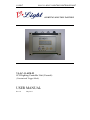
V LIGHT
VL-LC-11-4CH-P1 LIGHTING CONTROLLER UNIT
LIGHTING SOLUTION PARTNER
VL-LC-11-4CH-P1
4CH Lighting Controller Unit (Cascade)
(Constant and Trigger Mode)
USER MANUAL
Rev 1.0
May 2011
V LIGHT
VL-LC-11-4CH-P1 LIGHTING CONTROLLER UNIT
Contents
Hardware ........................................................................................................................................... 1
Packing List ................................................................................................................................... 1
Front Panel ..................................................................................................................................... 1
Connections.................................................................................................................................... 2
General Description ............................................................................................................................ 3
Specification ............................................................................................................................... 3
Power Input ................................................................................................................................ 3
Controller Mode ......................................................................................................................... 4
Operation ........................................................................................................................................... 5
Display Panel Control Mode ....................................................................................................... 5
USB/RS232 Control Mode .......................................................................................................... 9
LC-11 Cascade Operation ......................................................................................................... 11
Operation Description....................................................................................................................... 13
Timing Diagram ....................................................................................................................... 13
External Input Signal Control .................................................................................................... 14
Constant mode intensity to current table .................................................................................... 15
CABLE SELECTION ...................................................................................................................... 16
LIGHTING CONNECTORS ............................................................................................................ 16
LEDStudio DLL Documentation ...................................................................................................... 17
Revision Notes
Rev
1.0
Date/Author
KW/ Jonathan
Comment
Cascade - First Release
i
V LIGHT
VL-LC-11-4CH-P1 LIGHTING CONTROLLER UNIT
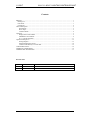
Hardware
Packing List
Please make sure that the following parts are in the packing list:
• LC-11 lighting controller unit
• USB/RS232 Cable (Optional One)
• Power Supply (Optional)
• 4 LED Lightings (Optional)
• 4 Ext. Cable 1.5 Meter (Optional)
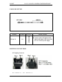
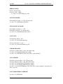
Front Panel
Page 1 of 29
V LIGHT
VL-LC-11-4CH-P1 LIGHTING CONTROLLER UNIT
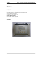
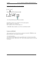
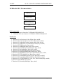
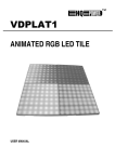
Connections
All connections are available on screw terminal blocks. The opto-isolator inputs require a
voltage between 5V and 24V DC for a positive logic level. Open circuit or less than 1V gives
a negative logic level.
Screw Terminal Block ID
VS
GND
VL
GND
IN1+
IN1IN2+
IN2IN3+
IN3IN4+
IN4CH1+
CH1CH2+
CH2CH3+
CH3CH4+
CH4-
Function
Controller power supply +
Controller power supply Lighting power supply +
Lighting power supply Input 1 positive
Input 1 negative
Input 2 positive
Input 2 negative
Input 3 positive
Input 3 negative
Input 4 positive
Input 4 negative
Channel 1 positive
Channel 1 negative
Channel 2 positive
Channel 2 negative
Channel 3 positive
Channel 3 negative
Channel 4 positive
Channel 4 negative
Controller power supply GND and lighting power supply GND are common.
Lighting power supply supplies power to all 4 lighting channels.
USB or RS232 Control:
Can Bus
RS232
USB
Page 2 of 29
V LIGHT
VL-LC-11-4CH-P1 LIGHTING CONTROLLER UNIT
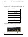
General Description
Specification
Output
Step
No. of output channel
Voltage
Output current
Light adjustment respond
time using button control
Input-to-output
respond
time
Input
Trigger output channel
Display
4-digit 7-segment display
Power supply Power rating
Current consumption
Lighting power supply
Control
Control method
Digital 256 steps (0-255)
4
12/24VDC
1A per channel
Within 420ms, at 24V
output
Within 50us, at 24V output
12V/24V
Colour: Red
7-35VDC
Approx. 44mA
12/24VDC
1.Display panel (Buttons)
2. Com Port (RS232)
3. USB
Power Input
The board power connectors should be connected to power supply of voltage 7-35 VDC
The lighting power can be supplied with 12/24V depend on the lighting power rating
Board Input Power
+7-35 VDC
Strobe Input
Lighting Input Voltages
Lighting Output
Page 3 of 29
V LIGHT
VL-LC-11-4CH-P1 LIGHTING CONTROLLER UNIT
Controller Mode
1. Constant Mode
2. Trigger Mode
3. Auto Strobe Mode
CONSTANT MODE
- 4 Output Channel (CH1 – CH4)
- The output is continuous current
- Range from 0 – 255
TRIGGER MODE
- 4 Inputs (IN1 – IN4)
- All 4 inputs have a same common of 24V (COM)
- Pull low trigger
- Output is pulsed once per trigger
- One input is used as a trigger (IN1 trigger CH1, IN2 trigger CH2, etc.)
- Pulse Width (0.1 – 999.9ms in 100us steps)
- The output intensity value in trigger mode is the intensity value in constant mode
- To use the trigger mode, set the desired constant value of the channel, then change to trigger
mode to set the pulse width.
AUTO STROBE MODE
- Output is pulsed continuously
- Up Time and Down Time (1 – 999ms in 1ms steps)
- The output intensity value in auto strobe mode is the intensity value in constant mode
- To use the auto strobe mode, set the desired constant value of the channel, then change to
auto strobe mode to set up time and down time.
The controller has a display panel consisting of a 4-digit seven segment display, four push
buttons and an LED indicator.
Page 4 of 29
V LIGHT
VL-LC-11-4CH-P1 LIGHTING CONTROLLER UNIT
Operation
The controller LC-11 can be controlled using either the display panel or external control
(RS232/USB). Both controls cannot be used at the same time.
The LED labeled “USB/RS232” is an indicator of which control is in use:
1. LED turned on – USB/RS232 control mode
2. LED turned off – Display Panel control mode
When the power is switched on, the controller is in the control mode last used on the LC-11
controller.
To switch the control, hold down UP and DOWN for about 1 second and observe the change
on the LED indicator.
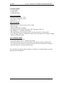
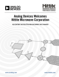
Display Panel Control Mode
In Display Panel Control Mode, user will control the controller by using the 4 Buttons at the
Front Panel (Set, Range, Up and Down) for setting Channel, Lighting intensity and trigger
pulse width.
USB/RS232
Control Mode LED
Button “SET” is
for set Parameter
Controller
Button “RANGE”
is for Moving Digit
for Setting Value
and for manually
test Trigger
Button “DOWN”
- Changing Mode(CONàTRIGàAUTO)
- Minus (-) Lighting Intensity, Trigger pulse
width Value, Up and Down Time
- Changing Channel (CH4àCH3àCH2àCH1)
Button “Up”
- Changing Mode(CONàTRIGàAUTO)
- Add (+) Lighting Intensity, Trigger pulse width
Value, Up and Down Time
- Changing Channel (CH1àCH2àCH3àCH4)
Front Panel
Page 5 of 29
V LIGHT
VL-LC-11-4CH-P1 LIGHTING CONTROLLER UNIT
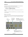
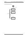
Setting up Constant and Trigger Operation using Display Panel
Idle State
Press and hold SET for about one second
Press RANGE
Use UP and DOWN to select the
current multiplier (1 to 10 which
equals to 10 – 100% of max current)
for all channels OR change board
address for cascade operation
Press SET
Press SET
Use UP and DOWN to select which
channel to set up (CH1 to CH4)
Press SET
Press SET
Press SET
Use UP and DOWN to select which
mode to use (CON or TRIG)
Press SET
Press SET
Use UP and DOWN to select the
required constant value (0 to 255) and
delay in milliseconds (0.0 to 9.9). The
delay is set up in multiples of 100us.
Minimum pulse width is 0.1ms, if user
set the value as 0, it will automatically
set it as 0.1ms.
Press SET
Press SET
The “units” digit is flashing. UP or
DOWN change the value by one.
Press RANGE to select the “tens” and
“hundreds” digits.
Back to Idle State
Page 6 of 29
V LIGHT
VL-LC-11-4CH-P1 LIGHTING CONTROLLER UNIT
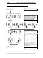
Auto Strobe Mode:
Press SET
Auto Strobe
Up Time
(with a dot
at last digit)
Press SET
Auto Strobe
Down Time
Press SET
Idle State
Remark:
Trigger operation can only work when the display is in Idle State.
During Trigger mode, the trigger function of the respective channel can be simulated using
the RANGE button. The channel is triggered once when the RANGE button is pressed. This
only works when the display is in IDLE mode.
During Auto Strobe mode, the auto strobe function for all channel can be turned ON or OFF
using the RANGE button. Only work for channel that is in AUTO mode.
Page 7 of 29
V LIGHT
VL-LC-11-4CH-P1 LIGHTING CONTROLLER UNIT
Setting up Board Address for Cascade Operation
Press and hold SET for about one second
Press RANGE
* Use UP and DOWN button to select board address
Board address must be set for controllers used in cascade operation.
Master controller is set as address 00
Slave controller can be set start from address 01
** REMARK: Address should be set to 00 if use as individual controller
Parameters in EEPROM
After the parameters have been set, they are saved into the controller’s EEPROM to retain
them after the power to the controller is turned off.
- To reset the parameters
The parameters in the memory can be reset to default values. To do this, first turn off the
power of the controller. Hold down the “SET” button while turning on the power, then let go
of the button.
Page 8 of 29
V LIGHT
VL-LC-11-4CH-P1 LIGHTING CONTROLLER UNIT
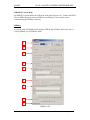
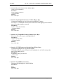
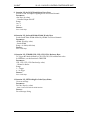
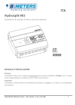
USB/RS232 Control Mode
In USB/RS232 Control Mode, the LED on the front panel will turn “On”. Connect the RS232
Cable or USB Cable (does not need USB Driver Installation). The controller can be
controlled using the LEDBasic Software.
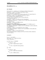
LEDBasic
1. Copy the folder LEDStudio which includes LEDLib and LEDBasic folder, into drive C:\
3. Run LEDBasic.exe in LEDBasic folder.
1
2
3
4
5
6
7
8
9
LEDBasic GUI
Page 9 of 29
V LIGHT
VL-LC-11-4CH-P1 LIGHTING CONTROLLER UNIT
Description
1. Connection
- Select the type of connection to be used - ComPort(RS232) or USB
- Select the port number where the controller is connected (Auto or 1-256)
- Connect/Disconnect
2. File
- Load previous configured parameters
- Save current parameters
- The configuration is saved as .ini file
3. Channel
- Select current multiplier for all channels (10%, 20%, … , 100% of max current)
- Select the channel to change the parameter
- Select board address for cascade operation
- Channel 1 to 4
4. Channel Mode
- Select mode for channel
- Constant Mode, Trigger Mode, Auto Strobe Mode
5. Parameter
- Change the light intensity (0-255)
- Turn light output ON and OFF
- Change pulse width (0-999.9ms)
6. Trigger Control
- Select the channel to trigger, also use for channel select in Auto Strobe mode
- Channel 1 to 4
- Trigger the selected channel(s)
7. Auto Strobe Control
- Change the Auto Strobe Up Time and Down Time (0-999ms)
- Channel 1 to 4
- Trigger the selected channel(s)
8. EEPROM
- Load parameters from EEPROM
- Save parameters into EEPROM
9. Connection Status
- Show the connection status
Page 10 of 29
V LIGHT
VL-LC-11-4CH-P1 LIGHTING CONTROLLER UNIT
LC-11 Cascade Operation
The LC-11 Lighting Controller can be used in cascade mode when there are more than 4
lighting output channel to be controlled at the same time.
The number of LC-11 controller can be connected in cascade is up to 16 where the address of
the controller is pre-set using the button control.
To use LC-11 in cascade,
- The address of the master controller must be set to 0 and communicate with the PC using
RS232 or USB
- The slave controller address can be set from 1 to 15 and is connected to the master
controller using RJ-10
Connection:
- Connect one side of the CAN Bus cable to any of the CAN BUS socket of the main LC-12
controller (address 00) and the other side to CAN BUS Socket of other slave controller
(address 01 – 15)
- To control more controllers, just connect them in loop
CAN BUS CONNECTOR
CAN BUS CABLE
Page 11 of 29
V LIGHT
VL-LC-11-4CH-P1 LIGHTING CONTROLLER UNIT
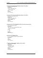
CAN BUS multi-drop connection:
PC
RS232 or USB
LC-11
Addr (0000)
LC-11
Addr (0001)
CAN BUS
LC-11
Addr (0015)
Page 12 of 29
V LIGHT
VL-LC-11-4CH-P1 LIGHTING CONTROLLER UNIT
Operation Description
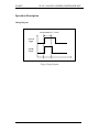
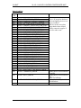
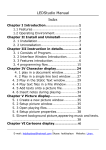
Timing Diagram
Strobe Width (0.1-9.9ms)
External
Trigger
Ligh ng
Output
Trigger Timing Diagram
Page 13 of 29
V LIGHT
VL-LC-11-4CH-P1 LIGHTING CONTROLLER UNIT
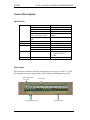
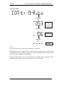
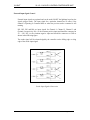
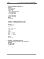
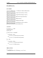
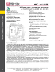
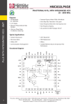
External Input Signal Control
External input signals are optional and can be used ON/OFF the lightings based on the
signals (trigger mode). The input signal for a particular channel has no effect if the
channel is operating in Constant Mode or when the previous strobe command is still
running.
IN1, IN2, IN3 and IN4 are input signals for Channel 1, Channel 2, Channel 3 and
Channel 4 respectively. IN(+) is the common positive input and should be connected to
5V – 24V, IN(-) is the common negative input and should be connector to GND as
shown in the following figure.
The strobe signal will be acknowledged by the controller on the falling edge or rising
edge of the strobe input signal.
Strobe Input Signals Connection
Page 14 of 29
V LIGHT
VL-LC-11-4CH-P1 LIGHTING CONTROLLER UNIT
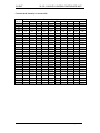
Constant mode intensity to current table
Intensity
0
10
20
30
40
50
60
70
80
90
100
110
120
130
140
150
160
170
180
190
200
210
220
230
240
250
255
10%
20%
30%
Current (mA) (Approximate)
40%
50%
60%
70%
80%
90%
100%
0
4
8
12
16
20
24
27
31
35
39
43
47
51
55
59
63
67
71
75
78
82
86
90
94
98
100
0
8
16
24
31
39
47
55
63
71
78
86
94
102
110
118
125
133
141
149
157
165
173
180
188
196
200
0
12
24
35
47
59
71
82
94
106
118
129
141
153
165
176
188
200
212
224
235
247
259
271
282
294
300
0
16
31
47
63
78
94
110
125
141
157
173
188
204
220
235
251
267
282
298
314
329
345
361
376
392
400
0
31
63
94
125
157
188
220
251
282
314
345
376
408
439
471
502
533
565
596
627
659
690
722
753
784
800
0
35
71
106
141
176
212
247
282
318
353
388
424
459
494
529
565
600
635
671
706
741
776
812
847
882
900
0
39
78
118
157
196
235
275
314
353
392
431
471
510
549
588
627
667
706
745
784
824
863
902
941
980
1000
0
20
39
59
78
98
118
137
157
176
196
216
235
255
275
294
314
333
353
373
392
412
431
451
471
490
500
0
24
47
71
94
118
141
165
188
212
235
259
282
306
329
353
376
400
424
447
471
494
518
541
565
588
600
0
27
55
82
110
137
165
192
220
247
275
302
329
357
384
412
439
467
494
522
549
576
604
631
659
686
700
Page 15 of 29
V LIGHT
VL-LC-11-4CH-P1 LIGHTING CONTROLLER UNIT
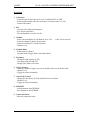
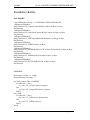
CABLE SELECTION
MODEL
POWER
LENGTH
APPLICATIONS
24V
1M
2M
3M
4M
5M
l Used to connect 24V light to USB /
RS232 / KL-4000 / STB / ANG-1CHP1 / LC-11 Series power supply
EXT-24V-F
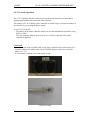
LIGHTING CONNECTORS
24V-Lighting Connector
Pin 1 -- Red wire (+ve)
Pin 3 -- White wire (-ve)
Page 16 of 29
V LIGHT
VL-LC-11-4CH-P1 LIGHTING CONTROLLER UNIT
LEDStudio DLL Documentation
Lighting Card
RS232 DLL
LED STUDIO DLL
Application
DLL Location Path
1. RS232 DLL must be located at C:\LEDStudio\LEDLib\RS232.dll
2. LEDStudio DLL must located at C:\LEDStudio\LEDLib\LEDStudio.dll
Function List
1. function LE_GetVersion(var Value: PChar): Byte; stdcall;
2. function LE_ComportConnect(var ComPort: Byte): Byte; stdcall;
3. function LE_ComportDisConnect(Comport: Byte): Byte; stdcall;
4. function LE_USBConnect(var ProductName: PChar): Byte; stdcall;
5. function LE_USBDisconnect: Byte; stdcall;
6. function LE_SetMultiplier(sMul: Byte): Byte; stdcall;
7. function LE_SetCHMode(sCH, sMode:Byte): Byte; stdcall;
8. function LE_SetConstInt(sInt: Byte): Byte; stdcall;
9. function LE_SetCONSTOnOff(sOn: Byte): Byte; stdcall;
10. function LE_SetStrobeWidth(sWidth: Word): Byte; stdcall;
11. function LE_STROBE(CH1, CH2, CH3, CH4: Boolean): Byte; stdcall;
12. function LE_GETErrMsg(ErrCode: Byte):Pchar ; stdcall;
13. function LE_SetAutoStrobeUpTime(UpTime: Word): Byte; stdcall;
14. function LE_SetAutoStrobeDnTime(DnTime: Word): Byte; stdcall;
15. function LE_AUTOSTROBE(CH1, CH2, CH3, CH4: Boolean): Byte; stdcall;
16. function LE_EEPROM: Byte; stdcall;
17. function LE_SelectAdd( sAdd:Byte): Byte; stdcall;
Page 17 of 29
V LIGHT
VL-LC-11-4CH-P1 LIGHTING CONTROLLER UNIT
1. function LE_GetVersion(var Value: PChar): Byte;
Get the version information.
Parameter:Value: String (by reference)
- Version number
Return:Error Code: Byte
2. function LE_ComportConnect(var ComPort: Byte): Byte;
Connect the lighting device via serial com port defined by 'Comport'
If Comport = 0, LEDStudio will auto detect and connect with Lighting device and will
return the comport number connected
Parameter:ComPort: Byte (by reference)
- Comport number
Return:Error Code: Byte
3. function LE_ComportDisConnect(Comport: Byte): Byte;
Disconnect the serial com port with lighting device
Parameter:Comport: Byte (by value)
- Comport number
Return:Error Code: Byte
4. function LE_USBConnect(var ProductName: PChar): Byte;
Connect the lighting device via USB port defined.
LEDStudio will auto connect USB port with Lighting device and will return product
name of the lighting device
Parameter:ProductName: String (by reference)
- Product Name
Return:Error Code: Byte
5. function LE_USBDisconnect: Byte;
Disconnect the lighting device from USB Port
Parameter:None
Return:Error Code: Byte
Page 18 of 29
V LIGHT
VL-LC-11-4CH-P1 LIGHTING CONTROLLER UNIT
6. function LE_SetMultiplier(sMul: Byte): Byte;
Set the current multiplier of lighting device
Parameter:sMul: Byte (by value)
- Current Multiplier
Range = 1 – 10
1 = 10% of Max Current (Default)
2 = 20% of Max Current
3 = 30% of Max Current
|
|
9 = 90% of Max Current
10 = 100% of Max Current
Return:Error Code: Byte
7. function LE_SetCHMode(sCH, sMode:Byte): Byte;
Set the mode of Channel defined by 'sCH' and 'sMode'.
Parameter:sCH: Byte (by value)
- Channel number
Range = 1 – 4
sMode: Byte (by value)
- Channel mode
Range =
LEDBasic:
Mode = 0 => Constant
Mode = 1 => Trigger
Mode = 3 => Auto Strobe
Return:Error Code: Byte
8. function LE_SetConstInt(sInt: Byte): Byte;
Set the Constant Intensity defined by ‘sInt’ for selected channel
Parameter:sInt: Byte (by value)
- Constant Intensity
Range = 0-255
Return:Error Code: Byte
Page 19 of 29
V LIGHT
VL-LC-11-4CH-P1 LIGHTING CONTROLLER UNIT
9. function LE_SetCONSTOnOff(sOn: Byte): Byte;
Set ON or OFF for output of lighting device for selected channel
Parameter:sOn: Byte (by value)
- Constant Output ON/OFF
Range:
On = 1
Off = 0
Return:Error Code: Byte
10. function LE_SetStrobeWidth(sWidth: Word): Byte;
Set the Strobe Pulse Width defined by 'sWidth' for selected channel.
Parameter:sWidth: Word (by value)
- Strobe Width
Range = 0-9999(0-999.9ms)
Return:Error Code: Byte
11. function LE_STROBE(CH1, CH2, CH3, CH4: Boolean): Byte;
To Trigger the Strobe defined by CH1,CH2,CH3,CH4 with boolean value
In LEDBasic, use this function to TRIGGER
Parameter:CH1, CH2, CH3, CH4: Boolean (by value)
- Channel to Strobe
Range:
1 = Trigger
0 = No trigger
Return:Error Code: Byte
12. function LE_GETErrMsg(ErrCode: Byte):Pchar ;
Get error message
Parameter:ErrCode: Byte (by value)
- Error Code retrieved from called function
Return:Error Message: String
Page 20 of 29
V LIGHT
VL-LC-11-4CH-P1 LIGHTING CONTROLLER UNIT
13. function LE_SetAutoStrobeUpTime(UpTime: Word): Byte;
Set the auto strobe Up Time
Parameter:UpTime: Word (by value)
- Autostrobe On Time
Range = 1-999ms
Return:Error Code: Byte
14. function LE_SetAutoStrobeDnTime(DnTime: Word): Byte;
Set the auto strobe Down Time
Parameter:DnTime: Word (by value)
- Autostrobe Off Time
Range = 1-999ms
Return:Error Code: Byte
15. function LE_AUTOSTROBE(CH1, CH2, CH3, CH4: Boolean): Byte;
Turn On/Off the auto strobe
Parameter:CH1, CH2, CH3, CH4: Boolean (by value)
- Channel to Autostrobe
Range =
1 = On
0 = Off
Return:Error Code: Byte
16. function LE_EEPROM: Byte;
To save lighting parameters into the EEPROM
Parameter:None
Return:Error Code: Byte
17. function LE_SelectAdd( sAdd:Byte): Byte; stdcall;
Select controller address
Parameter:sAdd: Byte (by value)
- Controller address
Range = 0-15
Return:Error Code: Byte
Page 21 of 29
V LIGHT
VL-LC-11-4CH-P1 LIGHTING CONTROLLER UNIT
Error Code List
Error
Code
0
100
105
106
107
110
115
116
120
122
123
124
130
131
132
135
140
145
150
155
160
165
170
195
196
200
201
202
203
242
Desciption
Success No Error Excute
'Err100 - GET_VERSION_ERROR'
'Err105 - COMPORT_CONNECT_ERROR'
'Err106 - NO_COM_DEVICE_DETECTED'
'Err107 - CONNECT_SELECTED_COM_FAIL'
'Err110 - COMPORT_DISCONNECT_ERROR'
'Err115 - USB_CONNECT_ERROR'
'Err116 - NO_USB_DEVICE_DETECTED'
'Err120 - USB_DISCONNECT_ERROR'
‘Err122 - TCPIP_CONNECT_ERROR’
‘Err123 - NO_TCPIP_DEVICE_DETECTED’
‘Err123 - TCPIP_DISCONNECT_ERROR'
'Err130 - SET_CHMODE_ERROR';
'Err131 - INVAILID_CH_NUMBER'
'Err132 - INVAILID_MODE_NUMBER'
'Err135 - SET_MULTIPIER_ERROR'
'Err140 - SET_CONST_INT_ERROR'
'Err145 - SET_CONST_ONOFF_ERROR'
'Err150 - SET_STROBE_INT_ERROR'
'Err155 - SET_STROBE_DELAY_ERROR'
'Err160 - SET_STROBE_WIDTH_ERROR'
'Err165 - SET_STROBE_ODELAY_ERROR'
'Err170 - LE_STROBE_ERROR'
'Err195 - SET_INTENSITY_BANK_ERROR'
'Err196 - BANK_STROBE_ERROR'
'Err200 - SEND_MSG_ERROR'
'Err201 - WRITE_MSG_ERROR'
'Err202 - READ_MSG_ERROR'
'Err203 - READ_MSG_CHECKSUM_ERROR'
'Err242 - COMMAND_ERROR'
248
'Err248 - DATA_ERROR'
255
'Err255 - COMMUNICATION_ERROR'
Ensure all integration hardware,
cable and lighting device are in
proper condition.
And also in the correct data
range that has been defined.
Kindly contact the supplier if
the error codes occur.
lighting device received invalid
command
lighting device received invalid
data
(Data Not In Range)
lighting device verify invalid
checksum data
Page 22 of 29
V LIGHT
VL-LC-11-4CH-P1 LIGHTING CONTROLLER UNIT
EXAMPLE (C#):
DLL IMPORT:
const string LEDStudiodll = "C:\\LEDStudio\\LEDLib\\LEDStudio.dll";
[DllImport(LEDStudiodll)]
public static extern byte LE_ComportConnect(ref byte ComPort);
[DllImport(LEDStudiodll)]
public static extern byte LE_ComportDisConnect(byte Comport);
[DllImport(LEDStudiodll)]
public static extern byte LE_USBConnect(string ProductName);
[DllImport(LEDStudiodll)]
public static extern byte LE_USBDisconnect();
[DllImport(LEDStudiodll)]
public static extern byte LE_SetMultipier(byte sMul);
[DllImport(LEDStudiodll)]
public static extern byte LE_SetCHMode(byte sCH, byte sMode);
[DllImport(LEDStudiodll)]
public static extern byte LE_SetConstInt(byte sInt);
CONNECT:
byte portnum = 1; // COM1
string productname;
byte err_code;
if (COM_Connect) // COMPORT
{
if (connected == false)
err_code = LE_ComportConnect(ref portnum);
else
err_code = LE_ComportDisConnect(portnum);
}
else // USB
{
if (connected == false)
err_code = LE_USBConnect(productname);
else
err_code = LE_USBDisconnect();
}
ERROR CHECK:
if (err_code != 0)
MessageBox.Show(LE_GETErrMsg(err_code), "Error");
Page 23 of 29
V LIGHT
VL-LC-11-4CH-P1 LIGHTING CONTROLLER UNIT
SET MULTIPLIER:
byte multiplier = 5; // 50%
err_code = LE_SetMultipier(multiplier);
SET CHANNEL & MODE:
byte channel = 1; // Channel 1
byte channel_mode = 0; // Constant mode
err_code = LE_SetCHMode(channel, channel_mode);
CONSTANT:
byte const_int = 100; // Intensity 100
err_code = LE_SetConstInt(const_int);
byte on_off = 1; // On
err_code = LE_SetCONSTOnOff (on_off);
STROBE/TRIGGER:
UInt16 strobe_width = 1000; // 1ms strobe width
err_code = LE_SetStrobeWidth(strobe_width);
err_code = LE_STROBE(true, false, false, false) // strobe channel 1
AUTO STROBE:
UInt16 auto_uptime = 250; // 250ms up time
UInt16 auto_dntime = 400; // 400ms down time
err_code = LE_SetAutoStrobeUpTime(auto_uptime)
err_code = LE_SetAutoStrobeDnTime(auto_dntime)
err_code = LE_AUTOSTROBE(true, false, false, false) // turn on channel 1 auto strobe (set
false = turn off)
SAVE PARAMTERS IN EEPROM:
err_code = LE_EEPROM();
Page 24 of 29
V LIGHT
VL-LC-11-4CH-P1 LIGHTING CONTROLLER UNIT
EXAMPLE (VC++):
DLL IMPORT:
HINSTANCE lib = LoadLibraryA("C:\\LEDStudio\\LEDLib\\LEDStudio.dll");
typedef byte (__stdcall * LE_ComportConnect)(int& ComPort);
LE_ComportConnect ComportConnect =
reinterpret_cast<LE_ComportConnect>(GetProcAddress(lib, "LE_ComportConnect"));
typedef byte (__stdcall * LE_ComportDisConnect)(byte ComPort);
LE_ComportDisConnect ComportDisConnect =
reinterpret_cast<LE_ComportDisConnect>(GetProcAddress(lib,
"LE_ComportDisConnect"));
typedef byte (__stdcall * LE_USBConnect)(char* ProductName);
LE_USBConnect USBConnect = reinterpret_cast<LE_USBConnect>(GetProcAddress(lib,
"LE_USBConnect"));
typedef byte (__stdcall * LE_USBDisconnect)();
LE_USBDisconnect USBDisconnect =
reinterpret_cast<LE_USBDisconnect>(GetProcAddress(lib, "LE_USBDisconnect"));
typedef byte (__stdcall * LE_SetMultiplier)(byte sMul);
LE_SetMultiplier SetMultiplier = reinterpret_cast<LE_SetMultiplier>(GetProcAddress(lib,
"LE_SetMultiplier"));
typedef byte (__stdcall * LE_SetCHMode)(int sCH, int sMode);
LE_SetCHMode SetCHMode = reinterpret_cast<LE_SetCHMode>(GetProcAddress(lib,
"LE_SetCHMode"));
typedef byte (__stdcall * LE_SetConstInt)(int sInt);
LE_SetConstInt SetConstInt = reinterpret_cast<LE_SetConstInt>(GetProcAddress(lib,
"LE_SetConstInt"));
CONNECT:
int cp = 1; // port number
int& comport = cp; // variable by reference
String ^productname = "";
if (COM_Connect) // COMPORT
{
if (connected == false)
err_code = ComportConnect(comport);
else
err_code = ComportDisConnect(portnum);
}
else // USB
{
if (connected == false)
err_code = USBConnect(productname);
else
err_code = USBDisconnect();
}
Page 25 of 29
V LIGHT
VL-LC-11-4CH-P1 LIGHTING CONTROLLER UNIT
ERROR CHECK:
String ^err_msg;
if (err_code != 0) err_msg = GETErrMsg(err_code);
SET MULTIPLIER:
byte multiplier = 5;
err_code = SetMultiplier(multiplier);
SET CHANNEL & MODE:
int channel = 1; // CH1
int mode = 0; // constant mode
err_code = SetCHMode(channel, mode);
CONSTANT:
byte intensity = 100;
err_code = SetConstInt(intensity);
byte on_off = 1; // On
err_code = SetCONSTOnOff (on_off);
STROBE/TRIGGER:
short strobe_width = 1000; // 1ms strobe width
err_code = SetStrobeWidth(strobe_width);
err_code = STROBE(true, false, false, false); // strobe channel 1
AUTO STROBE:
short auto_uptime = 250; // 250ms up time
short auto_dntime = 400; // 400ms down time
err_code = SetAutoStrobeUpTime(auto_uptime);
err_code = SetAutoStrobeDnTime(auto_dntime);
err_code = AUTOSTROBE(true, false, false, false); // turn on channel 1 auto strobe (set false
= turn off)
SAVE PARAMTERS IN EEPROM:
err_code = EEPROM();
Page 26 of 29
V LIGHT
VL-LC-11-4CH-P1 LIGHTING CONTROLLER UNIT
EXAMPLE (VB.NET):
DLL IMPORT:
Const LEDStudio As String = "C:\LEDStudio\LEDLib\LEDStudio.dll"
<DllImport(LEDStudio)> _
Public Function LE_ComportConnect(ByRef ComPort As Byte) As Byte
End Function
<DllImport(LEDStudio)> _
Public Function LE_ComportDisConnect(ByVal Comport As Byte) As Byte
End Function
<DllImport(LEDStudio)> _
Public Function LE_USBConnect(ByRef ProductName As String) As Byte
End Function
<DllImport(LEDStudio)> _
Public Function LE_USBDisconnect() As Byte
End Function
<DllImport(LEDStudio)> _
Public Function LE_SetCHMode(ByVal sCH As Byte, ByVal sMode As Byte) As Byte
End Function
<DllImport(LEDStudio)> _
Public Function LE_SetMultipier(ByVal sMul As Byte) As Byte
End Function
<DllImport(LEDStudio)> _
Public Function LE_SetConstInt(ByVal sInt As Byte) As Byte
End Function
CONNECT:
Dim comport As Byte = 1 ‘COM1
Dim productname As String = ""
If (COM_Connect) Then ‘COMPORT
If (connected == false)
err_code = LE_ComportConnect (comport)
Else
err_code = LE_ComportDisConnect (comport)
End If
Else ‘USB
If (connected == false)
err_code = LE_USBConnect (productname)
Else
err_code = LE_USBDisconnect ()
End If
End If
Page 27 of 29
V LIGHT
VL-LC-11-4CH-P1 LIGHTING CONTROLLER UNIT
ERROR CHECK:
Dim err_msg As String
If Not err_code = 0 Then
err_msg = LE_GETErrMsg(err_code)
SET MULTIPLIER:
Dim multiplier As Byte = 5 ‘50% of max current
err_code = LE_SetMultiplier(multiplier)
SET CHANNEL & MODE:
Dim channel As Integer = 1 ‘CH1
Dim mode As Integer = 0 ‘constant mode
err_code = LE_SetCHMode(channel, mode)
CONSTANT:
Dim intensity as Byte = 100
err_code = LE_SetConstInt(intensity)
Dim on_off As Byte = 1 ‘On
err_code = LE_SetCONSTOnOff (on_off)
STROBE/TRIGGER:
Dim strobe_width as Short = 1000 ‘1ms strobe width
err_code = LE_SetStrobeWidth(strobe_width)
err_code = LE_STROBE(true, false, false, false) ‘strobe channel 1
AUTO STROBE:
Dim auto_uptime As Short = 250 ‘250ms up time
Dim auto_dntime As Short = 400 ‘400ms down time
err_code = LE_SetAutoStrobeUpTime(auto_uptime)
err_code = LE_SetAutoStrobeDnTime(auto_dntime)
err_code = LE_AUTOSTROBE(true, false, false, false) ‘turn on channel 1 auto strobe (set
false = turn off)
SAVE PARAMTERS IN EEPROM:
err_code = LE_EEPROM()
Page 28 of 29