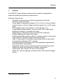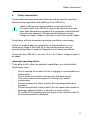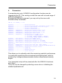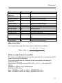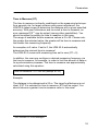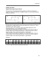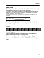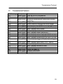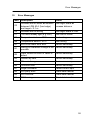
1
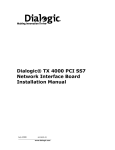
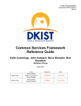
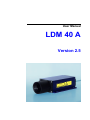
User Manual LDM 40 A Version 2.5 Dear User You are advised to read this User Manual carefully before you start using the LDM 40 A laser distance measurement module. This is necessary to ensure that you will be able to utilise all the capabilities which your new acquisition provides. This technology is subject to continuously ongoing development. Editorial deadline: August 2004 Manual Version: V 2.5 LDM 40 A Firmware Version: V1.04 NOTE Appropriate care was used in compiling this document. No liability will be accepted in the event of damage resulting from a non-compliance of the information that is contained herein. Table of Contents Table of Contents 1. General ..........................................................................................4 2. Safety Instructions .......................................................................5 3. Performance Data.........................................................................7 4. Working Principle.........................................................................9 5. Setup ...........................................................................................10 6. Interface Cable Wire Assignments ...........................................12 Shield and Grounding..............................................................13 Termination of RS 232 ............................................................13 7. Limiting Values for Voltages.....................................................14 8. Starting Up ..................................................................................15 9. Parameters..................................................................................16 10. Functions ....................................................................................22 Command for Distance Measurement ....................................22 Output and Input......................................................................23 11. Transmission Protocol ..............................................................25 12. Error Messages ..........................................................................26 13. PC Interface Cable (Option) ......................................................27 13. Service and Maintenance ..........................................................28 3 General 1. General The LDM 40 A laser distance measurement module is designed for mobile and stationary distance measurement. Particular features are: Operation under extreme outdoor temperatures with high accuracy and great reach Great range of operating voltages (10 V= to 30 V=) from on-board vehicle supply, a direct voltage industrial supply net or a DC power pack Small stable power consumption <1.5 W (without IAlarm) Long distance measurement, and more than 100 m reach with 1 additional reflectors mounted onto target (depending on reflectance and environmental conditions) Simple sighting with visible laser beam Flexible extendible interface cable for voltage supply, bi-directional data interface, switching output and analog output Input of commands for available measuring functions and output of measured readings via PC or laptop Switching output and analog output are separately programmed and with different parameters Adjustable distance barrier with hysteresis sets switching output Measured values are displayed in meters, decimetres, centimetres, feet, inches, etc. due to free scaling Option for remote triggering of measurement from external trigger device 1 3M, Type 3270, 3290, 5290 4 Safety Instructions 2. Safety Instructions These safety and operating instructions should be carefully read and followed during operation and handling of the LDM 40 A. There is danger from laser radiation or electrical shock! For repair work, the LDM 40 A may not be opened by anyone other than Manufacturer personnel or expressly authorised and duly instructed persons. Please note that dangerous high voltage and laser radiation is present in the inner product space. Compliance with the prescribed operating conditions is necessary. Failure to observe advice or information contained herein or nonconforming usage of the LDM 40 A may cause physical injury to operating personnel or material damage to the measuring module. To operate the LDM 40 A, use only 10 V to 30 V direct voltage supply in all cases. Important operating advice To be able to fully utilise the system's capabilities, you should strictly follow these rules: - Do not operate the module if there is fogging or contamination on optical parts. Do not touch the module's optical parts with bare hands. Use caution when removing dust or soiling from optical components. Prevent exposure to shock impacts during transportation and operation. Prevent overheating of the module. Do not expose the module to direct sun radiation while it is stored in a motor vehicle. The LDM 40 A is splashproof and dustproof as required under IP 65 internal protection standards. 5 Safety Instructions - The LDM 40 A laser distance measurement module is a class 2 laser product under DIN EN 60825-1:2001-11. Warning: There is class 2 laser radiation when the cover is removed. Do not look into the beam! Performance Data 3. Performance Data 2 Measuring range : 0.2 m up to 30 m with natural surfaces, more than 100 m achievable depending on target reflectance Measuring accuracy : ± 2 mm under defined measuring conditions4, ± 3 mm (+15 °C up to +30 °C), ± 5 mm (-10 °C up to +50 °C) Meas. value resolution: 0.1 mm, user scalable 3 ± 0.5 mm 5 Repeatability : Measuring time: 0.16 up to 6 s or 0.1 s (10 Hz) on white surface 6 Laser divergence : 0.6 mrad Operating temperature: - 10 °C to + 50 °C Storage temperature: - 20 °C to + 70 °C Shock resistance: 10 g / 6 ms persistence shock DIN ISO 9022-3-31-01-1 Supply voltage: 10 V to 30 V direct voltage Power consumption: depending on operating mode < 0.4 W for standby, < 1,5 W for distance tracking 7 Data interface : RS 232/RS 422, baud rate: 2400 to 38400, format: 8N1 (fixed) Digital switching output: programmable switching threshold and hysteresis, "high-side switch", rated for max. load of 0.5 A 2 dependent on target reflectance, steady light influences and atmospheric conditions typical measuring accuracy under average conditions within specified measuring range you should consult the Manufacturer or your local distributor! 5 dependent on target reflectance, steady light influences and atmospheric conditions 6 at 10 m distance the beam diameter is 6 mm, at a distance of 100 m it is 6 cm 7 convertible, conversion to be carried out by certified personnel 3 4 7 Performance Data Analog output: 4 mA to 20 mA current output, programmable distance range limits, load resistance ≤ 500 Ω, accuracy: ± 0.15%, Temperature drift: < 50 PPM/°C Trigger input: external triggering, 5 V pulse height, trigger flank adjustable, trigger delay adjustable Eye safety class: laser class 2 under DIN EN 60825-1:2001-11 Wavelength: 650 nm (visible) Dimensions (L x W x H): 182 mm x 96 mm x 50 mm Weight: 850 g Internal protection class: IP 65 Working Principle 4. Working Principle The LDM 40 A works based on comparative phase measurement. To achieve this, it emits visible laser beams in different frequencies. The target being measured returns diffusely reflected light that is subsequently compared with a reference signal. Finally, a microprocessor uses the recorded phase shift to calculate a required distance with mm accuracy. Figure 1 Working principle A distance measurement can be triggered in different ways: manually at the PC with terminal program automatically after parameterisation of Autostart command continuously by selecting distance tracking mode remotely controlled with external triggering For a description of these trigger options, refer to à sections 9 "Parameters" and à 10 "Functions" of this Manual. 9 Setup 5. Setup The laser distance measurement module is shipped together with an interface cable (about 2 m in length) and a User Manual in a padded cardboard box which can also be used for safe transportation of the LDM 40 A. Figure 2 Technical drawing 1 2 3 4 5 6 7 Tube at front cover Casing Gland seal for interface cable in back cover Receiver optics Transmitter optics Holes for mechanical attachment (four) Interface cable 10 Setup The casing consists of a robust, non-corroding continuously cast aluminum part with front and back cover, also non-corroding. The base plate contains four holes for mechanical attachment of the LDM 40 A. To protect the optical components from dust, physical contact, mechanical impacts, etc., a choke is fixed to the casing. Depending on the customer's request, the LDM 40 A may be shipped with a tube of any 8 greater length or with no tube at all . In the event of unqualified tube removal, measurement can no more be warranted to function correctly! The back cover contains a gland seal port for the interface cable (2 m in length) as required by IP 65 standards. Where local conditions necessitate a greater distance between the actual measuring location and the PLC / PC / voltage supply, the 9 interface cable can be extended with a extra shielded cable . 8 9 please get in touch with your contact person! may deviate from interfacing specifications! Interface Cable Wire Assignments 6. Interface Cable Wire Assignments Caution: The cable ends are uncovered! It's the user's responsibility to prevent shorts! The cable shield must be grounded with low resistance. Interface cable wiring assignments are as follows: Figure 3 Interface cable colour codes No. Designation Function if RS 232 1 Colour code white ALARM 2 green TxD / RX+ Digital switching output RS 232 send data 3 yellow RxD / RX- 4 5 grey brown GND TRIG 6 orange or pink blue red black violet VCC Digital switching output RS 422 receive data + RS 232 receive data RS 422 receive data Ground potential Ground potential External External synchronisation synchronisation Supply voltage Supply voltage GND IOUT TXTX+ Ground potential Current output RS 422 send data RS 422 send data + 7 8 9 10 Function if RS 422 Ground potential Current output RS 422 send data RS 422 send data + 12 Interface Cable Wire Assignments The GND wires are internally combined to serve as reference potential for all voltage values specified below. If data transfers are accomplished via RS 232, we recommend using cable 4 (grey, GND) as signal ground and cable 7 (blue, GND) as supply ground! The limiting values for voltages, load rates and logic levels are identical with those specified for RS 232 or RS 422 operation. All outputs are sustained-short-circuit-proof. Shield and Grounding The cable shield must be grounded with low resistance. For cable extension use only high quality shielded cable. Carrier base and control box should be have the same potential. Potential differences are reason for electrical current and can cause EMC problems (no correct measurement function or “hang” of the gauge). Is no potential equalization possible, mount the LDM 40 A isolated from the carrier base (use Nylon screwing and washers). Termination of RS 232 (if not in use or with open terminal points) 2 green 3kΩ 3 yellow 4 gray LDM 40 A Make sure you leave no data line end open. It will be highly sensitive to 2.2nF interferences (EMC). A terminator circuit should be installed when the RS 232 is unconnected. This circuit must be provided by the customer (see diagram on the left). Please keep the RS 232 norm. The maximal cable length of the RS 232 is 15 m. Use alternatively a RS 422 connection (use shielded twisted pair cable, maximum 300 m, termination resistor 100 Ω). 13 Limiting Values for Voltages 7. Limiting Values for Voltages Input voltages: Terminal point VCC TxD RxD TX+ TXRX+ RXTRIG Voltage 30 V ± 13.2 V ± 25 V ± 14 V ± 14 V ± 14 V ± 14 V ± 25 V Comment pole-reversal-protected short-circuit-proof short-circuit-proof short-circuit-proof short-circuit-proof short-circuit-proof short-circuit-proof short-circuit-proof Voltage ± 5.4 V ≥2V ≥ VCC – 2 V Comment ± 5 V at 3 kΩ load differentially at 2 x 50 Ω load level depending on VCC Output voltages: Terminal point TxD TX+, TXAlarm All outputs are sustained-short-circuit-proof. Caution: Do not connect the current output IOUT to the power supply (10 .. 30 V). This will destroy the interface board! 14 Starting Up 8. Starting Up Protect all cable ends against short-circuit effects before you turn voltage supply on! Necessary cable connections must be established in accordance with table specifications on the previous page. You require a PC with corresponding data interface port and a terminal program to perform start-up of the LDM 40 A. For starting up, the LDM 40 A needs to be installed at the measuring site, aligned until pointing to a desired target, and kept stable in this position. The target should preferentially have a homogeneous white surface. Caution: Do not use any retro reflectors! 10 Alignment of the LDM 40 A is facilitated by a laser beam that is visible and can easily be turned on at the PC. Operating voltage supply must be connected to the corresponding ends of the interface cable. A pole-reversal protection is integrated to prevent the destruction of electronic components. 10 depending on ambient light and target conditions 15 Parameters 9. Parameters A comprehensive set of LDM 40 A configuration functions can be triggered at the PC. This variety provides the user with a broad range of potential applications. By selecting ID[Enter] command, you may call up the menu with available setup commands. LDM 40, s/n xxxxxx, V 1.04 DT[Enter]..................distancetracking DW[Enter]..................distancetracking with cooperetive target (10Hz) DF[Enter]..................distance measurement with ext.trigger DM[Enter]..................distance measurement TP[Enter]..................internal temperature [C] SA[Enter] / SAxx[Enter]....display/set average value [1..20] SD[Enter] / SDxx[Enter]....display/set display format [d/h] ST[Enter] / STxx[Enter]....display/set measure time [0..25] SF[Enter] / SFx.x[Enter]...display/set scale factor SE[Enter] / SEx[Enter].....display/set error mode [0/1/2] 0..Iout=const., ALARM=const. 1..Iout=4mA, ALARM: OFF@AH>0, ON@AH<0 2..Iout=20mA, ALARM: ON@AH>0, OFF@AH<0 AC[Enter] / ACx.x[Enter]...display/set ALARM center AH[Enter] / AHx.x[Enter]...display/set ALARM hysterese RB[Enter] / RBx.x[Enter]...display/set distance of Iout=4mA RE[Enter] / REx.x[Enter]...display/set distance of Iout=20mA TD[Enter] / TDxx x[Enter]..display/set trigger delay [0..9999ms] trigger level [0/1] BR[Enter] / BRxxxx[Enter]..display/set baud rate [2400..38400] AS[Enter] / ASdd[Enter]....display/set autostart command [DT/DW/DF/DM/TP/LO] OF[Enter] / OFx.x[Enter]...display/set distance offset LO[Enter]..................laser on LF[Enter]..................laser off PA[Enter]..................display settings PR[Enter]..................reset settings This allows you to optimally match the measuring module's performance to a particular measuring site environment and sighting task, which is achieved by intelligent parameterisation before measurement actually begins. Your parameter setup will be preserved after the LDM 40 A has been shut down! They can only be changed by selecting a new value or initialising the standard parameter set. 16 Parameters Parameter Distance tracking Mean value Output format Time to measure Scale factor Alarm centre Alarm hysteresis Range Begin Range End Trigger delay Baud rate Autostart Abbreviation DW Relevance Distance measurement SA SD ST Distance measurement Distance measurement Distance measurement SF AC AH RB RE TD BR AS Distance measurement Digital switching output Digital switching output Analog output Analog output External triggering All serial communications Behaviour on turning the LDM 40 A on Distance measurement Distance measurement Distance offset Error Mode OF SE Mean Value (SA) For a specified range, the mean value is obtained as follows: x1 + x2 + x3 + ... + xn (20) Mean value x = n Distance Value Output Format (SD) For output of measured distance values, decimal (D) or hexadecimal (H) output mode can be selected. The output mode has an influence on all commands that display a distance value. Hex format: <SPACE>xxxxxx<CR><LF>, x=0...F, 1 mm resolution (SF1), Negative numbers: two's complement, Error: Exx<CR><LF>, Dist.: 34.56789...m, SF 1, output: _008708<CR><LF> Dist.: 34.56789...m, SF10, output:_05464F<CR><LF> 17 Parameters Time to Measure (ST) The time to measure is directly conditional on the measuring technique. As a general rule: for target surfaces with poorer reflectance, the LDM 40 A takes longer to determine the distance with a given specified accuracy. With poor reflectance and too small a time to measure, an 11 error message E15 may be output (among other possibilities). You should increase the setting for time to measure in this case. The range of available time-to-measure values is 0 to 25. Please note: the greater the selected value, the greater will be time to measure and the smaller the measuring frequency. An exception is 0 value. If set to 0, the LDM 40 A automatically determines the minimal time to measure! The LDM 40 A comes with measuring time set to zero (ST = 0). In addition, the user may configure a desired measuring frequency via the time to measure, for example, in order to limit the amount of data or for synchronisation purposes. The time to measure can approximately calculated using this equation: Time to measure ≈ ST⋅240 ms (except ST=0) Example: The distance to be determined is 25 m. The target's reflectance is not ideal. If ST 2 is selected for time to measure, E15 will be output. You should choose a greater time-to-measure value in this case! 11 see à section 12.“Error Messages“ 18 Parameters Scale Factor (SF) The scale factor multiplies a calculated distance value with a userselectable factor to change resolution or to switch the output to a different unit of measure. The scale factor setting has an influence on the output of the measured value, the distance offset (OF), the Alarm Centre (AC), the Alarm Hysteresis (AH), the Range Beginning (RB) and the Range End (RE)! Resolution 1 mm 0.1 mm 0.01 Yard 0.01 feet 1 inch Numerical measure 134.567 1345.671 147.162 441.493 52.979 Unit of measure m dm yard feet 100 inches Scale factor SF1 SF10 SF1.0936 SF3.28084 SF0.3937 Alarm Centre (AC) Alarm Centre corresponds to the distance threshold of the switching output. Alarm Centre is input in meters. On negative or positive excession of the pre-set switching threshold, the alarm output will switch from „High“ to „Low“ or vice versa depending on the alarm hysteresis setting. „High“ corresponds to about VCC – 1 V, „Low“ to 0 V. Alarm Hysteresis (AH) Alarm Hysteresis defines the response hysteresis of the switching output. Alarm Hysteresis settings are made in units of a meter. The value of a hysteresis setting corresponds to the delay in switching (in m), its mathematical sign describes the logic level. Range Beginning (RB) Range Beginning corresponds to the lower range limit of the analog output. Range Beginning settings are made in units of a meter. Range Beginning corresponds to a current of 4 mA. The value of RB must be lower then RE! 19 Parameters Range End (RE) Range End corresponds to the upper distance limit of the analog output. Range End settings are made in units of a meter. Range End corresponds to a current of 20 mA. The value of RE must be greater then RB! Caution: When setting the parameters RB and RE one must follow the rule that RB < RE. In any other case the state of the analog output will be in an undefined state! Trigger Delay (TD) Trigger Delay consists of two sub-parameters – the actual delay, i.e. the waiting time, and the trigger level. Delay corresponds to the time from the point when a trigger signal is received to the moment at which a measured value is output. It may take on a maximum value of 9999 ms. The trigger level allows you to define if measurement is to be triggered at a low-high flank (0) or a high-low flank (1). Your selections for trigger delay and trigger level must be separated by space (20h) (see à 11. "Transmission Protocol")! Baud Rate (BR) For baud rate, the following settings are available: 2400, 4800, 9600, 19200, 38400. Faulty inputs are automatically rounded to the nearest available baud rate. The data format is fixed. It includes eight data bits, no parity and one stop bit. Autostart (AS) Allows you to define a function which the LDM 40 A is to carry out when voltage supply becomes available. Possible inputs are: Any function that outputs a measured value and ID command. For example, if ASDT has been parameterised, the LDM 40 A will start with distance tracking immediately after power is available. 20 Parameters Distance Offset (OF) With the help of this parameter the user may conveniently define a zero point of his/her measuring setup. Receiver optics Figure 4 Front edge of LDM 40 A Zero point of the LDM 40 A (OF = 0.000000e+00) coincides with the front edge of the receiving lens. Error Mode (SE) SE (error mode) allows you to configure the behaviour of the digital switching output (alarm) and/or the analog output following an error message (E15, E16, E17). Depending on the particular LDM 40 application environment, error messages have to be handled in different ways. While errors must be detected in some applications, they may be ignored in others. In order to provides an error management option for users, an SE parameter (error mode) has been implemented in firmware version 1.04 (and following). Available setting options are 0, 1 and 2 with the following effects in the case of an error: SE Digital switching output 0 1 2 Hold voltage level of latest valid measurement Positive alarm hysteresis = LOW Negative alarm hysteresis = HIGH Positive alarm hysteresis = HIGH Negative alarm hysteresis = LOW Analog output Outputs current of latest valid measurement Output current value = 4 mA Output current value = 20 mA 21 Functions 10. Functions Command for Distance Measurement Function Distance Measurement Distance Tracking Distance Tracking for White Target Distance Tracking with Trigger Command Meaning DM single distance measurement DT DW DF continuous distance measurement continuous distance measurement 10 Hz continuous distance measurement with trigger synchronisation Please use this command for the Autostart Command (e.g. ASDT). Distance Measurement (DM) Starts a single distance measurement. Distance Tracking (DT) Starts the continuous distance measurement (rate see parameter “ST”). ESC stops the measurement. Distance Tracking for White Target (DW) For a constant measuring rate of 10 Hz, a white target board must be affixed to the target. ESC stops the measurement. Distance Tracking with Trigger (DF) Starts the continuous distance measurement mode. The beginning of every measurement is synchronously to the input TRIG (see à Parameter “Trigger delay TD“). ESC stops the measurement. 22 Functions Output and Input Digital Switching Output (Alarm) The purpose of the digital switching output is to allow monitoring of targets or scenes for positive or negative edge of a user parametrizable distance threshold. Figure 5 Alarm hysteresis, positive Figure 6 Alarm hysteresis, negative Configuration is performed by choosing appropriate settings for "Alarm Hysteresis" and "Alarm Centre". The logic state of the switching output essentially depends on the mathematical sign of your hysteresis setting. If the setting for hysteresis is positive, the output will switch to high on positive edge of the switching threshold + hysteresis/2 and to low on negative edge of the switching threshold - hysteresis/2. If the setting for hysteresis is negative, the output will switch to low on positive edge of the switching threshold + hysteresis/2 and to high on negative edge of the switching threshold - hysteresis/2. Example: AC 1m 1m AH 0.2m - 0.2 m (+) 0.8 m L H 0.9 m L H 1.0 m L H 1.1 m H L 1.2 m H L 1.1 m H L 1.0 m H L 0.9 m H L 0.8 m L H L = low, H = high, with distance increasing from left to right 23 Functions Analog Output The analog output allows a standardised long-distance transmission of analog distance data with the help of a two-wire cable. The level of current which is output to this cable is proportional to the measured distance value within a distance interval that is defined by "Range Beginning" and "Range End". The output current value (in mA) can be calculated according to this equation: Distance Value - Range Begin IOUT = 4 mA + 16 ⋅ mA Range End - Range Begin Where these calculation rules would results an output current less than 4 mA or more then 20 mA, the corresponding limit value, i.e. 20 mA and 4 mA will be output. Example: RB 2m RE 10 m 0m 4 mA 2m 4 mA 4m 8 mA 6m 12 mA 8m 16 mA 10 m 20 mA 11 m 20 mA Remote Triggering This function allows distance measurement to be triggered with an external signal in the form of a 5 V voltage pulse. The user may configure a desired delay time and a pulse flank he/she wants to use for triggering (see section à “Trigger Delay (TD)”). Having done this, he/she must switch the LDM 40 A to remote triggering mode. 24 Transmission Protocol 11. Transmission Protocol ASCII string ID DT DF Completion Enter (0Dh) Enter (0Dh) Enter (0Dh) DM DW TP SA SE SF AC AH RB RE TD Enter (0Dh) Enter (0Dh) Enter (0Dh) Enter (0Dh) Enter (0Dh) Enter (0Dh) Enter (0Dh) Enter (0Dh) Enter (0Dh) Enter (0Dh) Enter (0Dh) BR AS OF LO LF PA PR Enter (0Dh) Enter (0Dh) Enter (0Dh) Enter (0Dh) Enter (0Dh) Enter (0Dh) Enter (0Dh) Description Calls up a list of commands Starts distance tracking Distance measurement mode with remote triggering Single distance measurement Starts distance tracking with white target Inner temperature [°C] Sets / displays time to measure 0...25 Sets / displays error mode Sets / displays scale factor Sets / displays alarm centre [m] Sets / displays alarm hysteresis [m] Sets / displays distance [m] for Iout = 4 mA Sets / displays distance [m] for Iout = 20 mA Sets / displays trigger delay [ms] and trigger level Sets / displays baud rate (1200...38400) Sets / displays Autostart command Sets / displays distance offset Turns the laser on Turns the laser off Displays parameter Resets parameter 25 Error Messages 12. Error Messages Code Description Action E15 Reflexes are too weak or distance Use target board or increase distance between LDM 40 A (front edge) and target < 0.1 m E16 Reflexes are too strong Use target board or filter E17 Too much steady light (e.g. sun) Use filter or orifice E23 Temperature below – 10°C Use heating E24 Temperature above + 50°C Use cooling E31 EEPROM check sum error Service necessary E51 Setting of Avalanche voltage is not Service necessary possible E52 Laser current to much or Laser is defect Service necessary E53 Division by Zero Service necessary E54 PLL out of range Service necessary E55 Unknown error Service necessary E61 Illegal command Please correct input E62 SIO parity error Check data transfer E63 SIO overflow Check data transfer E64 SIO framing error Check data transfer 26 PC Interface Cable 13. PC Interface Cable (Option) SUB-D 9 F GND +24V RS 232 cable with power supply for LDM 40 A No. SUB-D 9 F Shield 3 2 5 Colour code brown white blue Designation SUB-D 9 F (PC COM) Cable shield TxD RxD GND No. LDM 40 A Shield 1 2 3 4 5 6 7 8 9 10 Colour code white green yellow grey brown orange or pink blue red black violet Designation LDM 40 A / RS 232 Cable shield ALARM TxD / RX+ RxD / RXGND TRIG VCC GND IOUT TXTX+ Please use only high quality shielded cable. 27 Service and Maintenance 13. Service and Maintenance To ensure that all functions are regularly checked and your LDM 40 A operates faultlessly over a long period of time, you are advised to have the LDM 40 A laser distance measurement module inspected at our location at annual intervals. If a repair becomes necessary, you should carefully pack and send the LDM 40 A to our local dealer. 28