1
Unit 3: Students Absolutely Must Learn…
Weekly Activity 5: Vulture Iguana Rabbit
How resistance R is defined whether or not a component is ohmic.
How R, V and I are related in ohmic devices.
How to find equivalent resistances in series and parallel.
How to find equivalent resistances of complex compound circuits.
How to use ohms law to find voltages and currents for all parts of a circuit.
How to make an ammeter measurement.
Weekly Activity 6: Oscilloscope
How to relate the mathematics of the sine function to the appearance on the
oscilloscope screen of a sinusoidally oscillating voltage.
The basic concept of how a semiconducting component works, especially relating to its
band gap energy (or turn-on voltage).
How to use an oscilloscope to measure voltage.
How to set up middle ground and bottom ground simultaneous voltage measurements.
1
Unit 3 Grading Guidelines
Staple the lab report, then graphs, and finally worksheets together. Please put
your worksheets in order. Turn in your work to your TA at the beginning of the
next lab meeting following the completion of the unit.
Unit Lab Report [50%, graded out of 25 points]
Write a separate section using the section titles below (be sure to label these sections in your
report). In order to save time, you may add diagrams and equations by hand to your final
printout. However, images, text or equations plagiarized from the internet are not allowed!
Remember to write your report alone as collaborating with a lab partner may make you both
guilty of plagiarism. Pay close attention to your teacher for any changes to these guidelines.
Title [0 points] – A catchy title worth zero points so make it fun.
Concepts & Equations [9 points] – {One small paragraph for each important concept, as
many paragraphs as it takes, 2+ pages.} Go over the lab activities and make a list of all
the different concepts and equations that were covered. Then simply one at a time
write a short paragraph explaining them. You must write using sentences & paragraphs;
bulleted lists are unacceptable.
Some example concepts for this unit report include (but are not limited to):
What is the definition of resistance?
Explain what it means for the component of a circuit to be Ohmic?
Derive the series addition equation: RTotal R1 R2 .
1
Derive the parallel addition equation: RTotal
.
1
1
R1 R2
VDMM
R1 .
Derive the equation used to find RDMM: RDMM
V - VDMM
Explain the problem solving
strategy to deal with circuits utilizing many resistors
in series and in parallel.
How/why do you measure time
dependent voltage?
How/why do you measure two time dependent voltages?
How/why do you measure two voltages in an XY plot?
How do you use VOLTS/DIV and SECONDS/DIV to get numerical data from the
oscilloscope screen?
How do you use all the other various knobs and levers on the oscilloscope?
Any other equations that were used in the activities will need explained.
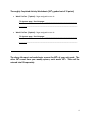
Any other specific TA requests:
____________________________________________________________
2
____________________________________________________________
____________________________________________________________
____________________________________________________________
Selected In-Class Section [6 points]: {3-5 paragraphs, ~1 page}
This week's selection is: Weekly Activity 6, In-Lab Section 3
Write a "mini-report" for this section of the lab manual. Describe what you did
succinctly, and then what you found accurately. Then explain what the result means
and how it relates to some of the concepts in the previous section. You must write using
sentences & paragraphs; bulleted lists are unacceptable.
o Procedure: Do not provide a lot of specific details, but rather you should
summarize the procedure so that a student who took the course a few years ago
would understand what you did.
o Results: Do not bother to rewrite tables of data, but rather refer to the page
number on which it is found. State any measured values, slopes of ilnes-of-bestfit, etc. Do not interpret your results, save any interpretation for the discussion.
o Discussion: Analyze and interpret the results you observed/measured in terms of
some of the concepts and equations of this unit. It is all right to sound repetitive
with other parts of the report.
Open-Ended / Creative Design [6 points] – {3-5 paragraph, ~1 page} Choose one of the
open-ended experiments from the two weekly activities to write about. Describe your
experimental goal and the question you were trying to answer. Explain the ideas you
came up with and what you tried. If your attempts were successful, explain your results.
If your attempts resulted in failure, explain what went wrong and what you would do
differently in the future. You must write using sentences & paragraphs; bulleted lists are
unacceptable.
Graphs [4 points] - {attach to typed report} Graphs must be neatly hand-drawn during
lab and placed directly after your typed discussion (before your quizzes and selected
worksheets). Your graphs must fill the entire page (requires planning ahead) and must
include: a descriptive title, labeled axes, numeric tic marks on the axes, unit labels on the
axes, and if the graph is linear, the line of best fit written directly onto the graph.
3
Thoroughly Completed Activity Worksheets [30%, graded out of 15 points]
Week 5 In-Class [7 points]: Pages assigned to turn in:
_TA signature page, Post-lab pages, ____________________________________
___________________________________________________________________
Week 6 In-Class [8 points]: Pages assigned to turn in:
_TA signature page, Post-lab pages, ____________________________________
___________________________________________________________________
The above lab report and worksheets account for 80% of your unit grade. The
other 20% comes from your weekly quizzes, each worth 10%. These will be
entered into D2L separately.
4
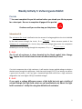
Weekly Activity 5: Vulture Iguana Rabbit
Pre-Lab
!
You must complete this pre-lab section before you attend your lab to prepare
for a short quiz. Be sure to complete all pages of the pre-lab.
Continue until you see the stop pre-lab picture:
Subsection 0-A
The resistance of a circuit is defined to be the amount of voltage applied to the circuit divided
V
by the total current through the circuit, Rtotal total applied . When someone speaks of the
Itotal
resistance of a component of a circuit, they mean the voltage drop across the component
V
divided by the current flowing through the component, Rcomponent drop across component.
Ithrough component
¿
0-A-1
The SI unit of resistance is ohms denoted by the Greek capital letter Omega
[Express the SI unit of ohms in terms of other electricity SI units.
If a circuit component has a high resistance, it will require a larger applied voltage to obtain a
desired current trough the component. Note that even though a 12 [V] car battery can deliver
a great deal of power, it will not light a household light bulb which has a high resistance
designed for the much higher 120 [V] household voltages.
¿
0-A-2
If you apply a voltage difference across a light bulb but only get a trickle of
current through the light bulb, what can you qualitatively say about the light
bulb’s resistance? Justify this using the definition of resistance.
5
Imagine you are in the desert and there is a vulture flying in the sky and a rabbit and an iguana
walking on the ground. The rabbit sees the vulture flying over the iguana! This is a pneumonic
V
Vulture
device to remember the definition of resistance: R
.
Rabbit sees
I
Iguana
¿
0-A-3
What would the iguana see? What would the vulture see? Write two new
equations relating V, I and R based upon this pneumonic device. This is merely
a way to avoid silly errors when trying to rearrange the equation R
V
.
I
V
should be the same for different
I
voltages. Therefore, a particular component may have different resistances for different
applied voltages. For example, a diode will have a very large resistance until the applied
voltage potential difference reaches a certain value and then drop to nearly zero for larger
voltages. Components that have a resistance that depends on the voltage applied are called
non-ohmic. For introductory students, we usually work with ohmic devices in most (but not all)
V
of the labs. For an ohmic resistor, the equation Rconstant
implies the resistance is the same
I
value no matter what voltage is applied, and the current changes with voltage to keep the ratio
V
constant.
I
There is no reason to suspect a priori that the ratio of
It should be noted that resistance of a material often depends on its temperature. Since a light
bulb gets hotter as more voltage is applied across it (and so more current flows through it, and
it consumes more power, P I V ), the light bulbs resistance grows with its brightness. So a
light bulb definitely is non-ohmic.
¿
0-A-4
If a 1.5 [volt] battery is discharged through a 2.5 [ resistor, what is the current
through the resistor?
6
Real batteries have internal resistances that affect their performance by decreasing their
effective voltage. For example, if you take a 1.5 V battery and attach a 0.000001 ohm resistor
(like a wire), you will NOT obtain a 1,500,000 amp current! As the battery tries to supply a large
current, it will heat up and its internal resistance will grow thereby lowering the voltage
supplied to the resistor until only a small voltage is actually applied to the resistor.
¿
0-A-5
If your 12 [volt] car battery dies unexpectedly, why can't you substitute your car
battery with eight 1.5 [V] batteries (8 x 1.5 [V] = 12 [V] in series) to get home?
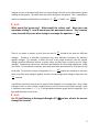
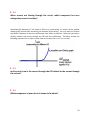
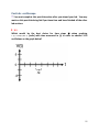
Answer the questions about each of the following graphs.
¿
0-A-6
Does the below graph describe an ohmic resistor? What does the slope of this
graph represent?
¿
0-A-7
Does this graph describe an ohmic resistor?
7
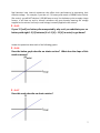
¿
0-A-8
Does this graph describe an ohmic resistor?
¿
0-A-9
Does this graph describe an ohmic resistor?
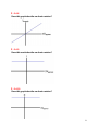
¿
0-A-10
Does this graph describe an ohmic resistor?
8
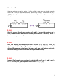
Subsection 0-B
When two resistors are put into series, it is often useful to treat them as a single composite
resistor and to find the equivalent resistance of this single resistor. The formula for this is
Requivalent R1 R2 . You will learn to derive this by answering the following questions using the
below picture.
¿
0-B-1
Label the current through each resistor as I1 and I2. Because the resistors are in
series, how are these two currents related (think marbles in a hose)? What is
the reason for your answer?
¿
0-B-2
Label the voltage difference across each resistor as V1 and V2. Write an
equation relating V to V1 and V2. Here you must use the idea that the sum of all
voltage differences in a circuit must be zero or else one could extract an infinite
amount of energy from the electrons whirling around the loop.
¿
0-B-3
Now use Ohm’s law in your previous to substitute R1 and I1 for V1, and R2 and I2
for V2. (At this point, your equation should read V I1R1 I2R2.)
9
¿
0-B-4
Now use your answer from 0-B-1 by substituting I for I 1 and I 2 since I 1 I 2 (there
is no reason to differentiate between the current in the two resistors so just
write I). Distribute the I from the addition on the right hand side of the
equation to get V IR1 R2 . Explain why this tells you that two resistors in
series have an equivalent resistance of R1 R2 .
¿
0-B-5
If V 3 [V] , R1 4 [] , and R2 6 [] , find the current through the resistors.
¿
0-B-6
If V 3 [V] , R1 4 [] , and R2 6 [] , find the current through the battery
(remember, charge can never pile up anywhere in a circuit).
10
Subsection 0-C
Now examine two resistors in parallel. We would like to be able to treat them as a single
equivalent resistor to make examining the total behavior of the circuit easier. The derivation is
given below without explanations.
¿
0-C-1
You will need to provide the derivation with explanations for each step in your
lab report so work through it now to make sure you understand. Write an
explanation down for every step. (Explain using either physics concepts or
mathematical operations.)
Itotal I1 I2
V V
1 2
R1 R2
V V
R1 R2
1
1
V
R1 R2
Therefore,
Rparallel
1
1
1 .
R1 R2
11
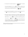
Subsection 0-D
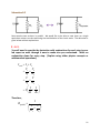
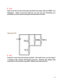
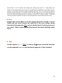
Solving compound circuits is a very important skill. Here is an example where you must solve
for the total current (which is the current through the battery IBattery), the total resistance Rtotal
as well as the voltages across and currents through each of the components:
The strategy is to pretend that the two series resistors are equivalent to a single resistor:
First collapse the two series components: RA R1 R2 5 [] . Since this is actually
the total resistance of the circuit (assuming an ideal battery which has zero internal
V Battery
2 [A] .
resistance), you may use Ohm’s law to find the total current: I Battery
RA
Since charge cannot pile up anywhere in a circuit, this is also the same current as in R1
and R2: I 1 I 2 2 [A] .
You can now find the voltage across R1: V1 R1 I 1 2 [V] and R2: V2 R2 I 2 8 [V] .
Due to the conservation of energy, you expect the voltages across the components to
add to the total supplied by the battery and indeed 2+8=10.
12
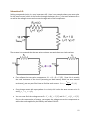
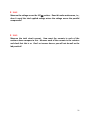
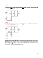
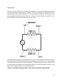
As more components are added to the circuit, the problem solving becomes more complex.
Here you must solve for the total current IBattery, the total resistance Rtotal as well as the voltages
across and currents through each of the components:
First find the total equivalent resistance. This must be done in steps:
13
First collapse the first two parallel components: R A
1
1
1
R1 R 2
2
[] . Then collapse
3
14
[] . Since this is actually the total
3
resistance of the circuit (assuming an ideal battery which has zero internal resistance),
V Battery 27
you may use Ohm’s law to find the total current: I Battery
[A] .
RB
14
the two series components: R B R3 R A
Since charge cannot pile up anywhere in a circuit, this is also the same current as in R3:
54
27
I3
[A] . You can now find the voltage across R3: V3 R3 I 3
[V] .
14
7
Now note that R1 and R2 are in parallel so that V1=V2 (remember conservation of energy
in circuit loops). Subtract V3 from the total voltage to find the voltage across these
54 9
=
[V] . Now you can easily find the current in
parallel resistors: V1 V2 9
7 7
V
V
9
9
[A] . Check your parallel currents
each component: I 1 1 [A] and I 2 2
R1 7
R2 14
9 9 27
[A] , which is the total current
as they must add up to the total I 1 I 2
7 14 14
coming into the parallel components. Also note that since R2 has twice the resistance of
R1, only half as much current flows through that resistor.
The logic is beautiful, but it takes a good amount of practice to learn how to "work inward then
back outward" on these kinds of problems.
14
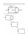
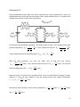
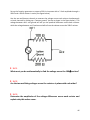
¿
0-D-1
The following compound circuit shows a 10 [V] battery discharging through two
parallel 2 [ohm] resistors and two 8 [ohm] resistors in parallel. The two parallel
pairs of resistors are themselves in series. You need to find all the unknown
component voltages and currents as well as the total circuit resistance and
current. You may assume the battery is ideal (has no internal resistance). The
answers are given so that you can check your work. Hint: treat each parallel set
of resistors as a single equivalent resistor.
15
(This page intentionally left blank.)
16
In-Lab Section 1: experimentally determining resistance
¿
1-1
Make a sketch of the small board of resistors provided to you and use your
DMM to measure the resistance of each with as much accuracy as possible.
Label the values on your sketch. (There is never any reason to trust the values
written on the resistors or the color codes!)
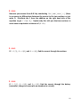
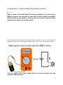
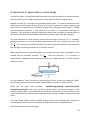
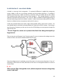
The picture below is provided to remind you that to measure current, you must divert the
charges flowing in the circuit through the DMM so that it may "count" them as pass through.
!
Do not apply such a large voltage that the resistor becomes very hot,
dangerous and non-ohmic.
17
¿
1-2
Experimentally verify that the “1,000” [ resistor on your resistor board is
ohmic at room temperature. Do this by gathering (voltage, current) data and
making the appropriate graph. Your graph of your data should quite nicely
show the linear behavior of your ohmic resistor. The correct choice of (V vs. I)
or (I vs. V) should give your resistance as the slope and thereby check its
experimentally measured resistance (see how close you got with your DMM,
redo if bad).
(write data here and plot graph on separate graph paper)
¿
1-3
Experimentally verify that the 100 [ resistor and the 200 [ resistor in series
produce an equivalent resistance of 300 [ by taking (voltage, current) data
and making the appropriate graph. Your voltage data should be gathered from
across both resistors simultaneously since you want to treat them as a single
resistor and find their equivalent resistance. Remember that the current is the
same through both resistors.
!
Do not apply such a large voltage that the resistor becomes very hot,
dangerous and non-ohmic.
(write data here and plot graph on separate graph paper)
18
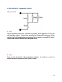
In-Lab Section 2: compound circuits
Subsection 2-A
¿
2-A-1
The circuit shown above has 3 resistors in parallel, which together are in series
with another resistor. Extend your equation for the parallel resistance of two
resistors to find the equivalent resistance of three resistors in parallel (SI units).
Also provide a small sketch of the simplified circuit.
¿
2-A-2
Now use the formula for the equivalent resistance of resistors in series to
predict the total resistance of this circuit (SI units).
19
¿
2-A-3
Now set up the circuit and test your prediction by simply using the DMM as an
Ohmmeter. Redo 2-1 and 2-2 until you are sure you are calculating your
prediction correctly and/or making the measurement correctly.
Subsection 2-B
¿
2-B-1
Power the circuit from the previous problem. Be careful not to use too large of
a voltage or the resistors will become very hot. Measure the voltage drop
across each of the resistors in parallel. What do you find and why?
20
¿
2-B-2
Measure the voltage across the 10 [ resistor. Does this value make sense, i.e.,
does it equal the total applied voltage minus the voltage across the parallel
components?
¿
2-B-3
Measure the total circuit current. How must the currents in each of the
resistors above compare to this. Measure each of the currents in the resistors
and check that this is so. Don’t cut corners here or you will not do well on the
lab practical!
21
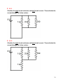
Subsection 2-C
Solving compound circuits made from ohmic components is a very important skill. Here is an
example where you must solve for total current (IBattery) total resistance (Requivalent) as well as the
voltages and currents in each of the components:
First find the total equivalent resistance. This must be done in steps. First collapse the first two
1
2
1
6
parallel components: R12
. Then collapse this with R3: R123
.
1
1
1
1
3
11
R1 R2
R12 R3
50
Finally collapse these with the remaining R4: Reffective R4 R123 .
11
With the total resistance, you may use Ohm’s law to find the total current:
VBattery 99
99
IBattery
Amps. This is also the same current as in R4: I4 Amps. You can now
50
Reffective 50
198
Volts .
find the voltage across R4: V4 R4 I4
25
Now note that R1, R2 and R3 are in parallel so that V1=V2=V3 (conservation of energy in loops).
Subtract V4 from the total voltage to find the voltage across each parallel component:
198 27
V1 V2 V3 9
=
Volts .
25 25
Now you can easily find the current in each component: I1
and I3
V3 27
Amps.
R3 75
V1 27
V
27
Amps, I2 2 Amps,
R1 25
R2 50
22
¿
2-C-1
Calculate the total circuit resistance and total circuit current. Then calculate the
current through the 3 ohm resistor.
¿
2-C-2
Calculate the total circuit resistance and total circuit current. Then calculate the
current through the 3 ohm resistor.
23
¿
2-C-3
Calculate the total circuit resistance and total circuit current. Then calculate the
current through the 3 ohm resistor.
¿
2-C-4
Calculate the total circuit resistance and total circuit current. Then calculate the
current through the 3 ohm resistor.
¿
2-C-5
Would you have predicted that the total current for the third circuit would be so
different from the total current in the fourth circuit? Explain why the addition
of the single 1 [ resistor in the fourth circuit increases the total current by
almost 300%. Your answer and explanation:
24
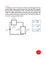
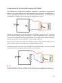
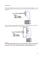
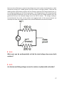
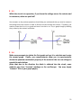
In-Lab Section 3: the internal resistance of a DMM
Your DMM has a very large internal resistance. Sometimes it is important to know this value
because if you try to measure circuits with comparably large resistances, the DMM begins to
carry an appreciable part of the circuit current throwing off measurements. For example, in the
following picture a DMM is used to measure the voltage across a resistor.
Consider what happens if the internal resistance of the DMM is near to that of R1. It behaves
like any resistor by letting current flow through it. Since the resistance of R1 is so large, more
current than is supposed to flows through the DMM. Since DMM actually measures voltage by
determining the current flowing through it, a false reading is obtained.
We can find the internal resistance of the DMM by deriving a useful formula relating RDMM to
other variables, and then measuring the other variables experimentally.
Theoretically examine the circuit with R1 placed in series with the DMM. (You won’t be asked
to set up the circuit and make measurements until a later problem.)
¿
3-1
Predict the total resistance of this circuit from the two component resistances.
25
¿
3-2
Calculate the total current I in the circuit in terms of V, R1 and RDMM.
¿
3-3
Since the total current is also the current through RDMM, you may also calculate I
in terms of RDMM and VDMM.
¿
3-4
Equate I in your previous two answers in order to find an equation relating V,
R1, RDMM, and VDMM.
¿
3-5
Rearrange your previous answer in order to obtain: RDMM
VDMM
R1 .
V - VDMM
¿
3-6
With the aid of your derived formula (given in 3-5), use your DMM and the 1
M resistor to find the internal resistance of your DMM.
26
In-Lab Section 4: authentic assessment
Set up a working circuit that simultaneously uses three resistors not all in series and measure
the current through each resistor separately using an ammeter. Be sure not to apply too large
of a voltage. Sketch your circuit and label the resistances and measured currents of each
resistor.
¿ 4-1
Show a student in a different group that you can successfully measure the
current through a resistor using an ammeter. Once you are successful, have
them sign below. Note: if someone is stuck, please give them advice!
"Yes, I have seen this successfully use make an ammeter measurement. They
have not forgotten the major difference between measuring voltage and
measuring current with a DMM!"
Student Signature:___________________________________________________
27
In-Lab Section 5: open-ended / creative design
At each lab station is a long board with Nichrome wire (nickel-chromium) of various thickness.
Nichrome wire has a very high resistance and is often used in simple heating elements.
Imagine you work for a company that produces resistive wire. You need to determine some
basic technical specifications for the resistive wire for use in your sales catalog. Reporting the
total resistance is useless since this depends on how thick and long a particular wire is. Instead
you should report resistivity with units of m, which is a microscopic description of
resistance. This will allow an engineer designing a coffee maker the ability to calculate the size
and shape of the Nichrome heating element that they need to order from your company.
The total resistance of a wire increases linearly with the length of the wire, R L . However,
the total resistance of a wire is inversely proportional to the cross sectional area of a wire,
1
R . This is because increasing the thickness of the wire gives the electrons more surface to
A
flow through so that they encounter less “electrical friction”.
When someone knows the proportionalities of a variable, they can write an equation for that
L
variable with an unknown constant: R . Here the resistivity is a constant of
A
proportionality relating the total resistance of a wire to its length and area. Find the resistivity
of Nichrome wire.
You are allowed to "cheat" by talking to other groups for ideas, but are not allowed to "cheat"
by just stating an answer you may already know, looking it up online or asking your TA.
Below you are given three prompts:
hypothesizing/planning, observations/data,
calculations/conclusion. Your job is to figure out the answer using these prompts as your
problem-solving model. In the event that you should run out of time, you may not discover the
correct answer, but you should make an attempt at each prompt. Grades are based on honest
effort.
Your open-ended solution should probably include some of the following items: sketches of
circuit diagrams, tables of data, calculations, recorded observations, random ideas, etc.
Write at the prompts on the next page.
28
¿
5-1
hypothesizing/planning:
¿
5-2
observations/data:
¿
5-3
calculations/conclusion
I, the physics 241 laboratory TA, have examined this student's Weekly Activity pages and found
them to be thoroughly completed.
!
TA signature: _______________________________________________________________
29
Post-Lab: vulture iguana rabbit
!
You must complete this post-lab section after you attend your lab. You may
work on this post-lab during lab if you have time and have finished all the other
lab sections.
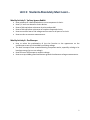
¿
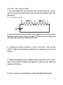
X-1 Resistors in Series
a) How does the total resistance of the circuit compare to the resistance of each
individual resistor (smaller, larger, the same)? Without equations, explain why
you expect the total resistance should be this way.
b) Compare the currents at points a, b and c in the circuit. How are they
related? Without using equations, explain why you expect the current to act
this way.
c) Compare the magnitude of the voltages between point pairs a-b, b-c, and a-c.
How are they related? Without using equations, explain why you expect the
voltage to act this way.
d) If these resistors are two light bulbs, explain which light bulb is brighter.
30
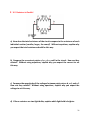
¿
X-2 Resistors in Parallel
a) How does the total resistance of the circuit compare to the resistance of each
individual resistor (smaller, larger, the same)? Without equations, explain why
you expect the total resistance should be this way.
b) Compare the currents at points a, b, c, d, e, and f in the circuit. How are they
related? Without using equations, explain why you expect the current to act
this way.
c) Compare the magnitude of the voltages between point pairs a-b, c-d, and e-f.
How are they related? Without using equations, explain why you expect the
voltage to act this way.
d) If these resistors are two light bulbs, explain which light bulb is brighter.
31
(This page intentionally left blank.)
32
Weekly Activity 6: Oscilloscope
Pre-Lab
!
You must complete this pre-lab section before you attend your lab to prepare
for a short quiz. Be sure to complete all pages of the pre-lab.
Continue until you see the stop pre-lab picture:
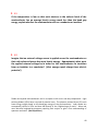
Before actually using the oscilloscope, you need to be able to understand and predict what will
appear on the oscilloscope screen. An oscilloscope is a device that measures voltage
differences over time. It can be used to study rapidly oscillating voltages. For example, the
voltage supplied by a wall outlet oscillates at the incredibly slow rate of 60 Hz. Hertz [Hz] is the
SI unit for linear frequency representing the number of oscillations per second. However, the
oscilloscope can easily measure an oscillation of 1MHz or more.
Most DMMs indicate that they can measure an oscillating voltage. However, a DMM can only
make average measurements of sinusoidal 60 Hz voltages. In other words, a DMM is only
useful for alternating current measurements (AC) on household circuits, not radios or other
electronics.
¿
0-1
What is the period T of one oscillation for a linear frequency f = 5 [MHz]
sinusoidal oscillating voltage? What is the angular frequency? Remember:
T=1/f with SI units [s] and =2f with SI units [1/s].
An oscilloscope is needed to examine voltages that change in time. Mathematically, a voltage
that oscillates sinusoidally can be written as a time-dependent function (with time measured in
seconds [s]):
V(t) 6sin(2 60 t) [volts],
where f=60 [Hz], = 2 60 [1/s], and Vamplitude=6 [volts].
¿
0-2
For the sinusoidal voltage V (t ) 8.21sin(255 t ) [volts], find f, , T, and Vamplitude (all
in SI units).
33
The simplest way to use an oscilloscope is measuring a constant voltage which even a DMM can
do.
¿
0-3
Imagine you have a 1.5 [V] battery and you measure the voltage every second
for 5 [s]. Make a data table to describe this (t vs. V). Then use the data table to
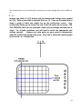
make a graph of what you would see on the oscilloscope screen. Your
oscilloscope allows you to control the size of the tick marks on its screen. FOR
THIS PROBLEM ONLY you are provided a choice of axis settings and selection of
origin. For all other problems, you will need to select the appropriate axis
settings yourself.
Connect your data points on your graph to demonstrate
what the oscilloscope would really show. (Hint: this is about the simplest graph
in the world, i.e., a straight line.
34
¿
0-4
Now imagine you have a 6 [V] sinusoidal power supply
with a frequency of f=60 [Hz]. What is VMAX and VMIN
for this voltage? _____________ and ___________.
What is the period of one oscillation?
_________________. Mathematically, this voltage is
described as V(t) 6sin(2 60 t) where 2 60 is the
angular frequency, . Fill in the data table below by
plugging the times into the sinusoidal voltage formula
in radian mode). Then
(calculator
make a graph on the
oscilloscope. Be sure to label your axes and choose
your units per division on the time axis wisely so that
all your data fits on the screen.
35
¿
0-5
Now imagine you have two sinusoidal voltage signals. Both have a frequency of
60 [Hz], but V1 has an amplitude of 6 [V] while V2 has an amplitude of 12 [V].
Furthermore, V2 lags behind V1 out of phase by 90o. Without making a data
table, sketch what would appear on the oscilloscope. Feel free to use a
graphing calculator with the functions
V1(t) 6sin(2 60 t) and V2 (t) 12sin2 60 t .
2
Be sure to label your axes and choose appropriate time and voltage units per
division for your graph.
36
¿
0-6
Finally, imagine taking the two alternating voltage sources from the previous
problem, but now graph V1(t) on the x-axis and V2(t) on the y-axis. In
oscilloscope terminology, this is called an XY plot. Thus we are graphing V2 vs.
V1. Note: this is a voltage vs. voltage graph NOT a voltage vs. time graph. Make
a data table using some points of common time provided below and the
formulas from the previous sections. Use this table to graph V2 vs. V1. Be sure
to label your axes and choose appropriate voltage units per division for your
graph.
37
(This page intentionally left blank.)
38
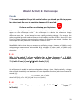
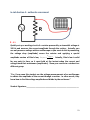
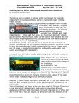
In-Lab Section 1: semiconductors and quantum mechanics
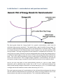
The above graph shows the 'energy bands' for a generic semiconductor, which must be
calculated using quantum mechanics. This graph shows a plot of possible 'energy states' for
electrons inside semiconducting material (such as one would find in a computer chip). Though
an in-depth discussion of this advanced topic cannot be given here, the most essential points
can be provided. The lower energy band of a semiconductor is completely full of electrons. It is
out of room so to speak. Electrons in this low energy band cannot accept extra energy unless it
is sufficiently large enough to move the electron into the next energy band called a conduction
band. Thus a very cold semiconductor cannot conduct electricity because the electrons are
stuck in the 'valence band'. But if enough voltage is applied to a semiconductor, the electrons
can be given enough energy to escape the valence band and move into the conduction band.
And so you may now guess at how semiconductors provide us a way to create 'digital'
electronics, that is, electronics that is either 'on' or 'off', '1' or '0'. With semiconductors, we
either provide enough voltage to allow them to conduct electricity ('on' or '1') or we don't apply
a voltage and the semiconductor cannot conduct electricity ('off' or '0').
The most important property of a semiconductor is the minimum distance between the valence
and the conduction band because this represents the amount of energy needed to turn on the
semiconductor and enable to conduct electricity. This is called the band gap energy.
39
¿
1-1
If the temperature is low so that each electron in the valence band of the
semiconductor has an average kinetic energy much less than the band gap
energy, explain whether the semiconductor acts as a conductor or insulator.
¿
1-2
Imagine that an external voltage source is applied across the semiconductor so
that each valence electron has more kinetic energy. Approximately what must
the applied external voltage be in order for the semiconductor to transition
from an insulator to a conductor? (Hint: energy equals charge times electric
potential.)
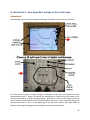
Diodes are layered semiconductors and in a simple circuit act as one-way components. Light
emitting diodes (LEDs) have a myriad of practical uses. The photons emitted by an LED each
have energy roughly equal to the band gap energy of the semiconductor. Laser diodes are
conceptually similar to LEDs and have led directly to the “digitized age of music”. More and
more electrical engineering programs requiring their majors to gain a firm understanding of
quantum mechanics. (Not a question.)
40
In-Lab Section 2: time dependent voltage on the oscilloscope
Subsection A
The following picture shows the digital oscilloscope and labels its most common features.
You now need to practice using the digital oscilloscope so that you are prepared to make
measurements with it. Keep in mind that the oscilloscope is simply a tool that allows you to
analyze the details of a rapidly changing voltage. With that in mind, you will now practice the
more common measurements that are made as well as their uses. Your TA will most likely have
demonstrated how to use it at the beginning of lab, but each student will forget different
features at the beginning stages so work together and ask lots of questions.
41
¿
2-A-1
Hook the two output leads of your function generator to the two leads of
channel 1 of your oscilloscope. Use the oscilloscope to examine the voltage vs.
time graphs of many different sine waves, square waves and saw tooth waves
created by the function generator (oscillating voltage supply). Be sure to
experiment with all sorts of frequencies, voltage amplitudes and DC offsets.
Practice making the voltage functions fit nicely on the oscilloscope screen. Take
the time to twiddle every knob and switch. Once you feel comfortable with
your understanding of each operational control of the oscilloscope and function
generator, write a short statement explaining what each control does. But don't
write a "user's manual".
42
Subsection B
Use the function generator to create a 5-volt sine wave with 1,000 Hz frequency. Use the
oscilloscope (as shown in the picture below) to set the function generator amplitude correctly
at 5.0 Volts.
Use this sinusoidal voltage to power a 1,000 resistor. Use the oscilloscope to measure the
voltage drop across the resistor (set up as shown in the picture below).
¿
2-B-1
What should the voltage drop across the resistor be according to conservation
of energy? Be sure your measurement with the oscilloscope indicates this.
43
Now switch to a 10 resistor and examine the voltage drop across it. Theoretically, this
smaller resistor should still have the same 5 Volt difference (amplitude) as the 1,000 resistor.
However, you should notice the voltage amplitude decrease. This is a result of the function
generator output changing. The smaller resistor will allow a greater current to flow through the
circuit, but the function generator has a maximum current that it is able to produce. Therefore,
once the resistance becomes too low, the function generator cannot output the full 5 volts.
¿
2-B-2
Imagine that you are about to use the function generator to power a circuit.
Explain why you should measure the amplitude of the source voltage coming
from the function generator after you have hooked up the function generator to
your circuit. (Many students get bad data because they forget about this subtle
issue.)
¿
2-B-3
Use the equation Iamplitude
Vamplitude
in with the 10 resistor to find the maximum
R
current amplitude Iamplitude,max that the function generator is able to produce.
44
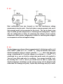
Subsection C
You may use the oscilloscope to measure the voltages of two circuit components separately
using the oscilloscopes two separate channels. The two oscilloscope channels each have a
ground (black lead), and both grounds are actually connected inside the oscilloscope so that
only one ground needs to be connected to the circuit. A common mistake is for students to try
and "sandwich" each component with both channel leads:
! WRONG!
The problem with using both channel grounds is that 1) it is not necessary since they connected
internally, and 2) if they end up being connected to different parts of the circuit, they short the
circuit out (because they are connected internally). Sometimes students use an external wire
to connect both black leads of the oscilloscope channels to remind themselves of this so they
don't end up making mistakes (on their lab practicals).
! Never use both channel grounds.
Only use one of them, either will do.
45
Set up the function generator to output a 200 Hz sine wave with a 3 Volt amplitude through a
100 and a 200 resistor in series (see figure below).
Use the two oscilloscope channels to measure the voltage across each resistor simultaneously
on both channels by setting up a “bottom ground” (set up as shown in the figure below). The
voltage between red 1 and ground will tell you the potential difference across both resistors
while the voltage between red 2 and ground will tell you the voltage across the 200 resistor.
¿
2-C-1
What must you do mathematically to find the voltage across the 100 resistor?
¿
2-C-2
Are the two oscillating voltages across the resistors in phase with each other?
¿
2-C-3
Determine the amplitudes of the voltage differences across each resistor and
explain why this makes sense.
46
Now use the oscilloscope to measure the voltage across each resistor simultaneously on both
channels by setting up a “middle ground” (set up as shown in the figure below). Note that the
middle ground measurement requires that the function generator NOT be grounded (use a 3to-2 prong plug adapter on the function generator). The voltage between red 1 and ground will
tell you the potential difference across the 100 resistor while the voltage between red 2 and
ground will tell you the inverted voltage across the 200 resistor. The voltage reading is
inverted because the order of the positive and negative leads of the second channel are
reversed; the same thing would happen with a simple DMM when you switch the leads.
¿
2-C-4
What must you do mathematically to find the total voltage drop across both
resistors?
¿
2-C-5
Are the two oscillating voltages across the resistors in phase with each other?
47
¿
2-C-6
Determine the amplitudes of the voltage differences across each resistor and
explain why this makes sense.
Using the same middle ground set up as in the last problem, measure the changing voltage
across both resistors in “X-Y” mode so that one of the resistor voltages is plotted on the x-axis
and the voltage of the other resistor is plotted on the y-axis. You should see an “ellipse edge
on” i.e. a diagonal line.
In the prelab, you found an elliptical x-y graph because the voltages being plotted were out of
phase. However, in today’s lab we don’t have any components that cause phase shifts (i.e.
capacitors or inductors). Since both voltages are oscillating in phase they will both reach zero
simultaneously. Thus they will trace a diagonal line that some experimentalists simply consider
an ellipse viewed “on-edge”.
¿
2-C-7
How does the height and width of the “ellipse” in your x-y measurement relate
to the voltage amplitudes across each resistor?
48
In-Lab Section 3: non-ohmic diodes
A diode is a one-way circuit component. If a potential difference is applied the wrong way
across a diode, it will act as an infinite resistance and not conduct electricity. If a voltage is
applied correctly across a diode and above a minimum value, the diode will act with almost
zero resistance and allow the current to flow through it. This strange behavior is entirely
quantum mechanical and non-Ohmic. This "turn on" effect is related to the band gap energy of
the semiconducting materials the diode is made of. (Note that vacuum tubes perform a similar
function to diodes and are not quantum mechanical in nature.)
Create the powered diode circuit with a light emitting diode (LED) in series with a resistor. On
many diode boards, the diode is already soldered in series with a 330 resistor. Start using a
very low source frequency so that you can see the LED blinking as current passes through the
LED half the time.
! Do not forget the resistor as it protects the diode from being destroyed by a
large current.
Then set up your oscilloscope in the “bottom ground” set up to measure the voltage across the
resistor on the y-axis and the applied voltage on the x-axis:
Since the voltage source is oscillating, some of the time it is in the correct direction to "turn on"
the diode so that current can flow, and some of the time is in the opposite direction so that no
current flows.
¿
3-1
When current flows through the circuit, which component has zero voltage drop
across it and why?
49
¿
3-2
When current not flowing through the circuit, which component has zero
voltage drop across it and why?
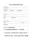
Experimentally determine if the diode is Ohmic by constructing its current versus applied
voltage graph (should look something like example figure below). You may want to increase
the source frequency so that the oscilloscope trace makes a solid line. Note that you cannot
directly measure the current through the LED with the oscilloscope. Therefore, answer the
following questions first in order to learn how to construct the ILED vs. Vapplied graph.
¿
3-3
In this circuit, how is the current through the LED related to the current through
the resistor?
¿
3-4
Which component of your circuit is known to be ohmic?
50
¿
3-5
While the circuit is in operation, if you know the voltage across the resistor and
its resistance, what can you find?
Your answers to the previous questions should help you understand that you need to measure
the voltage across the resistor in order to find the current through the resistor. Therefore, you
need to create the VR vs Vapplied graph and turn it into the ILED vs. Vapplied graph simply by dividing
the y-values by the resistors resistance:
¿
3-6
Make measurements to obtain the first graph and use it to calculate and create
the second graph. Finally, your measurements allow you to experimentally
obtain the quantum mechanical property of the material: the turn on voltage so
record this value below.
(Note that due to the direction the diode is soldered into the circuit, some
students may have 'inverted' readings on the oscilloscope. You may simply
“uninvert” this on your graph paper.)
51
(This page intentionally left blank.)
52
In-Lab Section 4: authentic assessment
¿
4-1
Quickly set up a working circuit of a resistor powered by a sinusoidal voltage at
100 Hz and measure the current amplitude through the resistor. Actually, you
can only measure voltage with an oscilloscope so you must do this by measuring
the voltage drop (amplitude) across the resistor and applying a special
amplitude version of Ohm’s law, I amplitude
Vamplitude
R
. Actually, Ohm's law is valid
for any point in time, so it must hold at the instant when the current and
voltage reach their maximums (amplitudes). Show your results to a student in a
different group:
"Yes, I have seen this student use the voltage measurements of an oscilloscope
to obtain the amplitude of the current through a resistor. In other words, they
know how to find the voltage amplitude and divide by the resistance."
Student Signature:___________________________________________________
53
In-Lab Section 5: open-ended / creative design
Prove that a light bulb is non-ohmic because of heating affects by examining the correct graph
on the oscilloscope.
You are allowed to "cheat" by talking to other groups for ideas, but are not allowed to "cheat"
by just stating an answer you may already know, looking it up online or asking your TA.
Below you are given three prompts:
hypothesizing/planning, observations/data,
calculations/conclusion. Your job is to figure out the answer using these prompts as your
problem-solving model. In the event that you should run out of time, you may not discover the
correct answer, but you should make an attempt at each prompt. Grades are based on honest
effort.
Your open-ended solution should probably include some of the following items: sketches of
circuit diagrams, tables of data, calculations, recorded observations, random ideas, etc.
¿
5-1
hypothesizing/planning:
¿
5-2
observations/data:
¿
5-3
calculations/conclusion
I, the physics 241 laboratory TA, have examined this student's Weekly Activity pages and found
them to be thoroughly completed.
!
TA signature: _______________________________________________________________
54
Post-Lab: oscilloscope
!
You must complete this post-lab section after you attend your lab. You may
work on this post-lab during lab if you have time and have finished all the other
lab sections.
¿
X-1
Which would be the best choice for time steps t when graphing
V (t ) 8 sin(5,000 t ) [volts] with time measured in [s] in order to observe 3-10
oscillations on the graph below?
55
¿
X-2
Most oscilloscopes have two channels so that two simultaneous voltage
measurements may be made. Since both share a common ground, only one of
their grounds needs to be connected to the circuit. This can be done is two
ways: a middle ground configuration or a bottom ground configuration. Explain
why one configuration is better for measuring the voltages of two separate
components, while another configuration is better for measuring the voltage of
one component and the total applied voltage.
¿
X-3
The band gap energy of pure silicon is approximately 1 eV (electron-volt) or in SI
units 1.6x10⁻¹⁹ joules (so 1 eV = 1.6x10⁻¹⁹ J). Using the formula that relates
electrical potential energy to electric potential U q V , where the band gap
energy is substituted for U and the charge of an electron, e = 1.6x10⁻¹⁹ C, is
substituted for q, you can find the voltage that would need to be applied to
"turn on" pure silicon and make it a conductor. Your answer should be 1 volt.
By checking that 1 volt is correct you should now be able to explain why
electrical engineers sometimes use the strange energy unit of [electron-volt]
rather than the SI energy unit [joule]. Explain why the energy unit [eV] is useful.
56