1
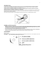
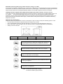
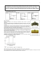
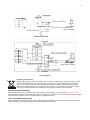
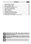
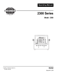
INSTRUCTIONS AND HINTS FOR THE USE, INSTALLATION AND MAINTENANCE OF GAS FUELLED BUILT-IN HOBS 220-240V~, 1-2W, 50Hz, Class I ELS-A-HG-SS90-02 1 TECHNICAL ASSISTANCE AND SPARE PARTS Before this appliance left the factory it was tested and set by specialized, expert personnel to guarantee the best functioning results. Authorised personnel must do any subsequent repairs or adjustments that may be necessary with the maximum care and attention. For this reason we always recommend contacting the nearest Assistance Centre of ours, specifying the brand, model, serial number and type of problem you are having with it. You will find the relative data printed on a label affixed under the appliance and on the label affixed on the cover. of this handbook. With this information the technical assistant can come with the right spares and guarantee a prompt job. You will find original parts and optional accessories at our Technical Assistance Centres and authorised dealers. CONTENTS 1. IMPORTANT NOTES AND PRECAUTIONS FOR USE 1 2. DESCRIPTION OF THE APPLIANCE 2 3. INSTRUCTIONS FOR THE USER: USE Presentation General Notes on safety 4 4 Gas burners 4 4. INSTRUCTIONS FOR THE USER: CLEANING AND MAINTENANCE 8 5. WHAT TO DO IF ..... 8 6. INSTRUCTIONS FOR THE INSTALLER Technical information Installation Ventilating the rooms Location and aeration Unpacking the appliance Installing and fixing the hob Gas connection Electrical connection Maintenance 8 9 9 9 9 9 10 11 12 TECHNICAL FEATURES Injecror table and heat input of the burners Electrical components 13 13 TROUBLESHOOTING 14 7. 8. 2 1. IMPORTANT NOTES AND PRECAUTIONS FOR USE You have purchased one of our products for which we thank you. We are confident that this new appliance, modern, functional and practical, made with top quality materials, will meet all your demands . This new appliance is easy to use but before installing and using it, it is important to read this handbook through carefully. It provides information for a safe installation, use and maintenance. Keep this handbook in a safe place for future reference. The manufacturer reserves the right to make all the modifications to its products that it deems necessary or useful, also in your interests, without prejudicing its essential functional and safety characteristics. The manufacturer cannot be held responsible for any inaccuracies due to printing or transcription errors that may be found in this handbook. N.B.: the pictures shown in the figures in this handbook are purely indicative.. The installation, adjustments, conversions and maintenance jobs (part “6. INSTRUCTIONS FOR THE INSTALLER”) must only be carried out by authorised personel. The installation of all-gas and combi appliances must comply with the standards in force. The appliance must only be used for what it has been made for, that is, cooking for home use. Any other use is considered improper and, as such, dangerous. The manufacturer cannot be held responsible for any harm to people or damage to things deriving from an incorrect installation or maintenance or from an erroneous use of the appliance. Once the outer wrapping and the inner wrappings of the various parts have been removed, check and make sure that the appliance is in perfect condition. If you have any doubts do not use the appliance and call in a qualified person. The packaging materials used (cardboard, bags, polystyrene foam, nails, etc.) must not be left anywhere in easy reach of children because they are a potential hazard source. To safeguard the environment all packaging materials are environment friendly and recyclable. The electrical safety of this appliance is only guaranteed if it is correctly connected to a good earth system, as prescribed by the electrical safety standards. The manufacturer declines all responsibility if these instructions are not followed. Should you have any doubts ask for an accurate control of the system by qualified personnel. Prior to connecting the appliance ensure that the rating plate data correspond to those of the gas and electricity mains (see part “7. TECHNICAL FEATURES”). To use any kind of electrical appliance there are a few basic rules that must be observed: Do not touch the appliance if your hands or feet are wet or damp. Do not use the appliance bare footed. Do not pull the lead to take the plug out of the socket. Do not leave the appliance outside under the sun, rain, etc Do not let children or anybody who is incapable to use the appliance on their own. If you are using a socket near the appliance make sure that the cables of electrical appliances you are using do not touch it and are far enough away from all hot parts of the appliance. When you have finished using the appliance check that all the controls are in the off or closed position, checking that the “0” of the knob corresponds to the “ “ symbol serigraphed on the front panel. Take the plug out of the socket before you start cleaning or servicing the appliance. In the case of a failure and/or malfunction, turn the oven off and take the plug out of the socket; do not tamper with it. All repairs or settings must be done with maximum care and attention by qualified personnel. For this reason we recommend you call the nearest Assistance Centre of ours, explaining the trouble and giving the name of the model. If an appliance is out of order or is not going to be used any more, it must be rendered useless by eliminating those parts that could be a hazard source for children when they are playing, for example: The power cable. DO NOT SPRAY AEROSOLS IN THE VICINITY OF THIS APPLIANCE WHILE IT IS IN OPERATION. DO NOT STORE OR USE FLAMMABLE LIQUIDS OR ITEMS IN THE VICINITY OF THIS APPLIANCE. NOT FOR USE IN MARINE CRAFT, CARAVANS OR MOBILE HOMES UNLESS EACH BURNER IS FITTED WITH A FLAME SAFEGUARD. WHERE THIS APPLIANCE IS INSTALLED IN MARINE CRAFT OR IN CARAVANS, IT SHALL NOT BE USED AS A SPACE HEATER 3 DO NOT MODIFY THIS APPLIANCE. This appliance is not intended for use by persons (including children) with reduced physical, sensory or mental capabilities, or lack of experience and knowledge, unless they have been given supervision or instruction concerning use of the appliance by a person responsible for their safety. Children should be supervised to ensure that they do not play with the appliance. If the supply cord is damaged, it must be replaced by the manufacturer, its service agent or similarly qualified persons in order to avoid a hazard. 2. DESCRIPTION OF THE APPLIANCE 1. 2. 3. 4. 5. 6. SABAF Semi-Rapid gas burner (SR) SABAF Rapid gas burner (R) SABAF Wok Gas Burner SABAF Auxiliary gas burner (Aux) Gas burner control knob Pan support for burners HB4801/HB4801B HB4803/HB4803B HB4802/HB4802B HB4804/HB4804B 4 HB5801/HB5801B 5 1. 2. 3. 4. 5. SABAF-AE Wok gas burner (R) SABAF-AE Rapid gas burner (R) SABAF-AE Semi-Rapid gas burner (SR) SABAF-AE Auxiliary gas burner (Aux) Gas burner control knob HB5802A/HB5802A1 HB5802D/HB5802D1 HB5801A/HB5801A1 Accessory Name User Manual Installation clip HB5801D/HB5801D1 Picture ( for reference only, physical unit maybe different) Quantity 1 Bracket Screws ST4.2x24 4 Adhesive sealing tape 1 Sealing Tape Natural gas regulator 1 Test point adapter 1 3. INSTRUCTIONS FOR THE USER: USE 6 PRESENTATION The burners are graduated in their size and rating to provide the exact heat required for every style of cooking. The burners can be equipped with safety thermocouples (Tc) for models HB4801 /HB4802 /HB4803 /HB4804 /HB5801 /HB5801A /HB5801D /HB5802A and HB5802D (see fig. 5). The burners can be equipped with safety thermocouples for models HB4801B /HB4802B /HB4803B /HB4804B /HB5801B /HB5801A1 /HB5801D1 /HB5802A1 and HB5802D1. When the flame die out because of wind, the gas will still flow from burners, it will cause burning or explosion when the flowing gas encounter naked flame; So the user cannot leave the site when the appliance is working, also pay attention to the unexpected flameout. On the top of each knob there is a printed diagram showing to which burner or heating element it refers. GENERAL NOTES ON SAFETY • • • • When the burners or plates are in use do not leave them unattended and make sure there are no small children in the vicinity. Check that pan handles are positioned correctly and always keep an eye on the pan whenever oils or fats are used as they are easily inflammable. Do not use spray cans near the appliance when it is in use. If you see any cracks on the surface of the plate, disconnect the appliance from the mains immediately. After you have used the appliance make sure that all the controls are off or closed. GAS BURNERS Manual ignition Press and turn counterclockwise the knob corresponding to the burner you wish to use, until it reaches to the “Full on” position (fig. 1) and placing a lighted match to the burner. fig.1 7 Automatic electrical ignition (only certain versions, see fig. 5, ref. AC) The command of lighting is integrated in the control knob. Press and turn counterclockwise the knob corresponding to the burner you wish to use, until it reaches to the “Full on” position (fig.1). Automatically the ignition spark shoots; keep the knob pressed until to happened lighting. Matches can be used to light the burners in a blackout. Lighting of burners equipped with safety thermocouples (only certain versions, see fig. 5, ref. TC) In the case of burners equipped with safety thermocouples you have to press and turn counterclockwise to the “Full on “ position , the knob corresponding to the burner you wish to use, and repeat the operations described previously. Once lit, keep the knob pressed for about 10 seconds to allow the safety thermocouples to warm up. If, at the end of this time, the burner fails to light, it means that the safety thermocouple is not heated to sufficiency. Repeat the operation. Optimum use of the burners To get the maximum yield with the minimum consumption of gas it is handy to keep the following points in mind: • Once the burner has been lit, adjust the flame according to your needs. • Use an appropriately sized pan and with flat bottom for each burner (see the table below and fig. 2). • When the content of the pan start to boil, turn the knob down to “Reduced rate position” (small flame). • Always put a lid on the pan. Burners Ø pans in cm Wok 22-24 Rapid 20-22 Semi-Rapid 16-18 Auxiliary 10-14 Do not place anything, eg. flame tamer, asbestos mat, between pan and pan support as serious damage to the appliance may result. Do not remove the pan support and enclose the burner with a wok stand as this will concentrate and deflect heat onto the hotplate. Do not use large pots or heavy weights which can bend the pan support or deflect flame onto the hotplate. Locate pan centrally over the burner so that it is stable and does not overhang the appliance. Use only a wok support supplied or recommended by the manufacturer of the appliance. NOTE: 1. Enclosure may be circular or square 2. These are suitable for glass panel hob 8 When a gas appliance is being used it produces heat and humidity in the room where it is installed. For this reason the room must be well ventilated, keeping the natural ventilation openings free (fig. 6) and switching on the mechanical aeration system (suction hood or electric fan, Figs. 7 and 8). If the cooker is used for a long time additional aeration may be necessary, for instance, opening a window, or a more effective aeration by increasing the power of the mechanical system if there is one. Gas connection Install in accordance with relevant gas standards and/or codes of practice applicable. Connect the elbow fitting to the appliance gas manifold connection, and check that seals between the elbow and manifold connection are in place and in good condition. For Natural gas: connect the natural gas appliance regulator (pictured opposite) with integral test point using approved gas thread tape or compound to the elbow fitting. For Universal LPG: connect the brass test point adaptor (pictured opposite) using approved gas thread tape or compound to the elbow fitting. Ensure the supply connection point, test point and natural gas regulator adjustment screw (for Natural gas installation) are accessible for testing and/or adjustment with the hotplate in the installed position. Where a flexible hose assembly is used, ensure it is approved to AS/NZS 1869, Class B. Any hose assembly used must be restrained from accidental contact with the flue outlet of an under bench oven. This hose assembly shall be suitable for connection to a fixed consumer piping outlet located as follows: Hotplates at a point 800 mm to 850 mm above the floor and in the region outside the width of the appliance to a distance of 250 mm. After connecting to gas, check for leaks using soapy solution, never a naked flame. Fit the duplicate data plate (supplied in separate bag) on a surface adjacent to the hotplate, for example, the inside of the cupboard door so it is clearly visible for any service technician. 9 4 burners 5 burners Circuit diagram Disposing of the device When disposing of the device, do not bring it to regular municipal waste containers. Instead, bring it to electrical and electronic waste recycling and reuse center. A relevant label has been put on the device, its instructions manual, or the package. The device has been manufactured of recyclable material. By bringing old device to recycling collection center, you show that you care about nature. Ask your local environmental care authority for information on location of such facilities. SETTING THE GAS PRESSURE: Fit a manometer with a 6 mm rubber hose to the test point on the regulator (for natural gas) Test point for LPG. Light Wok and Auxiliary burner on and adjust test point pressure to 1.00 kPa. Turn the two burners off and on again and recheck the pressure is same as set previously or adjust as required. TEST FOR CORRECT OPERATION: After installation and test point setting, each burner ignition and operation must be tested individually and with all burners operating. This testing must be done by the installer before leaving. 10 ADJUSTING THE BURNER MINIMUM FLAME HEIGHT: NOTE: This adjustment can only be performed by authorised service personnel. The minimum burner flame is factory adjusted for the gas type stated on the gas type label adjacent to the gas connection and should not require adjustment. Adjustment may be required if the hotplate has been converted from Natural gas to Universal LPG or vice versa. GAS CONVERSION INSTRUCTIONS: The manufacturers servicing instructions detail how authorised personnel may convert the hotplate from Natural gas to Universal LPG or from Universal LPG to Natural gas. Contact the manufacturer or agent as required. FOR SERVICE PLEASE CALL 1300 688 328 11 4. INSTRUCTIONS FOR THE USER: CLEANING AND MAINTENANCE Prior to any maintenance work or cleaning, disconnect the appliance from the electricity mains. HOB The surface of the hob, pan supports, enamelled burner caps (C) and burner heads (T) (see fig. 5) need to be cleaned after each time they are used with warm soapy water, rinsed and then dried well to keep them in good condition. Never clean when the top and components are still warm. Do not use metal or abrasive pads, abrasive powders or corrosive spray products. Never leave vinegar, coffee, milk, salty water, lemon or tomato juice for any length of time on the surfaces. WARNINGS Comply with the following instructions, before remounting the parts: Check that the heads burners and the relative burner caps, are correctly positioned in their housings (see fig. 5). Check that burner head slots have not become clogged by foreign bodies. If to happened installation or after a few times, you find a tap is difficult to open or close do not force it but call for technical assistance urgently. After use, to keep them in good condition, the plates should be treated with specific products, easily found in the shops, to keep the surfaces clean and shining. This will also prevent rust from forming. If any liquid spills over it must always be removed with a sponge. 5. WHAT TO DO IF.... Some of the problems can be caused by simple maintenance operations or something that was forgotten and can easily be resolved without having to call for technical assistance. If your appliance is not working efficiently: Make sure the gas cock is open Check the plug is in Check that the knobs are set correctly for cooking and then repeat the operations given in the handbook Check the electrical system safety switches (RCD). If there is failure in the system call an electrician Abnormal Operation Any of the following are considered to be abnormal operation and may require servicing: Yellow tipping of the hob burner flame. Sooting up of cooking utensils. Burners not igniting properly. Burners failing to remain alight. Burners extinguished by cupboard doors. Gas valves, which are difficult to turn. In case the appliance fails to operate correctly, contact the authorised service provider in your area. 6. INSTRUCTIONS FOR THE INSTALLER TECHNICAL INFORMATION The installation, the adjustments and maintenance listed in this part must only be carried out by authorised personnel. The manufacturer cannot be held responsible for any damage to persons or things deriving from an incorrect installation of the appliance. The safety and automatic adjustment devices of the appliances may, during their life, only be modified by the manufacturer or duly authorised supplier. All-gas appliances can be installed as “class 3” (fitted) in compliance with gas standards. Any side walls that overcome in height the work top, have to be to a distance of 50 least mm. The adhesive used to join the laminated plastic to the piece of furniture must be able to withstand a temperature of at least 150°C so the laminated plastic will not come unstuck. The installation of all-gas appliances must comply with the standards in force. 12 This appliance is not connected to a flue for discharge of the combustion products; therefore, it must be connected in compliance with the above mentioned installation rules. Particular attention must be paid to the instructions given below for ventilation and aeration. This hotplate must be installed in accordance with: AS 5601 - Gas Installations (for Australia) NZS 5261 – Code of Practice for the Installation of Gas Burning Appliances and Equipment (for New Zealand) Local gas fitting regulations AS/NZS 3000 – Electrical Installations (Wiring Rules) Building codes INSTALLATION This appliance shall be installed only by authorised persons and in accordance with the manufacturer's installation instructions, local gas fitting regulations, municipal building codes, electrical wiring regulations, local water supply regulations, AS 5601 - Gas Installations and any other statutory regulations. VENTILATING THE ROOMS The room where the appliance is installed must be permanently ventilated so as to guarantee correct functioning. The quantity of air needed is that required for a regular combustion of the gas and for the ventilation of the room and whose volume must be no less than 20 m 3. The natural flow of air must be direct through permanent openings in the walls (that go through to the outside) of the room to be ventilated with a minimum cross section of 100 cm2 (see fig. 6). These openings must be positioned so they cannot be obstructed. Indirect ventilation is also allowed by taking air from rooms adjacent to the one to be ventilated, strictly complying with the prescriptions of the standards in force. LOCATION AND AERATION Gas ovens must always discharge the products of combustion through extractors connected to flues or directly to the outside (see fig. 7). If it is impossible to use an extractor, a fan installed on the window or on a wall facing the outside is allowed and should be switched on each time the appliance is used (see fig. 8), provided the rules and regulations in force relating to ventilation. 2 (*) Air inlet - minimum section 100 cm UNPACKING THE APPLIANCE Once the outer wrapping and the inner wrappings of the various parts have been removed, check and make sure that the appliance is in perfect condition. If you have any doubts do not use the appliance and call your nearest Assistance Centre. Some parts are mounted on the appliance and protected by a plastic film. This protective film must be removed before ever the appliance is used. We recommend slitting the plastic film along the edges with a sharp knife or pin. The packaging materials used (cardboard, bags, polystyrene foam, nails …) should not be left anywhere within easy reach of children as they are a potential hazard source. INSTALLING AND FIXING THE HOB The measurements of the cavity made in the top of the modular cabinet and into which the hob will be recessed are indicated in fig. 9. Cupboards or hoods have to maintain a least distance of 600mm/750 mm from the top. 13 HB4801/HB4802/HB4803/HB4804/HB5801/HB4801B/HB4802B/HB4803B/HB4804B/HB5801B HB5801A/HB5802A/HB5801D/HB5802D/HB5801A1/HB5802A1/HB5801D1/HB5802D1 Any adjoining wall surface situated within 200mm from the edge of any hob burner must be a suitable noncombustible material for a height of 150mm for the entire length of the hob. Any combustible construction above the hotplate must be at least 600mm above the top of the pan supports no construction shall be within 450mm above the top of the pan supports. IMPORTANT!! Under the hob it is necessary to always apply a panel of separation in wood, positioned to a least distance of 70 mm by the bottom of the same, which has to easily be removable to allow possible operations of maintenance (see fig. 10). The hob has a special seal which prevents liquid from infiltrating into the cabinet. Strictly comply with the following instructions in order to correctly apply this seal: - Detach the seals from their backing, checking that the transparent protection still adheres to the seal itself. - Overturn the hob and correctly position seal (E) (fig. 11) under the edge of the hob itself, so that the outer part of the seal itself perfectly matches the outer perimetral edge of the hob. The ends of the strips must fit together without overlapping. - Evenly and securely fix the seal to the hob, pressing it in place with the fingers. - Remove the strip of protective paper from the seal. Insert the hooks into their relative housings (K) on the hob and set this into the hole in the cabinet. Lock it in place with the relative fixing screws (V) (see fig. 12). 14 GAS CONNECTION Prior to connecting the appliance check that the data on the rating plate affixed to the bottom of the appliance, correspond to those of the gas mains. A duplicate Data Label is supplied to adhere in an accessible area next to the appliance. This appliance is suitable for Natural Gas and Universal LPG; ensure that the available gas supply matches the Data Label. Once installed, check there are no leaks using a soapy solution (never a flame). The appliance’s gas inlet fitting is a ½” male threaded cylindrical gas type in accordance with the UNI-ISO 228-1 standards.ISO 7 The gas connection is situated at the rear of the appliance, 105mm from the right side and 45mm from the rear of the hotplate. There are two ways to carry out the connection to the main gas line: A. The hotplate can be connected with rigid pipe as specified in AS5601 . B. The hotplate can be connected with a Flexible Hose, which complies with AS/NZS 1869 (AGA Approved), 10mm ID, class B or D, no more than 1.2m long and in accordance with AS5601. Ensure that the Hose does not contact the hot surfaces of the hotplate, oven, dishwasher or other appliance that may be installed underneath or next to the hotplate. WARNING: Ensure that the hose assembly is restrained from accidental contact with the flue or flue outlet of an under bench oven. The hose should not be subjected to abrasion, kinking or permanent deformation and should be able to be inspected along its entire length. Unions compatible with the hose fittings must be used and connections tested for gas leaks. The supply connection point shall be accessible with the appliance installed. CAUTION !! Carry out the connection avoiding all kinds of stress to the appliance. ELECTRICAL CONNECTION The electrical connection must be carried out in accordance with the current standards and laws in force. Prior to connecting check that: the system and electrical sockets amperage is adequate for the appliance’s maximum power (see data label affixed on the bottom of the appliance). the socket or system has an effective earth connection in accordance with current standards and with the law. All responsibility is disclaimed if this is not complied with. When connecting to the mains with a socket: • Fit to the power cable (C)(if without – fig. 13) a standardized plug, suitable for the load which is indicated on the data label. Connect the wires making sure they correspond as shown below, and remember that the earth wire must be longer than the phase wires (fig. 14): letter L (phase) = brown wire letter N (neutral) = blue wire symbol (earth) = green/yellow wire. The power cable must be laid so that no parts of it ever reach an over temperature of 75 K. 15 For connecting do not use reductions, adapters or shunts as they could cause false contacts resulting in hazardous overheating. The appliance must be positioned so the plug is accessible. When connecting directly to the mains: - Install a multipolar switch that can withstand the appliance load, with a minimum opening between the contacts of 3 mm. - Remember that the earth wire must not be cut out by the switch. - As an alternative, the electrical connection can also be protected with a high sensitivity RCD. Before Leaving Check all connections for gas leaks with soap and water. DO NOT use a naked flame for detecting leaks. Ignite all burners both individually and concurrently to ensure correct operation of gas valves, burners and ignition. Turn gas taps to low flame position and observe stability of the flame for each burner individually and concurrently. When satisfied with the hotplate, please instruct the user on the correct method of operation. In case the appliance fails to operate correctly after all checks have been carried out, refer to the authorised service provider in your area. MAINTENANCE Maintenance Schedule No regular maintenance is required for the hotplate except cleaning. However, it is recommended the hotplate be checked and serviced by an authorised service person every 2 years. Prior to any maintenance work or before changing parts, disconnect the appliance from the gas and electricity power sources. REPLACING COMPONENTS To access the terminal board and the power cable, it is necessary to remove the hob from the cabinet by unscrewing the relative fixing screws (V) (see fig. 12). If the power cable needs changing, call an authorised Assistance Centre as it is necessary the use of special utensils. The technician will have to connect a cable with a suitable cross section (see the table on page 13) keeping the earth wire longer than the phase wires. In addition, follow the instructions giving in the “ELECTRICAL CONNECTION” paragraph. To replace other gas and electrical components, that are lodged inside the hob, it is enough to remove the work top unscrewing the fixing screws of the burners Replace the seal each time you change a tap in order to guarantee a perfect tightness between body and rail. 16 7. TECHNICAL FEATURES INJECTOR TABLE AND HEAT INPUT OF THE BURNERS (for the disposition of the hob burners, see on page 2) HB4801/HB4802/HB4803/HB4804/HB5801/HB4801B/HB4802B/HB4803B/HB4804B/HB5801B BURNERS TEST POINT PRESSURE N° DENOMINATION 1 SABAF Rapid 2 SABAF SemiRapid 3 SABAF Auxiliary 4 SABAF Wok kpa Universal LPG Natural Universal LPG Natural Universal LPG Natural Universal LPG Natural 2.75 1.00 2.75 1.00 2.75 1.00 2.75 1.00 DIAM. INJECTOR mm 0.90 1.6 0.72 1.21 0.52 0.91 0.95 1.70 HEAT INPUT With Tc MJ/h Max 9.5 10.8 6.3 6.3 3.2 3.6 10.3 11.3 HEAT INPUT Without Tc MJ/h Max 9.5 11.0 6.3 6.5 3.2 3.8 10.5 12.3 HB5801A/HB5802A/HB5801D/HB5802D/HB5801A1/HB5802A1/HB5801D1/HB5802D1 BURNERS TEST POINT PRESSURE N° DENOMINATION 1 SABAF-AE Rapid 2 SABAF-AE Semi-Rapid 3 SABAF-AE Auxiliary 4 SABAF-AE Wok 2.75 1.00 kpa Universal LPG Natural 2.75 1.00 2.75 1.00 2.75 1.00 Universal LPG Natural Universal LPG Natural Universal LPG Natural DIAM. INJECTOR mm 0.81 1.45 HEAT INPUT With Tc MJ/h Max 8.0 9.0 HEAT INPUT Without Tc MJ/h Max 8.0 9.7 6.3 6.3 3.2 3.6 10.3 11.3 6.3 6.5 3.2 3.8 10.5 12.3 0.72 1.21 0.52 0.91 0.95 1.70 ELECTRICAL COMPONENTS Description supply cable Diameter in mm Nominal data 2 H05RR-F 3X0.75mm Or H05VV-F 3X0.75mm2 17 8. TROUBLESHOOTING Servicing of the hotplates must only be done by an authorised service representative (see back of this booklet) and the hotplate must not be modified. Power must be disconnected before any servicing or maintenance is conducted. Abnormal conditions include: Excessively yellow or sooting flame type. Flame lifting off the burner ports. Flame lighting back into the burner (normally associated with a popping sound). Objectionable odour of the flames combustion products. Should a faulty condition develop in the hotplate that is not described above, refer to the following table first for possible causes and remedies prior to contacting an authorised service representative. Servicing beyond the remedies listed shall only be undertaken by an authorised service representative. FAULT POSSIBLE CAUSE No spark when gas control knob depressed. Burner not lighting when spark ignition working. Burner goes out when control knob released. Uneven flame pattern or slight flame lifting. At minimum flame setting the flame is too high. Small flame setting. on High Flame too high on High setting. Loose sparker cable. Burner not aligned properly. REMEDY Check plugged in and switched on. Check mains circuit breaker. Call authorised representative. Remove and re-fit burner. Gas supply off. Check gas supply valve on. Burner not aligned properly. Remove and re-fit burner. Burner ports blocked. Remove, clean and replace burner. Flame safeguard not activated. Re-light, allow more safeguard to activate. Flame safeguard faulty connection or broken. Call authorised representative. Burner ports blocked. Remove, clean and replace burner. Turndown control setting incorrect. Call authorised representative. Regulator faulty. Gas supply pressure low. Incorrect injector fitted. Call authorised representative. Call authorised representative. Call authorised representative. Blocked injector or gas supply tube. Call authorised representative. Incorrect utensil size. Refer to operating instructions utensil choice. Regulator faulty. Incorrect injector fitted. Call authorised representative. Call authorised representative. Incorrect utensil size. Refer to operating instructions utensil choice. No power. time for flame 18