1
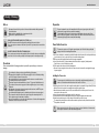
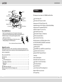
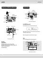
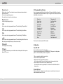
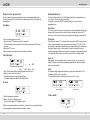
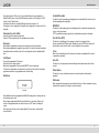
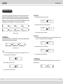
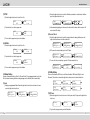
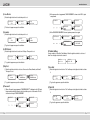
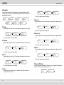
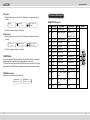
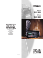
USER MANUAL
VHF Transceiver
TM-8102 / TM-8104
UHF Transceiver
TM-8402 / TM-8404
11535 W. 83rd Terrace, Lenexa, KS 66214
Phone: 913-859-9515
Toll-Free: 800-456-2071 (US Only)
Fax: 913-859-9550
Email: [email protected]
Website: www.tecnetusa.com
11535 W. 83rd Terrace, Lenexa, KS 66214
Printed in Korea
www.tecnetusa.com
Table of Contents
1. Safety / Warnings
2
2. Features
5
3. Appearance of TM-8000 Series Mobile Radio
6
7
4. Controls & Keys
5. Menu Description
14
6. Terminal Description
24
7. Specifications
26
8. Warranty Statement
28
1
www.tecnetusa.com
1. Safety / Warnings
Notices
Preparation
Government law restricts the operation of unlicensed radio transmitters within government
controlled territories.
Illegal operation is punishable by fine or imprisonment or both.
Refer service to qualified technicians only.
EXPLOSIVE ATMOSPHERES (GASES, DUST, FUMES, etc.)
Shut OFF the transceiver while refueling or while parked in gasoline service stations.
Do not carry spare fuel containers in the trunk of your vehicle if your transceiver is mounted in the
trunk area
INJURY FROM RADIO FREQUENCY TRANSMISSIONS
Do not operate your transceiver when somebody is either touching the antenna or standing within
two to three feet of it to avoid the possibility of radio frequency burns or related physical injury.
Precautions
Please read carefully the following precautions to prevent fire, personal injury, or transceiver
damage:
Do not attempt to configure your transceiver while driving, it is dangerous.
This transceiver is designed for a 13.8V DC power supply. Don’t use a 24V battery including
over DC 16V supply to power on the transceiver.
Do not put the transceiver in excessively dusty, humid or wet areas, nor unstable surfaces.
Do not modify the transceiver for any reason.
Please keep it away from interferential devices (such as TV, generator, Medical devices etc.)
Do not expose the transceiver to long periods of direct sunlight nor place it close to heating
appliances.
If an abnormal odor or smoke is detected coming from the transceiver, turn OFF the power
immediately. Contact an Authorized Dealer.
Do not transmit with high output power for extended periods; the transceiver may overheat.
Do not operate the transceiver when vehicle engine is stopped for extended periods. The
vehicle engine may not be started due to low battery.
Do not use incompatible accessories from other manufactures. It could result in damage and or
malfunction to the accessory and or to the radio.
Electronic equipment in your vehicle may malfunction if they are not properly protected from the
radio frequency energy which is present while transmitting.
Typical examples include electronic fuel injection, anti-skid braking, and cruise control. If your
vehicle contains such equipment, consult the dealer for the make of vehicle and enlist his/her aid
in determining if they will perform normally while transmitting
Power Cable Connection
The transceiver operates on 12V negative ground systems only! Check the battery polarity and
voltage of vehicle before installing the transceiver.
1. Check for an existing hole, conveniently located in the firewall, where the power cable can be passed through.
If no hole exists, use a circle cutter to drill a hole, then install a rubber grommet
2. Run the power cable though the firewall and into the engine compartment.
3. Connect the red lead to the (+) battery terminal and the black lead to the negative (-) battery terminal.
Place the fuse as close to the battery as possible.
4. Coil the surplus cable and secure it with a retaining band.
Be sure to leave enough slack in the cables so the transceiver can be removed for servicing while keeping
the power applied.
Installing the Transceiver
For passenger safety, install the transceiver securely using the supplied mounting bracket and
screw set so the transceiver will not break loose in the event of a collision.
1. Mark the position of the hole in the dash, using the mounting bracket as a template. Using a 4.2mm (5/32 inch)
drill bit, drill the holes, then attach the mounting bracket using the supplied screws.
Mount the transceiver within easy reach of the user and where there is sufficient space at the rear of the
transceiver for cable connections.
2. Connect the antenna and the supplied power cable to the transceiver.
3. Slide the transceiver into the mounting bracket and secure it using the supplied hex-headed screws.
4. Mount the microphone hanger in a location where it will be within easy reach of the user.
The microphone and microphone cable should be mounted in a place where they will not interfere with the
safe operation of the vehicle.
When replacing the fuse in the DC power cable, be sure to replace it with a fuse of the same value.
Never replace a fuse with one that is rated with a higher value.
2
3
www.tecnetusa.com
Spring Washer
2. Features
Flat Washer
5x16mm
Self-tapping Screw
Microphone
M4 x 6mm
Hex-headed Screw
The followings are the main features of the TM-8000 Series Mobile Radio:
Mounting Bracket
M4 x 6mm
Hex-headed Screw
Antenna Connector
Heat Sink
(Aluminum Diecasting)
DC Power Cable
Red(+) Cable
128 x 32 Dots Graphic LCD
512 Channels and 32 Groups are selectable.
Channel spacing: 12.5 / 25kHz (12.5kHz for USA)
Fuse
Wide Band Coverage (VHF: 136~174MHz; UHF: 400~470, 450~520MHz)
Power Input Black(-) Cable
Connector
12V Vehicle Battery
Call guard squelch of standardized CTCSS / DCS
Identification origination (2 Tone and 5 Tone)
Connecting Microphone
1. Insert the microphone plug into jack on the front panel of the transceiver.
Be sure the tab on the microphone plug is facing the left hand side (Figure 1-2).
2. Mount the microphone on the microphone hanger where it will be
within easy reach of the user.
3. To remove the microphone plug, press the tab on the connector
while pulling the plug out of the transceiver jack.
Figure 1-2) Installation and Removing of the Microphone
Built-in Scrambler (Inversion Type)
Built-in Compander (Compressor and Expander)
GPS Data communication (Option)
Normal scanning / Priority scanning
BCL (Busy Channel Lock) / BCLO (Busy Channel Lock Out)
5W / 10W / 20W / 40W (UHF) / 50W (VHF) Power Switchable
Selectable Squelch Level (0~10)
Supplied Accessories
Time-Out Timer (TOT)
Carefully unpack the transceiver. We recommend that you identify the items listed below before
discarding the packing. If any item are missing or have been damaged during shipment, file a claim
with the carrier immediately.
Standard DTMF Encode and DTMF Decoder with ANI Function
Programmable Home Channel Function
Emergency & Built-in Emergency Microphone
DC power cable with 15A Fuse ............................................................................................................. 1
Mounting Bracket .................................................................................................................................... 1
Screw set
5 x 16 mm self-tapping screw .......................................................................................................... 4
Hex-headed screw with washer ...................................................................................................... 4
Spring washe ..................................................................................................................................... 4
Flat washer ...................................................................................................................................... 4
ACC-708 Microphone (with cable) ........................................................................................................ 1
Microphone hanger (with 4 x16 mm self-tapping screws) .................................................................... 1
User manual ............................................................................................................................................ 1
Talk Around
Internal or External Speaker
Remote Radio Stun / Revive (Uses 5 tone)
Ignition Function / Horn Alert / Public Address
4W Front-Mounted Speaker
Heavy-Duty Microphone
Various Parameters and PC downloading methods
Built-in D-SUB15 Accessory Connector
PC Program Tuning
4
5
www.tecnetusa.com
3. Appearance of TM-8000 Series Mobile Radio
4. Controls & Keys
Enter Switch
Channel UP/DOWN Switch
Status LED
Hand MIC
Power ON/OFF
Volume Switch
Enter Switch
Channel UP/DOWN Switch
Status LED
Power ON/OFF
Volume Switch
Speaker
MIC Jack
Speaker
Emergency MIC
S Key
MIC Jack
Emergency MIC
B Key
A Key
Key
Figure 5-1) TM-8102 / TM-8402 Front panel
Programmable Function Button
Power ON/OFF Volume switch
Press and hold the knob over 2 seconds to turn the mobile radio on and off.
Antenna Connector
15 Pin Accessor Connector
Welcome
EXT Speaker Jack
SC NM
Team 1
Rotate to adjust the volume level from 1 to 16. Turn it clockwise to increase the volume and
counterclockwise to decrease the volume.
Heat Sink
(Aluminum Diecasting)
DC Power Cable
Figure 4-1) Appearance TM-8000 Series
Accessories
Item Part Number:
ACC-810N: Programming Software (Narrow Band Only - USA Only)
ACC-820NW: Programming Software (Narrow and Wide Band - Outside the USA)
ACC-8025: PC Programming Cable (USB)
ACC-708: Mobile Microphone
When the knob is pushed less than 2 seconds, Squelch can be changed.
Display
It is a 125 x 36 LCD graphic type. Each icon indicates related operation.
Scramble
2/5 TONE
Narrow/Wide
Key Lock
Alert ON/OFF
CTCSS/DCS
Scan
Status
RF Power Level
Compander
RSSI
Display
001
CH 001
Channel & Status Display
Figure 5-2) TM-8000 Series LCD indicator
6
7
www.tecnetusa.com
Channel Selector
4.1 Programmable Key Functions
Rotate to select a channel. Turn clockwise to increase the channel and counterclockwise to
decrease the channel.
Press to select a group if the group is set.
Press and hold over 2 seconds to enter into the menu.
Keys can be programmed with the functions listed below. Each key has the ability for two functions
to be programmed, and are activated with a short press or long press. Please contact your dealer for
further details on these functions.
Microphone Jack
Insert the microphone plug into this jack.
S Key
Press the key to activate its programmable function. The default setting is RF power/Selcall.
A Key
Press the key to activate its programmable function. The default setting is Key tone/Menu.
B Key
Press the key to activate its programmable function. The default setting is TX inhibit/Scan.
Key
Press the key to activate its programmable function. The default setting is Monitor. When in the
Menu, a key press will step back one step. Also used as an exit key.
TX/Busy LED
TX LED lights red while transmitting.
PTT Switch
To send a voice transmission, press and hold the switch, and then speak into the microphone.
Release PTT to receive.
Channel up
Channel down
Monitor on/off
Key lock on/off
Scan Mode
Compander on/off
TX inhibit on/off
Key Tone on/off
TX Alert on/off
*GPS on/off
Menu
Talk around on/off
Fast Channel Mode
BCL on/off
Scrambler on/off
Scan Add/Remove
Selcall mode
TX power change
Emergency
DTMF on/off
Horn Alert on/off
Public Address on/off
*Function can be selected only when GPS is installed.
4.2 Operations
Power ON / OFF
Press and hold the volume knob to turn the radio on.
If the radio is protected with a password, “PASSWORD INPUT” will appear on the display when
power is on. To unlock the radio, enter the correct password.
1. Choose a number by rotating the channel selector.
2. Press the selector to input the number.
3. Repeat steps 1 and 2 to enter the whole password.
If no key is pressed within 10 seconds, the radio will return to the password protect state.
4. Press the selector for more than 1 second to complete the entry.
Press and hold the volume for approximately 2 seconds to turn the radio off.further details on
these functions.
Volume Adjustment
Rotate the volume knob clockwise to increase the volume and counterclockwise to decrease the
volume. Maximum increment is 16 levels.
8
9
www.tecnetusa.com
Channel Selection / Group Selection
Enabling/Disabling Scan
Choose the wanted channel/group using the channel selector if it is programmed with a group.
To select a group, push the selector and rotate to the wanted group. Push the selector again to set
the wanted group.
To activate the Scan function, press the “B” key (default setting) or the key programmed as scan
over 2 seconds. The scan icon appears on the display.
To stop the Scan, press and hold the “B” key (default setting) over 2 seconds or the key
programmed as scan.
Transmitting
Normal Scan
001
CH 001
1. Choose the wanted group and a channel.
2. Press and hold the PTT switch, then speak into the microphone.
For best sound quality at the receiving radio, hold the microphone approximately 5~10cm from
your mouth.
3. Release the PTT to receive.
4. When communication is completed, return the microphone to its hanger.
Power Adjustment
The scan is processed in the sequence of channels when the radio is programmed. While the signal
is being received, if you want to return to the scan list without listening to the call, press the “S”
button. If you to delete a channel from the scan list during the receiving signal, press the button “A”.
Priority Scan
The priority scan is shown as “P-” in conjunction with the channel on the LCD. The priority scan is to
check a receiving status between each scan channels per the following: P, S1, P, S2, P, S3. The
priority channel is scanned periodically within the normal scanning and the priority is received prior to
other signals. During the status of receiving a signal, the channel can be moved to next scan
channel by up/down button. Furthermore, the channel of receiving signal can be deleted from the list
of scan temporarily. When the priority is received, the channel can not be changed or deleted.
Key Lock
001
During standby, if a key programmed for key lock is pressed, the key lock icon is shown on the
display. The channel selector is halted along with the programmable keys. Only monitor and the
volume control are functional.
CH 001
Step 1
Step 2 Step 3 Step 4
1. Press “S” button (default setting) or a button programmed as power control.
2. Rotate the selector to select one of 4 levels.
Transmitting output power can be controlled with 4 levels.
The maximum output power is 40W for UHF and 50W for VHF.
Selcall
*At programmed SelCall, paging between individuals or groups can be available with 5 tones.
A maximum of 100 IDs’ can be stored in the list.
*To escape SelCall model, press and hold the channel selector over 2 seconds.
Receiving
001
CH 001
SC NM
No SelCall operation
001
SelCall operation
CH 001
1. Select the wanted group and channel
2. When a call is received, LED becomes green.
The user should not press the PTT during the reception.
If 2/5 tones are programmed without any matched tones, the radio will not receive properly. Sending
and receiving signals are prohibited until the matched tone is received.
10
Team 2
1) Call on SelCall
SC NM
CEO
ID selection
11
www.tecnetusa.com
At call waiting, press the “S” key over 2 seconds at default setting or the key programmed as
SelCall. Rotate the selector to select the SelCall channel you want to call. If you want to call “ID: A”
in the list, select “A” by the selector.
And then push the selector to send the SelCall signal to the radio you want to call.
If the program is set as sending caller’s ID altogether, the receiving radio is shown the caller’s ID on
the display.
Scramble/Descramble
This function is used for preventing eavesdropping and can only be utilized if this function is used on
both the transmitting and receiving radios.
BCL/BCLO
Communication on the SelCall
This function is to limit sending signals to avoid interrupting others’ communication when many radio
users are on the same channel.
If PTT is pushed while receiving a signal, an alert sounds with message shown on the display.
Select the channel of the party you wish to talk to.
Push the PTT button and then caller’s ID is transmitted on that channel.
Time Out Timer (TOT)
Emergency
This function is to prohibit a radio from occupying one channel for a long period of time.
An alert sounds when the TOT timer expires. Transmit stops even if the PTT button is depressed.
A penalty timer is used to allow the unit to cool before transmission can be repeated.
When a button is programmed as emergency, the emergency function can be activated.
When a button programmed as emergency is pressed over 2 seconds, the alert signal is repeatedly
transmitted in normal mode. When a radio is in 5 tone setting mode, the alert is transmitted with 5
tones.
Fast Channel
Press a button programmed as Fast channel.
Rotate the selector to change channels.
Only channels programmed as Fast channel with ICON “F” is shown in the display.
This function is activated when some channels in the channel list are selected as Fast channel by
programmer and a button is pre-programmed as fast channel setting.
Stun/Revive
2-Tone
When 2-tone is matched between caller and receiver in the status of programmed 2-tone, normal
communication is performed.
Horn Alert
This function is to alert people away from vehicle through external speaker when certain calls are
received.
Public Address
This function is to route sounds from microphone to an external speaker or similar external
equipment.
Talk Around
STUN !
When communication through repeaters is performed, this function is to allow communication among
radios directly if a repeater is out of range or usage is not required.
Stun status
When Stun/Revive function is programmed with SelCall ID, stunning a radio or reviving a radio can
be activated by remote control.
When a radio programmed with Stun ID receives Stun ID from a control radio, all buttons and
selectors of the programmed radio are locked. In this state, only PTT works for sending alert
sounds.
Even if the power to the radio is reset it remains Stunned. The stun status is continued until it
receives Revive ID.
12
13
www.tecnetusa.com
5. Menu Description
To enter the menu, press and hold the channel selector knob for 2 seconds. The menu consists of
10 main menus along with 29 sub-menus. So, if the menu is set according to circumstance and
purpose of use, the radio can be utilized conveniently. The main menu has a list such as SCAN, ID
ANI, Message, Pro. Message, Utility, Vehicle, Sound/Tone, RPT/ Talk Ad, GPS, Software Ver. and it
is selected by the rotation of the right knob. To execute a function press the knob in.
2) Priority Use
① Rotate the right selector knob to change Yes/No.
P r i o r i t y Use
YES
P r i o r i t y Use
N O
② Push the right selector knob to set, Back to upper menu.
Scan
ID ANI
Vehicle
Status
Sound/Tone
Utility
Rptr/Talk Arnd
P r i o r i t y Use
YES
Software Ver.#
Scan
P r i o r i t y Use
③ To go to upper menu, press the Red button.
Main menu procedure
3) Priority List
5.1 SCAN Setting
It has 3 sub-menus (List, Priority Use, and Priority List). The selection is made available by rotating
the right knob and the activation is by pushing the knob.
Scan
L ist
Scan
P r i o r i t y Use
① The channel list in the group and whether the channel is set as priority is displayed as the sign
of Yes or No. To change channel in the list, rotate the right knob.
P riority L ist
Team 1
YES
Scan
P riority L ist
P riority L ist
Team 2
YES
② Rotate the right selector knob to change Yes/No.
Scan sub-menu procedure
P riority L ist
Team 1
YES
1) List
① The channel list of group and whether the channel is in the scan is displayed as Yes or No. To
move among channels, rotate the right knob.
L ist
Team 1
YES
L ist
Team 2
YES
Yes
No
③ To go to upper menu, press the Red button.
5.2 ID ANI Setting
It has two kinds of sub-menu as DTMF & Selcall. With the right knob, select one of them. And set it
by pushing the knob.
② Press the right knob to select Yes or No.
L ist
Team 1
P riority L ist
Team 1
L ist
Team 2
No
ID ANI
DTMF
ID ANI
SELCALL
③ To go to upper rank, press the red button.
14
15
www.tecnetusa.com
1) DTMF
② Rotate the right selector knob to select the ID which you wanted to send the status. And then
press the right selector knob to set.
① Rotate the right selector knob to select Yes or No.
DTMF
Sand to
DT NM GUARDROOM
DTMF
YES
N O
ID ANI
DTMF
YES
① Rotate the right selector knob to select the received status for reading. And then press the
right selector knob know to check the sender’s ID.
2) SELCALL
RX S t a t u s L i s t
STATE L i s t e n
① Rotate the right selector knob to select Yes or No.
SELCALL
N O
RX S t a t u s L i s t
STATE L i s t e n
ID ANI
SELCALL
from
DT NM
GUARDROOM
D e l e t e S tatus !
from
DT NM
GUARDROOM
③ To erase all of the received status, press the “A” button and select Yes.
RX S t a t u s L i s t
STATE L i s t e n
③ To move back to upper menu, press the red button.
ALL DELETE ?
YES
D e l e t e S tatus !
5.4 Utility Setting
5.3 Status Setting
Consists of two modes similar to “Send” or “Receive Check”; Pre-programmed status is sent to the
ID to the channel receiving. And the receiving message can be checked. (Refer to menu table).
There are six sub-menus (RF Power, Lone Worker, Scramble, LCD Contrast, Big Font, and
Password). The selection is done by the right selector knob; press it to activate the function
1) Send
① Display pre-programmed Status. Rotate the right selector knob to select a status to be sent,
press the right selector knob to set.
S tatus L i s t
STATE L i s t e n
RX S t a t u s L i s t
STATE Meeting
② RTo remove the received status, press the “S” button.
② Press the knob to set, back to upper rank.
SELCALL
YES
CH 001
2) Receive Check
③ To move back to upper menu, press the red button.
SELCALL
YES
001
③ After automatically getting out of the menu, the radio sends the status, with the receiver’s ID
and a sender’s ID orderly.
② Press the knob to set, back to upper rank.
DTMF
Sand to
DT NM GUARDROOM
S tatus L i s t
STATE Meeting
Send t o
DT NM GUARDROOM
Utility
RF Power
Utility
Lone Worker
Utility
Scramble
Utility
Lcd Contrast
Utility
Big Font
Utility
Password
1) RF Power
① Rotate the right selector knob to select one of the 4 power levels. Then press the right selector
knob to set.
RF Power
1
RF Power
2
U tility
RF Power
② To go back to the upper menu, press the Red button.
16
.
17
www.tecnetusa.com
2) Lone Worker
② When a password is not programmed, “NEW PASSWORD” is shown on the LCD. So, input
new password.
① Rotate the right selector knob to select and press it to set.
Lone Worker
YES
Lone Worker
N O
NEW PASSWORD
U tility
Lone Worker
NEW PASSWORD
1
NEW PASSWORD
② To be back to upper menu, press the red button.
0
3) Scramble
0
2
CHECKED PASSWORD
0
③ When “CHECKED PASSWORD” is shown, input new password once again.
① Rotate the right selector knob to select and press it to set.
Scramble
YES
CHECKED PASSWORD
Scramble
N O
CHECKED PASSWORD
1
U tility
Scramble
CHECKED PASSWORD
0
4) LCD Contrast
Lcd Contrast
2
Vehicle
Horn A l e r t
5) Big Font
① Rotate the right selector knob to select one of them such as “Name, Number, and Normal”.
Then press it to set.
Big Front
CHANNEL Name
Big Front
CHANNEL Number
Vehicle
P u b l i c AD
① Rotate the right selector knob to select “Yes” and then press the right selector knob to activate
it.
Horn A l e r t
N O
Vehicle
Horn A l e r t
② To go back to upper menu, press the red button.
6) Passwordt
① When a Password is pre-programmed, “PASSWORD INPUT” is displayed on the LCD. Input
the password by rotating the channel selector knob with a press to set the number. The 2nd
set shows how to input a “NEW PASSWORD”.
PASSWORD INPUT
1
SAVE PASSWORD
1) Horn Alert
Horn A l e r t
YES
② To go back to upper menu, press the red button.
PASSWORD INPUT
2
It has two variations of Horn Alert, Public Address. Rotate the right selector knob to select one of
them. Press the right selector knob to activate it.
U tility
Lcd Contrast
② To go back to upper menu, press the red button.
Big Front
Normal
0
5.5 Vehicle Setting
① Rotate the right selector knob to select one of 20 steps. Then press it to set.
Lcd Contrast
1
CHECKED PASSWORD
2
② To go back to upper menu, press the red button.
PASSWORD INPUT
2
PASSWORD INPUT
0
18
NEW PASSWORD
2
0
2
2) Public AD
① Rotate the right selector knob to select “Yes” and then press the right selector knob to activate
it.
P u b l i c AD
YES
P u b l i c AD
YES
Vehicle
P u b l i c AD
② To go back to upper menu, press the red button.
NEW PASSWORD
0
19
www.tecnetusa.com
5.6 Sound/Tone
There are 7 kinds of sub-menu. (ID Sound, Compander, Key Tone, Speaker, Name Tone, MSG
Tone, and Call Tone) The selection is made available by the right selector knob. The activation is by
pressing the right selector knob.
Sound/ Tone
ID Sound
Sound/ Tone
Compander
Sound/ Tone
Name Tone
Sound/ Tone
Key Tone
Sound/ Tone
Message Tone
Sound/ Tone
Speaker
Sound/ Tone
Call Tone
1) ID Sound
① Rotate the right selector knob to select “Yes” and then press the right selector knob to activate
it.
ID Sound
YES
ID Sound
YES
Sound/Tone
ID Sound
② To go back to upper menu, press the red button.
2) Compander
① Rotate the right selector knob to select “Yes” and then press the right selector knob to activate
it.
Compander
YES
Compander
YES
Sound/Tone
Compander
② To go back to upper menu, press the red button.
3) Key Tone
① Rotate the right selector knob to select “Yes” and then press the right selector knob to activate
it.
Key Tone
YES
Key Tone
YES
Sound/Tone
Key Tone
② To go back to upper menu, press the red button.
Speaker
Front
Speaker
Black
Speaker
Both
② To go back to upper menu, press the red button.
5) Name Tone
① Rotate the right selector knob to select preferred tone and then press the right selector knob to
set.
Name Tone
0
Name Tone
1
Sound/Tone
Name Tone
② To go back to upper menu, press the red button.
6) Message Tone
① Rotate the right selector knob to select preferred tone and then press the right selector knob to
set.
Message Tone
0
Message Tone
1
Sound/Tone
Message Tone
② To go back to upper menu, press the red button. .
7) Call Tone
① Rotate the right selector knob to select preferred tone and then press the right selector knob to
set.
C a l l Tone
0
C a l l Tone
1
Sound/Tone
C a l l Tone
② To go back to upper menu, press the red button.
5.7 Repeater/Talk Around
It consists of 2 sub-menus for Repeater and Talk Around. The selection is made by rotating the right
selector knob and then pressing the right selector knob to set.
4) Speaker
① Rotate the right select6 or knob to select one of them (Front, Back, or Both) and then press
the right selector knob to activate it.
20
R p t r / T a l k Ar n d
Repeater
R p t r / T a l k Ar n d
Talk Around
21
www.tecnetusa.com
1) Repeater
① Rotate the right selector knob to select “Yes”. And then press the right selector knob to
activate it.
Repeater
YES
R p t r / T a l k Ar n d
Repeater
Repeater
YES
② To be back to upper menu, press the red button.
2) Talk Around
① Rotate the right selector knob to select “Yes”. And then press the right selector knob to
activate it.
6. Terminal Description
D-SUB 15 Pin Connector
Pin No Pin Name
Description
1
DC+13.6V
DC Power Output
13.6 5%
2
IGN
Ignition Signal Input
Power ON :
Specification
Power OFF :
I/O
O
8V
I
6V
4Watt
3
EXT_SPK
Loudspeaker Output
4
4
AF_OUT
Audio Output
500mV
O
5
EXT_MIC
Audio Input
5K
I
6
TXD/FCN1
TX Serial Data
3.3V TTL
O
7
RXD/FCN2
RX Serial Data
3.3V TTL
I
5.8 GPS Setting
8
FCN3
Programmable
High Impedance
I/O
It consists of 4 sub-menus; Method, Interval, Sync Slots, and Slot No. Selection is done by the
rotating the right selector knob and then pressing the right selector knob to set.
To send your location data, you must first install a GPS unit onto the transceiver. Press the key
programmed as send the GPS data to transmit your location data. Ask your dealer for details.
9
FCN4
Programmable
High Impedance
I/O
10
FCN5
Programmable
High Impedance
I/O
11
FCN6
Programmable
High Impedance
I/O
12
DC+5V
DC Power Supply
DC+5V Max 100mA
O
13
HR1
Horn Alert Signal
Max 3A
O
Max 3A
O
Ground
-
T a l k Ar o u n d
YES
T a l k Ar o u n d
YES
R p t r / T a l k Ar n d
T a l k Ar o u n d
② To be back to upper menu, press the red button.
5.9 Software version
Indicates the version of the Main & Front firmware:
F/W Version
Main Ver : ## . ##
O
Output
F/W Version
Front Ver : ## . ##
14
HR2
Horn Alert Signal
Output
15
22
Remark
GND
Ground
23
www.tecnetusa.com
Microphone Jack
Pin No
Pin Name
7. Specifications
Description
Specification
I/O
Remark
1
MBL
Backlight of Microphone
-
O
7.1 TM-8102 / TM-8104
2
DC+13.6V
DC Power Output
13.6 5%
O
General
3
GND
Ground
Ground
-
4
PTT/TXD0
PTT/PC Serial Data
3.3V TTL
I
5
ME
MIC Ground
MIC Ground
-
6
MIC
MIC Signal Input
600
I
7
HOOK/RXD0
HOOK/PC Serial Data
3.3V TTL
I
8
DM
MIC Data Detection
High Impedance
Frequency Range
Frequency Stability
Programmable Channels
Channel Spacing
Dimensions
Weight
Power Source
Current Drain (maximum)
I/O
VHF: 136 ~ 174 MHz
1.5PPM (-30 to +60 )
256 Channels/32 Group
Dual Channel Spacing 12.5/25 kHz (12.5kHz USA)
103mm (H) x 52mm (W) x 32mm (D)
1.1Kg
DC +13.6 5%
Receive mode, rated audio out -1A (Audio Max)
Transmit mode -11A
Standby mode - 300mA
Speaker Jack (3.5mm Phone Jack) 4Watt/4
Pin No
Pin Name
Description
Specification
I/O
1
SPO
External Speaker Output
4Watt/4
O
2
GND
Ground
Ground
O
Remark
DC Input Power Connector
Pin No
Red
Pin Name
DC+13.6V
Black GND
Description
Specification
I/O
DC Power Output
13.6 5%
I
Ground
Ground
I
Remark
Pin Name
Sensitivity
Squelch Sensitivity
Selectivity
Spurious and Harmonic Rejection
FM Hum and Noise
Audio Output Power
Audio Distortion
Audio Response
IF Frequencies
Input Impedance
Antenna Connector
Pin No
Receiver
Transmitter
Description
PL-259
Impedance is 50
Specification
I/O
Remark
RF Power Output
Spurious and Harmonic
FM Hum and Noise
Audio Distortion
Audio Frequency Response
Output Impedance
24
0.25uV 12 dB SINAD
0.22uV 10dB SINAD
70dB (12.5KHz), 70dB (25KHz)
75dB
40dB (12.5KHz), 45dB (25KHz)
4 Watt across an 8-ohm load
Less than 3% at rated output
+1, -3 dB from 6dB per octave de-emphasis Characteristic
from 300 ~ 3000Hz
21.4MHz and 455KHz
50 ohms
50/25/10/5Watt
70dB
40dB (12.5KHz), 45dB (25KHz)
3% maximum with 1KHz modulation
+1, -3dB from 6dB per octave pre-emphasis Characteristic
from 300 ~ 3000Hz
50ohms
25
www.tecnetusa.com
7.2 TM-8402 / TM-8404
8. Warranty Statement
General
Frequency Range
Frequency Stability
Programmable Channels
Channel Spacing
Dimensions
Weight
Power Source
Current Drain (maximum)
TM-8402A / TM-8404A : 400 ~ 475 MHz
TM-8402B / TM-8404B : 450 ~ 520 MHz
.5PPM (-30 to +60 )
256 Channels/ 32 Group
Dual Channel Spacing 12.5/25 kHz (12.5kHz USA)
103mm (H) x 52mm (W) x 32mm (D)
1.1 Kg
DC +13.6 15%
Receive mode, rated audio out - 1A(Audio Max)
Transmit mode - 11A
Standby mode - 300mA
TecNet International, Inc. offers to the original enduser:
Three(3) Year Limited Warranty on New Maxon, HeadLine, and TecNet
Radio Products.
A Three Year Warranty is effective on radios purchased after January 1, 2010. Radios purchased
previous to the January 1. 2010 date are covered under all other applicable terms expressed here
for a period of Two Years.
EXCLUSION: The Three Year Warranty specifically excludes Max on model radios in the series
SP-200, SP-300, SM-2500, SM-6000, SD-125, SD-160/170, and HeadLine models HL-1510/1520,
HL-1210/1220. These excuded models are still warranted under all other applicable term sexpressed
here and as originally expressed for a period of Two Years from date purchase.
Receiver
Sensitivity
Squelch Sensitivity
Selectivity
Spurious and Harmonic Rejection
FM Hum and Noise
Audio Output Power
Audio Distortion
Audio Response
IF Frequencies
Input Impedance
0.25uV 12 dB SINAD
0.22uV 10dB SINAD
70dB (12.5KHz), 70dB (25KHz)
75dB
40dB (12.5KHz), 45dB (25KHz)
1 Watt across an 16-ohm load
Less than 3% at rated output
+1, -3 dB from 6dB per octave de-emphasis Characteristic
from 300 ~ 3000Hz
45.3MHz and 455KHz
50 ohms
Transmitter
RF Power Output
Spurious and Harmonic
FM Hum and Noise
Audio Distortion
Audio Frequency Response
Output Impedance
26
40/25/10/5Watt
70dB
40dB (12.5KHz), 45dB (25KHz)
3% maximum with 1KHz modulation
+1, -3dB from 6dB per octave pre-emphasis Characteristic
from 300 ~ 3000Hz
50 ohms
One(1) Year Limited Warranty on LMR Radio Accessories, GPS Receivers,
and Bluetooth devices.
TecNet warrants each new radio product manufactured or supplied by it to be free from defects in
material and workmanship under normal use and service for the time period stated, provided that
the user has complied with the requirements stated herein. The warranty period begins on the date
of purchase from an Authorized TecNet Dealer. This warranty is not assignable or transferable. This
warranty is void if the product serial number is altered, defaced or removed. TecNet is not responsible
for any equipment that is attached to or used in conjunction with the Maxon and HeadLine products.
During the warranty period, if the product fails to function under normal use, because of
manufacturing defects or workmanship, it should be returned to the Authorized TecNet Dealer from
which it was purchased.
The Authorized TecNet Dealer will repair the product or returm the product for repair to TecNet or its
Authorized Repair Depot. The user is responsible for the removal of the product from a vehicle or
any equipment attached to it, or other site of its use, transportation of the producr to the Authorized
TecNet Dealer, for the return of the repaired or replacement product to the site of its use and for the
reinstallation of the product.
TecNet shall have no obligation to make repairs or replacement of product which results from normal
wear and tear, or is necessitated by catastrophe, fault, or negligence of the user, improper or
unauthorized alterations or repairs to the product, incorrect wiring, use for which it was not designed
or by causes external to the product. TecNet’s sole obligation shall be to replace or repair the product
covered by warranty.
27
www.tecnetusa.com
Replacement is done at TecNet’s discretion and may consist of a similar or higher featured product.
Repair may include the replacement of parts with functionally equivalent new or reconditioned parts.
All replaced parts and acessories are warranted for the balance of the original time period. All parts
and accessories that are replaced become the property of TecNet International Inc.
THE EXPRESS WARRANTIES CONTAINED HEREIN ARE IN LIEU OF ALL OTHER
WARRANTIES, EITHER EXPRESSED OR IMPLIED OR STATUTORY, INCLUDING,
WITHOUTLIMITATION, ANY WARRANTY OF MERCHANTABILITY OR FITNESS FOR A
PARTICULAR PURPOSE.
FOR ANY PRODUCT THAT DOES NOT COMPLY WITH THE WARRANTY SPECIFIED, THE
SOLE REMEDY WILL BE REPAIR OR REPLACEMENT. IN NO EVENT WILL TECNET BE
LIABLE FOR ANY DAMAGES, INCLUDING ANY SPECIAL, INCIDENTAL, INDIRECTOR OR
CONSEQUENTIAL DAMAGES, OR THE LOSS OR PROFIT, REVENUE OR DATA ARISING OUT
OF THE SUE OF OR THE INABILITY RO USE THE PRODUCT.
28