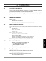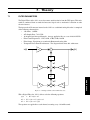
1
Model 3411 Torque Display User’s Manual Purchase Record Please record all model numbers and serial numbers of your Magtrol equipment, along with the general purchase information. The model number and serial number can be found on either a silver identification plate or white label affixed to each unit. Refer to these numbers whenever you communicate with a Magtrol representative about this equipment. Model Number: _____________________________ Serial Number: _____________________________ Purchase Date: _____________________________ Purchased From: _____________________________ While every precaution has been exercised in the compilation of this document to ensure the accuracy of its contents, Magtrol, Inc. assumes no responsibility for errors or omissions. Additionally, no liability is assumed for any damages that may result from the use of the information contained within this publication. Copyright Copyright ©2013-2014 Magtrol, Inc. All rights reserved. Copying or reproduction of all or any part of the contents of this manual without the express permission of Magtrol is strictly prohibited. Trademarks LabVIEW™ is a trademark of National Instruments Corporation. National Instruments™ is a trademark of National Instruments Corporation. Windows® is a registered trademark of Microsoft Corporation. First Edition rev C – September 2014 Safety Precautions 1. Make sure that all Magtrol Torque Transducers and electronic products are earth-grounded, to ensure personal safety and proper operation. 2. Make sure that torque transducers and motors under test are equipped with appropriate safety guards. i Revisions To This Manual The contents of this manual are subject to change without prior notice. Should revisions be necessary, updates to all Magtrol User’s Manuals can be found at Magtrol’s web site at www.magtrol.com/support/manuals.htm. Please compare the date of this manual with the revision date on the web site, then refer to the manual’s Table of Revisions for any changes/updates that have been made since this edition. Revision Date First Edition rev C – September 2014 Table of Revisions Date Edition Change Section(s) 09/12/14 1st. Edition - rev C LAN Setup Commands updated. 5.3.3 07/28/14 1st. Edition - rev B Chapter 7 - Theory added to manual. Chapter 7 03/10/14 1st. Edition - rev A 3411 Block Diagram updated. A.1 ii Table of Contents Safety Precautions..........................................................................................................................i Revisions To This Manual................................................................................................................ii Revision Date..................................................................................................................................................................ii Table of Revisions.......................................................................................................................................................ii Table of Contents...........................................................................................................................iii Preface................................................................................................................................................. v Purpose of This Manual.......................................................................................................................................... v Who Should Use This Manual............................................................................................................................... v Manual Organization.............................................................................................................................................. v Conventions Used in This Manual.................................................................................................................... vi 1. Introduction.................................................................................................................................1 1.1 Unpacking Your 3411 Torque Display.......................................................................................................... 1 1.2 Features of the 3411 Torque Display.......................................................................................................... 1 1.3 Data Sheet................................................................................................................................................................. 3 2. Controls..........................................................................................................................................6 2.1 Front Panel.............................................................................................................................................................. 6 2.2 Rear Panel................................................................................................................................................................ 8 2.2.1 Rear Panel Inputs and Outputs...................................................................................................... 8 3. Installation/Configuration...................................................................................................10 3.1 Powering up the 3411......................................................................................................................................... 10 3.1.1 Line Voltage............................................................................................................................................ 10 3.1.2Self-Test................................................................................................................................................... 10 3.1.3 Main Menu................................................................................................................................................ 11 4. Manually Controlled Operation........................................................................................12 4.1 Setting Desired Operating Parameters................................................................................................. 12 4.1.1 Torque Scale Setup............................................................................................................................. 12 4.1.2 Pulse Per Rev Setup............................................................................................................................. 12 4.1.3 Display Units Setup............................................................................................................................. 12 4.1.4 Power Units Setup................................................................................................................................ 13 4.1.5 System Setup........................................................................................................................................... 13 5. Computer Controlled Operation.......................................................................................18 5.1 About the Ethernet Interface................................................................................................................... 18 5.2 About the USB Interface................................................................................................................................ 20 5.2.1 USB Driver Setup for WindowsXP/Windows7 32BIT.............................................................. 20 5.2.2 USB Driver Setup for Windows7/8 64BIT..................................................................................... 22 5.2.3 Set up USB communication.............................................................................................................. 22 5.3 3411 Command Set................................................................................................................................................ 22 5.3.1 Communication Commands............................................................................................................. 23 5.3.2 Setup Commands................................................................................................................................... 24 5.3.3 LAN Setup Commands.......................................................................................................................... 25 iii Table of Contents Magtrol Model 3411 Torque Display 5.4 Calibration and Miscellaneous Commands......................................................................... 26 5.5Output Binary Table......................................................................................................................................... 27 6. Calibration...................................................................................................................................28 6.1 Closed-Box Calibration................................................................................................................................. 28 6.2 Calibration Schedule...................................................................................................................................... 28 6.3Basic Calibration Process............................................................................................................................. 28 6.3.1 Initial Calibration Procedure..................................................................................................... 28 6.3.2 Torque Offset and Gain.................................................................................................................... 28 6.3.3 Speed DAC Calibration....................................................................................................................... 29 6.3.4 Frequency Gain..................................................................................................................................... 29 7. Theory.............................................................................................................................................31 7.1 Filter Parameters ............................................................................................................................................. 31 8. Troubleshooting........................................................................................................................32 Appendix A: Schematics.................................................................................................................33 A.13411 Schematic...................................................................................................................................................... 33 Appendix B: Menu Structure.......................................................................................................34 B.1 3411 Menu structure......................................................................................................................................... 34 Service Information.......................................................................................................................36 Returning Magtrol equipment for Repair and/or Calibration...................................................... 36 Returning Equipment to Magtrol, Inc. (United States)................................................................. 36 Returning Equipment to Magtrol SA (Switzerland)...................................................................... 36 iv Table of Contents Magtrol Model 3411 Torque Display Table of Figures 2. Controls Figure 2–1 Figure 2–2 Figure 2–3 Figure 2–4 Figure 2–5 Front Panel................................................................................................................................................6 Rear Panel.................................................................................................................................................8 Ethernet Connector...................................................................................................................................8 USB Connector..........................................................................................................................................8 Transducer Connector...............................................................................................................................9 3. Installation/Configuration Figure 3–1 Figure 3–2 Figure 3–3 Figure 3–4 Cable and Connection Diagrams............................................................................................................10 Title Display 1 (up to 1 minute)...............................................................................................................11 Title Display 2 (5 seconds)......................................................................................................................11 Main Menu..............................................................................................................................................11 4. Manually Controlled Operation Figure 4–1 Torque Scale Setup..................................................................................................................................12 Figure 4–2 Pulse per Rev. Setup................................................................................................................................12 Figure 4–3 Display Units Setup.................................................................................................................................13 Figure 4–4 Power Units Setup...................................................................................................................................13 Figure 4–5 BITE Setup...............................................................................................................................................14 Figure 4–6 User Setup...............................................................................................................................................14 Figure 4–7 IP Address View.......................................................................................................................................15 Figure 4–8 Filter Selection Setup..............................................................................................................................15 Figure 4–9 Contrast Setup.........................................................................................................................................15 Figure 4–10 Analog Speed BNC Output Setup..........................................................................................................16 Figure 4–11 TM Invert Setup.....................................................................................................................................17 5. Computer Controlled Operation Figure 5–1 Figure 5–2 Figure 5–3 Figure 5–4 Figure 5–2 Figure 5–3 Figure 5–4 Figure 5–5 Authentification Window..........................................................................................................................18 Magtrol 3411 home web page.................................................................................................................18 Network Settings web page......................................................................................................................19 Torque Display Input web page...............................................................................................................19 Driver Installation Window.....................................................................................................................20 Installation Options Window...................................................................................................................21 Installation Finish Window......................................................................................................................21 Installation Complete Window................................................................................................................22 7. Theory Figure 7–1 Transposed Direct Form II Architecture..................................................................................................31 v Preface Purpose of This Manual This manual contains all the information required for the installation and general use of the Model 3411 Torque Display. To achieve maximum capability and ensure proper use of the instrument, please read this manual in its entirety before operating. Keep the manual in a safe place for quick reference whenever a question should arise. Who Should Use This Manual This manual is intended for bench test operators who are going to use the 3411 Torque Display in conjunction with any Magtrol TM In-Line Torque Transducer and TF Torque Flange Sesnor. Manual Organization This section gives an overview of the structure of the manual and the information contained within it. Some information has been deliberately repeated in different sections of the document to minimize cross-referencing and to facilitate understanding through reiteration. The structure of the manual is as follows: Chapter 1: Introduction - Contains the technical data sheet for the 3411 Torque Transducer Display, which describes the unit and provides its mechanical and electrical characteristics. Chapter 2: CONTROLS - Description of the elements located on the front and rear panels of the unit. Chapter 3: Installation/Configuration - Provides information needed for setup of the 3411. Chapter 4: Manually Controlled Operation - How to run a test when the 3411 is used as a stand-alone unit. Chapter 5: Computer Controlled Operation - How to run a test when the 3411 is used with a personal computer. Includes information on the USB and Ethernet interfaces and command set. Chapter 6: Calibration - Provides recommended calibration schedules along with stepby-step instructions for the calibration procedure. Chapter 7: THEORY Chapter 8: Troubleshooting - Solutions to common problems encountered during setup and testing. Appendix A: Schematics - For the 3411 Display. Appendix B: MENU SELECTION - Menu selection diagram. vi Preface Magtrol Model 3411 Torque Display Conventions Used in This Manual The following symbols and type styles may be used in this manual to highlight certain parts of the text: Note: This is intended to draw the operator’s attention to complementary information or advice relating to the subject being treated. It introduces information enabling the correct and optimal functioning of the product to be obtained. Caution:This is used to draw the operator’s attention to information, directives, procedures, etc. which, if ignored, may result in damage being caused to the material being used. The associated text describes the necessary precautions to take and the consequences that may arise if the precautions are ignored. WARNING! This introduces directives, procedures, precautionary measures, etc. which must be executed or followed with the utmost care and attention, otherwise the personal safety of the operator or third party may be put at risk. The reader must absolutely take note of the accompanying text, and act upon it, before proceeding further. vii 1.1 Introduction Unpacking Your 3411 Torque Display Your 3411 Torque Display was packaged in reusable, shock resistant packing material that will protect the instrument during normal handling. 1. Make sure the carton contains the following: Line cord 3411 Torque Display Magtrol User Manual CD-Rom Torque 7 Data Acquisition Software USB Cable Calibration Certificate 2. Inspect the contents for any evidence of damage in shipping. In the event of shipping damage, immediately notify the carrier and Magtrol’s Customer Service Department. 1.2 Note: Save all shipping cartons and packaging material for reuse when returning the instrument for calibration or servicing. Features of the 3411 Torque Display Designed specifically for use with Magtrol’s TM In-Line Torque Transducers and TF Torque Flange Sensors, the Model 3411 Torque Display powers the transducer and utilizes high-speed digital signal processing to display torque, speed and mechanical power. Its features include: • High Quality, Easy-to-Read Display: Vacuum fluorescent readout. • Addition of high resolution quadrature encoder enable slow RPM applications or position measurements • Selectable English, Metric and SI Torque Units • Isolated USB Interface • Ethernet connectivity 1 GENERAL INFORMATION 1. Chapter 1 – Introduction Torque: Analog, raw sensor output Speed output; analog or digital, user selectable BITE: Built-In Test Equipment Overload Indication Tare Function High Speed Data Acquisition: Up to 500 torque and speed points per second with time stamp Rack mount or handle versions available 2 GENERAL INFORMATION • • • • • • • Magtrol Model 3411 Torque Display Chapter 1 – Introduction Magtrol Model 3411 Torque Display Data Sheet MAGTROL 3411 Data Sheet Model 3411 Torque Display FEATURES • • • • • • • • • • • • • • ForusewithallMagtrolTM/TMHS/TMBIn-Line TorqueTransducersandTFTorqueFlangeSensors HighQuality,Easy-to-ReadVacuumFluorescent Readout:Displaystorque,speedandpower Additionofhighresolutionquadratureencoderenables lowRPMapplicationsorpositionmeasurements SelectableEnglish,MetricandSITorqueUnits IsolatedUSBInterface Ethernetconnectivity Torque:Analog,rawsensoroutput Speedoutput;analogordigital,userselectable BITE:Built-InTestEquipment OverloadIndication TareFunction IncludesMagtrolTorque7Software HighSpeedDataAcquisition:Upto500torqueand speedpointspersecondwithtimestamp Rackmountorhandleversionsavailable TORQUE 7 SOFTWARE Magtrol’s Torque 7 Software is a user-friendly LabView® executableprogram,usedtoautomaticallycollecttorque,speed andmechanicalpowerdata.Thedatacanbeprinted,displayed graphicallyorquicklysavedasaMicrosoft®Excelspreadsheet. StandardfeaturesofTorque7include: • MeasuredParametervs.Time • AdjustableSamplingRates • PolynomialCurveFitting • PeakTorqueCapture • DirectionofRotation • Multi-AxesGraphing • OptionalUSBInterface:forreadingupto4thermocouples DESCRIPTION Magtrol’sModel3411TorqueDisplayisdesignedforusewith allMagtrolTM,TMHS,TMBandTFTorqueTransducers. This easy-to-use device powers the transducer and utilizes highspeedprocessingtodisplaytorque,speedandmechanical power.Itincludesatarefunctiontohelpoffsetanyslight residuals caused by couplings or suspended loads. The 3411mayalsobeusedwithanytorquesensorsrequiring24 VDC power (500 mA max.) with ±5VDC torque output (±10VDCmax.)andopencollector,TTLorCMOSoutput forthespeedsignal. SYSTEM CONFIGURATION TF Torque Flange Sensor Receiver PC Torque 7 Software – OR – MODEL 3411 TORQUE DISPLAY TM, TMHS or TMB Series In-Line Torque Transducer www.magtrol.com 1 3 GENERAL INFORMATION 1.3 Chapter 1 – Introduction Magtrol Model 3411 Torque Display 3411 MEASUREMENT CHARACTERISTICS Maximum Speed / 199,999 rpm / 199,999 Hz Input Frequency Speed: 0.01% of reading from Accuracy 5 rpm to 199,999 rpm Torque: 0.02% of range (± 10 V) ELECTRICAL CHARACTERISTICS Fuses (5 × 20 mm) IEC 500 mA 250 V T Power Requirements 36 VA Voltage Requirements 120/240 V 60/50 Hz INPUTS AND OUTPUTS Speed/Angle: Open Collector, 5 V HC, Transducer Inputs TTL, CMOS Torque: ± 10 V DC max Torque Output BNC ±10 V DC (direct from transducer) 5 V HC pulse (buffered from transducer) or Speed Output BNC +/- 10 VDC analog * Sensor power available at 14 pin connector: 5 VDC 200 ma, fused internally at 500 ma 24 VDC 500 ma, short circuit protected ENVIRONMENT Operating Temperature 5 ºC to 50 ºC Relative Humidity < 80% Temperature Coefficient 0.001% (5 ºC to 50 ºC) of FS/ºC DIMENSIONS Width 10.14 in 257.5 mm Height 4.05 in 103 mm Depth 10.80 in 274.3 mm Weight 5.11 lb 2.32 kg FRONT PANEL Displays Torque, Speed and Mechanical Power Values Torque Scale xx.xx N·m / 5V Pulse Per Revolution 1 to 99,999 Power Units W, kW, HP System Setup Tare Reset Tare Display Units Oz·in, Oz·ft, Lb·in, Lb·ft, g·cm, kg·cm, mN·m, cN·m, N·m, daN·m 4 2 MAGTROL GENERAL INFORMATION Specifications Chapter 1 – Introduction Magtrol Model 3411 Torque Display GENERAL INFORMATION Ordering Information 3411 REAR PANEL Torque Output Speed Output USB connection Transducer connection For Use With Any Magtrol TM, TMHS,TMB or TF Torque Transducer (or other brand torque sensor) Ethernet connection ACCESSORIES Description TM / TMHS / TMB In-Line Torque Transducer Connector Cable, 5 m TM / TMHS / TMB In-Line Torque Transducer Connector Cable, 10 m TM / TMHS / TMB In-Line Torque Transducer Connector Cable, 20m TF Flange Torque Transducer Connector Cable, 5 m TF Flange Torque Transducer Connector Cable, 10 m TF Flange Torque Transducer Connector Cable, 20m SBB-14 for optional high resolution encoder attachment Model # ER 113/01 ER 113/02 ER 113/03 ER 116/01 ER 116/02 ER 116/03 SBB-14 ORDERING INFORMATION Description Torque Display Torque Display with Handle Torque Display with Rack Mount Model/Part # 3411 3411-HDL 3411-RMK Stock Code 006862 007017 007015 Due to the continual development of our products, we reserve the right to modify specifications without forewarning. MAGTROL INC 70 Gardenville Parkway Buffalo, New York 14224 USA Phone: +1 716 668 5555 Fax: +1 716 668 8705 E-mail: [email protected] MAGTROL SA Route de Montena 77 1728 Rossens / Fribourg, Switzerland Phone: +41 (0)26 407 5 3000 Fax: +41 (0)26 407 3001 E-mail: [email protected] Subsidiaries in: Germany • France China • India Worldwide Network of Sales Agents 3411-US 08/13 www.magtrol.com 2.1 Front Panel The front panel contains a Vacuum Fluorescent Display (VFD) that provides information about the control functions and torque transduce. Figure 2–1 Front Panel The buttons from left to right, top to bottom are: • POWER SWITCH • UP • DOWN • LEFT • RIGHT • ENTER • TORQUE SCALE • PULSE PER REV • DISPLAY UNITS • POWER UNITS • SYSTEM SETUP • TARE • RESET TARE The following table provides a quick reference on how to use each button. For more detailed information refer to Chapter 4 – Manually Controlled Operation. Button POWER SWITCH To Use Press I to turn power ON. Press O to turn power OFF. UP Press. DOWN Press. LEFT Press. Function Turns power ON or OFF. The UP button will scroll up through the possible selections. The UP button will increase the number under the cursor. The DOWN button will scroll down through the possible selections. The DOWN button will decrease the number under the cursor. Moves the cursor left. 6 GENERAL INFORMATION 2. Controls Chapter 2 – Controls Magtrol Model 3411 Torque Display To Use Function Moves the cursor right. Accepts current selection. xx.xx N·m/5 V Use TORQUE SCALE to enter the rated torque of the attached transducer. Press. Press. TORQUE SCALE Press. PULSE PER REV Press. DISPLAY UNITS Press. POWER UNITS Press. SYSTEM SETUP Press. TARE Press. Encoder pulse per revolution input to 99,999. Press and then use the UP/DOWN buttons to scroll through the possible selections. Press ENTER to select the desired display unit. • oz·in • oz·ft • lb·in • lb·ft • g·cm • kg·cm • mN·m • cN·m • N·m • daN·m Press and then use the UP/DOWN buttons to scroll through the possible selections. Press ENTER to select the desired power unit. • hp • W • kW Press and then use the UP/DOWN buttons to scroll through the possible selections. Press ENTER to select the desired system setup. • BITE • USER SETUP • STATIC IP SET • DHCP ADDRESS VIEW • FILTER SETUP • CONTRAST • SPEED BNC OUTPUT • TM INVERT • RETURN Sets the current A/D reading as the offset value during calculations of torque. Resets the TARE to the calibrated offset A/D reading value for calculations of torque. RESET TARE Press. 7 GENERAL INFORMATION Button RIGHT ENTER Chapter 2 – Controls Rear Panel The rear panel provides connectors and receptacles for connecting to appropriate equipment. Figure 2–2 Rear Panel 2.2.1 Rear Panel Inputs and Outputs ETHERNET Attach Ethernet cable here. Figure 2–3 Ethernet Connector USB Isolated USB Connector Figure 2–4 USB Connector Torque Output Attach Torque Output cable here Speed Output Attach Speed Output cable here 8 GENERAL INFORMATION 2.2 Magtrol Model 3411 Torque Display Chapter 2 – Controls Magtrol Model 3411 Torque Display Connect transducer signal cable here. 7 6 5 4 3 2 1 14 13 12 11 10 9 8 1. N/C 2. TACH B 3. +24 VDC 4. +24 VDC COM 5. +24 VDC COM 6. N/C 7. 5 V OUT 8. 9. 10. 11. 12. 13. 14. 5 V COM N/C TACH A N/C BITE TORQUE COMMON TORQUE SIGNAL Figure 2–5 Transducer Connector POWER Attach IEC approved power cord here. 9 GENERAL INFORMATION TRANSDUCER 3. Installation/Configuration 3.1 Powering up the 3411 Note: To reduce the risk of electric shock, the case of the 3411 is earth grounded. Line Voltage The 3411 will operate with either of the following power sources without any modifications: • 120 V 50/60 Hz • 230 V 50/60 Hz 3.1.2 Self-Test Note: To make sure that the 3411 is operational, a Magtrol torque sensor must be installed and connected to the 3411. 1. Connect the 3411 to the torque transducer using a 14-pin to 6-pin signal cable. Figure 3–1 Cable and Connection Diagrams 10 SETUP 3.1.1 Note:Before installing the 3411, you should become familiar with the front and rear panels, as outlined in Chapter 2–Controls. Chapter 3 – Installation/Configuration Magtrol Model 3411 Torque Display 2. Turn on the power to the 3411. The Title Displays will appear. POWER TORQUE SPEED MAGTROL 3411 Figure 3–2 Title Display 1 (up to 1 minute) TORQUE FW REVXX SPEED FPGA REVXX Figure 3–3 Title Display 2 (5 seconds) 3.1.3 Main Menu When the 3411 is completely powered up and ready for use, the Main Menu will appear on the dispay. POWER TORQUE 0.000 +0.000 Figure 3–4 Main Menu 11 SPEED 0 SETUP POWER 4. Manually Controlled Operation 4.1 Setting Desired Operating Parameters 4.1.1Torque Scale Setup Selects the Torque Scale for the 3411 Display. 1. Press and release TORQUE SCALE button. The display will appear as follows: POWER TORQUE SPEED Nm/5V XXXXXX Figure 4–1 Torque Scale Setup 2. Press and release the arrow buttons until desired torque scale appears in display. 3. Press and release ENTER button to save and return to the Main Menu. 4.1.2Pulse Per Rev Setup Selects the Pulse per Rev for the 3411 Display. 1. Press and release PULSE PER REV button. The display will appear as follows: TORQUE SPEED PULSE/REV XXXXX Figure 4–2 Pulse per Rev. Setup 2. Press and release the arrow buttons until desired pulse per rev appears in display. 3. Press and release ENTER button to save and return to the Main Menu. 4.1.3 Display Units Setup Selects the desired unit of measure that corresponds with the values displayed. Options include: • oz·in • mN·m • oz·ft • cN·m • lb·in • N·m • lb·ft • kN·m • g·cm • daN·m • kg·cm 12 OPERATION POWER Chapter 4 – Manually Controlled Operation Magtrol Model 3411 Torque Display 1. Press and release DISPLAY UNITS button. The display will appear as follows: POWER TORQUE SPEED XX.XX Figure 4–3 Display Units Setup 2. Press and release the UP/DOWN arrow buttons until desired display unit appears in display. 3. Press and release ENTER button to save and return to the Main Menu. 4.1.4 Power Units Setup Selects the desired unit of power that corresponds with the values displayed. Options include: • Watts • kW • hp 1. Press and release POWER UNITS button. The display will appear as follows: POWER TORQUE SPEED XX 2. Press and release the UP/DOWN arrow buttons until desired power unit appears in display. 3. Press and release ENTER button to save and return to the Main Menu. 4.1.5 System Setup Selects the display options for the 3411 Display. Options include: • BITE • USER SETUP • IP ADDRESS VIEW • FILTER SELECTION • CONTRAST • SPEED BNC OUTPUT • TM INVERT • RETURN 1. Press and release SYSTEM SETUP button. 2. Press and release the UP/DOWN arrow buttons until desired setup option appears in display. 3. Press and release ENTER to go to the setup menu for that option. 13 OPERATION Figure 4–4 Power Units Setup Chapter 4 – Manually Controlled Operation Magtrol Model 3411 Torque Display 4.1.5.1BITE Built-In Test Equipment (BITE) has been programmed into the 3411 in order to test the system and make sure all devices are connected and running properly. When the BITE function is activated the software will turn on an NPN transistor internal to the 3411 that is in an open collector configuration. This output, or collector, is found on pin 12 of the 14-pin connector on the back of the unit. This signal is routed to the transducer and will activate internal circuitry to output a test signal. In the case of a TM series transducer, the output will be 5 volts (full scale) in addition to any offset value. As for the TF series, the output will be about 4 volts (about 80% of full scale) in addition to any offset value. 1. Press and release SYSTEM SETUP button. 2. Press and release UP/DOWN arrow buttons until BITE shows in the display. 3. Press and release ENTER. The BITE function will acitvate for 5 seconds and then reutrn to the Main Menu. The display will appear as follows while the BITE function is activated: POWER TORQUE BITE = SPEED X.XXX Figure 4–5 BITE Setup 4.1.5.2User Setup POWER TORQUE SPEED USER SETUP #X Figure 4–6 User Setup 5. Press and release ENTER to select the user setup and return to the Main Menu. 4.1.5.3IP Address View 1. Press and release SYSTEM SETUP button. 2. Press and release UP/DOWN arrow buttons until IP ADDRESS VIEW shows in the display. 3. Press and release ENTER to view the 3411 Display’s IP Address. The display will appear as follows: 14 OPERATION The 3411 Display allows 4 user setup configurations to be saved on the device. 1. Press and release SYSTEM SETUP button. 2. Press and release UP/DOWN arrow buttons until USER SETUP shows in the display. 3. Press and release ENTER to go to the user setup menu. 4. Press and release UP/DOWN arrow buttons until the desired user setup number appears in the display. The display will appear as follows: Chapter 4 – Manually Controlled Operation Magtrol Model 3411 Torque Display POWER TORQUE SPEED XXX.XXX.XX.XXX Figure 4–7 IP Address View 4.1.5.4Filter Selection Setup Sets the desired Filter Selection for the 3411 Display. The options include: • None • 20 Hz • 2 Hz • 50 Hz • 5 Hz • 100 Hz • 10 Hz 1. Press and release SYSTEM SETUP button. 2. Press and release UP/DOWN arrow buttons until FILTER SELECTION shows in the display. 3. Press and release ENTER to go to the filter selection setup menu. The display will appear as follows: POWER TORQUE SPEED XX HZ 4. Press and release the UP/DOWN arrow buttons until the desired filter selection appears in the display. 5. Press and release ENTER to save and return to the Main Menu. 4.1.5.5Contrast The 3411 is shipped with the Contrast programmed to the lowest setting in order to prolong display life. If it is necessary to increase the Contrast for improved readability, execute the following steps: 1. Press and release SYSTEM SETUP button. 2. Press and release UP/DOWN arrow buttons until CONTRAST shows in the display. 3. Press and release ENTER to go to the contrast setup menu. Display will appear as follows: POWER TORQUE X Figure 4–9 Contrast Setup 15 SPEED OPERATION Figure 4–8 Filter Selection Setup Chapter 4 – Manually Controlled Operation Magtrol Model 3411 Torque Display 4. Press and release UP/DOWN arrow buttons until the desired contrast setting shows in the display. 5. Press and release ENTER to save and return to the Main Menu. 4.1.5.6Speed BNC Output Setup 1. Press and release SYSTEM SETUP button. 2. Press and release UP/DOWN arrow buttons until SPEED BNC OUTPUT shows in the display. 3. Press and release ENTER to go to the speed BNC output setup menu. 4. Press and release UP/DOWN arrow buttons until desired speed BNC output is shown in the display. 5. Press and release ENTER to select. If you selected Digital the setup is complete and the display will return to the Main Menu. If you selected analog the display will appear as follows: POWER TORQUE XXXXXX SPEED RPM/V Figure 4–10 Analog Speed BNC Output Setup 6. Press and release the arrow buttons until the desired speed BNC output appears in the display. 7. Press and release ENTER to save and return to the Main Menu. OPERATION 16 Chapter 4 – Manually Controlled Operation Magtrol Model 3411 Torque Display 4.1.5.7TM Invert Setup 1. Press and release SYSTEM SETUP button. 2. Press and release UP/DOWN arrow buttons until TM INVERT shows in the display. 3. Press and release ENTER to go to the TM invert setup menu. The display will appear as follows: POWER TORQUE SPEED XXX Figure 4–11 TM Invert Setup 4. Press and release the UP/DOWN arrow buttons until the desired TM invert selection appears in the display. 5. Press and release ENTER to save and return to the Main Menu. 4.1.6 Tare Function The calibrated offset of the 3411 may be changed using the tare function. To set: 1. Press TARE button. 2. The red LED light will turn on and the unit will take the current value of the torque input and make it the new zero. Note: In order to reset the tare value, press and release RESET TARE button. OPERATION 17 5. Computer Controlled Operation The 3411 Torque Display can be used with a personal computer for standard or custom torque and encoder setups. Using the 3411 with a computer enables the unit to perform at its full capacity. 5.1 About the Ethernet Interface Connect one Ethernet cable terminal to 3411 RJ45 interface, and another terminal to Ethernet RJ45 on wall outlet or Ethernet switch. Reference 4.1.5.4, dynamic IP address will show, for example, 192.168,14,88. Launch windows internet explorer, type http://192.168.14.88. The following authentication page will pop up. The default Authentication Username is “admin”. There is no Authentication Password. Figure 5–1 Authentification Window Figure 5–2 Magtrol 3411 home web page Press “Network”to display the LAN settings. 18 OPERATION After the user name “admin” is entered, press “OK” button, the 3411 home web page will display. Chapter 5 – Computer Controlled Operation Magtrol Model 3411 Torque Display Press key, to return to the home web page. Figure 5–3 Network Settings web page In the home web page, press “TSP” to display the torque, speed and power web page. Select the “Periodic” check box so that Power, torque, and speed values will refresh at 0.5S intervals. Press key, it will return home web page. OPERATION Figure 5–4 Torque Display Input web page NOTE:Background checking for Ethernet connection could last up to 1 minute after power on to obtain a DHCP IP address. 19 Chapter 5 – Computer Controlled Operation NOTE: Magtrol Model 3411 Torque Display Ethernet communication will be lost during key entry into front panel menus after 2 minutes. 5.2About the USB Interface The USB interface is standard on the 3411 Torque Display. There is a need to set this up. The USB interface will be converted to a serial port in the PC. The USB driver must be installed in order for the 3411 to communicate with the PC. 5.2.1 USB Driver Setup for WindowsXP/Windows7 32BIT Copy the 3411 USB driver files from the Magtrol Manual CD at programs\3411USB Driver\ directory into local drive of your PC. 1. Run CP210xVCPInstaller_x86.exe. 2. Power on the 3411. The Found New Hardware Wizard window will pop up as shown below. On the Driver Installation window choose “Install from a list or specific location (Advanced)” option as shown in figure 5–1 Driver Installation window. OPERATION Figure 5–2 Driver Installation Window 3. Click the Next button. The following screen will display. Browse for the location “C:\ 3411 USB Driver\”. 20 Chapter 5 – Computer Controlled Operation Magtrol Model 3411 Torque Display Figure 5–3 Installation Options Window 4. Click the Next button. The following screen will display. The driver will be installed. OPERATION Figure 5–4 Installation Finish Window 5. Click Finish button, “Found new hardware” will show in right corner. Then USB driver has been installed correctly. 21 Chapter 5 – Computer Controlled Operation Magtrol Model 3411 Torque Display Figure 5–5 Installation Complete Window 5.2.2 USB Driver Setup for Windows7/8 64BIT Copy the 3411 USB driver files from the Magtrol Manual CD at programs\3411USB Driver\ directory into local drive of your PC. 1. Run CP210xVCPInstaller_x64.exe. 2. Power on the 3411. A window in the right corner will show “Installing device driver software” and then show “Magtrol 3411 CP210x USB to UART Bridge(COM#)”. Set up USB communication 5.2.3.1 Communication Parameters • No parity • 8 data bits • 1 stop bit • No protocol 5.2.3.2 Baud Rate The application in PC should set up baud rate 921600 in order to communicate with PC via USB. 5.3 3411 Command Set When entering a command code: 1. Type all characters in uppercase ASCII format. 2. End all commands with a CR-LF (hex 0D-0A). 3. Do not string multiple commands together in one line. The character # represents a floating-point numerical value following the command. Leading zeroes are not required. Note: If a command is not recognized, a COMMAND ERROR CR-LF string return will occur. 22 OPERATION 5.2.3 Chapter 5 – Computer Controlled Operation Magtrol Model 3411 Torque Display 5.3.1 Communication Commands Command Code *IDN? Function Explanation Returns Magtrol identification and software revision. Prompts to return speedtorque-direction data string. OP Reads quadrature position OS Reads speed OV Reads voltage QR Reset position counter OB Output Binary Data BITE Activates BITE for 5 seconds 23 Output Data prompt to return data string with this format: SxxxxxxTxxxxxRcrlf or SxxxxxxTxxxxxLcrlf R or L are used to indicate the polarity of the torque and may be used as a shaft direction indicator where: 1. With TM INVERT off: R will indicate positive L will indicate negative The speed will equal the displayed value and the torque will be in the same units as displayed on the front panel. Quadrature position counter returns data string with 8 digit hex number. Read speed with four decimal digits. Reads voltage applied to Torque input mV. Output sign follows the TM INVERT setting. Resets the position counter to zero at current position. Quadrature Timer is not reset User can read up to 8 words data at a rate of 500 times per second . Please refer Output Binary table. Built In Test Equipment command. OPERATION OD Example: 3411 A0 B0 Chapter 5 – Computer Controlled Operation 5.3.2 Magtrol Model 3411 Torque Display Setup Commands Command Code Function Explanation Sets filter M0 M1 Front panel lockout Front Panel enable SPS# Speed selection SPSFxx.xx TR TS Analog speed scale factor Resets Tare Sets Tare. UE# Sets encoder units to # UP# Sets the Power Units. UR# Sets display torque units to #. UT# Sets torque scale to # INVERT# Negates the incoming Voltage (Torque signal) USER# Selects configuration number SAVE Save set up 24 OPERATION AF# Values for # are: 0 = None 4 = 20 Hz 1 = 2 Hz 5 = 50 Hz 2 = 5 Hz 6 = 100 Hz 3 = 10 Hz Front panel lockout, keys will not function. Front Panel enable, keys will function. Values for # are: 0 = Digital TachA output on pack panel BNC 1 = Analog speed output on pack panel BNC Values for xx.xx range from 1 to 999,999. Resets tare to calibrated 0 (zero). Reads current torque and uses as tare value. Values for # range from 1 to 99999 Values for # are: 0 = hp 1=W 2 = kW Values for # are: 0 = oz•in 6 = mN•m 1 = oz•ft 7 = cN•m 2 = lb•in 8 = N•m 3 = lb•ft 9 = kN•m 4 = g•cm 10 = daN•m 5 = kg•cm Torque unit conversion defaults to Nm if out of range. Values for # range from 0.01 to 999999 Values for # 0 Non Inverted (default value) 1 Inverted Values for # 1,2,3,4 NOTE: If a USER SETUP is changed via the USB or Ethernet it is volatile until SAVE command is sent. Save set up to current user configuration Chapter 5 – Computer Controlled Operation Magtrol Model 3411 Torque Display 5.3.3 LAN Setup Commands Function Enables/Disables DHCP use. You must send the “UPD” command after sending DHCP# for the change to take place. When disabling DHCP, you must also set a static ip, a gateway and a subnet netmask prior to sending the “UPD” command. Contact your network administrator for the appropriate network settings. Explanation Values for # are: 1 = Enable 0 = Disable DHCP? Read current DHCP state Return #: 1 = Enable 0 = Disable IPAD, XXX.XXX.XXX If DHCP is enabled, setting the static Sets the static ip address. ip address has no effect. Contact your You must send the “UPD” command after “IPAD,xxx.xxx. network administrator for details. xxx.xxx” for the new setting to take effect. IPAD? Read current IP address Typical Return: 192.168. 14. 35 GATEWAY, XXX.XXX.XXX.XXX Sets the gateway address used. You must send the “UPD” command after “GATEWAY,xxx.xxx.xxx.xxx” for the new setting to take effect. If DHCP is enabled, setting the gateway address has no effect. Contact your network administrator for details. GATEWAY? Read current default gateway address Typical Return: 192.168. 14. 1 HOST? Read current local host name Typical return: M34110001 MAC? Read MAC address Typical return: 02AA00000002 SMAS, XXX.XXX.XXX.XXX Sets the subnet netmask. You must send the “UPD” command after “SMAS,xxx. xxx.xxx.xxx” for the new setting to take effect. If DHCP is enabled, setting the netmask has no effect. Contact your network administrator for details. SMAS? Read current subnet mask Typical return: 255.255.255.0 UPD Saves all LAN settings to non- To disable DHCP, the static ip, volatile memory and activates gateway, and netmask commands them. must have been given prior to sending “UPD”. If DHCP is already disabled, “UPD” may be used to change a single static network setting, i.e. only the netmask, or only the gateway. Contact your network administrator for details. 25 OPERATION Command Code DHCP# Chapter 5 – Computer Controlled Operation Command Code WHOST, XXXXXXXXXXXXXXX 5.4 Magtrol Model 3411 Torque Display Function Save new local host name to non-volatile memory and activate new host name Explanation xxxxxxxxxxxxxxx: String of up to 15 characters. Must start with letter (A-Z) May contain letters, numbers (0-9), or dashes (“-”) Calibration and Miscellaneous Commands Command Code MODE# Function Explanation Values for # 0 User 1 Calibration/engineering User/Calibration mode MODE 1 COMMANDS INIT Reset to factory defaults IOAOX.XXX Write the value to DAC CAL ZERO FN=X.XXX CALS FREQ= X.XXX CALDAC OV SPS# Response is FS=X.XXX prompting the user to apply Full Scale User enters X.XXX (meter reading) Response is FN=-X.XXX User enters X.XXX (meter reading) Response is CAL COMPLETE Response is FREQ=XXXXX.XX prompting the user to apply frequency User enters X.XXX (meter reading) in Hz Response is CAL COMPLETE Response is READ ZERO User enters X.XXX (meter reading) Response is ZERO OK? Command to accept DAC zero Response is FSDAC=X.XXX Command to set the Positive User enters X.XXX (meter reading) Full Scale (gain) Response is FS OK? Command to accept DAC gain Response is CAL COMPDAC Reads voltage applied to Torque input mV. Reads Voltage Output sign follows the TM INVERT setting. Values for # are: Speed selection 0 = Digital TachA output on pack panel BNC 1 = Analog speed output on pack panel BNC ZDAC=X.XXX Command to set applied zero ZERO OK FSDAC= X.XXX FS OK Response is ZERO 26 OPERATION FS=X.XXX Command to start A/D Calibration Command to accept applied zero Command to set the Positive Full Scale (gain) Command to set the Negative Full Scale (gain) Command to start frequency Calibration Command to set the frequency correction Command to start DAC Calibration Caution calibration will be lost. *POWER cycle required after the command. Write the value to the Speed DAC. Volts are assumed. X.XXX floating point voltage value 3 decimal places +10.000 to -10.000 Chapter 5 – Computer Controlled Operation Magtrol Model 3411 Torque Display 5.5Output Binary Table Number Data Description Data Type 0 TimeH Time stamp: the first 32 bit value Integer 1 TimeL Time stamp: the last 32 bit value Integer 2 Display speed Speed derived by using a 0.2 second gate (slow) Display value Float 3 Torque display Torque derived by using a heavily average (slow) Display value Float 4 Quadrature counter Quadrature Position counter Integer 5. Quadrature time Quadrature Position Time Integer 6 Speed Speed derived by using an averaged time between edges. (fast) Float 7 Torque Torque value “2 ms” value Float OPERATION 27 6. Calibration 6.1 Closed-Box Calibration The 3411 features closed-box calibration. The advantage of closed-box calibration is that the user does not have to disassemble the case or make mechanical adjustments. The torque readout can be calibrated using external reference sources. Correction factors for offset and gain are stored in nonvolatile memory. They remain in effect until the user or the calibration house updates them. 6.2 Calibration Schedule Calibrate the 3411: • After any repairs are performed. • At least once a year; more frequently to ensure required accuracy. 6.3 Basic Calibration Process The basic calibration process consists of two procedures which must be performed in the following order: 1. Initial Procedure 2. Torque Offset and Gain 3. Frequency Gain Items needed for calibrating the 3411: • External voltage reference of 0 to 10 volts DC • Digital multimeter (DMM) • Frequency generator capable of generating a square wave 0V to 5V • Frequency meter capable of a measuring square wave 0V to 5V Both measuring instruments should have a accuracy of 0.005% or better. Initial Calibration Procedure 1. Allow the 3411 to stabilize in an environment with: • An ambient temperature of 18°C to 25°C. • Relative humidity less than 80%. 2. Turn on the 3411. 3. Allow the 3411 to warm up for at least 30 minutes. 6.3.2 Torque Offset and Gain Connect the external voltage reference common to the input connector. • Pin 13 of the transducer connector Connect the external voltage reference high to the input connector. • Pin 14 of the transducer connector 28 MAINTENANCE 6.3.1 Chapter 6 – Calibration Magtrol Model 3411 Torque Display NOTE: Turn off filters before begining the calibration process. 1. 2. 3. 4. 5. 6. 7. Send the command MODE1 to the unit via USB. Send the command CAL to the unit via the USB. The response will be ZERO VOLTS. Apply 0.0000 volts to the input. Send the command ZERO. The response will be FS=X.XXXX Apply approximately 10,0000 VDC to the input (this can vary a few mV but must be measured accurately). 8. Send the command FS=X.XXXX (where X.XXXX is your meter reading). 9. The response will be FN=-X.XXX. 10. Apply approximately -10.000 VDC. This can vary a few mV. 11. Send the FN=-XX.XXX command where -XX.XXX represents the voltage applied. 12. The unit will respond CAL COMPLETE. 13. Send the command MODE0 to the unit via USB. Speed DAC Calibration 1. Send the command MODE1 to the unit via USB. 2. Connect a voltmeter to the Speed BNC Output. 3. Send the CALDAC command. 4. The response will be READ ZERO. 5. User will read the meter and send the ZDAC=XX.XXX command where XX.XXX represents the voltage read. This offset is immediately applied. 6. The hardware will respond “ZERO OK?” 7. If the meter reading is not zero the user must return to step 3. 8. If the meter reading is within 3 mv of 0 the user responds “ZERO OK.” 9. The unit will respond “READ FS.” 10.User will read the meter and send the FSDAC=XX.XXX command where XX.XXX represents the voltage read. This gain is immediately applied. 11. The hardware will respond “FS OK?” 12. If the meter reading is not 9 volts ± 3 mv the user must return to step 8. 13.If the meter reading is 9 volts ± 3 mv the user responds “FS OK.” the unit will respond CAL COMP DAC. 14. Send the command MODE0 to the unit via USB. 6.3.4 Frequency Gain 1. Send the command MODE1 to the unit via USB. 2. Send the command CALS to the unit via the USB. 3. The response will be FREQ=XXXXXX.XX. 4. Apply a square wave of 50 kHz to 99 kHz volts to the input. (This can vary from 50 kHz to 99 kHz but must be measured accurately). 5. Send the command FREQ=XXXXXX.XX (where X.XXXX is your meter readingin Hz). 29 MAINTENANCE 6.3.3 Chapter 6 – Calibration Magtrol Model 3411 Torque Display 6. The response will be CAL COMPLETE. 7. Send the command MODE0 to the unit via USB. MAINTENANCE 30 7. Theory 7.1 Filter Parameters The Digital Filters of the 3411 are used to remove undesired noise from the TSC inputs. This noise could be conducted from an undesired measured signal such as mechanical vibration or other electrical sources. The input to the A/D converter internal to the 3411 has a traditional analog filter that is comprised of the following characteristics: • -3db Point: 3.8 KHz • A/D Sample Rate: 7812.5 Hz • 16 Acquired and Averaged Samples: Average applied to filter at a rate of 488.28125 Hz • Filter Cutoff Frequencies: 3 Hz, 10 Hz, 25 Hz, 50 Hz, 100 Hz • Filter Output: Equivalent to second order Butterworth analog filter • Transposed Direct Form II Architecture: The diagram below shows this architecture. x(n) b0 y(n) + -1 Z w1 b1 -a 0 + -1 Z b2 + -a 1 FigureTransposed 7–1 Transposed Direct Form Form II Architecture Direct II With a Digital Filter, the 3411 is able to solve the following equations: y(n) = b0 * x(n) + w1 w1 = b1 * x(n) + a1 * y(n) + w2 w1 = b2 * x(n) + a2 * y(n) The equations are applicable to each channel, occurring every 2.48 milliseconds. 31 MAINTENANCE w2 8. Troubleshooting Problem Returned data indicates COMMAND ERROR. Reason Command does not match the unit’s programmed set of instructions. Mechanical power reads much Torque units or scale factor is higher or lower than expected. incorrect. No USB communication. Setup error and/or hardware fault. Solution Use correct command and format. Set torque input units and scale factor to match the specifications of torque transducer. Check: • Baud rate • Cable attachment from Torque Display to USB interface port of computer If you require additional assistance, please contact Magtrol Customer Service at 1-716-668-5555. MAINTENANCE 32 D C B A +24VDC PIN 3 +24 GND PIN 4 +5VDC PIN 7 +5V GND PIN 8 TACH B PIN 2 TACH A PIN 10 1 TORQUE GND PIN 13 +/- 10 Volt Input (10% over-range) TORQUE SIGNAL PIN 14 R17 63.4k C3 1nF R1 787 R5 1k +12VD IN C9 1nF R8 787 R12 1k D1 D2 +/-12VA COM R15 63.4k +/-12VA COM +12VD IN 499k R16 499k NC R13 30.1k C5 120pf R6 30.1k R7 12.7k TACH B C10 120pf R14 12.7k TACH A C21 120pf NC 6 5 2 3 1 2 3 8 R11 7 R3 10k +5VD LM2903M U1B 71.5k R4 1 LM2903M U1A R10 10k +5VD D3 U3 74VHC1G14 4 +3.3VD TACH A OUT U2 74VHC1G14 4 +3.3VD COM 2 +3.3VD +3.3VD COM 2 +5VA +/-12VA COM +/-12VA COM .01uf C19 5 2.5 V REFF +/-12VA COM U7 AD620AR 6 -12VA 71.5k C25 .01uf 2 +24VDC @ 500mA max (transducer power out) +5VDC @ 200mA max (for use with high resolution encoder) 2k R2 2k R9 C18 120pf C23 120pf +12VA Gain = .1127 (8.8707) 2.5V +/- 1.25 TORQUE 7 4 R18 2 5 3 5 14-PIN CONNECTOR appendices 33 3 3 3 USB DAC 4 DISPLAY / KEYPAD SRAM ETHERNET 4 5 6 TACH A OUT +/-12VA COM 10k R29 B 5 -12VA 1 11/16/12 11/16/12 DAG DATE: DATE: 11/16/12 CHECKED BY: APPROVED BY: DAG DATE: MEE DRAWN BY: Q1 16 6 11 8 9 6 K1 03692 6 REV. Sheet 1 of 1 78P238 C CAGE CODE DWG NO. 3411 TORQUE DISPLAY Magtrol, Inc. 1 REL. +5VD OUT COM +5V IN J5 SPEED BNC J3 TORQUE BNC 70 Gardenville Pkwy. Buffalo, NY 14224 USA SCALE: NONE B SIZE D5 1 4 13 TORQUE GND TORQUE SIGNAL TITLE +5V IN COM POWER SUPPLY R33 1k 499 R32 3 THIS DRAWING AND SPECIFICATION CONTAINS PROPRIETARY INFORMATION TO MAGTROL INC. ANY DISCLOSURE OR REPRODUCTION OF THIS DOCUMENT WITHOUT WRITTEN AUTHORIZATION FROM MAGTROL INC. IS EXPRESSLY PROHIBITED U17 74VHC1G14 4 +3.3VD COM 2 +5VD +12VA 41.2k R31 -10.3 to +10.3 V 7 U14B OPA2277U 1000pf C32 5 TORQUE & SPEED 3 5 D C B A A.1 2 1 Appendix A: Schematics 3411 Schematic MICROPROCESSOR INPUT PROCESS RETURN TO DISPLAYING DATA 1 to 999,999 Nm / 5 Volts SAVE DATA IN CURRENT SETUP INPUT NUMBER TORQUE SCALE PRESSED appendices 34 SELECTIONS 1 to 99,999 PPR SAVE DATA IN CURRENT SETUP INPUT NUMBER PULSE PER REV PRESSED oz.in oz.ft lb.in lb.ft g.cm kg.cm mN.m cN.m N.m kN.m daNm SAVE DATA IN CURRENT SETUP SCROLL TO DESIRED SELECTION DISPLAY UNITS PRESSED W kW HP SAVE DATA IN CURRENT SETUP SCROLL TO DESIRED SELECTION POWER UNITS PRESSED Displaying Data Waiting for Key Press BITE USER SETUP IP ADDRESS VIEW FILTER SELECTION CONTRAST SPEED BNC OUTPUT TM INVERT RETURN SAVE DATA SYSTEM SETUP SYSTEM SETUP PRESSED RED LED ON * UP TO 20% of FS UNIT USES CURRENT READING AS ZERO * TARE PRESSED RED LED OFF UNIT USES FACTORY CALIBRATED ZERO AS ZERO REST TARE PRESSED B.1 FRONT PANEL BOTTOM ROW Title 3411 Menue Structure Appendix B: Menu Structure 3411 Menu structure 35 RETURN YES ENTER PRESSED? appendices NO NO LEFT ARROW PRESSED ? NO LEFT ARROW PRESSED ? NO DOWN ARROW PRESSED ? NO UP ARROW PRESSED ? INPUT NUMBER YES YES YES YES MOVE CURSOR RIGHT MOVE CURSOR LEFT DECREMENT NUMBER INCREMENT NUMBER NO RETURN YES ENTER PRESSED? NO DOWN ARROW PRESSED ? NO UP ARROW PRESSED ? SCROLL TO DESIRED SELECTION YES YES SCROLL DOWN THROUGH SELECTIONS SCROLL UP THROUGH SELECTIONS 3 2 1 100Hz 50Hz 25Hz 10Hz 5Hz 2Hz None 4 3 2 1 NO TM INVERT SELECTED ? NO SPEED SELECTED ? NO CONTRAST SELECTED ? NO FILTER SETUP SELECTED ? NO IP ADDRESS VIEW SELECTED ? NO USER SETUP SELECTED ? NO BITE SELECTED ? SCROLL TO DESIRED SELECTION SYSTEM SETUP YES YES YES YES YES YES YES ALL FUTURE CONFIGURATION CHANGES APPLY TO SELECTED USER NUMBER SCROLL TO DESIRED SELECTION * * YES or NO INPUT NUMBER NO DIGITAL SELECTED YES ENTER RPM PER VOLT * DIGITAL or ANALOG SCROLL TO DESIRED SELECTION * * 1, 2, or 3 SCROLL TO DESIRED SELECTION * * None, 2Hz, 5Hz, 10Hz, 25Hz, 50Hz, 100Hz SCROLL TO DESIRED SELECTION * ADDRESS DISPLAYED FOR 5 SECONDS * 1, 2, 3, or 4 INPUT NUMBER * BITE SIGNAL LOW FOR 5 SECONDS AND VALUE IS DISPLAYED RETURN Magtrol Model 3411 Torque Display Appendix B: Menu Structure Service Information Returning Magtrol equipment for Repair and/or Calibration Before returning equipment to Magtrol for repair and/or calibration, please visit Magtrol’s Web site at http://www.magtrol.com/support/rma.htm to begin the Return Material Authorization (RMA) process. Depending on where the equipment is located and which unit(s) will be returned, you will be directed to either ship your equipment back to Magtrol, Inc. in the United States or Magtrol SA in Switzerland. Returning Equipment to Magtrol, Inc. (United States) When returning equipment to Magtrol, Inc.’s factory in the United States for repair and/or calibration, a completed Return Material Authorization (RMA) form is required. 1. Visit Magtrol’s Web site at http://www.magtrol.com/support/rma.htm to begin the RMA process. 2. Complete the RMA form online and submit. 3. An RMA number will be issued to you via e-mail. Include this number on all return documentation. 4. Ship your equipment to: Magtrol, Inc. 70 Gardenville Parkway Buffalo, NY 14224 Attn: Repair Department 5. After Magtrol’s Repair Department receives and analyzes your equipment, a quotation listing all the necessary parts and labor costs, if any, will be faxed or e-mailed to you. 6. After receiving your repair estimate, provide Magtrol with a P.O. number as soon as possible. A purchase order confirming the cost quoted is required before your equipment can be returned. Returning Equipment to Magtrol SA (Switzerland) If you are directed to ship your equipment to Switzerland, no RMA form/number is required. Just send your equipment directly to Magtrol SA in Switzerland and follow these shipment instructions: 1. Ship your equipment to: Magtrol SA After Sales Service Route de Montena 77 1728 Rossens / Fribourg Switzerland VAT No: 485 572 2. Please use our forwarder : TNT • 1-800-558-5555 • Account No 154033 Only ship ECONOMIC way (3 days max. within Europe) 3. Include the following documents with your equipment: • Delivery note with Magtrol SA’s address (as listed above) • Three pro forma invoices with: • Your VAT number • Value - for customs purposes only • Description of returned goods • Origin of the goods (in general, Switzerland) • Noticed failures 4. A cost estimate for repair will be sent to you as soon as the goods have been analyzed. If the repair charges do not exceed 25% the price of a new unit, the repair or calibration will be completed without requiring prior customer authorization. 36 Testing, Measurement and Control of Torque-Speed-Power • Load-Force-Weight • Tension • Displacement Magtrol Inc 70 Gardenville Parkway Buffalo, New York 14224 USA Phone: +1 716 668 5555 Fax: +1 716 668 8705 E-mail: [email protected] Magtrol SA Route de Montena 77 1728 Rossens / Fribourg, Switzerland Phone: +41 (0)26 407 3000 Fax: +41 (0)26 407 3001 E-mail: [email protected] www.magtrol.com Subsidiaries in: Germany • France China • India Worldwide Network of Sales Agents