1
600
SERIES
CLD
Chemiluminescent Analyzer
USER’S MANUAL
The Model 600 CLD Series Instruments starting with Serial Number
UO6081 have several new Hardware and Software features. For a
complete explanation, see section 13.5 starting on page 70
Safety Alert
Caution or Warning
Temperature Hazard
Caution or Warning
Electrical Shock Hazard
Caution or Warning
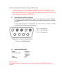
Safety Information in this Manual
Note, caution and warning symbols appear on the instrument and throughout this manual to
draw your attention to important operational and safety information.
A “NOTE” marks a short message to alert you to an important detail.
A “CAUTION” safety alert appears with information that is important for protecting your
equipment and performance.
A “WARNING” safety alert appears with information that is important for protecting you,
others and equipment from damage. Pay very close attention to all warnings that apply to
your application.
The
symbol (an exclamation point in a triangle) precedes a general CAUTION or
WARNING statement.
The
symbol (wavy vertical lines with an under score in a triangle) precedes an
elevated temperature hazard CAUTION or WARNING statement.
The
symbol (a lightning bolt in a triangle) precedes an electric shock hazard
CAUTION or WARNING statement.
Some or all of the above symbols may appear in this manual or on the equipment. This
manual should be consulted whenever one of these symbols is encountered on the
equipment.
ALWAYS REMOVE POWER BEFORE CONNECTING OR DISCONNECTING
SIGNAL CABLES OR WHEN SERVICING THE EQUIPMENT.
The 600 series CLD instruments meet or exceed the following
directives and standards.
Application of Council Directive(s):
Electrical Safety:
Low Voltage Directive 73/23/EEC
Electromagnetic Compatibility:
EMC Directive 89/336/EEC
Standard(s) to which Conformity is Declared:
Electrical Safety:
Standard for Electrical Equipment for Measurement, Control, and Laboratory Use
[EN 61010-1:2001 (2nd Edition)
Electromagnetic Compatibility:
EN 61326:1997 Electrical equipment for measurement, control and laboratory
use
- EMC requirements (Amendment A1: 1998 to EN 61326:1997;
Amendment A2:2001 to EN 61326:1997)
POSSIBLE EXPLOSION HAZARD
Do not apply power to the analyzer or attempt to energize the ozone supply or
converter until ALL leak checks have been performed and until the analyzer
environment has been determined to be non-hazardous.
This analyzer is designed for use in a NON-HAZARDOUS environment.
This analyzer is designed for use with a HAZARDOUS sample.
Tampering or use of substitute components may cause a safety hazard. Use only
factory authorized replacement parts.
Do not operate without the cover secured. Servicing
requires access to live electrical components which
can cause death or serious injury. Refer servicing to
qualified service personnel. For safety and proper
performance, this instrument must be connected to a
properly grounded three-wire receptacle.
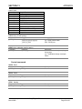
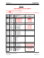
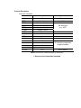
TABLE OF CONTENTS
Section Title
1.
INTRODUCTION -------------------------------------------------------------------------------- 1
1.1.
1.2.
1.3.
1.4.
1.5.
2.
Display --------------------------------------------------------------------------------------------9
Menu Tree-------------------------------------------------------------------------------------- 10
Keyboard --------------------------------------------------------------------------------------- 11
Operation with Cursor Keys --------------------------------------------------------------- 11
Operation with Function Keys ------------------------------------------------------------- 11
Read and Change Parameters ----------------------------------------------------------- 11
OPERATING STRUCTURE -----------------------------------------------------------------12
5.1.
6.
General--------------------------------------------------------------------------------------------5
Site and Mounting ------------------------------------------------------------------------------5
Electrical --------------------------------------------------------------------------------------- 5-6
OutputConnections ----------------------------------------------------------------------------6
Required Gases---------------------------------------------------------------------------------7
Gas Handling Equipment ---------------------------------------------------------------------7
Gas Connections -------------------------------------------------------------------------------5
Sampling Requirements ----------------------------------------------------------------------7
Filtration ----------------------------------------------------------------------------------------7
Condensation ---------------------------------------------------------------------------------7
Presence of Corrosive Gases-------------------------------------------------------------7
Gas Temperature ----------------------------------------------------------------------------7
Flow Rate ----------------------------------------------------------------------------------- 7-8
Sample Gas Outlet --------------------------------------------------------------------------8
BASIC OPERATION --------------------------------------------------------------------------- 9
4.1.
4.2.
4.3.
4.4.
4.5.
4.6.
5.
Descriptions--------------------------------------------------------------------------------------3
Features ------------------------------------------------------------------------------------------3
Specifications------------------------------------------------------------------------------------4
INSTALLATION --------------------------------------------------------------------------------- 5
3.1.
3.2.
3.3.
3.4.
3.5.
3.6.
3.7.
3.8.
3.8.1.
3.8.2.
3.8.3.
3.8.4.
3.8.5.
3.8.6.
4.
Overview------------------------------------------------------------------------------------------1
Unpacking Instructions------------------------------------------------------------------------1
Reporting Damage -----------------------------------------------------------------------------1
Contact Information ----------------------------------------------------------------------------1
Warranty Certificate----------------------------------------------------------------------------2
FEATURES AND SPECIFICATIONS ------------------------------------------------------ 3
3.1.
2.2.
2.3.
3.
Page
Main Menu ---------------------------------------------------------------------------------12-13
MENU STRUCTURE --------------------------------------------------------------------------13
6.1.
6.2.
6.3.
6.4.
7.
User Functions (Level 1) ------------------------------------------------------------------- 13
Advanced User Functions (Level 2) ----------------------------------------------------- 13
Maintenance User Functions (Level 3) ------------------------------------------------- 13
System User Functions (Level 4)--------------------------------------------------------- 13
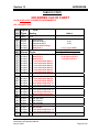
MAIN MENU -------------------------------------------------------------------------------------15
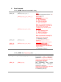
7.1.
F1 Measurements ---------------------------------------------------------------------------- 15
7.1.1.
F1 NO or NOx Measurement ----------------------------------------------------------- 16
7.1.2.
F2 NO + NO2 Measurement --------------------------------------------------------15-16
7.1.3.
F3 Diagnostics ------------------------------------------------------------------------------ 16
7.1.4.
Arrow Keys to Cycle Ranges and Auto Range ------------------------------------- 17
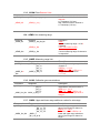
7.2.
F2 Purge Analyzer --------------------------------------------------------------------------- 18
7.3.
F3 Diagnostics -------------------------------------------------------------------------------- 18
7.4.
F4 Calibrations -------------------------------------------------------------------------------- 19
7.4.1.
F1 Automatic Calibration -------------------------------------------------------------19-20
7.4.2.
F2 Manual Calibration ----------------------------------------------------------------20-21
7.4.3.
F3 Display Deviations-----------------------------------------------------------------21-22
7.4.4.
F4 Check Calibration Values------------------------------------------------------------ 22
7.4.5.
F5 Reset Calibration Values ------------------------------------------------------------ 22
7.4.6.
F6 Range Select --------------------------------------------------------------------------- 22
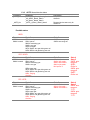
7.5.
F5 Setup ---------------------------------------------------------------------------------------- 23
7.5.1.
F1 Span Gas Concentrations ----------------------------------------------------------- 24
7.5.2.
F2 Calibration Settings ------------------------------------------------------------------- 24
7.5.2.1.
F1 Times --------------------------------------------------------------------------- 24
7.5.2.2.
F2 Measuring Deviations------------------------------------------------------- 25
7.5.2.3.
F3 Deviations---------------------------------------------------------------------- 25
7.5.2.4.
F4 Calibration via Valves------------------------------------------------------- 25
7.5.2.5.
F5 Calibration via Probe-------------------------------------------------------- 25
7.5.3.
F3 Range Limits ---------------------------------------------------------------------------- 25
7.5.3.1.
F1 Change Upper Range Limits---------------------------------------------- 25
7.5.3.2.
F2 Change Auto Range Limits------------------------------------------------ 26
7.5.4.
F4 Change Alarms------------------------------------------------------------------------- 26
7.5.5.
F5 Password -------------------------------------------------------------------------------- 27
7.5.5.1.
F1 Enter Password -------------------------------------------------------------- 27
7.5.5.2.
F2 Change Password ----------------------------------------------------------- 27
7.5.5.3.
F3 Reset Passwords ------------------------------------------------------------ 28
7.5.6.
F6 Linearization ---------------------------------------------------------------------------- 28
7.5.7.
F7 System Settings------------------------------------------------------------------------ 29
7.5.7.1.
F1 Clock Setup ---------------------------------------------------------------29-30
7.5.7.2.
F2 TCP/IP Address -------------------------------------------------------------- 31
7.5.7.3.
F3 Output Signal Assignments ----------------------------------------------- 31
7.5.5.4.
F4 Output Ranges --------------------------------------------------------------- 31
7.5.7.5.
F5 Protocol On/Off --------------------------------------------------------------- 32
7.5.7.6.
F6 Set Langauge ----------------------------------------------------------------- 32
7.5.7.7.
F7 Automatic Setup-------------------------------------------------------------- 32
7.5.8.
F8 Measure Settings ---------------------------------------------------------------------- 33
7.5.8.1.
F1 Set Purge Time Before Measure----------------------------------------- 33
7.5.8.2.
F2 Set Converter Efficieny ----------------------------------------------------- 33
7.5.8.3.
F3 Set Time Constant----------------------------------------------------------- 34
7.5.8.4.
F4 Set Purge Time Before Calibration -------------------------------------- 34
7.5.10. F10 Display Software Version ------------------------------------------------------34-35
7.6.
F7 Remote/Manual Operation------------------------------------------------------------- 35
7.7.
F8 Standby ------------------------------------------------------------------------------------- 35
8.
ANALYZER COMPONENTS ----------------------------------------------------------------36
8.1.
8.1.1.
8.1.2.
8.1.3.
8.1.4.
8.2.
8.3.
8.4.
8.5.
8.6.
9.
Rear Panel Connections-------------------------------------------------------------------- 36
Main Analog Connections---------------------------------------------------------------- 37
Auxiliary Analog Connections----------------------------------------------------------- 37
Digital (RS-232) Connections ----------------------------------------------------------- 38
Digital (TCP/IP) Connections ----------------------------------------------------------- 38
Internal Components ------------------------------------------------------------------------ 39
Main Electronics Board (Potentiometers) ---------------------------------------------- 40
Main Electronics Board (Connections)-------------------------------------------------- 41
Reaction Chamber --------------------------------------------------------------------------- 42
Relay Board (Connections) ---------------------------------------------------------------- 43
OPERATION-------------------------------------------------------------------------------------44
9.1.
9.2.
9.3.
Preparation------------------------------------------------------------------------------------- 44
Operation -----------------------------------------------------------------------------------44-45
Shut Down Procedure ----------------------------------------------------------------------- 45
10. FUNCTIONAL DESCRIPTION--------------------------------------------------------------46
10.1.
10.2.
10.3.
10.4.
10.5.
10.6.
Operating Principle--------------------------------------------------------------------------- 46
Reaction Chamber Assembly ------------------------------------------------------------- 46
Flow System ----------------------------------------------------------------------------------- 46
Electronics-------------------------------------------------------------------------------------- 46
Main Electronics Board --------------------------------------------------------------------- 47
Relay Board------------------------------------------------------------------------------------ 47
11. REACTION CHAMBER-----------------------------------------------------------------------48
11.1.
11.2.
Reaction Chamber Disassembly --------------------------------------------------------- 48
Reaction Chamber Assembly ------------------------------------------------------------- 48
12. TROUBLESHOOTING ------------------------------------------------------------------------49
12.1.
12.2.
12.3.
Ozone Air/O2 Supply ------------------------------------------------------------------------ 49
Sample Supply -------------------------------------------------------------------------------- 49
NO/NOx Converter --------------------------------------------------------------------------- 49
13. APPENDIX 1-------------------------------------------------------------------------------------50
13.1.
AK Protocol --------------------------------------------------------------------------------51-62
13.2.
13.3.
13.4.
13.5
I/O Lists ----------------------------------------------------------------------------------------- 63
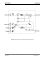
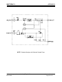
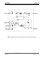
Flow Diagrams ----------------------------------------------------------------------------64-67
Electrical Block Diagram-------------------------------------------------------------------- 68
Serial Number UO6081--------------------------------------------------------------------70
Section 1
INTRODUCTION
1. Introduction
1.1. Overview
Congratulations and thank you! You have just purchased one of the most reliable gas
analyzers in the world. Before using the analyzer, please familiarize yourself with its
operation by reading this manual. If you have any questions, please do not hesitate to
call California Analytical Instruments for assistance. We want you to be a member of our
thousands of satisfied customers.
1.2. Unpacking Instructions
Open the shipping container and carefully remove the analyzer from the packing
materials. Inspect the instrument for any sign of damage. Remove the Top Cover
retaining screws. Visually check for loose parts or connectors that are not properly
seated. Verify all circuit boards and circuit board connections are secure. If all internal
components look normal, re-install the cover.
1.3. Reporting Damage
Should there be any apparent damage to either the inside or outside of the instrument
due to shipping or handling, immediately notify the shipper. The shipping container or
packing materials should be retained for inspection by the shipper.
1.4. Contact Information
California Analytical Instruments, Inc.
1312 West Grove Avenue
Orange, CA 92865
713 974-5560
Fax 713 921-2531
Website: www.gasanalyzers.com
California Analytical Model 600 CLD C_ETL_US/CE
Rev12
Operators Manual
Page 1 of 81
Section 1
INTRODUCTION
1.5. Warranty Certificate
Subject to the exceptions and upon the conditions stated below, California Analytical
Instruments (CAI) warrants that the products sold under this sales order shall be free
from defects in workmanship and materials for one year after delivery of the product to
the original Buyer by CAI and if any such product should prove to be defective within
such one year period, CAI agrees, at its option, either (i) to correct by repair or, at CAI’s
election, by replacement with equivalent product any such defective product, provided
that investigation and factory inspection discloses that such defect developed under
normal and proper uses, or (ii) to refund the purchase price. The exceptions and
conditions mentioned above are as follows:
a) components or accessories manufactured by CAI which by their nature are not intended to
and will not function for one year are warranted only to give reasonable service for a
reasonable time; which constitutes reasonable time and reasonable services shall be
determined solely by CAl. A complete list of such components and accessories is maintained
at the factory;
b) CAI makes no warranty with respect to components or accessories not manufactured by it; in
the event of defect in any such component or accessory CAI will give reasonable assistance
to Buyer in obtaining from the respective manufacturer whatever adjustment is authorized by
the manufacturer’s warranty;
c) any product claimed to be defective must be returned to the factory transportation charges
prepaid and CAI will return the repaired or replaced product freight collect;
d) if the product claimed to be defective requires on-site repair, such warranty labor will be
provided at no charge; however, transportation and living expenses will be charged to Buyer;
e) if the product is a consumable or the like, it is warranted only to conform to the quantity and
content and for the period (but not in excess of one year) stated on the label at the time of
delivery or 90 days;
f)
CAI may from time to time provide a special printed warranty with respect to a certain product,
and where applicable, such warranty shall be deemed incorporated herein by reference;
g) CAI shall be released from all obligations under all warranties, either expressed or implied, if
any product covered hereby is repaired or modified by persons other than its own authorized
service personnel unless such repair by others is made with the written consent of CAl.
IT IS EXPRESSLY AGREED THAT THE ABOVE WARRANTY SHALL BE IN LIEU OF ALL
WARRANTIES OF FITNESS AND OF THE WARRANTY OF MERCHANTABILITY AND THAT
CAI SHALL HAVE NO LIABILITY FOR SPECIAL OR CONSEQUENTIAL DAMAGES OF ANY
KIND OR FROM ANY CAUSE WHATSOEVER ARISING OUT OF THE MANUFACTURE USE,
SALE, HANDLING, REPAIR, MAINTENANCE OR REPLACEMENT OF ANY OF THE
PRODUCTS SOLD UNDER THIS SALES ORDER. SOME STATES DO NOT ALLOW THE
EXCLUSION OR LIMITATION OF INCIDENTAL OR CONSEQUENTIAL DAMAGES, SO THAT
THE ABOVE LIMITATIONS OR EXCLUSIONS MAY NOT APPLY. THIS WARRANTY GIVES
YOU SPECIFIC LEGAL RIGHTS, AND YOU MAY ALSO HAVE OTHER RIGHTS, WHICH VARY
FROM STATE TO STATE.
Representations and warranties made by any person, including dealers and representatives of
CAI, which are inconsistent, or in conflict with the terms of this warranty, shall not be binding upon
CAI unless reduced to writing and approved by an expressly authorized officer of CAl.
California Analytical Model 600 CLD C_ETL_US/CE
Rev12
Operators Manual
Page 2 of 81
Section 2
FEATURES AND SPECIFICATIONS
2. Features
2.1. Description
The CAI Model 600 CLD Analyzer is a highly sensitive chemiluminescent (CLD) gas
analyzer for measuring oxides of nitrogen gas concentrations in industrial and vehicle
emission applications.
2.2. Features-General
The Model 600 CLD analyzer has a 3 by 5 inch liquid crystal display and a 20 key
data/operation input keyboard. The 16 bit microprocessor control board consists of the
MSR-Card with 16 digital inputs, 16 digital outputs, 16 analog inputs and 4 analog
outputs. The analyzer can be manually operated from the keypad or remotely via TCP/IP
or RS-232C communications. After turning on the analyzer, it needs at least 30 seconds
for initialization. During this time, the screen is illuminated. The analyzer is available with
an optional internal heated sample pump and internal zero and span solenoids.
+
IMPORTANT TIP: When the analyzer is powered up, it defaults to access
level 1 (User). To operate ALL parameters, check the access level. See
Section 5.5.5.
The contents of this operators manual include:
•
Specifications
•
Installation Requirements, Mechanical & Electrical
•
Operation & Calibration Instructions
•
Reaction Chamber Description with Procedures for Disassembly of its
Component Parts
•
Function Explanation of the Electronic Circuitry
•
Electrical Block Diagram
NOTE: A detailed service and factory setup instruction manual for
purchase will be available in April 2003 and will include full
schematics.
California Analytical Model 600 CLD C_ETL_US/CE
Rev12
Operators Manual
Page 3 of 81
Section 3
BASIC OPERATION
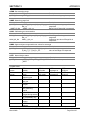
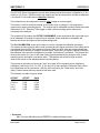
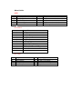
Model 600 CLD Specifications
DETECTOR
NO/NOx RANGES
RESPONSE TIME
RESOLUTION
REPEATABILITY
LINEARITY
NOISE
ZERO & SPAN DRIFT
ZERO & SPAN ADJUSTMENT
NH3, HCN & SO2 EFFECT
CO2 EFFECT
FLOW CONTROL
SAMPLE FLOW RATE
CONVERTER
OZONATOR
AIR OR O2 REQUIREMENTS
NO/NOXControl
OUTPUTS AVAILABLE
DISCRETE ALARMS
(Local & Remote Adjustable)
DIGITAL DIAGNOSTICS
KEYPAD DISPLAYS
SPECIAL FEATURES
DISPLAY
SAMPLE TEMPERATURE
AMBIENT TEMPERATURE
AMBIENT HUMIDITY
WARM-UP TIME
FITTINGS
POWER REQUIREMENTS
DIMENSIONS
Chemiluminescence (CLD) Photodiode (thermally stabilized with Peltier Cooler)
0-1 to 3,000 ppm NO or NOX (Four user programmable ranges)
(Higher Ranges Available upon Request)
T90 < 2 Seconds to 60 Seconds Adjustable
10 ppb NO/NOX (Displays 5 significant digits)
Better than 0.5% of Full Scale
Better than 0.5% of Full Scale
Less than 1% of Full Scale
Less than 1% of Full Scale per 24 Hours
Via front panel, TCP/IP or RS-232
Not detectable with 100 ppm
Less than 0.5% with 10% CO2
Electronic Proportional Pressure Controller
.5 to 3.0 LPM (See footnote below)
Vitreous Carbon Material @ 205°C > 98% efficiency
Ultraviolet Lamp
Less than 0.01 ppm NOXat 350 cc/Min. @ 25 psig (Dew Point < -35ºC)
Manual/Remote/Auto Cycle (Remote NOX mode by dry contact closure)
TCP/IP, RS232, Four Scalable Analog 0-10 V / 4-20 mA Maximum
General Fault/ TTL Logic (Ground True)
Calibration Failure/ TTL Logic (Ground True)
High Concentration (2 each)/ TTL Logic (Ground True)
Control Voltages
Pressures
Temperatures
Flow Parameters
Factory Settings
Scalable Analog Output Voltages
TCP/IP Address
Full Scale Range Select
Passwords (4)
Auto Cal Times
Calculated NO2 derived from NOX converter efficiency
Auto Ranging
Auto Calibration (adjustable through internal clock)
Less than 3 cc Gold Plated Reaction Chamber
3” x 5” Back lit LCD
Up to 50°C Noncondensing
5 to 40°C
Less than 90% RH Noncondensing
1 Hour (Typical)
1/4 Inch Tube
115V 60Hz (Option: 230V 50 Hz) , ± 10%, 500 W
5¼ H × 19 W × 23 D (Inches)
Note: .5 to 1.5 l/min flow rate options available upon request only
SPECIFICATIONS ARE SUBJECT TO CHANGE WITHOUT NOTICE
California Analytical Model 600 CLD C_ETL_US/CE
Rev12
Operators Manual
Page 4 of 81
Section 3
BASIC OPERATION
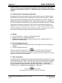
3. Installation
3.1. General
The instrument is designed for industrial applications. These installation instructions are
for a typical site. Any questions regarding specific installation situations should be
directed to Technical Service of California Analytical Instruments, Inc.
3.2. Site and Mounting
NOTE: The following precautions must be carefully observed:
1. Select a site free from direct sunlight, radiation from a high temperature surface,
or abrupt temperature variations.
2. This analyzer is not suitable for installation outdoors.
3. Select a site where the air is clean. Avoid exposing the instrument to corrosive or
combustible gases.
4. The instrument must not be subject to severe vibration. If severe vibration is
present, use isolation mounts.
5. The instrument is designed for rack-mounting. Optional rack mount slides are
available.
6. Do not install near equipment emitting electromagnetic interference (EMI).
NOTE: A rear supporting brace or equivalent is required if the optional rack mount
slides were not purchased.
The power on/off switch is accessible from the rear of the instrument only. DO
NOT mount such that the power on/off switch is inaccessible.
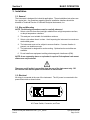
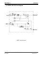
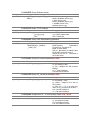
3.3. Electrical
All wiring is connected at the rear of the instrument. The AC power is connected to the
power/fuse/switch as shown below:
I
0
AC Power Switch, Connector, and Fuse.
California Analytical Model 600 CLD C_ETL_US/CE
Rev12
Operators Manual
Page 5 of 81
Section 3
BASIC OPERATION
NOTE: A defective ground may affect the operation of the instrument. The output
voltages are connected per Table 8.1.1. Shielded wiring is recommended for output
signals.
3.4. Analog Output Connections (Appendix)
See Appendix for connector pinouts located on the analyzer rear panel. Remote range
identification and range selection are obtained via the rear panel connections. When a
range is selected, the corresponding control line is pulled low to zero VDC. Ranges not
selected will remain at approximately 5 VDC. When remote range control is selected on
the front panel switch, a contact closure is provided at the rear panel connector. Remote
range selection is made by connection of the control line for the desired range to the
analyzers zero VDC line provided in the connector. Five VDC is also provided. Remote
NOx On is selected by connection to the common line. This contact closure turns on the
NOx function by flowing the sample first through the NO/NOx converter.
3.5. Gases
1. Air or O2 (Ozone Air, < 1 ppm C) in pressurized cylinder.
2. Nitrogen or (zero air) in pressurized cylinder.
3. Standard span gas(es) near full scale concentration with a nitrogen balance, in a
pressurized, certified cylinder.
3.6. Gas Handling Equipment
1. Pressure regulators for zero gas (Air or N2), ozone supply (air or O2) and span gas
cylinders.
2. Corrosive resistant gas tubing.
NOTE
High levels of Ammonia (greater than 10 PPM NH3) may reduce the NO2 to NO Converter's
conversion efficiency to a level that is unacceptable. It is therefore recommended that the
customer purchase a commercially available NH3 scrubber and install it in the path of the sample
gas prior to its introduction into the analyzer.
3.7. Gas Connections
The tubing from the sampling system to the gas analyzer should be made from corrosiveresistant material such as Teflon or stainless steel. Even when the gases being sampled
are corrosive themselves, rubber or soft vinyl tubing should not be used since readings
may be inaccurate due to gas absorption into the piping material. To obtain fast
response, the tube should be as short as possible. Optimum tube internal diameter is
0.16 inch (4 mm). Couplings to the instrument are ¼ Inch tube.
NOTE
Be sure tubing and joints are clean.
Dust entering the instrument may cause it to malfunction.
California Analytical Model 600 CLD C_ETL_US/CE
Rev12
Operators Manual
Page 6 of 81
Section 3
BASIC OPERATION
3.8. Sampling Requirements
3.8.1. Filtration
Dust must be eliminated completely. Use filters as necessary. The final filter must be
capable of removing particles larger than 4 microns.
3.8.2. Condensation
Dew point of the sample gases must be lower than the instrument temperature to
prevent accidental condensation within the instrument. Pypass the sample through a
dehumidifier to reduce the dew point to about 2 to 4°C or less. If the sample contains
an acid mist, use an acid mist filter, cooler or similar device to remove all traces of the
mist.
3.8.3. Presence of Corrosive Gases
Useful service life of the instrument will be shortened if high concentrations of
corrosive gases such as Cl2, SO2, F2, HCl, etc., are present in the sampled gas.
3.8.4. Gas Temperature
When measuring high temperature gases, take care that the maximum rating of the
instrument 104 ºF (50 ºC) is not exceeded.
3.8.5 Pressure and Flow Rates
The air or oxygen supply entering the instrument is controlled by an electronically
controlled proportional flow (EPC) controller. The regulator is factory adjusted for
optimum analyzer performance. The ozone supply (Air or O2) air cylinder pressure
should be set at approximately 25 PSIG. The sample entering the instrument is
controlled by a factory set precision electronically controlled proportional flow (EPC)
controller. The EPC is factory set for optimum analyzer performance as indicated by
the sample pressure. If the analyzer does not contain the optional internal sample
pump, the sample gas entering the instrument should be at a pressure between 10
and 25 PSIG with a flow capacity at a minimum of 3 liters/min. If the analyzer
contains the optional sample pump, do not apply a pressurized sample. The optional
pump is capable of drawing a sample through a ¼ inch heated sample line of
approximately 75 feet. The calibration/span gas cylinder pressures should be set at
25 PSIG for delivery into the optional zero and span inlets located on the rear panel.
NOTE: If the analyzer contains an optional internal sample pump, the introduction of
a pressurized sample gas in excess of 1.5 PSIG will damage the pump.
3.8.6. Sample Gas Bypass Outlet (Vent)
A sample gas bypass outlet connector is located on the rear panel (¼ Inch Tube).
Pressure at this outlet should be kept at atmospheric level. ANY backpressure will
cause an error in reading. The vent outlet is located on the rear panel and may
contain high levels of ozone which should be vented away from the instrument.
California Analytical Model 600 CLD C_ETL_US/CE
Rev12
Operators Manual
Page 7 of 81
Section 3
BASIC OPERATION
4. Basic Operation
The operation of the digital microprocessor conforms to the guidelines of the AK committee,
originally developed in the German automotive industry. Via the serial port of the MSR-Card,
the analyzer can be remote-controlled by a master computer. The serial communication fully
corresponds to the specifications of the AK protocol. TCP/IP communication is also
available.
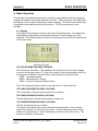
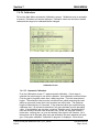
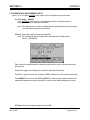
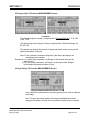
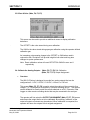
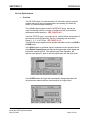
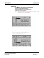
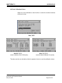
4.1. Display
The analyzer's LCD display includes 16 lines with 30 characters each. The display also
has background lighting that can be switched on and off via the Display key on the
keyboard. The following example shows the measurement screen which is formatted into
4 information areas.
Measurement Screen
THE TOP INFORMATION AREA CONTAINS:
The AK Protocol Information. This capability is for advanced uses and may be toggled
on and off in the setup screen, F5. Next to the symbol for the active operating mode, the
device status is indicated. The status field is also displayed on all other screens.
SARE Autorange enabled
SMGA Measuring gas is flowing
SMAN Device is in manual operation status
The level of Password Entry is shown on the right with 1 to 4 horizontal lines.
THE LARGE INFORMATION AREA CONTAINS:
The Concentration of the gas sample and mode of operation.
THE THIRD INFORMATION AREA CONTAINS:
The help information for the parameter selected, ranges, etc.
THE LOWER INFORMATION AREA CONTAINS:
The time & date and any error condition.
The symbol in the bottom right corner indicates the keyboard mode. In the example
shown, the keyboard is in the function key mode. For input fields, the mode is usually
switched to numerical input. Then, an N appears in the lower right of the screen. This
symbol is displayed on all screens.
California Analytical Model 600 CLD C_ETL_US/CE
Rev12
Operators Manual
Page 8 of 81
Section 3
BASIC OPERATION
4.2. Menu Tree
Main Menu (from “Main” Key) (p12)
F1 Measurement
F2 Purge Analyzer
F3 Diagnostics
F4 Calibration
F5 Setup
F6 Remote / Manual
F7 Standby
F1
F2
F3
F4
F5
F1 NO/NOx
F2 Dual Mode
F3 Diagnostics
Up/Down Range
Purge Analyzer
F1 Toggles Between NO & NOx (p15)
F2 Toggles on NO +NO2 (p15)
F3 Displays Diagnostics Screen (p16)
Arrow Keys Cycle Ranges 1-4 and Auto Range (p17)
Sets Analyzer in Purge Mode (p18)
Displays Diagnostics Screen
F1 Auto Cal
F2 Manual Cal
F3 Display Deviations
F4 Check Calibration
F5 Reset Cal Values
F6 Range Select
F3 (p15)
F1 Starts Auto Calibration on Range in Use (p19)
F2 (Zero Cal/Span Cal/Change Range) (p20)
F3 Displays Deviations (p21)
F4 Calibration Check (p22)
F5 Reset to Factory Default (p22)
F6 Range Change (p22)
F1 Span Gas Concentrations
F2 Calibrations Settings
F3 Range Limits
F4 Alarms
F5 Password
F6 Linearization
F7 System Settings
F8 Measure Settings
F10 Displays Version
Activates Remote or Manual
Control
F6
F1 Sets Calibration Gas Values (p24)
F2 Sets Auto Calibration Times (p24)
F3 Sets Upper Range Limits (p25)
F4 Set Range Concentration Limits (p26)
F5 Sets User Password (p27)
F6 Enters Curve Fit Polynomials (p28)
F7 Displays System Settings (p29)
F9 Displays Measure Settings (p33)
F10 Displays Converter Efficiency (p34)
Manual (Local) Control (p36)
F6
In Standby, Sample Pump is OFF
Toggles Pump ON/OFF (p36)
F7
California Analytical Model 600 CLD C_ETL_US/CE
Rev12
Operators Manual
Page 9 of 81
Section 3
BASIC OPERATION
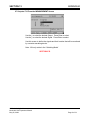
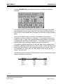
4.2. Keyboard
The keyboard looks as follows:
Combined control / numeral keys
F1
1
Display lighting
on / off
F6
6
F2
F3
F4
F7
F8
F9
2
7
3
Del
8
4
F5
5
F10
9
Main Back
Delete key
Switch-over of the keyboard
numeral / control keys
0
To the main menu
Cancel, back to
the last menu
End input,
open selected field for input
Arrow keys for selecting the functions and
editing fields and for scrolling possible input values
Keyboard
4.3. Operation with the Cursor Keys and the Enter Key
When operating the unit with the cursor keys, you select the various functions with the
up/down cursor keys and start them with the Enter key. This method is particularly
suitable for less proficient users since the system displays a short on-line help for nearly
every function selected. The actual cursor position is shown as a black horizontal bar.
TIP: If you are not yet familiar with the screens and their fields, just press any cursor key
after a screen appears. This moves the cursor from field to field and displays the
corresponding online help.
4.4. Operation with the Function Keys
When using the function keys (Fl though F10), functions are directly accessed by
pressing their corresponding function keys. This method is suitable for the advanced user
since it is faster than the operation with the cursor keys.
4.5. Read/Change Parameters
To read and/or change parameters, you must switch to the parameter input mode by
pressing the Enter key after calling the corresponding parameter screen. The input
cursor (horizontal bar under the first character) then appears in the active edit field (black
background). The cursor can be positioned with the right and left cursor keys, and the
value displayed (number or letter) can be changed with the up and down cursor keys or
entered directly. Every input has to be concluded by pressing the Enter key again, which
causes the cursor to disappear.
California Analytical Model 600 CLD C_ETL_US/CE
Rev12
Operators Manual
Page 10 of 81
Section 5
OPERATING STRUCTURE
5. Operating Structure
The analyzer’s operation can be divided into 4 operating levels. The current level is always
displayed as a stack of 1 to 4 horizontal bars in the top right corner of the screen. In the
access level menu, you can choose between the following operating levels:
F1
User
(operating level 1)
F2
Advanced user
(operating level 2)
F3
Maintenance
(operating level 3)
F4
System user
(operating level 4)
A password can be assigned to each operating level. Only the system user, who normally
has the highest operating priority, can assign the password. At the factory, the default
passwords for the CAI analyzers are set as follows:
User:
Advanced user:
Maintenance:
System:
111
222
333
444
The default setting can be changed only by the system user. This manual is written to
include all information for the advanced system user.
TIP: Because of the user settings, some of the parameters shown in this manual may not
appear on your analyzer. Check the access level.
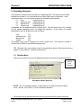
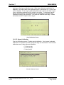
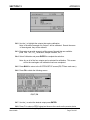
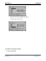
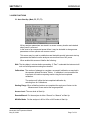
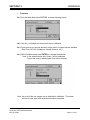
5.1. The Main Menu
Upon power up,the CAI logo is first displayed and then the main menu appears as below:
NOTE:
Access
Level
Indication
Main Menu onPower Up Screen
NOTE: F6 is not available because, on initial start up, the analyzer reverts to ONLY
Level 1 access. See Section 7.5.5 for Password information.
All functions can be selected with the cursor keys and activated by pressing the Enter
California Analytical Model 600 CLD C_ETL_US/CE
Rev12
Operators Manual
Page 11 of 81
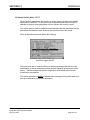
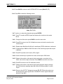
Section 5
OPERATING STRUCTURE
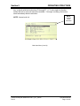
key, or directly with the function keys F1 through F7. A ">" to the right of a function
means that one or more sub-menus are available. If this sign is missing, the function
starts immediately after the activation.
NOTE:
Access
Level
Indication
NOTE: Access level is 4.
Main User Menu (Level 4)
California Analytical Model 600 CLD C_ETL_US/CE
Rev12
Operators Manual
Page 12 of 81
Section 6
MENU STRUCTURE
6. Menu Structure
There are 4 operating levels based on the level of your password. This section shows the
access rights of the single levels.
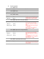
6.1. User Functions (Level 1)
Main Menu
F5 :Setup
F5 :Password
F1 : Measurements
F2 : Purge Analyzer
F3 : Diagnostics
F4 : Calibrations
F5 : Setup
F7 : Standby
F5 : Password
F10:Version
F1 :Enter password
6.2. Advanced User Functions (Level 2)
Main Menu
F5 : Setup
F1 : Measurements
F2 : Purge Analyzer
F3 : Diagnostics
F4 : Calibrations
F5 : Setup
F7 : Standby
F3 : Range Limits
F5 : Password
F10:Version
F5 :Password
F1 :Enter password
6.3. Maintenance Functions (Level 3)
Main Menu
F5 : Setup
F1 : Measurements
F2 : Purge Analyzer
F3 : Diagnostics
F4 : Calibrations
F5 : Setup
F7 : Standby
F1 : Span Gas Conc.
F3 : Range limits
F5 : Password
F7 : System Settings
F8 : Measure Settings
F10:Version
F5 :Password
F7:System Settings
F1 :Enter password
F2 :Reset password
F1 : Real Time Clock
F5 : Status Line on/off
F7 : Auto Startup
6.4. System User Functions (Level 4)
All functions described in this manual may be accessed from Level 4.
California Analytical Model 600 CLD C_ETL_US/CE
Rev12
Operators Manual
Page 13 of 81
Section 7
MAIN MENU
7. Main Menu Function Descriptions
7.1. F1 Measurements
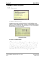
7.1.1. F1 NO or NOx Measurement
The measurements screen is activated by pressing F1 on the Main Menu screen.
The NO/NOx content is displayed in ppm. Pressing F1 switches between measuring
the sample gas for NOx or NO only. When the converter is off, only NO is measured.
When the converter is on, NOx is measured.
Measurements Screen
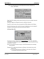
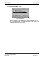
7.1.2. F2 NO + NOx Measurement
The F2 function activates the “hold and sample“ feature which allows the analyzer to
automatically switch between NO and NOx measurement. The time duration for the
sample read is set up in the Setup Menu. The analyzer will read and display the NO
(converter is bypassed) value. At the predetermined time, it will switch to the NOx
mode (through converter) and read and display the NOx value, while the last 15
second NO average is displayed. The top value will be “real time“ values and will
change between NO and NOx. The difference between the two average values is
shown as NO2. All three values are sent to the analog and digital outputs.
California Analytical Model 600 CLD C_ETL_US/CE
Rev12
Operators Manual
Page 14 of 81
Section 7
MAIN MENU
NO/NOx/NO2 Screen
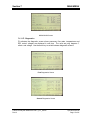
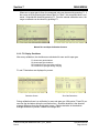
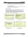
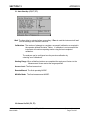
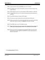
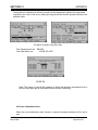
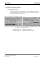
7.1.3. F3 Diagnostics
F3 activates the diagnostic screen where pressures, flow rates, temperatures and
EPC control voltages are displayed in real time. The units are psig, degrees C,
ml/min. and voltage. Use the arrow key to switch between diagnostic screens.
First Diagnostics Screen
Second Diagnostics Screen
California Analytical Model 600 CLD C_ETL_US/CE
Rev12
Operators Manual
Page 15 of 81
Section 7
MAIN MENU
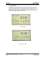
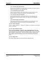
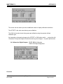
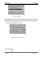
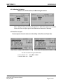
7.1.4. Range Select
With the arrow keys, the ranges 1 to 4 can be selected and locked in which will
disable the auto range capability. Continue pressing the arrow keys will recycle the
analyzer back to auto range. The range and/or auto range is displayed on the
measurement screen. If the limits are exceeded while not in the auto range mode, a
warning ”Over Range” appears on the screen.
Set to Auto-Range
Analyzer Set to Range 3
California Analytical Model 600 CLD C_ETL_US/CE
Rev12
Operators Manual
Page 16 of 81
Section 7
MAIN MENU
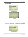
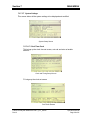
7.2. F2 Purge Analyzer
Main Menu (User Level 4)
Purge Screen
F2 from the Main Menu activates the Purge (analyzer) function if equipped.
7.3. F3 Diagnostics
F3 from the Main Menu activates the Diagnostics function. As described in Section 7.1.3,
F3 brings up the two diagnostics screens. The Diagnostics screens may be brought up
from EITHER the Main Menu or the Measurements screen.
Main User Menu (Level 4)
California Analytical Model 600 CLD C_ETL_US/CE
Rev12
Operators Manual
Page 17 of 81
Section 7
MAIN MENU
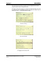
7.4. F4 Calibrations
F4 from the Main Menu activates the Calibrations screen. Calibrations may be automatic
or manual. Deviations can also be displayed. Calibration values can be reset to default
values and the range to be calibrated can be changed.
Main Menu (User Level 4)
Calibration Screen
7.4.1. F1 Automatic Calibration
From the Calibrations screen, F1 starts automatic calibration. If auto range is
selected, the actual range in use will be calibrated. Auto calibration works as follows:
First zero gas is purged a certain time, called purge-time. Then the measurement
begins. The measured value must be a minimum-time, called measuring-time and
within an upper and a lower limit to be saved as new offset value. The maximum
length of measuring time is 9 seconds. If the measured value was constant during
calibration time, it is checked to determine if this value deviates from the preceding
value. If the deviations are too large, a warning ”Deviation error!” appears and the
user can choose if the new value is saved or not. At last, the zero gas is flown a
further time, verifying time, so it can be checked if the signal is still constant. All of
these times can be changed. After zero gas calibration, the same happens with span
gas. During auto calibration ”Calibration in progress” is displayed. It also shows,
California Analytical Model 600 CLD C_ETL_US/CE
Rev12
Operators Manual
Page 18 of 81
Section 7
MAIN MENU
which gas is flowing and which time runs. When auto calibration has finished it is
displayed. If the span value of the selected range is 0 (see section 5.6.1), then it will
not be calibrated. If one range is calibrated and the span value for the lower ranges
is zero, calibration parameters will be copied to this range. To calibrate all ranges
with the same span gas, you must enter the gas concentration in the Span Gas
Calibration screen for ALL RANGES. You must also calibrate each range. Offsets
and scalors are NOT copied to other ranges.
Auto Calibration Screen
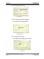
7.4.2. F2 Manual Calibration
From the Calibration screen, F2 starts manual calibration. If auto range is selected,
calibration is not possible, and the appropriate range can be selected. In the manual
calibrations menu, three options are possible:
F1 Flow zero gas
F2 Flow span gas
F3 Range select
Manual Calibration Screen
California Analytical Model 600 CLD C_ETL_US/CE
Rev12
Operators Manual
Page 19 of 81
Section 7
MAIN MENU
When zero or span gas is flown, the measured value can be saved by pressing F1. If
the screen is left by pressing the buttons ”Main” or ”Back”, the measured value is not
saved. Solenoids are closed by pressing F2. From the manual calibration menu, the
range to calibrate can be chosen by pressing F3.
Manual Zero and Span Calibration Screens
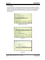
5.4.3. F3 Display Deviations
After every calibration, the deviations are calculated for zero and for span gas.
F1 shows zero gas deviations
F2 shows span gas deviations
F3 Deviations of zero gas during verifying
F4 Deviations of span gas during verifying
F1 and F2 deviations are displayed in percent.
Deviation Screen
Zero Gas Deviations
During calibration there is a verification for zero and span gas. With option F3 and F4 you
can view the deviations during the verification time. Absolute deviation is the absolute
average difference from the saved value in ppm. Relative deviation is the absolute
average difference in percent, related to the range limit.
California Analytical Model 600 CLD C_ETL_US/CE
Rev12
Operators Manual
Page 20 of 81
Section 7
MAIN MENU
7.4.3.1 Absolute Zero Gas Deviation
Absolute zero gas deviation is zero gas content calculated by the factory polynom
related to the range limit of the calibrated range.
7.4.3.2. Relative Zero Gas Deviation
Relative zero gas deviation is the actual deviation minus the deviation of the
previous calibration related to the range limit of the calibrated range.
7.4.3.3. Absolute Span Gas Deviation
Absolute span gas deviation is span gas bottle value minus span gas value
calculated by the factory-polynom related to the range limit of the calibrated
range.
7.4.3.4. Relative Span Gas Deviation
Relative span gas deviation is the actual deviation minus the deviation of the
previous calibration related to the range limit of the calibrated range.
7.4.4. F4 Check Calibration
There is a default calibration. Pressing F4, activates an automatic zero and span
check for verification.
7.4.4. F5 Reset Calibration Values
There is a default calibration. Pressing F5, a new screen appears and asks if the
user is sure to reset calibration values to the default calibration values. F1 confirms
and the calibration values are reset to default calibration values. F2 leaves this menu
without resetting to default values. This function will overwrite all calibrations with
factory values. Also the linearization polynom will be overwritten with the factory
values.
7.4.5. F6 Range Select
This allows a range change to be activated from the calibration menu.
California Analytical Model 600 CLD C_ETL_US/CE
Rev12
Operators Manual
Page 21 of 81
Section 7
MAIN MENU
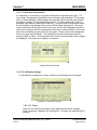
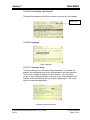
7.5. F5 Setup
From the Main Menu, F5 brings up the setup menu. Span gas concentrations, calibration
settings, range limits, alarms, password, linearization, system and measure settings can be
changed. The Setup menu begins as shown below. A description of each parameter is
shown in the information box. NOTE: Use the down arrow key to obtain the additional
setup parameters.
Main Menu (User Level 4)
Setup Menu 1
Setup Menu 2
California Analytical Model 600 CLD C_ETL_US/CE
Rev12
Operators Manual
Page 22 of 81
Section 7
MAIN MENU
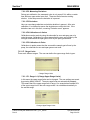
7.5.1. F1 Span Gas Concentration
For calibration, it is necessary to input the concentration of the span gas in ppm. For
every range, the span gas concentration can be changed. After pressing F1 in the setup
menu, a screen appears in which changes can be made. Select with the cursor buttons
the range to change. The selected field turns black. To change parameters, switch to
parameter input mode by pressing the Enter key. The input cursor (horizontal bar under
the first character) then appears in the active edit field (black background). The cursor
can be positioned with the right and left cursor keys, and the value displayed (number or
letter) can be changed with the up and down cursor keys or entered directly. Every input
has to be concluded by pressing the Enter key again. Then the input cursor disappears
and a new range can be selected. The changes are saved by leaving the screen by
pressing ”Main” or ”Back”. At the right side of the screen, the range limits of the 4 ranges
are displayed. They cannot be changed in this screen.
Change Span Gas Settings
7.5.2. F2 Calibration Settings
In the calibration settings menu, times, deviations and methods can be changed.
Change Auto Calibration Settings
7.5.2.1 F1 Times
There are four times (in seconds) for auto calibration that can be changed.
Purge, measuring, calibration and verifying time. Changes are made and saved
as above.
California Analytical Model 600 CLD C_ETL_US/CE
Rev12
Operators Manual
Page 23 of 81
Section 7
MAIN MENU
7.5.2.2 F2 Measuring Deviations
During auto calibration, the measured value is only saved if it is within a certain
time within an upper and a lower limit. These two limits format a working
window. In the setup menu the deviation is in percent.
7.5.2.3 F3 Deviations
Here you can change absolute and relative deviation in percent. After auto
calibration, it is checked to assure the deviations are within this limit. If the
deviations are not in this limit, a warning ”Deviation error!” appears.
7.5.2.4 F4 Calibrations via Valves
Calibrations can be made by using the solenoids for zero and span gas or by
using the pump. Calibration via valves means that the zero gas is flown by the
zero gas solenoid and the span gas is flown by the span gas solenoid.
7.5.2.5 F5 Calibration via Probe
Calibration via probe means that the zero and the sample gas is flown by the
pump, the solenoids for zero and span gas are not used.
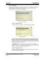
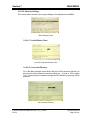
7.5.3. F3 Range Limits
There are 4 different ranges. The user can define the upper range limits in ppm.
Change Range Limits
7.5.3.1 F1 Range 1-4 (Change Upper Range Limits)
In this menu the upper range limits can be changed. The new settings are saved
by pressing MAIN or BACK. The auto range limits are automatically adapted.
This means that if the upper range limit of range 1 for example has reached 90%
of the upper range limit in the auto range mode, it is switched automatically to
the second range.
Change Upper Range Limits
California Analytical Model 600 CLD C_ETL_US/CE
Rev12
Operators Manual
Page 24 of 81
Section 7
MAIN MENU
7.5.3.2 F2 Change Auto Range Limits
Although the auto range limits are adapted automatically, it is possible to define
them manually. Up means the value when the next higher range is selected in
auto range mode, down the value when the next lower range is selected.
Change Auto Range Limits
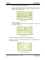
7.5.4. F4 Alarms
Error reports are always displayed In the lowest line of the screen. There are two
pressures, three temperatures, one concentration and two voltages with alarm limits
that can be defined. The user can define the range limits and, If exceeded, will display
an error-message.
Set Temperature Alarms
Set Concentration, Pressure and Voltage Alarms
California Analytical Model 600 CLD C_ETL_US/CE
Rev12
Operators Manual
Page 25 of 81
Section 7
MAIN MENU
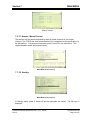
7.5.5. F5 Password
After turning on the analyzer, you are in access level 1. To change the access level
or to change the passwords, press F5 (Setup) in the main menu and Press F5
(Password) again. The following screen appears:
Enter / Change Password
7.5.5.1 F1 Enter Password
To change access level, press F1. The following screen appears:
Access Level Screen
F1 to F4 selects an access level. Move the cursor to the access level to be
modified. You must enter the correct password for the access level desired.
The passwords for the various operation levels consist of three numbers that
must to be entered on the numeric keypad. If the code word is incorrect, you
are asked to re-enter the codeword.
+ IMPORTANT TIP: When a new analyzer is powered up, it defaults to
access level 1 (User). To operate ALL parameters and gain complete access,
select F4. Press the Enter key twice and enter 444.
7.5.5.2 F2 Change Password
The passwords can only be changed, if you are in access level 4. After F2,
enter your new 3 digit passwords.
California Analytical Model 600 CLD C_ETL_US/CE
Rev12
Operators Manual
Page 26 of 81
Section 7
MAIN MENU
+ IMPORTANT TIP: You MUST remember and record this new password. If
this is lost, you will need to consult the factory for the default password !!
7.5.5.3 F3 Reset Passwords
The passwords can only be changed, if you are in access level 4. Reset
passwords will revert back to the factory defaults.
7.5.6. F6 Linearization
Pressing F6 on the Setup screen brings up the Linearization screen. The analyzer
can be linearized by a polynom with 5 coefficients. By pressing F1, these 5
coefficients can be changed for each range. By pressing F2, the raw value can be
displayed. This is the value before linearization and offset span correction. There
are two values on the screen: The value at the top is the linearized, offset-spancorrected value, and the other value is the raw-value.
Linearization Screen Linearization
Change Linearization Coefficients
of Selected Range
California Analytical Model 600 CLD C_ETL_US/CE
Rev12
Coefficients Range Select
Example of Linearized and
Raw Data with F2
Operators Manual
Page 27 of 81
Section 7
MAIN MENU
7.5.7. F7 System Settings
This screen allows all the system settings to be displayed and modified.
System Setup Screen
7.5.7.1 F1 Real Time Clock
This brings up the clock time set screen, auto cal and auto cal enable
screens.
Clock and Timing Setup Screen
F1 brings up the clock set screen
Set Clock Screen
California Analytical Model 600 CLD C_ETL_US/CE
Rev12
Operators Manual
Page 28 of 81
Section 7
MAIN MENU
The current time may be set by using the cursor to highlight the entry and
using the numeric keys to change the values.
F2 brings up the auto cal time set. As above, the date and times can be set
by using the cursor to highlight the entry and using the numeric keys to
change the values. F3 Sets autocalibration ranges.
Set Auto Cal Timing
Set Auto Cal Ranges
F4 Toggles Auto Cal ON of OFF.
California Analytical Model 600 CLD C_ETL_US/CE
Rev12
Operators Manual
Page 29 of 81
Section 7
MAIN MENU
7.5.7.2 F2 Displays TCP/IP Address
TCP/IP Address
7.5.7.3 F3 Displays Output Signal Assignments
(Used to Adjust Analog Output Channels)
Output Assignments
7.5.7.4 F4 Displays Output Ranges
(Used to Adjust Scale of Analog Output Channels)
Output Ranges
California Analytical Model 600 CLD C_ETL_US/CE
Rev12
Operators Manual
Page 30 of 81
Section 7
MAIN MENU
7.5.7.5 F5 Turns Status Line On or Off
The status line displays the AK Protocol action on the top line of the display.
Status Line
7.5.7.6 F6 Language
Select Language
7.5.7.7 F7 Automatic Setup
This screen brings up the automatic startup parameters. If activated, the
analyzer will automatically start up the autocalibration cycle upon power on.
The function is toggled on and off with the Enter key. The cycle timing,
number of cals, range and NO/Nox mode may be set. After calibration, the
analyzer enters the sample mode and outputs a digital signal. This is very
useful in unattended applications.
Automatic Startup Parameters
California Analytical Model 600 CLD C_ETL_US/CE
Rev12
Operators Manual
Page 31 of 81
Section 7
MAIN MENU
7.5.8. F8 Measure Settings
This screen allows several of the system settings to be displayed and modified.
Menu Settings Screen
7.5.8.1 F1 Set NO2 Mode Times
Set NO2 Purge and Measure Time
7.5.8.2 F2 Converter Efficiency
F2 on the Menu Settings screen allows the NO to NO2 converter efficiency to
be set to the actual measured converter efficiency. A value of 100% equals
1.00. F2 will prompt the operator through the NOx efficiency test using a NOx
generator.
Set Converter Efficiency
California Analytical Model 600 CLD C_ETL_US/CE
Rev12
Operators Manual
Page 32 of 81
Section 7
MAIN MENU
7.5.8.3 F3 Low Pass Filter Time Constant
F3 on the Menu Settings screen allows the software time constant to be set
between 1 and 60 seconds. This is very useful in eliminating noise when
measuring low level concentrations.
Set Time Constant
7.5.8.4 F4 Purge Time
F4 on the Menu Settings screen the sets the purge time before continuing with
a zero or span calibration.
Set Purge Time
7.5.10. F10 Displays the Current Analyzer and Software Versions
This displays the analyzer’s information, including the factory recommended air and
sample pressure settings.
Analyzer Information Version
California Analytical Model 600 CLD C_ETL_US/CE
Rev12
Operators Manual
Page 33 of 81
Section 7
MAIN MENU
Software Version
7.6. F7 Remote / Manual Control
The analyzer can be remote-controlled by either a master computer or via contact
closures. The TCP/IP and serial communication fully corresponds to the specifications of
the AK protocol. To change remote/manual control, press F6 in the main menu. This
toggles between remote and manual control.
Main Menu (User Level 4)
7.7. F8 Standby
Main Menu (User Level 4)
In Standby mode, pump is turned off and the solenoids are closed. The CAI logo is
displayed.
California Analytical Model 600 CLD C_ETL_US/CE
Rev12
Operators Manual
Page 34 of 81
Section 8
ANALYZER COMPONENTS
8. Analyzer Components
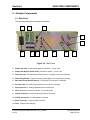
8.1. Rear Panel
The following details the rear panel connections:
5
9
10
2
1
4
11
7
3
6
12
8
Figure 32: Rear Panel
1. Sample Gas Inlet: Feeds sample gas to the analyzer. ¼ Inch Tube.
2. Sample Gas Bypass Outlet (Vent): Exhaust for sample. ¼ Inch Tube.
3. Ozone Air Inlet: For feeding hydrocarbon free air or oxygen to the ozone generator.
4. Power Entry Module: Power connection, power switch, fuse compartment (2 Amp).
5. Rear Panel Power ON/OFF Switch: Turns ON/OFF line power to instrument.
6. Zero Gas Inlet: For feeding hydrocarbon free zero air to the analyzer.
7. Span Gas Inlet: For feeding calibration gas to the analyzer.
8. Vent: Exhaust from reaction chamber, ¼ inch tube fitting.
9. Output Connectors: Analog Outputs and Remote Functions.
10. TCP/IP Connection: Connect Network Connector.
11. Serial Connector: Connect Serial Connector
12. Filter: Analyzer Filter Housing
California Analytical Model 600 CLD C_ETL_US/CE
Rev12
Operators Manual
Page 35 of 81
Section 8
ANALYZER COMPONENTS
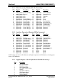
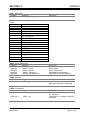
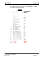
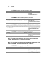
8.1.1. Main Connector (Standard 28 Pin Connector)
Pin
1
2
3
4
5
6
7
8
9
10
11
12
13
13
Signal
Function
Pin
Signal
Function
Analog Output
Analog Output
Analog Output
Analog Output
Analog Output
Digital Output
Digital Output
Digital Output
Digital Output
Digital Output
Digital Output
Digital Input
Digital Input
Digital Input
Ground (Analog)
Realtime
NO
NOx
NO2
Ground (Digital)
Sense AutoRange
Sense Range 1
Sense Range 2
Sense Range 3
Sense Range 4
Set Auto Range
Control Range 1
Control Range 2
15
16
17
18
19
20
21
22
23
24
25
26
27
28
Digital Input
Digital Input
Digital Input
Digital Input
Digital Input
Digital Input
Digital Input
Digital Input
Digital Output
Digital Output
Digital Output
Digital Output
Digital Output
Digital Output
Control Range 3
Control Range 4
Auto Cal
Calibrate
Zero
Span
Pump
Zero Gas Flow
Span Gas Flow
Sample Gas Flow
Local/Remote
Read Cal Mode
Reserved
Reserved
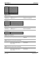
8.1.2. Auxiliary Connector (Standard 28 Pin Connector)
Pin
1
2
3
4
5
6
7
8
9
10
11
12
13
13
Signal
Function
Pin
Signal
Function
Analog Input
Analog Input
Analog Input
Analog Input
Analog Input
Digital Output
Digital Output
Digital Output
Digital Output
Digital Output
Digital Output
Digital Input
Digital Input
Digital Input
Ground
External Analog 1
External Analog 2
Spare Analog
Spare Analog
Ground (Alarm)
General Alarm
Ch 1 Conc Alarm
Ch 2 Conc Alarm
Reserved
Reserved
Reserved
Reserved
Reserved
15
16
17
18
19
20
21
22
23
24
25
26
27
28
Digital Output
Digital Output
Digital Output
Digital Output
Digital Output
Digital Output
Digital Output
Digital Output
Digital Input
Digital Input
Digital Input
DI/DO
DI/DO
DI/DO
Ground (Alarm)
Calibrate Alarm 1
Reserved
Reserved
Reserved
Read Wet Mode
Read Overflow
Read NO Mode
Set Wet Mode
Set Overflow Mode
Set NO Mode
Spare
Spare
Spare
NOTE: Analog outputs 0-10 VDC Maximum and Digital outputs are 0-5 VDC Maximum. Analog inputs
are 0-10 VDC Maximum.
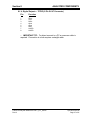
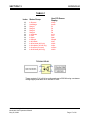
8.1.3. Digital Outputs – RS-232 (Standard 9 Pin DIN Connector)
Pin
Function
1
2
3
4
5
6
7
8
9
DCD Carrier Detect
RxD Receive Data
TxD Transmit Data
DTR Data Terminal Ready
Ground
DSR Data Set Ready
RTS Ready to Send
CTS Clear to Send
RI Ring Indicator
California Analytical Model 600 CLD C_ETL_US/CE
Rev12
Operators Manual
Page 36 of 81
Section 8
ANALYZER COMPONENTS
8.1.4. Digital Outputs – TCP/IP (8 Pin RJ-47 Connector)
Pin
Function
1
2
3
4
5
6
7
8
TDX+
TDXRXD+
Open
Open
RXDLNLED
LNLED
+ IMPORTANT TIP: For direct connect to a PC a crossover cable is
required. Connection to a hub requires a straight cable.
California Analytical Model 600 CLD C_ETL_US/CE
Rev12
Operators Manual
Page 37 of 81
Section 8
ANALYZER COMPONENTS
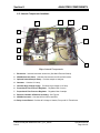
8.2. Internal Component Locations
4
3
10
8
5
6
9
2
7
1
Major Internal Components
1. Electronics: Includes instrument electronics. (See Main Electronic Board)
2. NO/NOx Solenoid Valve: Switches flow between the NO and NOx mode.
3. Optional Internal Sample Pump: Provides sample to analyzer.
4. Ozonator: Contains UV Lamp.
5. Ozonator High Voltage Supply: Produces High Voltage to UV lamp.
6. Proportional Flow Pressure Regulator: Regulates flow of ozone.
7. Proportional Flow Pressure Regulator: Regulates flow of sample.
8. Reaction Chamber & Detector Assembly: See Figure 8.
9. NO/NOx Converter: Converts NO2 to NO for total NOx
10. Relay Control Board: Provides AC Voltage to Heaters, Pump and UV Transformer.
California Analytical Model 600 CLD C_ETL_US/CE
Rev12
Operators Manual
Page 38 of 81
Section 8
ANALYZER COMPONENTS
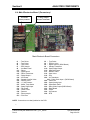
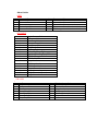
8.3. Main Electronics Board (Potentiometers)
RP1 to RP17
RP18
Main Electronic Board Potentiometers
RP1
RP2
RP3
RP4
RP5
RP6
RP7
RP8
RP9
:
:
:
:
:
:
:
:
:
EPC 9.5V Sample Set
EPC 9.5V Air Set
O3 Cutoff
Cell Temp Set
Oven Temp Set
Pump Temp Set
Converter Temp Set
O2 Temp Set
NH3 Temp Set
RP10 : Chiller Zero Temp Set
RP11 : Chiller Span Temp Set
RP12 : Chiller Temp Set
RP13 : 12VDC Adjust
RP13 : Sample Pressure Set
RP15 : Air Pressure Set
RP16 : Not Used
RP17 : Not Used
RP18 : Coarse Zero Adjust
NOTE: Potentiometers are clearly labeled on both sides of the PCB.
California Analytical Model 600 CLD C_ETL_US/CE
Rev12
Operators Manual
Page 39 of 81
Section 8
ANALYZER COMPONENTS
8.4. Main Electronics Board (Connectors)
Test Points
Clearly Labeled
Voltage Output
Resistor Stand Offs
Main Electronic Board Connectors
J1
J3
J5
J7
J9
J11
J13
J15
J17
J19
J21
J23
J25
J27
J29
J31
J33
J35
J37
JP1
:
:
:
:
:
:
:
:
:
:
:
:
:
:
:
:
:
:
:
:
Test Points
Test Points
Test Points
EPC Sample
Aux Back Panel
Diluter
Digital Input 2
Diluter Transducer
Digital Output 1
Aux Power
Sample Overflow Valve
Wet/Dry Valve
+ 5 Volt Detector
Chiller Temp Sense
Spare Digital Input
Fan Power
Chiller Power
Detector
Thermocouple
PGA Zero
J2
J4
J6
J8
J10
J12
J13
J16
J18
J20
: Test Points
: EPC Air Valve
: Digital Output 2 (DIDO Board)
: Sample Transducer
: Spare Digital Output
: Main Back Panel
: NO/NOx Valve
: Span Valve
: Zero
: Air Transducer
J22 : Daisy Chain Input 1 (DIDO Board)
J24 : Chiller Out
J26 : Spare Analog Input
J28 : Spare Back Panel
J30 : Daisy Chain Output (DIDO Board)
J32 : Relay Board
J34 : Power
J36 : O2 Detector
J38 : RTD
NOTE: Connections are clearly labeled on the PCB
-California Analytical Model 600 CLD C_ETL_US/CE
Rev12
Operators Manual
Page 40 of 81
Section 8
ANALYZER COMPONENTS
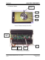
8.5. Reaction Chamber
To Pressure
Transducer
Exhaust
Sample
Ozone
Reaction Chamber Assembly (Oven Side)
Inverting
Amplifier
Adjust
Power
Input
Main Board
Connection
Gain
Adjust
Zero
Adjust
Reaction Chamber Pre-Amplifier
California Analytical Model 600 CLD C_ETL_US/CE
Rev12
Operators Manual
Page 41 of 81
Section 8
ANALYZER COMPONENTS
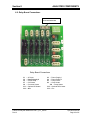
8.6. Relay Board Connections
J32 – Connects to Main
Electronic Board J32
Relay Board Connections
J1
J3
J5
J7
J9
J11
J13
:
:
:
:
:
:
:
AC Input
Power Supply 2
Ozone Lamp
Cell Heater
Converter Heater
Optional O2 Heater
Aux
California Analytical Model 600 CLD C_ETL_US/CE
Rev12
J2
J4
J6
J8
: Power Supply 1
: Power Supply 3
: Pump Power
: Oven Heater
J10 : Pump Heater
J12 : Optional NH3 Heater
J13 : Aux
Operators Manual
Page 42 of 81
Section 11
REACTION CHAMBER
9. Operation
9.1. Preparation for Operation
Check that the external plumbing and wiring have been connected correctly, as described
in this manual.
NOTE: The internal ozone generator requires approximately 1 hour of continuous
operation for the analyzer to achieve full zero and span calibration stability.
9.2. Operation
1. Power On: Turn ON the power switch on the rear panel. The digital display should
illuminate.
2. Introduce Ozone Supply (Air or O2): Adjust the cylinder output pressure to 25
PSIG. The internal air pressure is factory set to deliver the air pressure required for
optimum analyzer performance as indicated in the factory settings screen.
3. Air or O2 Pressure Settings: Check the air pressure setting by referring to the
diagnostic screen to check air pressure. The pressure should read as indicated in the
factory settings screen.
4. Zero Adjustment: Flow zero gas through the instrument by selecting the calibration
screen and select either manual or auto calibrate. NOTE: The instrument may also
be operated by an external computer or by remote contact closures.
5. Span Adjustment: Flow span gas through the instrument by selecting the calibration
screen and select either manual or auto calibrate.. NOTE: The instrument may also
be operated by an external computer or by remote contact closures.
NOTE: The correct calibration gas values must be entered. The instrument is available
from the factory with four ranges.
6. NO/NOx Function: The analyzer switches the NOx converter in and out of the
sample stream and is controlled from the measurement screen. In the NO mode, the
sample bypasses the converter and the resultant analysis produces the value of NO
(Only) in the sample. In the NOx mode, the sample passes through converter and the
resultant analysis produces the value of NOx (NO + NO2) in the sample. The
analyzer will also display the values of NOx, NO and NO2. The NO mode may be
switched in and out remotely by a contact closure or computer. Remote control
wiring is terminated in the rear panel connector. (See Appendix).
California Analytical Model 600 CLD C_ETL_US/CE
Rev12
Operators Manual
Page 43 of 81
Section 11
REACTION CHAMBER
7. Sample Pressure Check: With sample gas flowing through the instrument, check
the sample pressure setting by referring to the diagnostic screen. The sample
pressure should read as indicated in the factory pressure settings screen.
8. Sample Pump: If the analyzer is supplied with the optional internal sample pump, it
is always on in the measure mode. It is turned off during calibration and may be
manually turned off by putting the analyzer in standby.
9. Sample Line: Make certain the sample line is flushed before connecting to the
analyzer sample inlet.
10. Instrument Power: Turn instrument power on and allow the reaction chamber and
NOx converter to stabilize before turning on the sample pump and/or connecting the
sample line.
11. Sampling System: Prepare and check the sample system. Check the sample
pressure as indicated in the factory settings screen.
12. Air or O2 Pressure: Check the Air/O2 pressure for proper setting as indicated in the
factory setting screen. Readjust internal pressure as required. Note: Cylinder
pressure should be set at 25 PSIG.
13. Zero & Span Calibration: Zero and span adjustment should be checked every 24
hours by either manual or automatic calibrations.
14. Reaction Chamber Assembly: Dust, water droplets, or mist entering the reaction
chamber assembly may cause drift due to contamination. If the calibration
procedures fails to bring the instrument to zero, check the chamber for contamination.
9.3. Shut Down Procedure
1. Turn off the zero, span and air/O2 cylinders.
2. If the analyzer contains the optional internal sample pump, disconnect the sample line
from the rear inlet port. Do NOT turn off the sample pump or analyzer power at this
point.
3. Allow the analyzer to draw in room air for approximately 5 minutes, or flush out any
remaining sample which may cause condensation as the analyzer cools.
4. Turn off the optional internal sample pump by setting the analyzer to standby.
5. Turn off the analyzer power.
6. Back-flush the sample line (and filter) of any sample before disconnecting and
powering down.
California Analytical Model 600 CLD C_ETL_US/CE
Rev12
Operators Manual
Page 44 of 81
Section 11
REACTION CHAMBER
10. Functional Description
10.1. Operating Principle
The California Analytical Model 600 CLD Analyzer utilizes the chemiluminescent method
of determination of oxides of nitrogen (NO or NOx) in a sample gas. In the NO mode, the
NO in the sample is quantitatively converted to NO2 by gas phase oxidation with
molecular ozone produced by the UV reaction of cylinder air. Generally, 10 to 15 percent
of these NO2 molecules are elevated to an electronically-excited state. This reaction is
immediately followed by reversion to a non-excited state and emission of photons. The
photons impinge on a photodiode detector (PHOTODIODE) which generates a low DC
current directly proportional to the NO contained in the sample gas. This current is
amplified by a precision electrometer and presented to digital panel meter and recorder
output. In the NOx mode, the sample is first routed to the NOx converter where the NO2
component is reduced to NO. The complete sample is analyzed by the PHOTODIODE
as above.
10.2. Reaction Chamber
The sample and ozone are delivered to the reaction chamber via the unique regulated
flow system described below. The sample and ozone are mixed together at the center of
the chamber where the reaction takes place. The sample is vented from the chamber
through a 1/8 inch stainless steel tube. The chamber contains a red filter which is sealed
with an integral O Ring. The chamber assembly is O Ring mounted to the
PHOTODIODE. The complete chamber and PHOTODIODE assembly is housed in an
RFI shielded enclosure.
10.3. Flow System
The basic function is to deliver highly regulated flows of sample and air or O2 to the
ozonator and reaction chamber assemblies. The EPC valve delivers approximately 15
PSIG to a pre-set capillary and consequently accurately predetermines the ozone flow
rate. The air supply cylinder should be set to 25 psig. The sample is presented to the
reaction chamber via a precision, factory set electronically controlled proportional
pressure valve through a capillary. This pressure is factory set at approximately 3.85
PSIG. A close coupled bypass capillary minimizes "dead volume" and improves
response time. Sample inlet pressure and regulated air pressures are monitored by
internal pressure transducers and presented in PSIG via the diagnostics screen. NOTE:
The correct pressures are determined by the factory for optimum analyzer performance
and measured by N.I.S.T. traceable standards. They are recorded on the Factory
Settings Screen.
California Analytical Model 600 CLD C_ETL_US/CE
Rev12
Operators Manual
Page 45 of 81
Section 11
REACTION CHAMBER
10.4. Main Electronics Board
The main electronics board contains the instrument power supplies and required
instrument electronics. A single transformer provides power to the main circuit board and
includes provisions for 110/220 VAC at 50/60 Hz input.
10.5. Relay Board
The relay circuit board contains the logic circuitry required to control and switch the AC
power to the required heaters and sample pump.
11. Reaction Chamber
11.1. Disassembly Procedure
a. Shut off ALL gas flow.
b. Remove power from the instrument.
c. Remove the top cover retaining screws.
d. Remove all 4 tubes from the 4 way cross.
e. Remove the 4 screws securing the photodiode and reaction chamber from the oven.
f.
Remove the photodiode electrical connector from the main circuit board.
g. Remove the chiller connection from the photodiode/reaction chamber.
h. Separate the photodiode and heat sink assembly from the reaction chamber by
removing the 4 Allen screws from the front of the heat sink. Save the 2 black rubber
“O” rings.
i. Separate the mounting plate and the glass filter from the reaction chamber. Save the
2 Teflon spacers and “O” ring.
j. Separate the manifold from the gold reaction chamber. NOTE the position of the holes
in the Teflon gasket relative to the assembly screw holes. The large hole is ozone.
11.2. Assembly Procedure
a. Wash the reaction chamber glass filter and manifold separately in detergent using a
test tube brush. Be careful of the sample tube in the manifold. Do not use abrasives.
b. Dry by blowing clean with dry nitrogen.
c. Reassemble the chamber assembly in reverse order per the above. Make certain the
sample tube is centered when assembling the manifold to the reaction chamber.
California Analytical Model 600 CLD C_ETL_US/CE
Rev12
Operators Manual
Page 46 of 81
SECTION 13
APPENDIX
12. Troubleshooting
12.1. Ozone Air/O2 Supply
The Air/O2 flow is controlled by an EPC valve. It requires 25 psig cylinder supply pressure
and is factory set to deliver approximately 10 to 20 psig to the ozone capillary. This pressure
may be monitored by the diagnostics display. The flow rate from the capillary is very low and
will require a bubble flow meter to accurately determine proper flow.
12.2. Sample Supply
The sample flow is controlled by an adjustable electronic proportional pressure valve. This
valve requires a 10 to 25 PSIG sample supply pressure to deliver the proper pressure to the
sample capillary. This pressure may be monitored by the diagnostics meter at any time after
inlet sample has been applied. The sample flow rate from the capillary is very low and will
require a bubble flow meter to determine proper flow rate. If the pressure is properly set, and
a clogged capillary is suspected, replace the sample capillary.
NOTE: If the analyzer contains an optional internal sample pump, the introduction of a
pressurized sample gas in excess of 1.5 PSIG will damage the pump.
12.3. NO/NOx Converter
Several published test procedures require periodic NOx efficiency tests to be performed on the
converter to determine NO2 to NO conversion efficiency utilizing a NOx generator. The CAI
Model NOxGen may be used for this procedure. A short test using NO2 calibration gas is also
defined in the U.S Federal Register, Title 40, Part 86.332.79 (e).
13. Drawings
13.1. AK Protocol
13.2. Rear Panel Connections
13.3. Flow Diagram
13.4. Block Electrical Drawing
California Analytical Model 600 CLD C_ETL_US/CE
March 2006
Operators Manual
Page 47 of 85
SECTION 13
APPENDIX
13.1 Serial Interface and AK-Commands
The serial interface enables remote control of the Model 600 analyzer by a master computer. It is
implemented as an RS232 V24 interface and meets all requirements of the AK protocol.
A 9-pin male connector at the back of the unit is used to connect a master computer with the
following pin assignment:
Pin 3 = Txd (transmit)
Pin 2 = Rxd (receive)
Pin 5 = Gnd (ground)
Interface Parameters
Baud rate:
Data bits:
Stop bit:
Don't care:
Parity:
XON/XOFF:
9600, 4800, 2400, 1200, 600, 300 baud
7 or 8
1 or 2
1 byte, adjustable (e.g. 32)
Even, odd, none
Active or not active
General AK Requirements
1) If the command message contains no error, the acknowledge message contains the echo of
the function code and the error status number (1 to 9).
2) If the transfer was faulty or the function code unknown, the answer contains four question
marks (example. "???? 0").
3) If the displayed value is not valid, a "#" is placed in front of the measured value (example:
"AIKG 0 #9999").
4) If a control or adjusting command is sent via the serial interface while the measuring device is
in "Manual" mode, it sends an answer like "SLIN 0 K0 OF".
5) If a channel does not exist, the answer for control and adjusting commands is e.g. "ATEM 0 3
NA" in which 3 is the number of the sub-channel.
6) If the device is busy with a running function (SLIN, for example), every arriving control
command is ignored (except SRES and STBY); and the response message is e.g. "SMAN 0
BS. If In the mode "SINT" an additional "SINT KO" command is received, the integrator is
reset to 0 and the integration is restarted.
7) If the command message contains data that the measuring device cannot process ("ESYZ K0
ABC", for example), the response message is "ESYZ 0 SE". A syntax error is recognized if the
data does not match the expected format or if the parameters do not fit the expected size.
8) Numbers are in floating-point format with decimal point. The decimal point can be dropped for
integers.
9) If you switch from "Manual" to "Remote" at the device, it remains in "Manual" mode until a
"SREM K0" is received by the control computer. On the display, this mode is indicated by
REME" (Remote enable) on the status line. In manual mode, query commands via the serial
interface are possible at any time.
California Analytical Model 600 CLD C_ETL_US/CE
March 2006
Operators Manual
Page 48 of 85
SECTION 13
APPENDIX
AK Protocol Format
The master computer and the Model 600 analyzer communicates via the RS232 serial link. The
Model 600 analyzer acts as a “slave" and only responds to commands.
Serial Interface Parameters:
1)
2)
3)
4)
Baud from 300 to 9600 bps, can be selected via the display.
7or 8 data bits, 1 or 2 stop bits, and the parity (yes/no).
The data transmission is full duplex (no echo) with XON/XOFF protocol.
The "don't-care" byte" (byte 2) is adjustable (factory setting 20H).
Command Format:
<STX>
don't care
function code
space 20H
channel N°
space
data
<ETX>
02H Example: ASTZ K0
any byte (default 20H)
code 4 byte long (e.g., ASTZ)
20H
always "K0" for the analyzer
20H (onIy if followed by data, otherwise <ETX> )
data bytes (depending on the command)
03H
Answer Format:
<STX>
don't care
function code
space
status
space
data
<ETX>
02H Example: STZ 0 SREM STBY
adjustable, factory setting 20H
same code as command package (e.g., ASTZ)
20H
0 without error or 1 to 9 when error (see also ASTF command)
20H (onIy if followed by data, otherwise <ETX> )
parameter (depending on the command)
03H
Scans
AKON: Measured concentration value
Command
Response
_AKON_K0
_AKON_s_z.z_y.y_x.x_w.w
California Analytical Model 600 CLD C_ETL_US/CE
March 2006
Description
Measured concentration value is
responsed
z.z:current Measured Value
y.y:NO
x.x: NO2
w.w:Nox
y.y,x.x,w.w are only used in dual
measure mode. Otherwise “O.O“ will
be returned
Operators Manual
Page 49 of 85
SECTION 13
APPENDIX
AEMB: Set measuring range
Command
Response
_AEMB_K0
_AEMB_s_Mn
Description
Current measuring range is responsed
AMBE: Measuring range limit
Command
Response
_AMBE_K0
_AMBE_s_M1_w.w_M2_x.x_M3_y.y_
M4_z.z
_AMBE_K0_Mn _AMBE_s_Mn_z.z
Description
All existing measuring range limits are
responsed
Range limit of Range Mn is responsed
AKAK: Calibration gas concentrations
Command
Response
AKAK_K0
_AKAK_s_M1_w.w_M2_x.x_M3_y.y_
M4_z.z
AKAK_K0_Mn
AKAK_s_Mn_z.z
Description
All existing calibration gas values are
responsed
Calibration gas value of Range Mn is
responsed
AMBU: Upper and lower range switchover values for autorange
Command
Response
Description
_AMBU_K0
_AMBU_s_M1_w.w_W.W_M2_x.x_X.
Lower and upper range switchover
X_M3_y.y_Y.Y_M4_z.z_Z.Z
value of autorange are responsed
ASTZ: Normal device status
Command
Response
_ASTZ_K0
_ASTZ_s_SREM_STBY__SENO_SARE
_SDRY
Possible states:
SREM:
remote
SMAN:
manual
STBY:
standby
SPAU:
pause
SMGA:
measuring gas
SNGA:
zero gas
SEGA:
end gas
SATK SNGA:
zero gas during
autocal
SATK SEGA:
end gas during autocal
SLIN:
For compatibility only
SSPL:
purging
SKOP:
measure
SENO:
NO mode
SMAN:
NOx mode
California Analytical Model 600 CLD C_ETL_US/CE
March 2006
Description
Device status is responsed
SARE:
Autorange on
SARA:
Autorange off
SDRY:
Chiller on
SWET:
Chiller off
Operators Manual
Page 50 of 85
SECTION 13
APPENDIX
ASTF: Error status
Command
Response
_ASTF_K0
_ASTF_s_f1_f2_f3_.._f15
Description
Current error number is responsed
Errors:
1
2
3
4
5
6
7
8
9
10
11
12
13
13
15
16
17
18
Sample Pressure Failure
Air Pressure Failure
Oven Temp Failure
Converter Temp Failure
Pump Temp Failure
Diode Temp Failure
Cell Temp Failure
Peltier Gas Temp Failure
Reaction Chamber Temp Failure
EPC Coil Sample Failure
EPC Coil Air Failure
Range Overflow
ADC Range Overflow
ADC Range Underflow
Range 1 is not calibrated
Range 2 is not calibrated
Range 3 is not calibrated
Range 4 is not calibrated
AKEN: Device identification
Command
Response
_AKEN_K0
_AKEN_s_devicename
_AKEN_K1
_AKEN_s_model
_AKEN_K2
_AKEN_s_serialno
_AKEN_K3
_AKEN_s_airpressure
_AKEN_K4
_AKEN_s_samplepressure
ARMU: Rawvalue
Command
Response
_ARMU_K0
_ARMU_s_z.z
ATEM: Temperatures
Command
Response
_ATEM_K0
_ATEM_s_z.z_y.y_...
_ATEM_K0_x
_ATEM_s_z.z
California Analytical Model 600 CLD C_ETL_US/CE
March 2006
Description
Device identification is responsed
Device model
Device serial number
Suggested input air pressure
Suggested input sample pressure
Description
Raw value before linearization and
offset-span-correction is responsed
Description
All Temperatures in degrees celsius
are responsed
Temperature of x in degrees celsius is
responsed
Operators Manual
Page 51 of 85
SECTION 13
APPENDIX
Description of x:
X
CLD
1
Oven Temp
2
Converter Temp
3
Pump Temp
4
Diode Temp
5
Cell Temp
6
Peltier Temp
7
Reaction Chamber Temp
ADRU: Pressures
Command
Response
_ADRU_K0
_ADRU_s_z.z_y.y_...
_ADRU_K0_x
_ADRU_s_z.z
Description of x:
1
2
3
4
Sample Pressure
Air Pressure
Sample EPC Coil Voltage
Air/Ozone EPC Coil Voltage
ADUF: Flows
Command
_ADUF_K0
_ADUF_K0_x
Response
_ADRU_s_z.z_y.y_...
_ADRU_s_z.z
Description
All pressures are responsed
Pressure of x is responsed
Description
All flows are responsed
Flow of x is responsed
Description of x:
1
Sample Flow
2
Air Flow
AGRD: Polynom coefficients
Command
Response
_AGRD_K0_Mn _AGRD_s_Mn_a0_a1_a2_a3_a4
Description
Polynom coefficients of range Mn are
responsed
AANG: Deviation from zero point after autocalibration
Command
Response
_AANG_K0
_AANG_s_M1_z.z_da_dr_
M2_z.z_da_dr_ M3_z.z_da_dr_
M4_z.z_da_dr_
Description
Deviation from zero point after
autocalibration
AAEG: Deviation from end point after autocalibration
Command
Response
_AAEG_K0
_AANG_s_M1_z.z_da_dr_
M2_z.z_da_dr_ M3_z.z_da_dr_
M4_z.z_da_dr_
Description
Deviation from end point after
autocalibration
California Analytical Model 600 CLD C_ETL_US/CE
March 2006
Operators Manual
Page 52 of 85
SECTION 13
California Analytical Model 600 CLD C_ETL_US/CE
March 2006
APPENDIX
Operators Manual
Page 53 of 85
SECTION 13
APPENDIX
AFDA: Purge and Autocalibration times
Command
Response
_AFDA_K0_SATK _AFDA_s_z_y_x_w_Z.Z
_AFDAKO_SSPL
AFDA_s_z.z
APAR: Request Autocalibration tolerance values
Command
Response
_APAR_K0_SATK _APAR_s_z.z_y.y_x.x_w.w
AKAL: Deviations from calibration
Command
Response
_AKAL_K0_
_AKAL_s_M1_z.z_y.y_x.x_w.w
_AKAL_s_M2_z.z_y.y_x.x_w.w
_AKAL_s_M3_z.z_y.y_x.x_w.w
_AKAL_s_M4_z.z_y.y_x.x_w.w
ASYZ: Respond System Time
Command
Response
_ASYZ_K0_
_ASYZ_s_yymmdd_hhmmss
AT90: Respond Lowpass filter time
Command
Response
_AT90_K0_
_AT90_s_t
ADAL:Diagnostic alarm limits
Command
Response
_ADAL_K0
_ADAL_s_a1.min_a1.max_.._f12.max
_ADAL_K0_x
_ADAL_s_x.min_x.max
California Analytical Model 600 CLD C_ETL_US/CE
March 2006
Description
Autocalibration times:
z: Purge time
y: Calibration time
x: Total Calibration time
w: Verify time
(z,y,x,w in seconds)
Purge time will be responded
Description
Autocalibration tolerance value(%):
z.z: Range 1
y.y: Range 2
x.x: Range 3
w.w: Range 4
Description
Deviation (ppm):
z.z: Zero gas relative to last
calibration
y.y: Zero gas factory calibration
x.x: Span gas relative to last
calibration
w.w: Span gas factory calibration
Description
Respond system time
yymmdd:year, month,day (each 2
characters wide, no spaces)
hhmmss:hour,minutes,seconds)
Description
Respond lowpass filter time
t=filter time in seconds
Description
All alarms are responded
Alarm limits of x
Operators Manual
Page 54 of 85
SECTION 13
Alarm Limits:
1
2
3
4
5
6
7
8
9
10
11
12
APPENDIX
Sample Pressure
Air Pressure
Oven Temp
Converter Temp
Pump Temp
Diode Temp
Cell Temp
Peltier Gas Temp
EPC Coil Sample Voltage
EPC Coil Air/Ozone Voltage
Reserved
Sample Content
ATCP: Query TCP/IP settings
Command
Response
_ATCP_K0
_ATCP_s_zzz.zzz.zzz.zzz
_ATCP_s_yyy.yyy.yyy.yyy
_ATCP_s_xxxx
AENT: Query calibration gas flow setting
Command
Response
_AENT_K0
_AENT_s_x
Description
zzz: TCP/IP Address
yyy: TCP/IP subnet mask
xxxx: TCP/IP port
Description
x=10: Calibration through sample gas
inlet (pump)
y=11: Calibration through zero/span
valves
Control commands
SRES: Reset
Command
_SRES_K0
Response
_SRES_s
Description
Reset
SPAU: Pause
Command
_SPAU_K0
Response
_SPAU_s
Description
Pause mode
STBY: Standby
Command
_STBY_K0
Response
_STBY_s
Description
Standby mode
California Analytical Model 600 CLD C_ETL_US/CE
March 2006
Operators Manual
Page 55 of 85
SECTION 13
APPENDIX
SNGA: Open valve for zero gas calibration
Command
Response
_SNGA_K0
_SNGA_s
_SNGA_K0_Mn
_SNGA_s
SEGA: Open valve for end gas calibration
Command
Response
_SEGA_K0
_SEGA_s
_SEGA_K0_Mn
_SEGA_s
SSPL: Purge Analyzer with zero gas
Command
Response
_SSPL_K0
_SSPL_s
SLIN: Linearization mode
Command
Response
_SLIN_K0
_SLIN_s
SKOP: Converter Check
Command
Response
_SKOP_K0
_SKOP_s
Description
Open valve for zero gas calibration of
actual measuring range
Open valve for zero gas calibration of
range Mn
Description
Open valve for end gas calibration of
actual measuring range
Open valve for end gas calibration of
range Mn
Description
Open valve for zero gas and purge the
analyzer
Description
Change status to SLIN
(only for compatibility)
Description
Change status to SKOP and activate
sample pump
(only for compatibility)
SWET: Chiller off – Wet mode measuring
Command
Response
_SWET_K0
_SWET_s
Description
Switch chiller off
SDRY: Chiller on – Dry mode measuring
Command
Response
_SDRY_K0
_SDRY_s
Description
Switch chiller on
SATK: Start automatic calibration
Command
Response
_SATK_K0
_SATK_
_SATK_K0_Mn
_SATK_s
California Analytical Model 600 CLD C_ETL_US/CE
March 2006
Description
Start automatic calibration of all
ranges
Start automatic calibration using range
Mn
Operators Manual
Page 56 of 85
SECTION 13
SEMB: Set measuring range
Command
Response
_SEMB_K0_Mn _SEMB_s
SARE: Auto range on
Command
Response
_SARE_K0
SARE_s
SARA: Auto range off
Command
Response
_SARA_K0
_SARA_s
APPENDIX
Description
Set measuring range
Autorange is disabled
Description
Set auto range on
Description
Set autorange off
SREM: Remote mode for AK-commands
Command
Response
_SREM_K0
_SREM_s
Description
Set device in remote mode
SMAN: Manual control to control device manually
Command
Response
_SMAN_K0
_SMAN_s
Description
Set device in manual mode
SMGA: Start measuring
Command
Response
_SMGA_K0
_SMGA_s
SNKA: Saves measured value as new offset.
Command
Response
_SNKA_K0
_SNKA_s
SEKA: Saves measured value as new span value
Command
Response
_SEKA_K0
_SEKA_s
SENO: Converter off
Command
Response
_SENO_K0
_SENO_s
California Analytical Model 600 CLD C_ETL_US/CE
March 2006
Description
Start measuring
Turn on pump for sample gas
Description
Saves measured value of actual range
as new offset if zero valve is opened
Description
Saves measured value of actual range
as new span value if span valve is
opened
Description
Set converter off
Only NO is measured
Operators Manual
Page 57 of 85
SECTION 13
SNOX: Converter on
Command
Response
_SNOX_K0
_SNOX_s
APPENDIX
Description
Set converter on
All kinds of NOx are measured
SNO2: Converter on
Command
Response
_SNO2_K0
_SNO2_s
Description
Activates dual measure mode.
Analyzer switches periodically
between NO and NOx mode and
displays NO, NO2, NOx
SFGR: Reset calibration settings to factory defaultConverter on
Command
Response
Description
_SFGR_K0
_SFGR_s
Reset all calibration settings to their
factory settings
SENT: Set calibration gas flow
Command
Response
_SENT_K0_x
_SENT_s
Description
x=10: Calibration through sample gas
inlet (pump)
y=11: Calibration through zero/span
valves
Settings
EKAK: The four span gas concentration values are set
Command
Response
_EKAK_K0_M1_w.w_M2_x.x_M3_y.y_M4_z.z _EKAK_s
Description
Set end gas values
EMBE: The four measuring range end values are set
Command
Response
Description
_EMBE_K0_ M1_w.w_M2_x.x_M3_y.y_M4_z.z
_EMBE_s Set range limits
EMBU: The upper and the lower range switchover for autorange are set
Command
Response Description
_EMBU_K0_M1_w.w_W.W_M2_x.x_X.X_M3_y.y _EMBU_s Set lower and upper range
_Y.Y_M4_z.z_Z.Z
switchover limits
California Analytical Model 600 CLD C_ETL_US/CE
March 2006
Operators Manual
Page 58 of 85
SECTION 13
APPENDIX
EKEN: Set new device identification
Command
_EKEN_K0_new device-name
Response
_EKEN_s
Description
Set new device identification
Maximum length of device name
are 40 characters
NOTE: To change device identification, you must first rename the device to “RESET”.
Now a name up to 40 letters can be given.
NOTE: The device name must not have any blanks between, f.e. “CAI CLD” is not allowed. You can use
undersline, i.e. “CAI_CLD”.
EGRD: Set polynom coefficients
Command
_EGRD_K0_Mn_a0_a1_a2_a3_a4
EFDA: Set autocalibration and purge times
Command
Response
_EFDA_K0_SATK_z_y_x_w
_EFDA_s
_EFDA_K0_SSPL_z
_EFDA_s
EPAR: Set autocalibration tolerance values
Command
Response
_EPAR_K0_SATK_z.z_y.y_x.x_w. _EPAR_s
w
Response
_EGRD_s
Description
Set polynom coefficients of range
Mn
Description
Set autocalibration times:
z= Purge time
y=Calibration time
x=Total calibration time
w=Verify time
(z,y,x,w in seconds)
Set analyzer purge time to z seconds
Description
Autocalibration Tolerance value (%):
z.z= Range 1
y.y= Range 2
x.x= Range 3
w.w= Range 4
ESYZ: Set System Time
Command
_ESYZ_K0_yymmdd_hhmmss
Response
_ESYA_s
Description
Respond system time:
yymmdd:year, month,day (each 2
characters wide, no spaces)
hhmmss:hour,minutes,seconds)
ET90: Set Lowpass Filter Time
Command
_ET90_K0_t
Response
_ET90_s
Description
Set lowpass filter time:
t= filter time in seconds
California Analytical Model 600 CLD C_ETL_US/CE
March 2006
Operators Manual
Page 59 of 85
SECTION 13
APPENDIX
EDAL:Diagnostic alarm limits
Command
_EDAL_K0_a1.min_a1.mas_..._a12max
_EDAL_K0_x_x.min_xmax
Alarm Limits:
1
2
3
4
5
6
7
8
9
10
11
12
Response
_EDAL_s
_EDAL_s
Description
Set all alarm limits
Set alarm limits of x
Sample Pressure
Air Pressure
Oven Temp
Converter Temp
Pump Temp
Diode Temp
Cell Temp
Peltier Gas Temp
EPC Coil Sample Voltage
EPC Coil Air/Ozone Voltage
Reserved
Sample Content
ETCP: Set TCP/IP Parameters
Command
_ETCP_K0_zzz.zzz.zzz.zzz
_ETCP_K0__yyy.yyy.yyy.yyy
_ETCP_K0_xxxx
Response
_ETCP_s
Description
zzz= TCP/IP address
yyy= TCP/IP subnet mask
xxxx= TCP/IP port
All changes take effect after next
power on cycle
Abbrevations used
Mn
M1 .. M4
w.w .. Z.Z.
x
t
a0 .. a4
s
yyymmdd
hhmmss
: Measuring range number
: Measuring Range 1 .. 4
: Numerical value
: Number
: Numeric integer value
: Polynom coefficients
: Status
: Date of format year, month and day with 2 characters each and no spaces
: Time of format hour, minute and second with 2 characters each and no spaces
California Analytical Model 600 CLD C_ETL_US/CE
March 2006
Operators Manual
Page 60 of 85
SECTION 13
APPENDIX
13.2 Rear Panel Connectors
28 Pin Main Connector Assignments:
Signal
Type
28 Pin Auxiliary Connector Assignments:
Signal
A Input
A Input
2
3
External Analog 1
External Analog 2
A Input
4
Spare analog
A Output
Analog
pin #
1 GND (analog)
Realtime 0-10 VDC
2 Maxi,um
3 NO 0-10 VDC Maximum
NOx 0-10 VDC
4 Maximum
NO2 0-10 VDC
5 Maximum
A Input
5
Spare analog
D Output
D Output
D Output
D Output
D Output
D Output
D Input
D Input
D Input
D Input
D Input
D Input
D Input
D Input
D Input
D Input
D Output
D Output
D Output
D Output
D Output
D Output
Digital
6 GND (Digital)
7 Sense AutoRange
8 Sense Range 1
9 Sense Range 2
10 Sense Range 3
11 Sense Range 4
12 Set AutoRange
13 Control Range 1
13 Control Range 2
15 Control Range 3
16 Control Range 4
17 Auto Cal
18 Calibrate
19 Zero
20 Span
21 Pump
23 Span Gas Flow
24 Sample Gas Flow
25 Local/Remote
26 Read Cal Mode
27 Reserved
28 Reserved
Alarms
D Output
D Output
D Output
D Output
D Output
D Output
D Output
D Output
D Output
D Output
D Output
D Output
D Output
D Output
D Output
D Output
D Input
D Input
D Input
DI/DO
DI/DO
DI/DO
A Output
A Output
A Output
A Output
Type
Spare
A Input
California Analytical Model 600 CLD C_ETL_US/CE
March 2006
Analog
pin #
1
GND (analog)
Digital
6
7
8
9
10
11
12
13
13
15
16
17
18
19
20
21
23
24
25
26
27
28
GND (Alarm)
General Alarm
Ch. 1 Conc. 1 Alarm
Ch. 1 Conc. 2 Alarm
Reserved
Reserved
Reserved
Reserved
Reserved
GND (Alarm)
Calibration Alarm 1
Reserved
Reserved
Reserved
Read Wet Mode
Read OverFlow
Set Wet Mode
Set OverFlow
Set NO Mode
Spare
Spare
Spare
Operators Manual
Page 61 of 85
SECTION 13
APPENDIX
Note: All digital outputs and inputs are 0-5 VDC ONLY. All analog inputs are 0-10 VDC
ONLY. Connecting analog outputs to existing current loop systems or voltage loop
systems WILL DAMAGE the instrument.
California Analytical Model 600 CLD C_ETL_US/CE
March 2006
Operators Manual
Page 62 of 85
SECTION 13
APPENDIX
13.3 MODEL 600 CLD Flow Diagrams
NOTE: Standard Analyzer
California Analytical Model 600 CLD C_ETL_US/CE
March 2006
Operators Manual
Page 63 of 85
SECTION 13
APPENDIX
NOTE: Standard Analyzer with Optional Zero/Span Solenoids
California Analytical Model 600 CLD C_ETL_US/CE
March 2006
Operators Manual
Page 64 of 85
SECTION 13
APPENDIX
NOTE: Standard Analyzer with Optional Sample Pump
California Analytical Model 600 CLD C_ETL_US/CE
March 2006
Operators Manual
Page 65 of 85
SECTION 13
APPENDIX
NOTE: Standard Analyzer with Optional Sample Pump and Zero/Span Solenoids
California Analytical Model 600 CLD C_ETL_US/CE
March 2006
Operators Manual
Page 66 of 85
SECTION 13
APPENDIX
13.4 Electrical Block Diagram
California Analytical Model 600 CLD C_ETL_US/CE
March 2006
Operators Manual
Page 67 of 85
SECTION 13
APPENDIX
13.5 Starting With SERIAL NUNBER UO6081
1.0 INTRODUCTION
The Model 600 CLD Series Instruments starting with Serial Number U06061 have several new
Hardware and Software features.
The Hardware includes the use of a new memory system, isolation of the analog output signals
and 15 relays that are used to buffer the many new digital output signals that are now available.
The available digital signals consist of a SERVICE group, to externally monitor a number of
parameters that provide insight for preventative maintenance and diagnostics decisions.
A second STATUS group, is provided to define the operation of the instrument such as Spanning,
Zeroing, Calibrating and the Current Range (1, 2, 3, 4, AUTO).
The Software includes modifications to existing functions, changes to the Measurement screen,
additional Short-Cut Keys and several New Functions that are listed as follows:
•
MEASUREMENT
Over Range
C1/C3
Zero
Span
Range Limits
Span Values
Outputs
888888
Removed
F5
F6
F8
F9
F10
Note: The operator can use these Short-Cut Keys or continue to use existing procedures.
•
NEW FUNCTIONS
Auto Startup
ALARMS
Offsets& Gains
D/A Calibration
Cal Analog Outputs
Ignite ON Power Up
Save Data Archiving Time
User Digital Outputs
•
Modifications
Saved/Not good
Re-Set Calibration Values
California Analytical Model 600 CLD C_ETL_US/CE
March 2006
F5, F7, F7
F5, F7, (Use F6 to toggle ON/OFF)
F4, F3, F5
F5, F7, F8
F5, F8, (Use F8 to toggle ON/OFF)
F5, F8, (Use F9 to toggle ON/OFF)
F5, F7, F1, F5 (Use ENTER to change
recording time)
F5, F9
F4, F2, F1 or F2 (To flow Zero or Span Gas)
F4, F5
Operators Manual
Page 68 of 85
SECTION 13
APPENDIX
2.0 OPERATION OF MEASUREMENT KEYS
Note: The Å &Æ Keys continue to be used to view a complete list of menu items.
2.1 Over range 888888
In the Sampling mode only, any value that exceeds the “software range” by
more than10% will be displayed as 888888.
Note: If the ranges have not been modified then the original factory physical ranges
and the software ranges are the same.
2.2 Zero: Select the required range then press F5.
Note: For instruments with an internal Zero Solenoid select Calibration by
Valves. (F5, F2, F4)
Zero Gas will be enabled and the observed results can be use to evaluate instrument
performance.
Press F3 to toggle to the Diagnostic screen for additional information
Press F1 to save the value and complete a ZERO calibration for this channel and range
Press MAIN, F1 to return to the MEASUREMENT screen to select other channels and
ranges and repeat the process or press F2 to return to the Manual Measuring screen
2.3 Span: Select the required range then press F6.
California Analytical Model 600 CLD C_ETL_US/CE
March 2006
Operators Manual
Page 69 of 85
SECTION 13
APPENDIX
Note: For instruments with an Internal Span Solenoid select Calibration by
Valves. (F5, F2, F4)
Span Gas will be enabled and the observed results can be use to evaluate instrument
performance.
Press F3 to toggle to the Diagnostic screen for additional information
Press F1 to save the new value and complete the SPAN calibration for this Range.
Note that the span gas value used for this range is highlighted and can be changed if
necessary. Use the Enter key and the numeric keys as required
2.4 Range Limits: (F8);
The analyzer is factory configured with 4 Physical Ranges of 3, 30, 300, 3,000 PPM.
The operator can change the number of ranges and select a more convenient full scale
concentration if required.
Note: Do not exceed the maximum range of 3,000 PPM and always use ascending
order as shown.
Example a) For a single range instrument, set Range I to the desired value and all
others to zero
b) For a two range instruments, set Range I to the lowest value, Range 2
to the highest value and the others to zero.
.
California Analytical Model 600 CLD C_ETL_US/CE
March 2006
Operators Manual
Page 70 of 85
SECTION 13
APPENDIX
2.5 Span Values: F9
Use to define the concentration of the span gas that will be used to calibrate each range.
Note: The span gas value used for this range is highlighted and can be changed if
necessary. Use the Enter key and the numeric keys as required.
2.6 Outputs: F1013.5.2.5 Outputs::F10
Use the ↕ to select the desired Output
Use this screen to define the signals and their location that will be monitored by a remote
reordering device.
3.0 NEW FUNCTIONS
California Analytical Model 600 CLD C_ETL_US/CE
March 2006
Operators Manual
Page 71 of 85
SECTION 13
APPENDIX
3.1 Auto Start Up: (F5, F7, F7)
Wait: The time delay in minutes before proceeding. If Zero is used the instrument will wait
until all warnings are cleared to continue.
Calibrations: The number of attempts to complete a successful calibration as required in
the operator defined Deviation Tables. If calibration is not successful the
instrument will continue reporting results using the last completed
calibration.
The analyzer can be configured use the previous calibration by
selecting zero Calibrations.
Starting Range: When all defined actions are completed the analyzer will return to the
Measurement Screen and at the range specified.
Access Level: The final access level
Remote/Manual: The final operating MODE
NO/NOx Mode: The final measurement MODE.
3.2 Alarms On/Off: (F5, F7)
California Analytical Model 600 CLD C_ETL_US/CE
March 2006
Operators Manual
Page 72 of 85
SECTION 13
APPENDIX
All key analyzer parameters are stored in a secure memory location and retained
when power is removed. In the event of an unexpected power failure it may be
desirable to change some parameters until an operator can resume control.
This screen may be used to establish several desirable special instrument start-up
parameters that define how the analyzer recovers from loss of AC power.
When enabled this screen will define the following:
Use F6 to toggle ON/OFF
The instrument has an extensive library of warning messages that will aid in the identification
of various anomalous events and are displayed at the bottom of the screen. These messages
will assist in Diagnostics and indicating the need for preventative maintenance
This screen provides an option to disable these messages during initial start-up or as may be
desired for a particular application.
.
3.3 Offset & Gain: (F4, F3, F5)
California Analytical Model 600 CLD C_ETL_US/CE
March 2006
Operators Manual
Page 73 of 85
SECTION 13
APPENDIX
This screen can be used to provide an additional means to display calibration deviations.
.
The OFFSET is the value stored during zero calibration.
The GAIN is the value stored during span gas calibration using the operator defined
calibration gas.
An increasing or decreasing change to the OFFSET or GAIN when used in conjunction with
“Deviations” will provide insight to both short and long term changes to system performance
3.4 Calibrate the Digital Outputs: F5, F7, F8 D/A Calibration
F5, F7, F3 Output Assignment
Overview
California Analytical Model 600 CLD C_ETL_US/CE
March 2006
Operators Manual
Page 74 of 85
SECTION 13
APPENDIX
The 600 CLD Series is designed to provide three analog outputs that can be configured as 0-10v,
4-20 ma, or 0-20 ma. With this version the outputs can also be configured to include an additional
1.0 volt and 5.0 volt output and a calibration capability.
The instrument can be configured to provide either voltage or current signals.
This screen is used to select the scaling of the current (ma) or voltage(1,5,10) range that is
required by a remote recording device. The outputs can be calibrated to exactly match the results
obtained on a PLC, Recorder, Data Logger or other remote recording device that may be
connected to the analyzer.
The operator will first select the OUTPUT ASSIGNMENT screen and choose the output that is set
to be calibrated. All outputs of interest may be selected. When calibration is competed, the
operator will return the outputs to their original assignment.
The D-A CALIBRATION screen will be then be used to complete the calibration procedure.
This screen provides a section that is used to record the zero signal corrections (zero offset) and a
second area to record the 100% signal corrections (Gain) for each of the four output signals that
may be defined to develop a voltage or current signal. Since this is a Digital to Analog conversion,
the calibration will require the completion of a simple “trial and error” procedure. The operator will
observe the results of a “zero or full scale (Gain) signal generated by the analyzer to the remote
recording device and select a correction factor. The operator will save this value and then
observe the results on the attached remote recording device.
The process of selection and saving for “zero” and “span” will be repeated until a satisfactory
calibration is achieved. For 0-1V, 0-5V, 0-10V and a 0-20 ma outputs the Offset and Gain values
are independent and do not interact. With the 4-20 ma output, the “Offset (zero)” and “Gain
(span)” values interact and may require a few more trials.
The following is a table of typical values:
OUTPUT
0-20 ma
4-20 ma
0-1 V
0-5 V
0-10 V
OFFSET
0.000
1.820
1.300
1.100
1.050
GAIN
0.927
0.740
0.820
0.820
0.820
• Procedure
3.4.1 From the Main Menu press F5,F7,F3, to obtain following screen:
California Analytical Model 600 CLD C_ETL_US/CE
March 2006
Operators Manual
Page 75 of 85
SECTION 13
APPENDIX
3.4.2. Use the ↕ to highlight the outputs that require calibration.
Note: In the above example only Output 1 will be calibrated. Record the name
of these signals, they will be restored.
3.4.3. Press enter to provide access to all the menu of signals that are available.
(Real Time. THC, CH4, Calibration, Sample Pressure, etc.)
3.4.4. Select Calibration and press ENTER to complete the selection.
Note: Any or all of the four outputs can be selected for calibration. This screen
will not be used again until calibration has been completed.
3.4.5. Press BACK to return to the SYSTEM SETUP screen (F5, F7 from main menu)
3.4.6. Press F8 to obtain the following screen
F5, F7, F8
3.4.7. Use the ↕ to select the desired output press ENTER.
3.4.8. Press F1 to select a ZERO signal and observe the results on the remote device
California Analytical Model 600 CLD C_ETL_US/CE
March 2006
Operators Manual
Page 76 of 85
SECTION 13
APPENDIX
3.4.9. Change the offset value press BACK to save the new value.
3.4.10. Press F8 to return to the D-A Calibration screen and note the results on the
remote device.
3.4.11. Repeat steps 8.0 thru 10.0 until a satisfactory ZERO calibration is achieved.
3.4.12. Complete steps 8.0 thru 10.0 for each of the remaining outputs that require
calibration.
3.4.13. Press F5 to produce a full scale (100%) signal.
3.4.14. Use the arrow keys to position the curser at the require GAIN value.
3.4.15. Observe the results on the remote device and make a correction to the GAIN
value for the output of interest. Press BACK to save this new value
3.4.16. Press F8 to return to the D-A calibration screen
3.4.17. Observe the results on the remote device and repeat the steps to change the
GAIN value by repeating steps 14.0 thru 16.0 as needed for each output.
3.4.18. Return to the OUTPUT Assignment screen F5, F7, F3 from the main menu
and change the output signals from CALIBRATE to their original values as
defined in step 3.4.2.
3.5 Cal Analog Output: (F5, F8,)
California Analytical Model 600 CLD C_ETL_US/CE
March 2006
Operators Manual
Page 77 of 85
SECTION 13
APPENDIX
Use F8 to toggle on/off
This will provide improved versatility and control of the NO and NOx output signals. When NO or
NOx are assigned to specific outputs. The CAL ANALOG output can be enabled by the operator
and the MODE selected at the Measuring Screen will be impressed at the selected output.
3.6 Save Data Archiving Time (F5, F7, F1, F5)
Use ENTER to change recording time
3.7 User Digital Outputs
•
Overview
California Analytical Model 600 CLD C_ETL_US/CE
March 2006
Operators Manual
Page 78 of 85
SECTION 13
APPENDIX
The 600 HCD Series of instruments have 15 solid state, optically coupled, isolated relays
that can be programmed by the operator to indicate the status of numerous digital
conditions
The available digital signals consist of a SERVICE group, that can be used to externally
monitor a number of conditions to aid in preventative maintenance and diagnostics.
A second STATUS group, is provided and is used to define the operation of the instrument
such as Spanning, Zeroing, Calibrating and the current Range (1, 2, 3, 4, AUTO) etc.
The individual output signals can be operator selected and set to a HOLD or CLEAR
mode.
In the HOLD mode an activated signal is retained until the operator returns to the Digital
Output Screen and selects the appropriate output signal and performs a manual CLEAR.
In the CLEAR mode the signal will automatically change state when the microprocessor
detects that the noted condition no longer exists.
The operator can select from the following the desired SERVICE or STATUS items that are
to be digitally monitored.
•
SERVICE
California Analytical Model 600 CLD C_ETL_US/CE
March 2006
Operators Manual
Page 79 of 85
SECTION 13
Text
SampleP
AirP
OvenT
ConvT
PumpT
DiodeT
CellT
DryT
O2T
SEV
AEV
OR
AO
AU
R1NC
R2NC
R3NC
R4NC
RCP
LoC
HiC
NH3T
OFF
Signal
APPENDIX
Min
Sample Pressure ,Check
Air Pressure ,Check
Oven Temp ,Check
Converter Temp ,Check
Pump Temp ,Check
Diode Temp ,Check
Cell Temp ,Check
Peltier Gas Temp ,Check
O2 Temp ,Check
EPC Coil Sample ,Check
EPC Coil Air ,Check
Range overflow
ADC Range Overflow
ADC Range Underflow
Range 1 is not calibrated
Range 2 is not calibrated
Range 3 is not calibrated
Range 4 is not calibrated
Low concentration Warning
High concentration Warning
Max
Definition
3.8
3.9
14
16
84
86
204
208
84
102
1.1
2.1
65
67
2
7
1
7
1
5
2
8
2
8
Sample pressure
Air pressure
Oven temp
Converter temp
Pump temp
Diode temp
Cell temp
Peltier temp
Not used
Not used
Sample EPC Coil
Ozone EPC Coil
NOT Used
All Alarms OFF
•
•
•
STATUS
GenAlarm General Alarm
InRem
In Remote
CalAlarm Cal Alarm
California Analytical Model 600 CLD C_ETL_US/CE
March 2006
Operators Manual
Page 80 of 85
SECTION 13
AutoR
R1
R2
R3
R4
InCal
Zero
Span
Sample
InNO
InWet
InOflow
InNH3
APPENDIX
AutoRange
Range 1
Range 2
Range 3
Range 4
In Calibrate
In Zero
In Span
In Sample
In NO Mode
In Wet Mode
In Overflow
In NH3 Mode
TYPICAL RELAY
These contacts (3, 4) will drive continuously up to 500 MA using a customer
voltage supply that does not to exceed 60 VDC.
•
OPERATION
Use F5, F9 to select the first eight outputs.
Use the ↕ to select the desired output.
Press ENTER and use ↕ to select desired item.
California Analytical Model 600 CLD C_ETL_US/CE
March 2006
Operators Manual
Page 81 of 85
SECTION 13
APPENDIX
Press F1 to observe the remaining seven outputs
Program as desired per the above
4.0 CHANGES TO EXISTING FUNCTIONS
4.1 Saved or NOT GOOD
California Analytical Model 600 CLD C_ETL_US/CE
March 2006
Operators Manual
Page 82 of 85
SECTION 13
APPENDIX
During Manual Calibration the following screens will be displayed to indicate the instruments
response to the value of the zero or span gas using the amount that the operator defined in the
deviation table.
The above is shown using Zero Gas
From Measurement use: F5 orF6
From Main Menu use:
F4, F2, F1 or F2
F5, F2, F3
Note :This screen is used by the operator to define the maximum acceptable limits of
the Zero and Span gas for both Manual and Automatic Calibrating.
4.2 Reset Calibration Values
When the re-set calibrations value function is used all recorded deviations will be set to
zero
California Analytical Model 600 CLD C_ETL_US/CE
March 2006
Operators Manual
Page 83 of 85
SECTION 13
APPENDIX
F4,F5
F4 F3, F4
(Used to observe Auto Cal Results)
F4, F3, F2
(Used to observe Manual Cal results)
The above are the new deviations after the operator elects to re-set the calibration values
California Analytical Model 600 CLD C_ETL_US/CE
March 2006
Operators Manual
Page 84 of 85
Section 13
APPENDIX
SECTION 13
ADDENDUM
TABLE OF CONTENTS
ADDENDUM
13.5 STARTING WITH SERIAL #U06081
Section
1.0.
2.0.
3.0
4.0.
Title
Page
Introduction -------------------------------------------------------------------------------------Operation of Measurement Keys -------------------------------------------------------------2.1. Over Range --------------------------------------------------------------------------------2.2. Diagnostics---------------------------------------------------------------------------------2.3. Zero ------------------------------------------------------------------------------------------2.4. Span -----------------------------------------------------------------------------------------2.5. Range Limits-------------------------------------------------------------------------------2.6. Span Values -------------------------------------------------------------------------------2.7. Outputs--------------------------------------------------------------------------------------New Functions ----------------------------------------------------------------------------------------3.1. Auto Start Up ------------------------------------------------------------------------------3.2. Alarms On/Off -----------------------------------------------------------------------------3.3. Offset & Gain ------------------------------------------------------------------------------3.4. Calibrate The Analog Outputs --------------------------------------------------------3.5. Save Data Archiving Time ------------------------------------------------------------TABLE A ------------------------------------------------------------------------------3.6. User Digital Outputs ---------------------------------------------------------------------TABLE B-------------------------------------------------------------------------------TABLE C-------------------------------------------------------------------------------3.7. Cal Analog Output-----------------------------------------------------------------------Changes To Existing Functions ----------------------------------------------------------4.1. Saved or Outside Limits ----------------------------------------------------------------4.2. Calibration Deviations-------------------------------------------------------------------4.3. Flow Zero or Span Gas-----------------------------------------------------------------4.4. Reset Calibration Values ---------------------------------------------------------------TABLE D-------------------------------------------------------------------------------
California Analytical Instruments
Model 600 CLD Operators Manual
May 30, 2008
Page 1 of 24
SECTION 13
ADDENDUM
13.5 Starting With SERIAL NUMBER UO6081
1.0 INTRODUCTION
The Model 600 CLD Series Instruments starting with Serial Number U06081 have several
new Hardware and Software features.
The Hardware includes the use of a new memory system, isolation of the analog output
signals and 15 relays that are used to buffer the many new digital output signals that are
now available. SEE TABLE D
The available digital signals consist of a SERVICE group, to externally monitor a number
of parameters that provide insight for preventative maintenance and diagnostics
decisions.
A second STATUS group, is provided to define the operation of the instrument such
as Spanning, Zeroing, Calibrating and the Current Range (1, 2, 3, 4, AUTO).
The Software includes modifications to existing functions, changes to the Measurement
screen, additional Short-Cut Keys and several New Functions that are listed as follows:
•
MEASUREMENT
Over Range
Zero
Span
Range Limits
Span Values
Outputs
888888
F5
F6
F8
F9
F10
Note: The operator can use these Short-Cut Keys or continue to use existing
procedures.
•
NEW FUNCTIONS
Auto Startup
ALARMS
Offsets& Gains
D/A Calibration
Cal Analog Outputs
Save Data Archiving Time
User Digital Outputs
•
F5, F7, F7
F5, F7, (Use F6 to toggle ON/OFF)
F4, F3, F5
F5, F7, F8
F5, F8, (Use F8 to toggle ON/OFF)
F5, F7, F1, F5 (Use ENTER to change record time)
F5, F9
MODIFICATIONS
Saved/Not good
California Analytical Instruments
Model 600 CLD Operators Manual
May 30, 2008
F4, F2, F1 or F2 (To flow Zero or Span Gas)
Page 2 of 24
SECTION 13
ADDENDUM
2.0 OPERATION OF MEASUREMENT KEYS
Note: The Å &Æ Keys continue to be used to view a complete list of menu items.
2.1 Over Range
888888
In the MEASUREMENT mode only, any value that exceeds the “range” by
more than10% will be displayed as 888888.
2.2 Diagnostics: Use F3 to toggle between MEASUREMENT and DIAGNOSTIC.
2.3 Zero: From the MEASUREMENT Screen select the required range for calibration then
press F5.
Note: For instruments with an internal Zero Solenoid select Calibration by
Valves. (Main, F5, F2, F4)
2 versions
Zero Gas will be enabled and the observed results can be used to evaluate
instrument performance.
Press F3 to toggle to the Diagnostic screen for additional information
Press F1 to save the value and complete a ZERO calibration for this channel and
range
Press MAIN, F1 to return to the MEASUREMENT screen to select other channels
and ranges and repeat the process. Or press F2 to return to the Manual Calibration
Screen
California Analytical Instruments
Model 600 CLD Operators Manual
May 30, 2008
Page 3 of 24
SECTION 13
ADDENDUM
2.4 Span: From the MEASUREMENT Screen select the required range then press F6.
Note: For instruments with an Internal Span Solenoid select Calibration by
Valves. (Main, F5, F2, F4)
2 versions
Span Gas will be enabled and the observed results can be used to evaluate
instrument performance.
Press F3 to toggle to the Diagnostic screen for additional information
Press F1 to save the new value and complete the SPAN calibration for this Range.
Note: The span gas value used for this range is highlighted and can be
changed if necessary. Use the Enter key and the numeric keys as
required
Press MAIN, F1 to return to the MEASUREMENT screen to select other ranges
and repeat the process or press F2 to return to the Manual Calibration screen
California Analytical Instruments
Model 600 CLD Operators Manual
May 30, 2008
Page 4 of 24
SECTION 13
ADDENDUM
2.5 Range Limits: F8 From the MEASUREMENT Screen;
2 versions
The standard analyzer is factory configured with 4 Physical Ranges of 3, 30, 300,
3,000 PPM.
The optional high level analyzer is factory configured with 4 Physical Ranges of 5,
50, 500, 500
The operator can change the number of ranges and select a more convenient full
scale concentration if required.
Note: Do not exceed the maximum range set by the factory and always use
ascending order as shown.
Example a) For a single range instrument, set Range I to the desired value and all
others to zero
b) For a two range instruments, set Range I to the lowest value, Range 2
to the highest value and the others to zero. .
2.6 Span Values: F9 From the MEASUREMENT Screen
Use to define the concentration of the span gas that will be used to calibrate
each range.
Note: The span gas value used for this range is highlighted and can be
changed if necessary. Use the Enter key and the numeric keys as required.
California Analytical Instruments
Model 600 CLD Operators Manual
May 30, 2008
Page 5 of 24
SECTION 13
ADDENDUM
2.7 Outputs: F10 From the MEASUREMENT Screen
Use the ↕ to select the desired Output. Press Enter to select
Use the ↕ to select the desired Signal. Press Enter to select
Use this screen to define the signals and their location that will be monitored
by a remote reordering device.
Note: N02 only active in the “Switching Mode”
SEE TABLE D
California Analytical Instruments
Model 600 CLD Operators Manual
May 30, 2008
Page 6 of 24
SECTION 13
ADDENDUM
3.0 NEW FUNCTIONS
3.1 Auto Start Up: (Main, F5, F7, F7)
All key analyzer parameters are stored in a secure memory location and retained
when power is removed
In the event of an unexpected power failure it may be desirable to change some
parameters until an operator can resume control.
This screen may be used to establish several desirable special instrument start-up
parameters that define how the analyzer recovers from loss of AC power
When enabled this screen will define the following:
Wait: The time delay in minutes before proceeding. If “Zero” is selected the instrument will
wait until all temperature warnings are cleared.
Calibrations: The number of attempts to complete a successful calibration as required in
the operator defined Deviation Tables. If calibration is not successful the
instrument will continue reporting results using the last completed
calibration.
The analyzer will utilize the last completed calibration by
selecting zero for Calibrations.
Starting Range: When all defined actions are completed the analyzer will return to the
Measurement Screen and at the range specified.
Access Level: The user level at Start Up.
Remote/Manual: Put the analyzer in either “Remote” or “Manual” at Start Up
NO/NOx Mode: Put the analyzer in NO or NOx or NO2 mode at Start Up.
California Analytical Instruments
Model 600 CLD Operators Manual
May 30, 2008
Page 7 of 24
SECTION 13
ADDENDUM
3.2 Alarms On/Off: (Main, F5, F7)
All key analyzer parameters are stored in a secure memory location and retained
when power is removed. In the event of an unexpected power failure it may be
desirable to change some parameters until an operator can resume control.
This screen may be used to establish several desirable special instrument start-up
parameters that define how the analyzer recovers from loss of AC power.
When enabled this screen will define the following:
Use F6 to toggle ON/OFF
The instrument has an extensive library of warning messages that will aid in the
identification of various anomalous events and are displayed at the bottom of the
screen. These messages will assist in diagnostics and indicating the need for
preventative maintenance
This screen provides an option to disable these messages during initial start-up or
as may be desired for a particular application.
.
California Analytical Instruments
Model 600 CLD Operators Manual
May 30, 2008
Page 8 of 24
SECTION 13
ADDENDUM
3.3 Offset & Gain: (Main, F4, F3, F5)
This screen can be used to provide an additional means to display calibration
deviations.
.
The OFFSET is the value stored during zero calibration.
The GAIN is the value stored during span gas calibration using the operator defined
calibration gas.
An increasing or decreasing change to the OFFSET or GAIN when used in
conjunction with “Deviations” will provide insight to both short and long term
changes to system performance
Note: Reset calibration values will reset OFFSETS & GAINS to zero and 1
respectively
3.4 Calibrate the Analog Outputs: (Main, F5, F7, F8) D/A Calibration
(Main, F5, F7, F3) Output Assignment
•
Overview
The 600 CLD Series is designed to provide four analog outputs that can be
configured as 0-1 VDC, 0-5 VDC, 0-10 VDC, 4-20 mA, or 0-20 mA.
This screen (Main, F5, F7, F8) is used to select the scaling of the current (mA) or
voltage (1, 5, 10) range that is required by a remote recording device. The outputs
can be calibrated to exactly match the results obtained on a PLC, Recorder, Data
Logger or other remote recording device that may be connected to the analyzer.
The operator will first select the OUTPUT ASSIGNMENT (Main, F5, F7, F3) screen
and choose the output that is set to be calibrated. By selecting “calibrate” as the
output all outputs of interest may be selected. When calibration is competed, the
operator will return the outputs to their original assignment.
California Analytical Instruments
Model 600 CLD Operators Manual
May 30, 2008
Page 9 of 24
SECTION 13
ADDENDUM
The D-A CALIBRATION screen will then be used to complete the calibration
procedure.
This screen provides a section that is used to record the zero signal corrections
(zero offset) and a second area to record the 100% signal corrections (Gain) for
each of the four output signals that may be defined to develop a voltage or current
signal.
Since this is a Digital to Analog conversion, the calibration will require the
completion of a simple “trial and error” procedure. The operator will observe the
results of a “zero” or “span”(Gain) signal generated by the analyzer to the remote
recording device and select a correction factor. The operator will save this value
and then observe the results on the attached remote recording device.
The process of selection and saving for “zero” and “span” will be repeated until a
satisfactory calibration is achieved. For 0-1VDC, 0-5VDC, 0-10VDC and a 0-20 mA
outputs the Offset and Gain values are independent and do not interact. With the
4-20 mA output, the “Offset (zero)” and “Gain (span)” values interact and may
require a few more trials.
The following is a table of typical values that can be used for start points for offsets
and gains for different output types
OUTPUT
0-20 ma
4-20 ma
0-1 V
0-5 V
0-10 V
California Analytical Instruments
Model 600 CLD Operators Manual
May 30, 2008
OFFSET
0.000
1.820
1.300
1.100
1.050
GAIN
0.927
0.740
0.820
0.820
0.820
Page 10 of 24
SECTION 13
•
ADDENDUM
Procedure
3.4.1 From the Main Menu press F5,F7,F3, to obtain following screen:
3.4.2. Use the ↕ to highlight the outputs that require calibration.
3.4.3. Press enter so you provide access to all the menu of signals that are available.
(Real Time, N0, N0x, Calibration, Sample Pressure, etc.)
3.4.4. Select Calibration and press ENTER to complete the selection.
Note: In the example below only Output 1 will be calibrated
Record the name of these signals, they will be restored.
Note: Any or all of the four outputs can be selected for calibration. This screen
will not be used again until calibration has been completed.
California Analytical Instruments
Model 600 CLD Operators Manual
May 30, 2008
Page 11 of 24
SECTION 13
ADDENDUM
3.4.5. Press BACK to return to the SYSTEM SETUP screen (Main,F5, F7)
3.4.6. Press F8 to obtain the following screen
Main, F5, F7, F8
3.4.7. Use the ↕ to select the desired output press ENTER.
3.4.8. Press F1 to select a ZERO signal and observe the results on the remote
device
3.4.9. Change the offset value press BACK to save the new value.
3.4.10. Press F8 to return to the D-A Calibration screen and note the results on the
remote device.
3.4.11. Repeat steps 3.4.8 thru 3.4.10 until a satisfactory ZERO calibration is achieved.
3.4.12. Complete steps 3.4.8 thru 3.4.10 for each of the remaining outputs that require
calibration.
3.4.13. Press F5 to produce a full scale (100%) signal.
3.4.14. Use the arrow keys to position the curser at the require GAIN value.
3.4.15. Observe the results on the remote device and make a correction to the
GAIN value for the output of interest. Press BACK to save this new value
3.4.16. Press F8 to return to the D-A calibration screen
3.4.17. Observe the results on the remote device and repeat the steps to change
the GAIN value by repeating steps 3.4.14 thru 3.4.16 as needed for each
output.
3.4.18. Return to the OUTPUT Assignment screen F5, F7, F3 from the main menu
and change the output signals from CALIBRATE to their original values as
defined in step 3.4.1.
California Analytical Instruments
Model 600 CLD Operators Manual
May 30, 2008
Page 12 of 24
SECTION 13
ADDENDUM
3.5 Save Data Archiving Time (Main, F5, F7, F1, F5)
Archive Time is the Time in seconds between each set of data points. If “zero” no
data is stored in the SEC data files. The SEC data files are in .CSV format for
direct import into Excel. CAI can provide the tools necessary to download these
files.
Use ENTER to change recording time
SEE TABLE A
California Analytical Instruments
Model 600 CLD Operators Manual
May 30, 2008
Page 13 of 24
SECTION 13
ADDENDUM
TABLE A
600 SERIES CLD DATA ARCHIVE FILES
Time,
Date,
Month,
Year,
Error Index,
TimeStamp,
NO Conc,
NO2 Conc,
NOx Conc,
NH3 Conc,
Concentration,
Detector Volts,
Range,
Auto / Manual,
Span Gas,
Offset,
Gain,
Sample Pressure,
Sample Flow,
Sample EPV Volts,
Air Pressure,
Ozone Flow,
Ozone EPC Volts,
Diode Temp,
Cell Temp,
Oven Temp,
Pump Temp,
Converter Temp,
Dryer Temp,
O2 Detector Temp,
NH3 Conv Temp,
O2 Concentration,
O2 Detector Volts,
O2 Offset,
O2 Gain,
Wet / Dry,
Meas Mode,
Local / Remote,
Converter
California Analytical Instruments
Model 600 CLD Operators Manual
May 30, 2008
Page 14 of 24
SECTION 13
ADDENDUM
3.6 User Digital Outputs
•
Overview
The 600 CLD Series of instruments have 15 solid state, optically coupled,
isolated relays that can be programmed by the operator to indicate the
status of numerous digital conditions
The available digital signals consist of a SERVICE group, that can be
used to externally monitor a number of conditions to aid in preventative
maintenance and diagnostics. SEE TABLE B & D
A second STATUS group, is provided and is used to define the operation of
the instrument such as Spanning, Zeroing, Calibrating and the current
Range (1, 2, 3, 4, AUTO) etc. SEE TABLE C & D
The individual output signals can be operator selected and set to a HOLD or
CLEAR mode.
In the HOLD mode an activated signal is retained until the operator returns
to the Digital Output Screen and selects the appropriate output signal and
performs a manual CLEAR. After performing a Clear Operation, the
operator must press F2 again to put the outputs back into the Hold mode.
In the CLEAR mode the signal will automatically change state when the
microprocessor detects that the noted condition no longer exists.
California Analytical Instruments
Model 600 CLD Operators Manual
May 30, 2008
Page 15 of 24
SECTION 13
ADDENDUM
The operator can select from the following the desired SERVICE or STATUS
groups that are to be digitally monitored.
TABLE B
Index
0
1
2
3
4
5
6
7
8
9
10
11
12
13
14
15
16
17
18
19
20
21
22
23
24
26
Service Group
Sample Pressure Failure
Air Pressure Failure
Oven Temp Failure
(hcld only)
Converter Temp Failure
Pump Temp Failure
Diode Temp Failure
Cell Temp Failure
Peltier Gas Temp Failure
(hcld only)
O2 Temp Failure
(650 only)
EPC Coil Sample Failure
EPC Coil Air Failure
Range overflow
ADC Range Overflow
ADC Range Underflow
Range 1 is not calibrated
Range 2 is not calibrated
Range 3 is not calibrated
Range 4 is not calibrated
Reaction chamber pressure
Low concentration Warning
High concentration Warning
NH3 Converter Temp Failure
(605 only)
dummy text for RTC
General Alarm
Cal Alarm
California Analytical Instruments
Model 600 CLD Operators Manual
May 30, 2008
User DO Screen
Display
SampleP
AirP
OvenT
ConvT
PumpT
DiodeT
CellT
DryT
O2T
SEV
AEV
OR
AO
AU
R1NC
R2NC
R3NC
R4NC
RCP
LoC
HiC
NH3T
Off
GenAlarm
CalAlarm
Page 16 of 24
SECTION 13
ADDENDUM
TABLE C
Index
25
27
28
29
30
31
32
33
34
35
36
37
38
39
40
Status Group
User DO Screen
Display
In Remote
AutoRange
Range 1
Range 2
Range 3
Range 4
In Calibrate
In Zero
In Span
In Sample
In NO Mode
In NOx Mode (605 only)
In Wet Mode (HCLD only)
In Overflow (not used)
In NH3 Mode (605 only)
InRem
AutoR
R1
R2
R3
R4
InCal
Zero
Span
Sample
InNO
InNOx
InWet
InOflow
InNH3
TYPICAL RELAY
These contacts (3, 4) will drive continuously up to 500 MA using a customer
voltage supply that does not to exceed 60 VDC.
California Analytical Instruments
Model 600 CLD Operators Manual
May 30, 2008
Page 17 of 24
SECTION 13
•
ADDENDUM
OPERATION
Use (Main, F5, F9) to select the first seven outputs.
Use the ↕ to select the desired output.
Press ENTER and use ↕ to select desired item.
Press ENTER to save selection
Note: The 600 CLD has 15 user selectable isolated digital outputs
from the list of 40 in TABLE B & C
Press F1 to observe the remaining eight outputs
Program as desired per the above
California Analytical Instruments
Model 600 CLD Operators Manual
May 30, 2008
Page 18 of 24
SECTION 13
ADDENDUM
3.7 Cal Analog Output: (Main, F5, F8,)
Use F8 to toggle on/off
Normally, during Auto Cal the Sample and Hold Outputs NO, NOx and NO2 are
held at the last process value. If Cal Analog Output is set “On” then the values are
not held, and the Real Time value is Output.
California Analytical Instruments
Model 600 CLD Operators Manual
May 30, 2008
Page 19 of 24
SECTION 13
ADDENDUM
4.0 CHANGES TO EXISTING FUNCTIONS
4.1 Saved or Outside Limits
During Manual Calibration the following screens will be displayed to indicate the
instruments response to the value of the zero or span gas using the amount that
the operator defined in the deviation table.
The above is shown using Zero Gas
From Measurement use: F5 “Zero” or F6 “Span”
From Main Menu use:
F4, F2, F1 “Zero” or F2 “Span”
California Analytical Instruments
Model 600 CLD Operators Manual
May 30, 2008
Page 20 of 24
SECTION 13
ADDENDUM
4.2 Calibration Deviations.
MAIN, F5, F2, F2 Deviations, F3 Measuring Deviations.
Note: These screens are used by the operator to define the maximum acceptable
limits of the Zero and Span gas for both Manual and Automatic Calibrating.
4.3 Flow Zero or Span
Some analyzers have the above and the ability to flow Zero and Span Gas.
The above is shown using Zero/SPAN Gas
From Cal Screen use:
From Main Menu use:
California Analytical Instruments
Model 600 CLD Operators Manual
May 30, 2008
F2 or Main or Back
F4, F2
Page 21 of 24
SECTION 13
ADDENDUM
4.4 Reset Calibration Values
When the re-set calibrations value function is used all recorded deviations
will be set to zero
Main, F4,F5
Main,F4 F3, F4
(Used to observe Auto Cal Results)
Main, F4, F3, F2
(Used to observe Manual Cal results)
The above are the new deviations after the operator elects to re-set the calibration values
California Analytical Instruments
Model 600 CLD Operators Manual
May 30, 2008
Page 22 of 24
Section 13
ADDENDUM
TABLE D
600 SERIES CLD IO CHART
28 PIN MAIN CONNECTOR ASSIGNMENTS
AO = Analog Output, OC= Open Collector, SV = Solenoid Valve TTL = Transistor Logic
OPTO
I/0
ALG 1
COM
0
1
2
3
DIG 1
COM
0
1
2
3
Signal
Type
600 CLD/HCLD
Analog
A Output
A Output
A Output
A Output
A Output
pin #
1 GND (Isolated analog)
2 User Defined AO-1
3 User Defined AO-2
4 User Defined AO-3
5 User Defined AO-4
Levels
Isolated AI
1v,5v,10v,mA
1v,5v,10v,mA
1v,5v,10v,mA
1v,5v,10v,mA
Digital
D Output
D Output
D Output
D Output
D Output
D Output
6
7
8
9
10
11
GND (Digital)
Sense Auto Range
Sense Range 1
Sense Range 2
Sense Range 3
Sense Range 4
5
6
7
8
9
D Input
D Input
D Input
D Input
D Input
12
13
14
15
16
Set Auto Range
Control Range 1
Control Range 2
Control Range 3
Control Range 4
10
11
12
13
14
15
DIG 2
D Input
D Input
D Input
D Input
D Input
SPARE
17
18
19
20
21
Auto Cal
Calibrate
Zero
Span
Sample
0
1
2
D Output
D Output
D Output
22
23
24
Zero Gas Flow
Span Gas Flow
Sample Gas Flow
3
4
5
6
D Output
D Output
D Output
D Output
25
26
27
28
Local/Remote
Read Cal Mode
Reserved
Reserved
California Analytical Instruments
Model 600 CLD Operators Manual
May 30, 2008
TTL-low true
TTL-low true
TTL-low true
TTL-low true
TTL-low true
OC (24vdc if internal SV)
OC (24vdc if internal SV)
OC (24vdc if internal SV)
TTL-low true
TTL-low true
Page 23 of 24
Section 13
ADDENDUM
TABLE D (CONT)
600 SERIES CLD IO CHART
28 PIN AUXILLIARY CONNECTOR ASSIGNMENTS
NO = Normally Open
OPTO
I/O
ALG
1
COM
4
5
6
7
Signal
CLD
Type Analog
Spare
A Input
A Input
A Input
A Output
D Output
pin #
1 GND (analog)
2 External Analog 1
3 External Analog 2
4 GND (Isolated analog)
5 Relay RTN 1
DIG 3
COM
0
1
2
3
4
5
6
7
Alarms
Digital
D Output
D Output
D Output
D Output
D Output
D Output
D Output
D Output
D Output
6
7
8
9
10
11
12
13
14
Relay RTN 2
Relay RTN 3
Relay RTN 4
User Defined NO Relay 1
User Defined NO Relay 2
User Defined NO Relay 3
User Defined NO Relay 4
User Defined NO Relay 5
User Defined NO Relay 6
8
9
10
11
12
D Output
D Output
D Output
D Output
D Output
15
16
17
18
19
User Defined NO Relay 7
User Defined NO Relay 8
User Defined NO Relay 9
User Defined NO Relay 10
User Defined NO Relay 11
13
14
15
DIG 2
7
8
9
D Output
D Output
D Output
20
21
22
User Defined NO Relay 12
User Defined NO Relay 13
Reserved Do Not Connect
D Input
D Input
D Input
23
24
25
Set Wet Mode
Set Overflow
Set NO Mode
D Input
D Output
D Output
26
27
28
Set Remote
User Defined NO Relay 14
User Defined NO Relay 15
10
11
12
California Analytical Instruments
Model 600 CLD Operators Manual
May 30, 2008
LEVELS
0-10V
0-10V
9,10,11,12 use RTN 1
Status go CLOSED when active
Alarms go OPEN when present
13,14,15,16 use RTN 2
17,18,19,20 use RTN 3
21,27,28 use RTN 4
Page 24 of 24
Communication Master Computer / Analyzer (AK Protocol)
Communication is via a Serial or Ethernet (TCP/IP) interface. The
Ethernet interface can carry streamed UDP data via the TCP/IP port
to a separate configured UDP port.
1.1.
Serial Interface and AK-Commands
The serial interface enables remote control of the analyzer by a master computer.
It is implemented as an RS232 V24 interface and meets all requirements of the AK
protocol.
A 9-pin male connector at the back of the unit is used to connect a master
computer with the following pin assignment:
Pin 2 = Rxd (receive)
Pin 3 = Txd (transmit)
Pin 5 = Gnd (ground)
Figure Error! No text of specified style in
document.-1 Serial Interface
1.2.
Interface Specifications
Speed:
9600 bps
Character Length
1 start bit
8 data bits
1 stop bit
Parity:
none
Handshake
no
Ethernet. RJ45.
If connecting directly to a computer (without a Hub or Switch) a CROSSOVER Cable is
required.
Protocol Description
Instruction command
st
1 Byte
2nd Byte
3rd Byte
4th Byte
5th Byte
6th Byte
7th Byte
8th Byte
9th Byte
10th Byte
nth Byte
Character
Explanation
STX
Don’t Care
Function Code 1
Function Code 2
Function Code 3
Function Code 4
Blank
K
0
Blank
D
A
T
A
ETX
ASCII code 02
Any ASCII code
AK instruction
e.g.: ASTF
AK instruction parameters,
length is variable
ASCII code 03
Table Error! No text of specified style in document.1 Structure of an instruction command
Acknowledgement command
st
1 Byte
2nd Byte
3rd Byte
4th Byte
5th Byte
6th Byte
7th Byte
8th Byte
9th Byte
10th Byte
nth Byte
Character
Explanation
STX
Don’t Care
Function Code 1
Function Code 2
Function Code 3
Function Code 4
Blank
K
0
Blank
D
A
T
A
ETX
ASCII code 02
Any ASCII code
Echo of the AK instruction
command
AK acknowledgement
parameters, length is variable
ASCII code 03
Table Error! No text of specified style in document.
-2 Structure of an acknowledgement command
Data Description
Each command begins with STX (Start of Text) in the fist byte. The
“don't care” byte can be any ASCII character. Generally, a blank or an
underscore (_) is used for readability reasons. The four function bytes
represent the AK command. A blank comes next, followed by K and the
channel number. The analyzer is a single-channel device, and because
of that the channel number is usually 0. For delimiting the command
parameters from the channel number, another blank follows. This may
be followed by command parameters with a variable length. Every
command ends with the ETX (End of Text) character. The error status
byte in the acknowledgment command signals if internal errors in the
analyzer occurred. It is zero when no error appeared, and it is unequal
zero when one or more errors occurred. Every time a change in the
errors happens the error status byte is incremented by one, no matter if
one or several errors disappear or are added. If it had the value 10, it
would be reset to 1. The error status byte does not indicate the real
number of errors. If the analyzer does not have errors, the error status
byte contains the value 0.
In general, AK commands are subdivided into three classes:
• Control commands (Sxxx)
• Inquiry commands (Axxx)
• Configuration commands (Exxx)
Error Handing
It might happen that an unknown instruction is sent, that the analyzer is
busy with a function which is not the desired one, or that an error
occurred in the command parameters. Table 1-4 summarizes all errors
that can appear upon any master instruction.
Analyzers Acknowledgement
Explanation
???? f
Analyzer does not know the instruction sent.
xxxx f BS
Analyzer is busy with another function.
xxxx f SE
Syntax error within command parameters or
incomplete command.
xxxx f NA
Requested function or data are not available.
xxxx f DF
Data error: The kind or number of given
parameters are not valid.
xxxx f OF
Offline: Analyzer is offline, i.e. analyzer is in
local Mode. Only inquiry commands and
SREM (set analyzer in remote mode) are
allowed.
f is the error status byte.
xxxx is the function code of the command sent.
1.3.
Scan Commands
1.3.1. AKON: Measured concentration value
Command
Response
Description
_AKON_K0
_AKON_s_z.z_y.y_x.x _t
NDIR
Measured concentration value of all 3
possible channels.
CLD / HCLD
z.z : current Measure Value.
y.y : NO concentration.
x.x : NO2 concentration.
w.w : NOx concentration
v.v : NH3 concentration
Note. y.y, x.x, w.w are normally 0.0
when “Dual Measure” or “Analog Out
during Cal” are not selected.
v.v applies only to the NH3 option.
FID / HFID
z.z : current Measure Value.
y.y : CH4 concentration.
x.x : NMHC concentration.
w.w : THC concentration
Note. y.y, x.x, w.w are normally 0.0
when “Dual Measure” or “Analog Out
during Cal” are not selected.
t = Timestamp (1/10 sec)
z.z : current Measure Value for
channel m.
CLD / HCLD channel 1 is O2 option.
CLD / FID / HCLD / HFID.
Current Measure Value for all 4
ranges based on their last calibration
Offset and Gain.
t = Timestamp (1/10 sec)
_AKON_s_z.z_y.y_x.x _w.w_v.v_t
_AKON_s_z.z_y.y_x.x _w.w_t
_AKON_Km
_AKON_s_z.z_t
_AKON_K4
_AKON_K5
_AKON_s_z.z_y.y_x.x_w.w_t
1.3.2. ARMU: Raw Engineering value
Command
_ARMU_K0
Response
_ARMU_s_z.z_y.y_x.x_t
_ARMU_K0
_ARMU_s_z.z_t
Description
Raw
Engineering
value
before
linearization
and
offset-spancorrection for all 3 possible channels.
These are the values used to calculate
the polynomial coefficients.
t = Timestamp (1/10 sec)
Raw
Engineering
value
before
linearization
and
offset-spancorrection for channel m
These are the values used to calculate
the polynomial coefficients.
t= Timestamp (1/10 sec)
1.3.3. ARAW: Raw Detector Volts
Command
_ARAW_K0
Response
_ARAW_s_z.z_y.y_x.x_t
_ARAW_K0
_ARAW_s_z.z_t
Description
Raw Detector Volts for all 3 possible
channels.
t = Timestamp (1/10 sec)
Raw Detector Volts for channel m
t= Timestamp (1/10 sec)
1.3.4. AEMB: Get measuring range
Command
_AEMB_K0
Response
_AEMB_s_Mn_Mn_Mn
_AEMB_s_Mn
_AEMB_Km
1.3.5
_AEMB_s_Mn
Description
NDIR
Current measuring range n of all 3
Channels.
CLD / FID / HCLD / HFID
Current range n.
Current measuring range of channel m
is responded
AMBE: Measuring range limit
Command
Response
Description
_AMBE_Km
_AMBE_s_M1_w.w
_M2_x.x
_M3_y.y
_M4_z.z
_AMBE_s_Mn_z.z
All existing measuring range limits of
channel m.
NDIR m = 1, 2 or 3.
CLD / FID / HCLD / HFID m = 0.
Range limit n of channel m.
n = 1 to 4.
_AMBE_Km
_Mm
1.3.6. AKAK: Calibration gas concentrations
Command
Response
Description
_AKAK_Km
_AKAK_s_M1_w.w
_M2_x.x
_M3_y.y
_M4_z.z
AKAK_s_Mn_z.z
All existing calibration gas values are
responded for selected channel m
NDIR m = 1, 2 or 3.
CLD / FID / HCLD / HFID m = 0.
channel m calibration gas value of
Range n.
_AKAK_Km_Mn
1.3.7. AMBU: Upper and lower range switchover values for auto range
Command
Response
Description
_AMBU_Km
_AMBU_s_M1_w.w_W.W
_M2_x.x_X.X
_M3_y.y_Y.Y
_M4_z.z_Z.Z
_AMBU_s
_Mn_w.w_W.W
Lower and upper range switchover
value of auto range for channel m
NDIR m = 1, 2 or 3.
CLD / FID / HCLD / HFID m = 0.
Lower and upper range switchover
value of auto range for channel m
range n
_AMBU_Km_Mn
1.3.8
ASTZ: Normal device status
Command
Response
Description
_ASTZ_K0
_ASTZ_s_K1_State1_State2_State3
_K2_State1_State2_State3
_K3_State1_State2_State3
_ASTZ_s_State1_State2_State3
Respond device status for all
channels
_ASTZ_Km
Respond device status only for
channel m
Possible states:
NDIR.
State 1
State 2
State 3
SREM: remote
SMAN: manual
STBY: standby
SPAU: pause
SMGA: measuring gas
SNGA: zero gas
SEGA: end gas
SATK SNGA: zero gas during auto cal
SATK SEGA: end gas during auto cal
SARE: auto range on
SARA: auto range off
CLD / HCLD.
State 1
State 2
State 3
SREM: remote
SMAN: manual
STBY: standby
SPAU: pause
SMGA: measuring gas
SNGA: zero gas
SENO: NO mode
SNOX: NOx mode
SNO2: dual mode??
SNH3: triple mode.
NH3 option ??
SEGA: span gas
SATK SNGA: zero gas during auto cal
SATK SEGA: end gas during auto cal
SSPL: Purging
Overflow
State 4
State 5
SARE: auto
range on
SDRY:
Chiller in
SARA: auto
range off
SWET:
Chiller out
FID / HFID.
State 1
State 2
State 3
SREM: remote
SMAN: manual
STBY: standby
SPAU: pause
SMGA: measuring gas
SNGA: zero gas
SEGA: span gas
SATK SNGA: zero gas during auto cal
SATK SEGA: end gas during auto cal
SSPL: Purging
Overflow
SHCG: THC mode
SCH4: CH4 mode
SMNH: dual mode??
State 4
State 5
SARE: auto
range on
?????
SARA: auto
range off
?????
1.3.9. ASTF: Error status
Command
_ASTF_K0
Response
_ASTF_s_f1_f2_f3_…_f10
Description
Current error numbers of all are
responded
Errors:
NDIR
1
2
3
4
5
6
7
Channel 1 Flow Failure
Channel 2 Flow Failure
Channel 3 Flow Failure
External Analog 1 Failure
External Analog 2 Failure
Pressure Failure
Temperature Failure
8
9
10
11-13
14-16
17-19
20-22
Channel 1 not calibrated
Channel 2 not calibrated
Channel 3 not calibrated
Ch1…3: Low concentration warning
Ch1…3: High concentration warning
Ch1…3: Temperature failure
Ch1…3: EPC Voltage failure
CLD / HCLD
1
2
3
4
5
6
7
8
9
10
11
12
13
14
15
16
17
18
Sample Pressure Failure
Air Pressure Failure
Oven Temp. Failure
Converter Temp. Failure
Pump Temp. Failure
Diode Temp. Failure
Cell Temp Failure
Peltier Gas Temp Failure
Reaction Chamber Temp Failure
EPC Coil Sample Failure
EPC Coil Air Failure
Range Overflow
ADC Range Overflow
ADC Range Underflow
Range 1 is not calibrated
Range 2 is not calibrated
Range 3 is not calibrated
Range 4 is not calibrated
FID / HFID
\
1
2
3
4
5
6
7
8
No Flame
Sample Pressure Failure
Air Pressure Failure
Fuel Pressure
Burner Temp Failure
Oven Temp Failure
Cutter Temp Failure
Pump Temp Failure
9
10
11
12
13
14
15
EPC Coil Sample Failure
EPC Coil Air Failure
EPC Coil Fuel Failure
Range Overflow
ADC Range Overflow
ADC Range Underflow
Analyzer is not calibrated
1.3.10. AKEN: Device identification
Command
_AKEN_K0
_AKEN_K1
_AKEN_K2
_AKEN_K3
_AKEN_K4
_AKEN_K5
Response
_AKEN_s_devicename
_AKEN_s_model
_AKEN_s_serial no
_AKEN_s_samplepressure
_AKEN_s_Air pressure
_AKEN_s_Fuel pressure
Description
Device identification is responded
Device model
Device serial number
Sample pressure
Air Pressure (Not NDIR)
Fuel Pressure (Not NDIR or CLD / HCLD)
1.3.11. ATEM: Temperatures
Command
_ATEM_K0
Response
_ATEM_s_z.z_y.y_x.x…….
_ATEM_Km
_ATEM_s_z.z
Description
NDIR
Detector temperature of all 3 possible
channels
CLD / HCLD
1. Oven Temp
2. Converter Temp
3. Pump Temp
4. Diode Temp
5. Cell Temp
6. Chiller Temp
7. O2 Detector Temp
8. NH3 Converter Temp
FID / HFID
1. Filter Temp
2. Burner Temp
3. Oven Temp
4. Cutter Temp
5. Pump Temp
NDIR
Detector temperature of channel m
CLD / HCLD / FID / HFID
Temperature of channel m as above.
1.3.12. ADRU: Pressures/ Electronic Pressure Control Valve voltage
Command
_ADRU_K0
Response
_ADRU_s_z.z_y.y_x.x…….
_ADRU_Km
_ADRU_s_z.z
Description
All Pressures / Voltages.
NDIR
1. Sample Pressure Ch1
2. Sample Pressure Ch2
3. Sample Pressure Ch3
4. EPC Volts Ch1
5. EPC Volts Ch2
6. EPC Volts Ch2
CLD / HCLD
1. Sample Pressure
2. Air Pressure
3. Sample EPC Volts
4. Ozone EPC Volts
FID / HFID
1. Sample Pressure
2. Burner Air Pressure
3. Burner Fuel Pressure
4. Air Inject Pressure
5. Fuel Inject Pressure
6. Sample EPC Volts
7. Burner Air EPC Volts
8. Burner Fuel EPC Volts
9. Air Inject EPC Volts
10. Fuel Inject EPC Volts
EPC voltage of channel m is returned
in z.z
1.3.13. ADUF: Flows
Command
_ADUF_K0
Response
_ADUF_s_z.z_y.y_x.x
Description
NDIR
Sample gas flow of all 3 channels
CLD / HCLD
1. Sample Flow
2. Air Flow
FID / HFID
1. Sample Flow
2. Air Flow
3. Fuel Flow
4. Air Inject Flow????
5. Fuel Inject Flow????
_ADUF_Km
_ADUF_s_z.z
Sample gas flow of channel m
1.3.14. AGRD: Polynomial coefficients
Command
_AGRD_Km_Mn
Response
_AGRD_s_Mn_a0_a1_a2_a3_a4
Description
Polynomial coefficients of channel m
range n
NDIR
m = 1, 2 or 3
CLD / HCLD
m=0
m = 1 optional O2 coefficients
FID / HFID
m=0
1.3.15. AKAL: Percent Deviations of last accepted calibration
Command
_AKAL_Km_
Response
_AKAL_s_M1_z.z_y.y_x.x_w.w
_M2_z.z_y.y_x.x_w.w
_M3_z.z_y.y_x.x_w.w
_M4_z.z_y.y_x.x_w.w
Description
Percent Deviation of Ranges M1 to
M4:
z.z: Zero gas relative to last
calibration
y.y: Zero gas absolute to factory
calibration.
x.x: Span gas relative to last
calibration.
w.w: Span gas absolute to factory
calibration
NDIR
m = 1, 2 or 3
CLD / HCLD / FID / HFID
m=0
1.3.16. AAOG: Applied Offset and Gains
Command
_AAOG_Km_
Response
_AAOG_s_M1_z.z_y.y
_M2_z.z_y.y
_M3_z.z_y.y
_M4_z.z_y.y
_O2_z.z_y.y
HCLD)
(CLD
/
Description
Offset and Gain of Ranges M1 to M4:
z.z: Offset
y.y: Gain
NDIR
m = 1, 2 or 3
CLD / HCLD / FID / HFID
m=0
1.3.17. AANG: Verifying zero point deviation during auto calibration
Command
_AANG_Km
Response
_AANG_s_M1_z.z_da_dr
_M2_z.z_da_dr
_M3_z.z_da_dr
_M4_z.z_da_dr
Description
Verifying deviations of Ranges M1 to
M4 from zero point stored after auto
calibration.
Values: measured value (z.z),
absolute dev (da), relative dev (dr)
NDIR
m = 1, 2 or 3
CLD / HCLD / FID / HFID
m=0
1.3.18. AAEG: Verifying span point deviation during auto calibration
Command
_AAEG_Km
Response
_AANG_s_M1_z.z_da_dr
_M2_z.z_da_dr
_M3_z.z_da_dr
_M4_z.z_da_dr
Description
Verifying deviations of Ranges M1 to
M4 from span point stored after auto
calibration
Values:
measured
value
(z.z),
absolute dev (da), relative dev (dr)
NDIR
m = 1, 2 or 3
CLD / HCLD / FID / HFID
m=0
1.3.19. AFDA: Auto calibration times and Purge time
Command
_AFDA_Km_SATK
Response
_AFDA_s_z_y_x_w
_AFDA_K0_SSPL
_AFDA_s_z
Description
Auto calibration times of channel m:
z: Purge time
y: Calibration time
x: Total calibration time
w: Verify time
(z, y, x, w in seconds)
NDIR
m = 1, 2 or 3
CLD / HCLD / FID / HFID
m=0
Purge time will be responded
1.3.20. APAR: Auto calibration tolerance values
Command
_APAR_Km_SATK
Response
_APAR_s_z.z_y.y_x.x_w.w
Description
During Autocal if all the values used in
the average are within tolerance then
Autocal moves to Verify.
Auto calibration tolerance value (%):
z.z: Range 1
y.y: Range 2
x.x: Range 3
w.w: Range 4
NDIR
m = 1, 2 or 3
CLD / HCLD / FID / HFID
m=0
1.3.21. ASYZ: Respond System Time
Command
_ASYZ_K0_
Response
_ASYZ_s_yymmdd_hhmmss
Description
System time:
yymmdd: year, month, day
(each 2 characters wide, no spaces)
hhmmss: hour, minute, second
(each 2 characters wide, no spaces)
1.3.22. AT90: Respond Lowpass filter time
_AT90_Km_
Response
_AT90_s_t….
Description
Low pass filter time in seconds of
channel m
T = filter time in seconds of channel m
NDIR
m = 0, 1, 2 or 3
if m = 0 then all channels.
CLD / HCLD / FID / HFID
m=0
1.3.23. ADAL: Diagnostic alarm limits
Command
_ADAL_K0
_ADAL_K0_x
Response
_ADAL_s_a1.min_a1.max_...
_a16.min_a16.max
_ADAL_s_x.min_x.max
Description
All alarms limits
Alarm limits of x
Alarm Limits:
NDIR
1
2
3
4
5
6
Sample gas flow channel 1
Sample gas flow channel 2
Sample gas flow channel 3
External input 1
External input 2
Barometric -Pressure
7
8
9
10
11-13
14-16
Temperature
Sample concentration channel 1
Sample concentration channel 2
Sample concentration channel 3
Temperature channel 1…3
EPC voltage channel 1…3
CLD / HCLD
1
2
3
4
5
6
7
8
9
10
11
12
Sample Pressure
Air Pressure
Oven Temp.
Converter Temp.
Pump Temp.
Diode Temp.
Cell Temp
Peltier Gas Temp
EPC Coil Sample Voltage
EPC Coil Air/Ozone Voltage
Reserved
Sample Content
FID / HFID
2
3
4
5
6
Sample Pressure
Air Pressure
Fuel Pressure
Burner Temperature
Oven Temperature
8
9
10
11
12
Pump Temperature
Sample EPC Coil Voltage
Air EPC Coil Voltage
Fuel EPC Coil Voltage
Sample Content
1.3.24. AVER: Query Software version
Command
_AVER_K0
Response
_AVER_s_MAIN_z_3USER_y_OS
MSR_x.
Description
z:Main versionx.xxxx_
buildno_builddate_dd.mm.yyyy
y: User version x.xxx_
buildno_builddate_dd.mm.yyyy
x: OSMSR version x.xxx_
builddate_dd.mm.yyyy
1.3.25. ATCP: Query TCP/IP settings
Command
_ATCP_K0
Response
_ADAL_s_zzz.zzz.zzz.zzz
_yyy.yyy.yyy.yyy
_xxxx
Description
zzz: TCP/IP Address
yyy: TCP/IP subnet mask
xxxx: TCP/IP port
1.3.26. AUPD: Query UDP data streaming parameter
Command
_AUDP_K0
Response
_AUDP_s_<UDPPort>_
<DataFrequeny>_[<Mode>]
_[ <UDP_IP>]
Description
UDP port: opened for connection
DataFrequency:
Transmission
Frequency of the data in Hz
Mode: A: ASCII Mode
UDP_IP: Alternative IP address open
for the UDP connection when it
should not use the IP connected to
the TCP/IP client
1.3.27. AH2O: QueryH2O correction parameter NDIR
Command
_AH2O_Km
Response
_AH2O_s_z.z_y.y_x.x_ww
Description
m = Channel 1 to 3
z.z: Ext. analog 2 value
y.y: Dry – voltage of A in with no water
present
x.x.:1st order coefficient
w.w:2nd order coefficient
1.3.28. ACO2: Query CO2 correction parameter NDIR
Command
_ACO2_Km
Response
_ACO2_s_z.z_y.y_x.x_w.w_v.v
Description
m = Channel 1 to 3
z.z: Ext analog 1 value
y.y: Offset – voltage of A in with no
CO2 present
x.x: Min A in – if A in is below this
value no CO2 correction will be done.
w.w: 1st order coefficient
v.v.: 2nd order coefficient
1.3.29. AAUX: 4 channels of 0 – 10 Volt Auxiliary Option CLD / HCLD
Command
_AAUX_K0
Response
_AAUX_s_z.z_y.y_x.x_w.w
Description
z.z: Aux Channel 1 Volts
y.y: Aux Channel 2 Volts
x.x: Aux Channel 3 Volts
w.w.: Aux Channel 4 Volts
1.4.
Control commands
1.4.1. SRES: Reset
Command
_SRES_K0
Response
_SRES_s
Description
Reset
1.4.2. SPAU: Pause
Command
_SPAU_K0
Response
_SPAU_s
Description
Pause mode
1.4.3. STBY: Standby
Command
_STBY_K0
Response
_STBY_s
_STBY_Km
_STBY_s
Description
Standby mode for CLD & FID
Standby mode for all channels NDIR
Standby mode for channel m NDIR
1.4.4. SNGA: Open valve for zero gas calibration
Command
_SNGA_K0
Response
_SNGA_s
_SNGA_Km
_SNGA_s
_SNGA_Km_Mn
_SNGA_s
Description
Open Zero gas valve CLD & FID
Open all 3 Zero gas valves NDIR
Open Zero gas valve of channel m
NDIR
Open Zero gas valve and set range to
‘ n ’ CLD & FID
Open Zero gas valve of channel m
and set range to ‘ n ’ NDIR
1.4.5. SEGA: Open valve for end gas calibration
Command
_SEGA_K0
Response
_SEGA_s
_SEGA_Km
_SEGA_s
_SEGA_Km_Mn
_SEGA_s
Description
Open Span gas valve CLD & FID
Open all 3 Span gas valves NDIR
Open Span gas valve of channel m
NDIR
Open Span gas valve and set range to
‘ n ‘ CLD & FID
Open Span gas valve of channel m
and set range to ’ n ‘ NDIR
1.4.6. SSPL: Purge Analyzer with zero gas
Command
_SSPL_K0
Response
_SSPL_s
Description
Open Purge gas valve CLD & FID
Open Purge gas valve(s) and purge all
Channels NDIR
1.4.7. SATK: Start automatic calibration
Command
_SATK_K0
Response
_SATK_s
_SATK_Km
_SATK_s
_SATK_Km_Mn
_SATK_s
Description
Start automatic calibration of all
available ranges CLD & FID
Start automatic calibration of all
available ranges and channels NDIR
Not applicable CLD & FID
Start automatic calibration for channel
m of all available ranges NDIR
Start automatic calibration of range
‘ n ‘ CLD & FID
Start automatic calibration for channel
m, Range ‘ n ‘ NDIR
1.4.8. SEMB: Set measuring range
Command
Response
_SEMB_s
Description
m = 0 CLD & FID
m = channel NDIR
Set measuring range to range ‘ n ‘
Auto range will be disabled
1.4.9. SARE: Auto range on
Command
_SARE_K0
Response
_SARE_s
_SARE_Km
_SARE_s
Description
Set auto range CLD & FID
Set auto range on for all channels
NDIR
Set auto range on for channel m NDIR
1.4.10. SARA: Auto range off
Command
_SARA_K0
Response
_SARA_s
_SARA_Km
_SARE_s
Description
Set auto range off CLD & FID
Set auto range off for all channels
NDIR
Set auto range off for channel m NDIR
1.4.11. SREM: Remote mode for AK-commands
Command
_SREM_K0
Response
_SREM_s
Description
Set device in remote mode
1.4.12. SMAN: Manual control to control device manually
Command
_SMAN_K0
Response
_SMAN_s
Description
Set device in manual mode
1.4.13. SMGA: Start measuring Turn on pumps if fitted
Command
_SMGA_K0
Response
_SMGA_s
_SMGA_Km
_SMGA_s
Description
Open Sample gas valve CLD & FID
Open all 3 Sample gas valves NDIR
Open sample gas valve of channel m
NDIR
1.4.14. SNKA: Saves measured value as new offset.
Command
_SNKA_K0
Response
_SNKA_s
_SNKA_Km
_SNKA_s
Description
Saves measured value of actual range
as offset if zero valve open CLD & FID
K1 on CLD 650 saves measured value
as offset of O2 channel if O2 zero
valve open
Saves measured value of actual range
for each channel as new offset if zero
valve of the channel is open NDIR
Saves measured value of actual range
of channel m as new offset if zero
valve is open
1.4.15. SEKA: Saves measured value as new span value.
Command
_SEKA_K0
Response
_SEKA_s
_SEKA_Km
_SEKA_s
Description
Saves measured value of actual range
as gain if span valve open CLD & FID
K1 on CLD 650 saves measured value
as gain of O2 channel if O2 span
valve open
Saves measured value of actual range
for each channel as new gain if span
valve of the channel is open NDIR
Saves measured value of actual range
of channel m as new gain if span
valve is open
1.4.16. SUDP: Start /Stop UDP data streaming
Command
Response
_SUDP_s
_SUDP_K0_ON
_SUDP_K0_OFF
_SUDP_s
Description
Start Data streaming via the UDP
channel. You need to configure the
channel before with EUDP command
Stop streaming via the UDP channel
1.4.17. SVZS: Reset Offset to 0 and Gain to 1
Command
_SVZS_K0
Response
_SVZS_s
_SVZS_Km
_SVZS_s
Description
Sets all range offsets to 0 and Gains
to 1 for CLD & FID
Not to be used on NDIR
NDIR Sets Channel m range Offsets
to 0 and Gains to 1
1.5.
Settings
1.5.1. EKAK: Set the four span gas concentration values
Command
_EKAK_Km_M1_w.w_M2_x.x_M3_y.y_M4_z.z
Response
_EKAK_s
Description
m = 0 Set the span gas values
CLD & FID
Set the span gas values for
channel
m
1.5.2. EMBE: Set the four measuring range full scale limits
Command
_EMBE_Km_ M1_w.w_M2_x.x_M3_y.y_M4_z.z
Response
_EMBE_s
Description
m = 0 Set the range full scale
limits CLD & FID
Set the full scale limits for channel
m
1.5.3. EMBU: Set the upper and the lower range switchover for auto range
Command
_EMBU_Km_M1_w.w_W.W_M2_x.x_X.X_M3_y
.y_Y.Y_M4_z.z_Z.Z
Response
_EMBU_s
Description
M = 0 set the lower and upper
range switchover limits CLD & FID
Set the lower and upper range
switchover limits for channel m
NDIR
1.5.4. EKEN: Set new device identification and information
Command
_EKEN_K0_new device-name
Response
_EKEN_s
Description
Set new device identification
Maximum length of device name is
40 characters
NOTE: To change device identification, you must first rename the device to
“RESET”. Now a name up to 40 characters can be given.
NOTE: The device name must not have any blanks between characters, e.g. “CAI
CLD” is not allowed. You can use underscores, e.g.. “CAI_CLD”.
1.5.5. EGRD: Set the range polynomial coefficients
Command
_EGRD_Km_Mn_a0_a1_a2_a3_a4
Response
_EGRD_s
Description
M = 0 Set the polynomial
coefficients of range ‘ n ‘ CLD &
FID
Set the polynomial coefficients for
range ‘ n ‘ of channel m NDIR
1.5.6. EFDA: Set auto calibration and purge times
Command
_EFDA_Km_SATK_z_y_x_w
Response
_EFDA_s
_EFDA_K0_SSPL_z
_EFDA_s
Description
m = 0 for CLD & FID
m = channel for NDIR
Set auto cal. times :
z: Purge time
y: Calibration time
x: Total calibration time
w: Verify time
(z, y, x, w in seconds)
Set analyzer purge time to z
seconds
1.5.7. EPAR: Set auto calibration tolerance values
Command
_EPAR_Km_SATK_z.z_y.y_x.x_w.w
Response
_EPAR_s
Description
m = 0 CLD & FID
m = channel NDIR
Auto calibration tolerance value
(%):
z.z= Range 1
y.y= Range 2
x.x= Range 3
w.w= Range 4
Response
_ESYA_s
Description
Set system time:
yymmdd: year, month, day (each 2
characters wide, no spaces)
hhmmss: hour, minutes, seconds
(each 2 characters, no spaces)
1.5.8. ESYZ: Set System Time
Command
_ESYZ_K0_yymmdd_hhmmss
1.5.9. ET90 Set Lowpass Filter Time
Command
_ET90_Kn_t
Response
_ET90_s
Description
CLD / FID
n = 0 Set lowpass filter time:
t= filter time in seconds
NDIR
n = 0 Set lowpass filter time for all
Channels:
n = Channel Set lowpass filter time
for Channel n
t= filter time in seconds
1.5.10. EDAL: Diagnostic alarm limits
Command
_EDAL_K0_a1.min_a1.mas_..._a12max
_EDAL_K0_x_x.min_xmax
Response
_EDAL_s
_EDAL_s
Description
Set all alarm limits
Set alarm limits of x
Alarm Limits:
NDIR
1
2
3
4
5
6
Channel 1 Flow
Channel 2 Flow
Channel 3 Flow
External Analog 1
External Analog 2
Pressure Failure
7
8
9
10
11-13
14-16
Temperature Failure
Channel 1 sample concentration
Channel 2 sample concentration
Channel 3 sample concentration
Temperature alarm limits channel 1…3
EPC voltage alarm limits channel 1…3
CLD / HCLD
1
2
3
4
5
6
7
8
9
10
11
12
13
14
15
16
17
18
Simple Pressure Failure
Air Pressure Failure
Oven Temp. Failure
Converter Temp. Failure
Pump Temp. Failure
Diode Temp. Failure
Cell Temp Failure
Peltier Gas Temp Failure
Reaction Chamber Temp Failure
EPC Coil Sample Failure
EPC Coil Air Failure
Range Overflow
ADC Range Overflow
ADC Range Underflow
Range 1 is not calibrated
Range 2 is not calibrated
Range 3 is not calibrated
Range 4 is not calibrated
FID / HFID
\
1
2
3
4
5
6
7
8
No Flame
Sample Pressure Failure
Air Pressure Failure
Fuel Pressure
Burner Temp Failure
Oven Temp Failure
Cutter Temp Failure
Pump Temp Failure
9
10
11
12
13
14
15
EPC Coil Sample Failure
EPC Coil Air Failure
EPC Coil Fuel Failure
Range Overflow
ADC Range Overflow
ADC Range Underflow
Analyzer is not calibrated
1.5.11. ETCP: Set TCP/IP Parameters
Command
_ETCP_K0_zzz.zzz.zzz.zzz
_yyy.yyy.yyy.yyy
_xxxx
Response
_EDAL_s
Description
zzz= TCP/IP address
yyy= TCP/IP subnet mask
xxxx= TCP/IP port
All changes take effect after next
power on cycle
1.5.12. EH2O Set H2O correction parameters
Command
_EH2O_Km_z.z_y.y_x.x
Response
_EH2O_s
Description
m = channel 1 to 3
z.z:
dry – voltage of A in with
no water present
y.y:
1st order coefficient
x.x:
2nd order coefficient
1.5.13. ECO2 Set CO2 correction parameters
Command
_EH2O_Km_z.z_y.y_x.x_w.w
Response
_EH2O_s
Description
m = channel 1 to 3
z.z:
offset – voltage of A in
with no CO2 present
y.y:
Min A in – if A in is below
this value no CO2 correction will be
done
x.x: 1st order coefficient
w.w.: 2nd order coefficient
1.5.14. EDUP Set UDP Data streaming parameters
Command
_EUDP_K0_<UDPPort>_<DataFrequeny>_[<Mo
de>]_[<UDP_IP>]
Response
_EUDP_s
Description
Configure an UDP channel for
data streaming of the measuring
values via Ethernet UDP.
Port: port for open the UDP
connection
DataFrequency: Frequency for
transmit the data in Hz
Mode: A: ASCII Mode (optional)
UDP_IP: Alternative IP address for
open the UDP connection when it
should not use the IP of connected
TCP/IP client (optional)
1.5.15. Format of the streaming Data via UDP:
ASCII Mode:
The measuring values will be sent with ASCII signs. The format
is:
<Sequence number>_x.x_y.y_z.z
The sequence number will be incremented with every data
packet, which is sent.
The measuring values x.x, y.y and z.z will be sent like in AKON
K0 telegram
1.6.
Abbreviations used
Km
: K’ + channel Number (JK1….K3
Mn
: Measuring range number
M1... M4
: Measuring Range 1... 4
w.w...zz
: Numerical value
W.W…Z.Z
: Numerical value
T
: Numeric integer value
x
: Number
a0... a4
: Polynomial coefficients
s
: Status