1
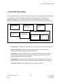
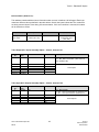
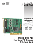
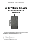
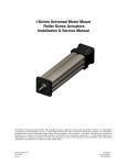
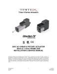
Tritex II EtherNet/IP - Option Tritex II Ethernet/IP Option.doc REV B 10/15/13 Exlar Corporation 952-368-3434 Tritex II - EtherNet/IP Option Tritex II EtherNet/IP Option.doc REV B 2 10/15/13 Exlar Corporation 952-500-6200 Tritex II - EtherNet/IP Option Contents 1. General .................................................................................................................................................. 5 1.1. IP Address ..................................................................................................................................... 6 1.2. Network Classes ........................................................................................................................... 6 1.3. Subnets ......................................................................................................................................... 7 1.4. Subnet Mask ................................................................................................................................. 8 1.5. Gateway ........................................................................................................................................ 8 2. EDS File ................................................................................................................................................. 8 3. BOOTP .................................................................................................................................................. 9 4. 3.1. IP Address Configuration .............................................................................................................. 9 3.2. Setting up your PC or Laptop to run the BOOTP server. ............................................................ 10 3.3. Configuring the Rockwell BOOTP/DHCP Sever Utility ............................................................... 10 3.4. Change Network Settings ........................................................................................................... 11 3.5. Disabling BOOTP ........................................................................................................................ 14 3.6. Force IP Renew Feature ............................................................................................................. 15 Configuring EtherNet/IP Messaging .................................................................................................... 16 4.1. 5. 4.1.1. Inputs ................................................................................................................................... 17 4.1.2. Outputs ................................................................................................................................ 18 4.1.3. Configuration ....................................................................................................................... 18 4.2. I/O Configuration Example .......................................................................................................... 19 4.3. Explicit Configuration Example ................................................................................................... 22 4.3.1. Example Get Attribute Single .................................................................................................. 22 4.3.2. Example Set Attribute Single .................................................................................................. 26 Tritex Expert Software ......................................................................................................................... 28 5.1. PC Communication ..................................................................................................................... 28 5.2. IP Parameters and Status ........................................................................................................... 28 5.2.1. IP Parameters ......................................................................................................................... 29 5.2.1.1. Active Parameters ................................................................................................................... 29 5.2.1.2. Set Parameters ....................................................................................................................... 29 5.2.2. Ethernet Interface Status Indicators ........................................................................................ 30 5.3. 6. Input/output Registers ................................................................................................................. 16 Tritex Data Mapping to I/O registers ........................................................................................... 31 Troubleshooting EtherNet/IP ............................................................................................................... 36 Tritex II EtherNet/IP Option.doc REV B 3 10/15/13 Exlar Corporation 952-500-6200 Tritex II - EtherNet/IP Option 6.1. BOOTP ........................................................................................................................................ 36 6.2. Ethernet Connection ................................................................................................................... 36 6.2.1. Ping ......................................................................................................................................... 36 6.3. Ethernet Diagnostic ..................................................................................................................... 38 6.4. Explicit Message Communications Errors .................................................................................. 39 6.5. PLC Input status word ................................................................................................................. 39 6.5.1. 7. Extended Status Information (Class 100, Instance 1, Attribute 101) .................................. 40 EtherNet/IP Object Model .................................................................................................................... 41 7.1. Objects and Attributes ................................................................................................................. 42 Tritex II EtherNet/IP Option.doc REV B 4 10/15/13 Exlar Corporation 952-500-6200 Tritex II - EtherNet/IP Option The following information describes the operation of EtherNet/IP as it relates to Tritex II with EtherNet/IP interface. The Tritex II EtherNet/IP option board supports the following features: 1. Device IP Address assignment through BOOTP or through Tritex Expert Software Drive commissioning through std RS485 communication to Tritex Expert Software EtherNet/IP device capable of Implicit I/O Messaging Up to 100 input registers(INT16) and 100 output registers(INT16) are available to be user Mapped to Tritex (Server) parameters through the Tritex Expert Software Full functional control of Tritex parameters General EtherNet/IP (Ethernet Industrial Protocol) is traditional Ethernet combined with an industrial application layer protocol targeted to industrial automation. This application layer protocol is the Control and Information Protocol (CIP™) CIP™, as a major network independent standard, is already used with ControlNet and DeviceNet. Therefore, converting from one of these protocols to EtherNet/IP is easy to do. Data exchange takes place with the help of an object model. In this way, ControlNet, DeviceNet and EtherNet/IP have the same application protocol and can therefore jointly use device profiles and object libraries. These objects enable plug-and-play interoperability between complex devices of different manufacturers. Tritex II EtherNet/IP Option.doc REV B 5 10/15/13 Exlar Corporation 952-500-6200 Tritex II - EtherNet/IP Option Figure 1 – ISO/OSI reference Model EtherNet/IP uses TCP/IP, UDP/IP, and Ethernet to carry the data of the CIP™ message structure between devices. That is, EtherNet/IP combines a physical network (Ethernet), with a networking standard (TCP/IP & UDP/IP), and a standard method of representing data (CIP™). 1.1. IP Address An IP address is a 32-bit number that uniquely identifies a host (computer or other device, such as a printer or I/O block) on a TCP/IP network. It is divided into four octets (8-bit sections), each octet being in the range 0...255. Each octet is separated by a decimal point and this type of format is commonly called 'dotted decimal notation' (e.g. 201.103.61.121 ). An IP address consists of two parts, one identifying the network and one identifying the node, or host. The Class of the address determines which part belongs to the network address and which part belongs to the node address. All nodes on a given network share the same network prefix but must have a unique host number. 1.2. Network Classes These IP addresses are divided into classes. The most common and support by the Tritex are classes A, B, and C. Classes D and E exist, but are not generally used by end users. Each of the address classes has a different default subnet mask. You can identify the class of an IP address by looking at its first octet. Class Address Range 001.000.000.000 to A 126.255.255.255 128.000.000.000 to B 191.255.255.255 192.000.000.000 to C 223.255.255.255 224.000.000.000 to D 239.255.255.255 240.000.000.000 to E 254.255.255.254 Figure 2 – Network Classes Table Tritex II EtherNet/IP Option.doc REV B Default Subnet Mask 255.000.000.000 255.255.000.000 255.255.255.000 6 10/15/13 Exlar Corporation 952-500-6200 Tritex II - EtherNet/IP Option Class A - This class is an IP Addresses has a value in the range 1...126 as the first octet. The values 0 and 127 are not available because they have special uses. Class A addresses use the first octet to identify the network which means that 126 addresses are usable, each of which can support 16,777,216 computers (hosts). An example of a Class A IP address is 102.168.212.226, where "102" identifies the network and "168.212.226" identifies the host on that network. Class B - This class is an IP Addresses has a value in the range 128...191 as the first octet. Class B addresses uses the first two octets to identify the network which means that 16,320 addresses are usable, each of which can support 65,536 computers (hosts). An example of a Class B IP Address 168.212.226.204 where "168.212" identifies the network and "226.204" identifies the host on that network. Class C - Intended for networks that would have a small number of computers (hosts) attached. Class C IP Addresses have a value in the range 192...223 as the first octet. Class C addresses use the first three octets to identify the network which means that 2,080,800 addresses (networks) are possible, each of which can support 254 computers (hosts). An example of a Class C IP address is 200.168.212.226 where "200.168.212" identifies the network and "226" identifies the host on that network. Class D - This is a class meant for multicasting only, for sending multicast messages to other groups of host machines. Class E - This is a class meant for experimental purpose only. Loopback- Addresses 127.0.0.0 to 127.255.255.255 are reserved for loopback, for internal testing on a local machine. 127.0.0.1 typically refers to your own local machine, you can test this - you should always be able to ping 127.0.0.1, irrespective of connectivity to the network, as it represents your own machine. IP addresses in this range are never valid Internet addresses. 1.3. Subnets To allow routing within large networks a convention was introduced in the specification RFC 950. Part of the Internet address, the subscriber ID is divided up again into a subnetwork number and the station number of the node. With the aid of the network number it is possible to branch into internal subnetworks within the partial network, but the entire network is physically connected together. The size and position of the subnetwork ID are not defined; however, the size is dependent upon the number of subnets to be addressed and the number of subscribers per subnet. Tritex II EtherNet/IP Option.doc REV B 7 10/15/13 Exlar Corporation 952-500-6200 Tritex II - EtherNet/IP Option 1.4. Subnet Mask A subnet Mask is a 32-bit mask used to divide an IP address into subnets and specify the networks available hosts. In a subnet Mask, two bits are always automatically assigned. For example, in 255.255.225.0, "0" is the assigned network address; and in 255.255.255.255, "255" is the assigned broadcast address. The 0 and 255 are always assigned and cannot be used. 1.5. Gateway A Gateway is a device which is used to forward IP packets to a remote destination. Another name for a Gateway is a Router. The definition of "remote" is a device that is not directly attached to the same network segment as the sending device. Because the source device can't send the IP packet directly to the destination device, it must ask another device on the network to help. The device that helps it send to remote destinations is the gateway, attached to multiple networks. The gateway, when it receives the packet to relay, determines the next closest hop on the path towards the ultimate destination, and relays the IP packet to that next hop. This next hop could either be the ultimate destination for the IP packet, or it could be another gateway closer towards the destination. This hop-by-hop process continues until the IP packet reaches its ultimate destination. 2. EDS File An EDS (Electronic Data Sheet) file is simply a text file used by network configuration tools to identify products and commission them on a network. For example, an EDS file describes Tritex device type, product revision, and its configurable parameters on a network. The Tritex EDS file can be downloaded from Exlar Corporation website (www.exlar.com). Tritex II EtherNet/IP Option.doc REV B 8 10/15/13 Exlar Corporation 952-500-6200 Tritex II - EtherNet/IP Option 3. BOOTP The following described the use of Exlar Expert Software and Rockwell BOOTP/DHCP Server Utility to configure the Tritex for an EtherNet/IP network. It is typically found in the Rockwell Software directory. The BOOTP server allows configuration and control of how nodes obtain an IP address. BOOTP servers come in several variations. Some are programs that are run on a PC or server, and some are integrated into routers and network infrastructure equipment. These instructions use Rockwell’s BOOTP Server (version 2.3); a stand-alone program that incorporates the functionality of standard BOOTP. If BOOTP is enabled and the BOOTP request fails (time-out occurs after approximately 30 seconds), then the Tritex will come online at the IP address that resides in non-volatile memory. This will be the value assigned by the previous BOOTP request or the factory default of 192.168.0.254. If BOOTP has been disabled and the power is cycled, the IP address that resides in non-volatile memory will be used. NOTE! 3.1. Default configuration is BOOTP disabled - Ethernet address (IP, subnet and gateway) is configured using Tritex Expert software. IP Address Configuration The IP address can be configured by using the following methods: BOOTP Tritex Expert Software Tritex II EtherNet/IP Option.doc REV B 9 10/15/13 Exlar Corporation 952-500-6200 Tritex II - EtherNet/IP Option 3.2. Setting up your PC or Laptop to run the BOOTP server. First confirm that the Ethernet Adapter is configured correctly, for the local network. In the examples we are using a standard Class C TCP/IP network with the address’s of 192.168.0.XXX. The PC is configured for address 192.168.0.21, Subnet Mask 255.255.255.0 and leave Default Gateway blank 3.3. Configuring the Rockwell BOOTP/DHCP Sever Utility The Rockwell BOOTP/DHCP Server Utility allows: assign IP addresses, subnets, and other parameters to BOOTP and/or DHCP clients configure client devices to enable or disable BOOTP/DHCP modify the IP addresses of EtherNet/IP devices with known MAC addresses, but unknown IP addresses After the PC Setup is complete, run the BOOTP/DHCP server utility and the following main screen will be displayed: Figure 3 – BOOTP/DHCP Server Utility Tritex II EtherNet/IP Option.doc REV B 10 10/15/13 Exlar Corporation 952-500-6200 Tritex II - EtherNet/IP Option Next, under the Tools menu, please click on the Network Settings menu item and configure the contents of the “Subnet Mask” and “Gateway” as defined in Figure 4. Click the OK button to accept the settings and close the Network Settings configuration. Figure 4 – Network Settings 3.4. Change Network Settings Use the BOOTP to dynamic configuration the Tritex IP address or Subnet Mask via a BOOTP server. NOTE! BOOTP must be enable (Factory default is Bootp Disable) Click on Tools in toolbar and select Network Settings. Verify that the Subnet Mask and the Gateway Address match those of your network. If necessary, change the values to match your network. Please refer to Figure 5. Click the OK button to accept the settings and then Cycle power to actuator. Figure 5 – Change Network Settings Tritex II EtherNet/IP Option.doc REV B 11 10/15/13 Exlar Corporation 952-500-6200 Tritex II - EtherNet/IP Option In the BOOTP Request History panel the Ethernet Addresses (MAC) of the devices issuing BOOTP request is displayed. Please refer to Figure 6 Figure 6 – BOOTP Request History Panel NOTE! Tritex II EtherNet/IP Option.doc REV B The Tritex MAC Address is found near Ethernet connector 12 10/15/13 Exlar Corporation 952-500-6200 Tritex II - EtherNet/IP Option Double-click on the hardware address of the device to configure. The New Entry pop-up window with the device’s Ethernet Address (MAC). Please refer to Figure 7 Figure 7 – Assign IP Address Enter the new IP Address, and click on OK. The device will be added to the Relation List, displaying the Ethernet Address (MAC) and corresponding IP Address. The Status will be updated showing the address beginning assign to the Ethernet Address. Please refer to Figure 8. Figure 8 – Assign Parameters Command Successful Tritex II EtherNet/IP Option.doc REV B 13 10/15/13 Exlar Corporation 952-500-6200 Tritex II - EtherNet/IP Option 3.5. Disabling BOOTP To permanently assign IP parameters or allow the Tritex Expert Software to change Parameters BOOTP needs to be disabled. To disable BOOTP, run the BOOTP/DHCP Server Utility, then cycle power to the Tritex. Add the hardware address of the Tritex to the Relation List by using the procedures outline in “Change Network Setting “ Highlight the Tritex in the lower “Relation List” section of the screen and then click on the Disable BOOTP/DHCP button. Please refer to Figure 9. Confirm the operation completed successfully by recycling the power to the Tritex, after the Status message in the lower left corner of the application indicates, “[Disable BOOTP] Command Successful”. Please refer to Figure 9. Figure 9 – Disable BOOTP Command Successful Tritex II EtherNet/IP Option.doc REV B 14 10/15/13 Exlar Corporation 952-500-6200 Tritex II - EtherNet/IP Option 3.6. Force IP Renew Feature The Force IP Renew feature can be used to reconfigure the Tritex with BOOTP disabled. This can be useful: If you do not know the IP address of a configured device If you know the IP address but want to change the configuration. To use this feature, perform the following steps: 1) Connect the Tritex to your network and run the BOOTP Service Utility. 2) In the Relation List Click on the New button. The New Entry pop-up window will open. Please refer to Figure 10. 3) Enter the fixed Ethernet Address (MAC) of the Tritex 4) Enter the IP Address, Subnet Mask, and Gateway you want to assign to the device, and click on OK. The device will appear in the Relation List. 5) Select the device from the Relation List follow by clicking Enabling BOOTP button. Please refer to Figure 11. 6) Then cycle power to the Tritex. The Tritex will issue a BOOTP request. The BOOTP utility will respond by assigning it the configuration you just specified. Figure 10 – New Entry Figure 11 – Enable BOOTP Command Successful Tritex II EtherNet/IP Option.doc REV B 15 10/15/13 Exlar Corporation 952-500-6200 Tritex II - EtherNet/IP Option 4. Configuring EtherNet/IP Messaging Note: The convention in this section of the manual is from the PLC (Client) perspective. As such, an assembly is called an “Output Assembly-Instance” when outputted from the PLC and received by the Tritex (Server). An “Input Assembly-Instance” is outputted from the Tritex and read by the PLC. The Tritex EtherNet/IP Input and Output connection can be divided into I/O connections (implicit), and explicit messaging connection. Implicit Messages - are exchanged across I/O Connections with an associated Connection ID. The Connection ID defines the meaning of the data and establishes the regular/repeated transport rate and the transport class. No messaging protocol is contained within the message data as with Explicit Messaging. Implicit Messages can be point to point (unicast) or multicast and are used to transmit application specific I/O data. Explicit Messages- can be sent as a connected or unconnected message. CIP defines an Explicit Messaging protocol that states the meaning of the message. This messaging protocol is contained in the message data. Explicit Messaging provide the means by which typical request/response oriented functions are performed. These messages are typically point-to-point. Message rates and latency requirements are typically not as demanding as I/O messaging. 4.1. Input/output Registers The Tritex has a set number of 101 input and/or 101 output 16 bit registers that are transferred with each update. These registers are mapped to specific parameter definition in the Tritex Expert Software. Unmapped registers will carry data across with the messages, but will not be associated to affect any functionality of the Tritex. Outputs are sent from the Tritex consistently while the Inputs only updates when a value is changed. Tritex II EtherNet/IP Option.doc REV B 16 10/15/13 Exlar Corporation 952-500-6200 Tritex II - EtherNet/IP Option 4.1.1. Inputs The first word of the PLC input provides the status of the Tritex communication. It provides information about the status of the configuration, health of the Tritex option board. PLC Inputs (Tritex Outputs) Instance Word Bit 15 – Bit 8 Bit 7 Bit 6 Bit 5 Bit 4 Bit 3 Bit 2 Bit 1 Bit 0 Input Status Word 0 1 101 ... ... 100 Figure 12 – PLC Input Map Bit (0 = LSB) Status Flag 0 Error – Tritex is responding with error codes. Extended Module Status (Attribute 101) contains additional error information. 1 Error – communication with Tritex timed-out (was previously established) 2 Error – communication with Tritex cannot be established at all 3-7 Reserved 8 Unit is currently active at factory defaults 9 Unit has a new configuration that will take effect upon reset. 10-15 Reserved Figure 13 – Input Status Word NOTE! Tritex II EtherNet/IP Option.doc REV B If error is active - Expert Software will display Minor fault condition on the EtherNet/IP page. Refer to Module Status Indicators for more information. 17 10/15/13 Exlar Corporation 952-500-6200 Tritex II - EtherNet/IP Option 4.1.2. Outputs Bit 0 of the first word is defined as the Run/Idle command for the Tritex Port 2. When an I/O connection is active, a zero (0) in this bit represents Idle Mode and a one (1) represents Run Mode. In Idle mode, the Tritex will only update PLC Inputs (Tritex Output) information. When Run/Idle is active (1) both the PLC and Tritex Expert Software have the capability of writing the same command to Tritex; disabling Run/Idle (0) could be use to insure command source. Outputs PLC (Tritex Inputs) Word Instance Bit 15 – Bit 8 Bit 7 Bit 6 Bit 5 Bit 4 Bit 3 Bit 1 Bit 0 Run/Idle 0 1 102 ... ... 100 Figure 14 – PLC Outputs Name Run/Idle Bit 2 Description Enable Output Update 0 : Idle - Tritex Output List are not updated 1: Run - Tritex Output List are updated Figure 15 – Output Command Bit 4.1.3. Configuration Configuration data is not supported by the Tritex; the Configuration Assembly and a size is 0. Configuration Instance 128 data size of 0 registers Figure 16 – PLC Configuration Tritex II EtherNet/IP Option.doc REV B 18 10/15/13 Exlar Corporation 952-500-6200 Tritex II - EtherNet/IP Option 4.2. I/O Configuration Example The following example describes the process used to configuring I/O system with RSLogix 5000™ and Tritex with EtherNet/IP. 1. Run RSLogix 5000™ software and configure the PLC for the correct processor, rack and slot configurations. 2. Right click on the Ethernet folder located under I/O Configuration and left click to add a new module to this folder. Figure 17 – Adding a New module using PLCs Software 3. Choose the Allen-Bradley –Generic Ethernet-Module. After selecting a name for the device, click OK. Figure 18 – Choose EtherNet/IP Module type Tritex II EtherNet/IP Option.doc REV B 19 10/15/13 Exlar Corporation 952-500-6200 Tritex II - EtherNet/IP Option 4. Configure New Module Connection Properties, IP Address and Comm Format. Assign name to new Module (Tritex) and then select OK. Figure 19 – Specify address and Connection Parameters 5. Connection Figure 20 – Configuring New Module Connection Request Packet Interval (RPI): This field specifies the Requested Packet Interval (RPI), which defines the amount if time (in milliseconds) between the data exchanges across an implicit messaging connection. NOTE! Tritex II EtherNet/IP Option.doc REV B RPI > 20 Recommended 20 10/15/13 Exlar Corporation 952-500-6200 Tritex II - EtherNet/IP Option Inhibit Module: Checking this box prevents the PLC from attempting to establish a connection with the Tritex. Refer to RSLogix for additional information on this function. Major Fault On Controller If Connection Fails While in Run Mode: This option will cause the controller to generate a major fault when the connection fails. Use Unicast Connection over EtherNet/IP: Select between Unicast and Multicast for EtherNet/IP connection base on system needs. NOTE! Multicast I/O connections can greatly impact the performance of an Ethernet network since—unlike unicast packets, which are sent directly to a single device—multicast packets are sent to all devices on the network by default. This increases the load on every device, including the switches, and each individual network segment 6. Verify configuration Figure 21 – Example Project tree – Added Tritex By highlight the “Controller tags” in the project tree, it is possible to view the newly added Tritex. See Figure 22 for a display of the controller tags. Figure 22 – Example Controller tags for Tritex NOTE! Tritex II EtherNet/IP Option.doc REV B For the above example. To update Tritex Outputs – TritexO.Data[0].0 must be turn ON. 21 10/15/13 Exlar Corporation 952-500-6200 Tritex II - EtherNet/IP Option 4.3. Explicit Configuration Example Explicit Messaging is used to transfer data that does not require continuous updates. With explicit messaging, you can configure and monitor Tritex parameters on the EtherNet/IP network. The RSLogix™ software can be configured to send an EtherNet/IP message to the Tritex by using the Message (MSG) Instruction. Get Attribute Single (Read) Set Attribute Single (Write) 4.3.1. Example Get Attribute Single The following ladder diagram demonstrates the ladder instructions needed to send explicit message from CompactLogix L23E Ethernet to the Tritex Inputs. Figure 23 – Ladder Diagram Get 1. Add Message Instruction to RSLogix5000™ ladder Diagram. Please see figure 23. NOTE! To display the Message Configuration dialog box in RSLogix5000, add a message instruction (MSG), create a new tag for the message (properties: Base tag type, MESSAGE data type, controller scope), and click the blue box inside the message. 2. Create new tag for the MSG (Message) Instruction. Tritex II EtherNet/IP Option.doc REV B 22 10/15/13 Exlar Corporation 952-500-6200 Tritex II - EtherNet/IP Option Figure 24 – Get Message New Tag Figure 25 – Get Massage Configuration Properties 3. In new Tag menu, assign name to tag, Check Open MESSAGE Configuration box, then click OK. See Figure 24. 4. Configure Message Configuration parameters. See figure 25. Configuration Message Type Service Type Service Code Class Instance Attribute Destination Value CIP Generic Get Attribute Single e (Hex) 4 (Hex) 101 (Dec) 3 (Hex) Tritex_InputData Description Message Format Read parameter data Get_Attribute_Single Assembly Object Assembly Input Object Instance Parameter Value Controller Tag for response data Figure 26 – Tritex_ReadInputs 5. In the Message Configuration section for Message click on the Communications Tab, this tab will allow the setting of the target device to get the explicit message. See Figure 27. Tritex II EtherNet/IP Option.doc REV B 23 10/15/13 Exlar Corporation 952-500-6200 Tritex II - EtherNet/IP Option 5.1 Click and open Message Path Browser and select local Ethernet module in PLC. 5.2 Configure Path Description LocalENB 2 192.168.0.254 Local communication module EtherNet/IP port # Tritex address Figure 27 – Get Communication Properties Path - shows the route that the message takes to get to the destination. It is a combination of the Ethernet Card, location in the PLC and the module address. Refer to your PLC user manual for more information on configuring Path. Timed Out option – Time out for an unconnected message or for making a connection. 6. After configuring Path, Return to Configuration Tab. 7. From Configuration Parameters Menu, click New Tag and define Destination Tag for Input data. Figure 29 –Destination size Figure 28 –Destination Tag 8. From Tag Menu select icon next to Data Type and change INT Dim 0 to “101”, then click OK, returning to New Tag Menu. Click OK to Defined New Destination Tag “Tritex_InputData” See Figure 28 and 29. Tritex II EtherNet/IP Option.doc REV B 24 10/15/13 Exlar Corporation 952-500-6200 Tritex II - EtherNet/IP Option Figure 30 – Get Massage Configuration Properties 9. From the Message Configuration Menu select Destination Tag name “Tritex_InputData”. Click Apply button to configure Message Instruction Figure 31 – MSG Read Tritex Inputs NOTE! Refer to Allen-Bradley Logix5000 Controllers General Instruction Manual for additional information on Message (MSG) Instruction and Application Configuration Details. XIC instruction is used to trigger Explicit Message read Tritex II EtherNet/IP Option.doc REV B 25 10/15/13 Exlar Corporation 952-500-6200 Tritex II - EtherNet/IP Option 4.3.2. Example Set Attribute Single The following ladder diagram demonstrates the ladder instructions needed to send explicit message from CompactLogix™ L23E Ethernet to the Tritex Outputs. 1. Add Message Instruction to RSLogix5000™ ladder Diagram. Please see figure 23. 2. Create new tag for the MSG (Message) Instruction. 3. In new Tag menu, assign name to tag, Check Open MESSAGE Configuration box, then click OK. See figure 32. 4. Configure Message Configuration parameters. See figure 33 and 34. Figure 32 – Set – Message Tag Figure 33 – Set Message Configuration Properties Configuration Message Type Service Type Service Code Class Instance Attribute Source Element Source Length Value CIP Generic Set Attribute Single 10 (Hex) 4 (Hex) 102 (Dec) 3 (Hex) Tritex_OutputData 202 Bytes Description Message Format Write parameter data Set_Attribute_Single Assembly Object Assembly Output Object Instance Parameter Value Controller Tag for response data 101 16-bit words of data is sent to Tritex Figure 34 – Tritex_WriteOutputs Tritex II EtherNet/IP Option.doc REV B 26 10/15/13 Exlar Corporation 952-500-6200 Tritex II - EtherNet/IP Option 5. In the Message Configuration section for Message click on the Communications Tab, this tab will allow the setting of the target device to get the explicit message. See Figure 27. 6. After configuring Path, Return to Configuration Tab. 7. From Configuration Parameters Menu, click New Tag and define Source Tag for Output data. Figure 36 – Set Source Element size Figure 35 – Set Source Element Tag 8. From Tag Menu select icon next to Data Type and change INT Dim 0 to “101”, then click OK, returning to New Tag Menu. Click OK to Defined New Source Element Tag “Tritex_OutputData” See Figure 32 and 33. Figure 37 – MSG Write Tritex Outputs NOTE! Refer to Allen-Bradley Logix5000 Controllers General Instruction Manual for additional information on Message (MSG) Instruction and Application Configuration Details. XIC instruction is used to trigger Explicit Message write Tritex II EtherNet/IP Option.doc REV B 27 10/15/13 Exlar Corporation 952-500-6200 Tritex II - EtherNet/IP Option 5. Tritex Expert Software 5.1. PC Communication When using the Expert software, an RS485 converter will be required to interface between one of the PC communication ports and the RS-485. Please refer to the Tritex Installation guide for more information. 5.2. IP Parameters and Status Figure 38 – Offline view of the Active IP parameters and Address Setup fields Using the Tritex Expert software, you will see the above values populate the Active IP parameters. Here the Ethernet MAC-ID, IP Address, Subnet Mask and Default Gateway are displayed. The data enter fields to the right are used to configure the IP Address, Subnet Mask and Default Gateway. NOTE! Tritex II EtherNet/IP Option.doc REV B MAC–ID is a unique identifier assigned to each Tritex 28 10/15/13 Exlar Corporation 952-500-6200 Tritex II - EtherNet/IP Option 5.2.1. IP Parameters 5.2.1.1. Active Parameters Display Tritex active IP parameters Figure 39 – Active Parameters IP Address Subnet Mask Default Gateway 192.168.000.254 255.255.255.000 000.000.000.000 Figure 40 – Default IP Parameters 5.2.1.2. Set Parameters To set the IP Address, Subnet Mask or Gateway modify the fields to your specific needs and select Save Addresses to Drive. These changes will not take effect until the power to the Tritex is cycled. Upon power up the new IP Address will be assigned and will show up in the Active MAC-ID parameter container. Figure 41 – Set Parameters Tritex II EtherNet/IP Option.doc REV B 29 10/15/13 Exlar Corporation 952-500-6200 Tritex II - EtherNet/IP Option IP Address Subnet Mask Class A: 001.000.000.000 to 126.255.255.255 Class B: 128.000.000.000 to 191.255.255.255 Class C: 192.000.000.000 to 223.255.255.255 255.000.000.000 to 255.255.255.000 Figure 42 – IP Parameters Limits NOTE! BOOTP must be disabled to utilize the IP address setting through the Tritex Expert Software 5.2.2. Ethernet Interface Status Indicators Status indicators, help maintenance personnel to quickly identify the status of the Network connection and interface module. Two types of status indicators are provided: • Network status indicator • Module status indicator Figure 43 –Ethernet Status Indicators Indicator State Steady Off Steady Green Flashing Green Flashing Red Steady Red State No Powered / No IP Connected No I/O Connection Connection timeout Duplicate IP Network Description The device is powered off or is powered on but with no IP address configured At least one CIP connection is established An IP address is configured, but no CIP connection is established The established CIP connection has timeout Duplicate IP address detection, the interface module has detected that its IP address is already in use. Figure 44 -Network Status Indicators Indicator State Steady Off State No power (Ethernet) Module Description The interface module has no power supplied to it Steady Green Operational The interface module is operating correctly Flashing Green Standby The interface module has not been configured Flashing Red Minor fault Steady Red Flashing Green/Red Major Fault Self-Test Recoverable error is active; the error information will be loaded in the first word of the PLC input status word. Fault will clear on the next valid message The interface module has detected a non-recoverable major fault. The interface module is performing power-up testing Figure 45 - Module Status Indicators Tritex II EtherNet/IP Option.doc REV B 30 10/15/13 Exlar Corporation 952-500-6200 Tritex II - EtherNet/IP Option 5.3. Tritex Data Mapping to I/O registers All Tritex functionality is parameter based. This means we have a listing of parameters associated with every functional capability of the Tritex. When setting up the EtherNet/IP mapping to the 101 Inputs and 101 Outputs, first a list of the parameters must be defined and determined whether they are Read Parameters from the EtherNet/IP Host or Write Parameters to the Host. Once this list is created, mapping the parameters to the Translation Table of registers is done as shown in Figure x.2. The Output Mapping tab is used to map the parameters that are Output by the Tritex and Read into the Host. The Input Mapping tab is used to map the parameters that are Inputs to the Tritex and Written from the Host. The Input Mapping and Output Mapping tabs work in the same manner. Figure 46– Selecting parameters to be mapped to the Translation Table. After step #2 above information about the parameter is displayed. 32 bit or double word parameters can only be assigned to tables starting with odd numbers. If a 32 bit parameter is selected and even table number is selected the “Add” button will be gray. If only half of a 32 bit parameter is needed, for example, all velocities are 32 bit parameters their data format is 8.24 revs/sec, rarely would 24 bits of precision be needed to the right of the decimal point from a user perspective. In this case one could select only the high word of the parameter by un-checking the Low box resulting in a 16 bit velocity parameter in the format of 8.8 revs/sec , 8 bits on each side of the decimal point. Assigning the parameters to be transferred between the Tritex and PLC is breeze; the hard part is understanding the Tritex parameters and their format so they can be controlled from the PLC. The Tritex II Parameters manual describe the function of every parameter, in some cases the interaction with other Tritex II EtherNet/IP Option.doc REV B 31 10/15/13 Exlar Corporation 952-500-6200 Tritex II - EtherNet/IP Option parameters and most importantly the format of data for each parameter. Parameters such as Move Distances and Velocity are straight forward however many of the parameters used for control are 16 bit registers represented by bit maps or Enumeration tables, the common bit maps are covered in Appendix A of the Parameter Manual. To assist with validating the data sent/received, the Input/Output Monitor tabs allow the user to view the non-scaled decimal value of the 16 bit register. This value will match the value observed from the Host. See figure 47 to identify its use. The Input Monitor and Output Monitor tabs both operate in the same manner. Figure 47– Monitoring parameters to validate data sent/received by the host. Tritex II EtherNet/IP Option.doc REV B 32 10/15/13 Exlar Corporation 952-500-6200 Tritex II - EtherNet/IP Option Example 1: Writing Move 0 Position from the PLC to the Tritex Figure 48 – Example 1 1. 2. 3. 4. Select the Input Mapping tab (Input to the Tritex from the PLC) Select Move0, Primary, Position Click Apply, information about the parameter is displayed Since this is 32 bit parameter select and Odd number in the Translation table and Click the Add button 5. After a download the Tritex is now ready to receive this data from the place and write it directly to the Move0 position register 6. Determine what to write from the PLC. Click on the Help button and pdf file will open explaining the Move parameter details. Move Position has a variable type of POS 32, in the data table details the format is 16.16, (16 digits on each side of the decimal point), and the units are in Revs (motor revolutions). If the PLC writes a 2 to register 1 and 5 to register 2 and Move0 will have a move command of 5.200 Revs. Tritex II EtherNet/IP Option.doc REV B 33 10/15/13 Exlar Corporation 952-500-6200 Tritex II - EtherNet/IP Option Example 2: Enabling the Tritex from a PLC Figure 49 – Example 2 1. Select the Input Mapping tab (Input to the Tritex from the PLC) 2. Enable bit is found in the Mode sub group of Control/ Input Functions. Click the help button for details on the Input Function Events bit map. 3. Select Control, Mode and Click Apply 4. Select the desired register number from the translation table. Since it is a 16 bit parameter either an odd or even number can be selected. 5. From the information in found in the Help pdf, the bit map of the Mode word is shown as: IEG_MODE RESET BKOV TSEL TENA H2 H1 15 14 13 12 11 10 ALT 9 8 7 6 5 4 3 2 EL EE 1 0 As described bit 1, EL is Enable Maintained 6. After a download, writing a 1 or a 0 to bit 1 of word 3 from the PLC will control the Tritex Enable. Tritex II EtherNet/IP Option.doc REV B 34 10/15/13 Exlar Corporation 952-500-6200 Tritex II - EtherNet/IP Option Below figure shows the relationship of Tritex Input Translation Table to RSLogix Output controller tags. Tritex Expert Software RSLogix (I/O Connection) Inputs Outputs Figure 50 - Tritex Input vs. RSLogix Output Tags Tritex II EtherNet/IP Option.doc REV B 35 10/15/13 Exlar Corporation 952-500-6200 Tritex II - EtherNet/IP Option 6. Troubleshooting EtherNet/IP Exlar Tritex II option board with EtherNet/IP is an intelligent interface between EtherNet/IP and Tritex registers. Communication fault information is available from the EtherNet/IP and Exlar Expert Software. 6.1. BOOTP The following are usefully steps in troubleshooting BOOTP: • • Verify Subnet Mask Verify BOOTP is enabled. The BOOTP procedure in this manual will work as written if both the PC (Client) and the Tritex (Server) are on the same subnet. For example: Computer’s IP address = 192.168.000.020 Tritex IP address = 192.168.000.254 Subnet Mask of both = 255.255.255.000 However, if the computer’s IP address is initially 192.168.1.2, it will not be possible to change the IP address because clicking on Enable BOOTP in the Relation List will fail. To correct this problem, change the IP address of your PC so that the PC and the Tritex are on the same subnet. 6.2. Ethernet Connection 6.2.1. Ping 1. To test the communication with the Tritex and the correct assignment of the IP address call up the DOS prompt under Start menu / Program / MSDOS Prompt. 2. Enter the command: "ping" with the IP address you have assigned in the following form: ping [space] XXXX . XXXX. XXXX. XXXX (=IP address). Example: ping 192.168.0.254 Tritex II EtherNet/IP Option.doc REV B 36 10/15/13 Exlar Corporation 952-500-6200 Tritex II - EtherNet/IP Option Figure 51 – Example Testing Tritex Ethernet Connection 3. When the Return key has been pressed, your PC will receive a response from the Tritex, which will then be displayed in the DOS prompt. If the error message: "Timeout" appears instead, please compare your entries again to the allocated IP address. 4. When the test has been performed successfully, you can close the DOS prompt. The network node has now been prepared for communication. Tritex II EtherNet/IP Option.doc REV B 37 10/15/13 Exlar Corporation 952-500-6200 Tritex II - EtherNet/IP Option 6.3. Ethernet Diagnostic The Exlar Expert software Diagnostic page offers additional information to diagnose communication problems. Ethernet diagnostic wedge indicate communication status between Ethernet, piggyback and main controller board. Figure 52 – Diagnostic Comms Channel - Ethernet Faulted: Channel B (Ethernet) communication fault has occurred. If communication fault option is enabled and associated Ethernet fault is active, this fault condition is set. (Reference Expert Software manual on more information on enabling/disabling faults) Command Idle: If a valid Modbus command from the Ethernet interface has not been received in the Communication Idle timed programmed, this fault condition will be set. Protocol: If a Modbus protocol error, such as incorrect parity, invalid CRC, framing error etc. occurs, this fault condition will be set Data Error: If a Modbus data error, such as invalid address, invalid range etc. occurs, this fault condition will be set. Module: If the Ethernet/IP module status is not OPERATIONAL or SELF-TEST (see figured 45) this fault condition will be set. Flag does not auto clear; a Reset Faults command is needed. Connection: If the Ethernet/IP network status is not CONNECTED (See figured 44), this fault condition will be set. Flag is cleared when CONNECTED becomes active. Tritex II EtherNet/IP Option.doc REV B 38 10/15/13 Exlar Corporation 952-500-6200 Tritex II - EtherNet/IP Option 6.4. Explicit Message Communications Errors When there is a problem with a request message sent from the master in explicit communications, the Tritex will return one of the following error codes. Error Code (hex) Description Cause Possible Solutions 08 09 Path destination unknown Service not supported Invalid attribute value 0E Attribute not settable Attempted to change a read-only attribute. 13 Not enough data 14 Attribute not supported The data size is incorrect. Attempted to execute a service not defined for the attribute. 16 Object does not exist An unsupported object was specified. 20 Invalid parameter Attempted to change to a data value outside the setting range. 05 The Object Class or instance is incorrect The service code is incorrect. The attribute is incorrect. Correct the Object class or Instance code. Correct the service code. Correct the attribute. Correct the service code or attribute setting. Correct the data size. Correct the service code or attribute setting. Correct the class or instance setting. Specify a data value within the setting range Figure 53 – Explicit Message Communications Errors 6.5. PLC Input status word The first Input word always maintains the current status of the Tritex according to the bit fields of flags in the table below. A flag is considered to be “Set” if the corresponding bit is 1. If the value of the status word is zero (0), then everything is currently operating normally with a valid configuration and no pending errors. Bit (0 = LSB) Status Flag 0 Error – Tritex is responding with error codes. Extended Module Status (Attribute 101) contains additional error information. 1 Error – communication with Tritex timed-out (was previously established) 2 Error – communication with Tritex cannot be established at all 3-7 Reserved 8 Unit is currently active at factory defaults 9 Unit has a new configuration that will take effect upon reset. 10-15 Reserved Figure 54 –Input Status word Tritex II EtherNet/IP Option.doc REV B 39 10/15/13 Exlar Corporation 952-500-6200 Tritex II - EtherNet/IP Option 6.5.1. Extended Status Information (Class 100, Instance 1, Attribute 101) This attribute contains additional error information when an error in Attribute 100 is flagged. Each byte contains a different value as defined in the table below. Overall, the bytes indicate the error codes that are being returned by the Tritex during I/O communication. If the error condition is removed, this status will be set back to zeroes. Byte 3 (MSB) Byte 2 Byte 1 Byte 0 (LSB) Exception Code from Tritex Error Code from Tritex (128 + FC) 001 Assembly Instance receiving the error (101, 102) Figure 55 – Extended Adapter Fault Information Exception Code from Tritex - Refer to Tritex Protocol Specification for more information. Assembly Instance receiving the error: 101 = Ethernet made request for Outputs (PLC Inputs) 102 = Ethernet made request for Inputs (PLC Outputs) Tritex II EtherNet/IP Option.doc REV B 40 10/15/13 Exlar Corporation 952-500-6200 Tritex II - EtherNet/IP Option 7. EtherNet/IP Object Model In the EtherNet/IP networks, Tritex act as server with support for both explicit and implicit I/O messaging. The Identity Object, Ethernet link Object, TCP/IP Object and Other Objects are required by the EtherNet/IP specification. The different instances of the Assembly Object are used to exchange application data with EtherNet/IP clients. The object model by Tritex is illustrated in the following figure: Identity Object (0x01) Ethernet Link Object (0xF6) Other Internal Objects Assembly Object (0x04) TCP/IP Object (0xF5) Configuration Object (0x64) Input (Instance 101) Output (Instance 102) Figure 56 – Object Model • Identity Object: this object provides identification of, and general information about, the device. • Ethernet Link Object: Ethernet link object maintains link-specific counters and status information for an Ethernet 802.3 communications interface. • TCP/IP Object: The TCP/IP Object provides a mechanism to query and possible configure a device’s TCP/IP network interface configuration. Examples of items include a device’s IP Address, Network Mask and Gateway Address • Assembly Object - The Configuration Assembly Object is not implemented. However, some EtherNet/IP clients require one. If this is the case, use Instance ID 0x80 with a data length of 0 • Configuration Object – Exlar Configuration and Tritex status information Tritex II EtherNet/IP Option.doc REV B 41 10/15/13 Exlar Corporation 952-500-6200 Tritex II - EtherNet/IP Option 7.1. Objects and Attributes This section described the attributes and services that can useful during troubleshooting. Configuration and status Object – Class 64 Hex, Instance 1 Attribute ID Access Rule Name Data Type Description 100 Get Status UINT (See below for Bit Mask definition) 101 Get Extended Status UDINT (See below for definition) Figure 57 – Configuration and Status Object Status (Attribute 100) This attribute always maintains the current status of the module according to the bit field of flags defined in the table below. A flag is considered to be “Set” if the corresponding bit is 1. If the value of the status attribute is zero (0), then everything is currently operating normally with a valid configuration and no pending edits. Bit (0 = LSB) Status Flag 0 Error – Tritex channel B is responding with error codes. Extended Module Status (Attribute 101) contains the error code information. 1 Error – communication with Tritex Channel B timed-out (was previously established) 2 Error – communication with Tritex Channel B cannot be established at all 3-7 Reserved 8 Unit is currently active at factory defaults 9 Unit has a new configuration that will take effect upon reset. 10-15 Reserved Figure 58 –Input Status word Tritex II EtherNet/IP Option.doc REV B 42 10/15/13 Exlar Corporation 952-500-6200 Tritex II - EtherNet/IP Option Extended Status (Attribute 101) This attribute contains additional error information when an error in Attribute 100 is flagged. Each byte contains a different value as defined in the table below. Overall, the bytes indicate the error codes that are being returned by the Tritex during I/O communication. If the error condition is removed, this status will be set back to zeroes. Byte 3 (MSB) Exception Code from Tritex Byte 2 Byte 1 Byte 0 (LSB) Error Code from Tritex (128 + FC) 001 Assembly Instance receiving the error (101, 102) Figure 59 – Extended Adapter Fault Information Tritex Output (PLC Input) Assembly Object – Class 4, Instance 101 Attribute ID 3 Access Rule Get Size Word 101 0 Description 16 – Bits Status information ( See Class 64 hex, Attribute 100) 1 ... ... 99 100 Tritex Inputs Figure 60 – Input Object Tritex Input (PLC Output) Assembly Object – Class 4, Instance 102 Attribute ID 3 Access Rule Get/Set Size Word Description 101 0 16 – Bits Run/Idle 0 = Idle – Tritex Input Parameter not updated by PLC 1 = Run – Tritex Input Parameter updated by PLC 1 ... ... 99 100 Tritex Outputs Figure 61 – Output Object Tritex II EtherNet/IP Option.doc REV B 43 10/15/13 Exlar Corporation 952-500-6200