1
C320 Turbo/PCI User’s Manual
Fourth Edition, July 2008
www.moxa.com/product
© 2008 Moxa Inc., all rights reserved.
Reproduction without permission is prohibited.
www.ipc2u.ru
www.moxa.pro
C320 Turbo/PCI User’s Manual
The software described in this manual is furnished under a license agreement and may be used only in accordance
with the terms of that agreement.
Copyright Notice
Copyright © 2008 Moxa Inc.
All rights reserved.
Reproduction without permission is prohibited.
Trademarks
MOXA is a registered trademark of Moxa Inc.
All other trademarks or registered marks in this manual belong to their respective manufacturers.
Disclaimer
Information in this document is subject to change without notice and does not represent a commitment on the part of
Moxa.
Moxa provides this document “as is,” without warranty of any kind, either expressed or implied, including, but not
limited to, its particular purpose. Moxa reserves the right to make improvements and/or changes to this manual, or to
the products and/or the programs described in this manual, at any time.
Information provided in this manual is intended to be accurate and reliable. However, Moxa assumes no
responsibility for its use, or for any infringements on the rights of third parties that may result from its use.
This product might include unintentional technical or typographical errors. Changes are periodically made to the
information herein to correct such errors, and these changes are incorporated into new editions of the publication.
Technical Support Contact Information
www.moxa.com/support
www.ipc2u.ru
Moxa Americas:
Toll-free: 1-888-669-2872
Tel: +1-714-528-6777
Fax: +1-714-528-6778
Moxa China (Shanghai office):
Toll-free: 800-820-5036
Tel: +86-21-5258-9955
Fax: +86-10-6872-3958
Moxa Europe:
Tel: +49-89-3 70 03 99-0
Fax: +49-89-3 70 03 99-99
Moxa Asia-Pacific:
Tel: +886-2-8919-1230
Fax: +886-2-8919-1231
www.moxa.pro
About This Manual
This manual is composed of six Chapters and one Appendix. This manual is written for installer, system
administrator and software programmer.
If you are a first-time installer and system administrator, we recommend you to go through the whole
manual except Chapter 4.
If you are a software programmer, you may refer to Chapter 4 “Serial Programming Tools”.
If you need cable wiring information, please see Chapter 5 “Connection Option (Opt8x) and Cable
Wiring”.
If you encounter any problem during installation, please refer to Chapter 6 “Troubleshooting”.
☞ In this manual, C320Turbo Series refers to C320Turbo and C320Turbo/PCI.
Chapter 1 Introduction
Overview and features for C320Turbo/PCI are described. Also check list and overall installation
guide.
Chapter 2 Hardware Installation
Hardware installation for C320Turbo/PCI .
Chapter 3 Software Installation
This Chapter details the software installation, configuration, driver loading/unloading, driver upgrade
and removal for various operating systems: Windows NT, Windows 95/98 and UNIX.
Chapter 4 Serial Programming Tools
This Chapter roughly describes the programming tools for various O.S. platforms, including PComm
under Windows NT, Windows 95/98 and standard UNIX system calls.
Chapter 5 Connection Option and Cable Wiring
This Chapter describes the RS-232/422 cable wiring for the connection options.
Chapter 6 Troubleshooting
This Chapter describes the problems and possible answers for C320Turbo/PCI.
Appendix
Specification details, PCI, Dual-Ported RAM, and UART are described.
www.ipc2u.ru
www.moxa.pro
Table of Contents
Introduction ............................................................................................... 1-1
Overview ................................................................................................................ 1-1
Features................................................................................................................. 1-4
Check List .............................................................................................................. 1-5
Installation Guide ................................................................................................... 1-6
Hardware Installation.............................................................................
2-1
Installation
Installing the Intellio C320Turbo/PCI Control Board ............................................... 2-1
Installing the External Modules .............................................................................. 2-2
Installing the CPU and UART Modules (Desktop)...............................................................2-2
Installing the Basic and Extensive Modules (Rackmount)...................................................2-5
Operating LED Indicators....................................................................................... 2-8
Mix of Various UART Modules ............................................................................. 2-10
Software Installation .............................................................................. 3-1
Windows NT .......................................................................................................... 3-1
Installing Driver ....................................................................................................................3-2
Configuring Board and Port .................................................................................................3-7
Adding/Removing Board......................................................................................................3-9
Updating Driver....................................................................................................................3-9
Removing Driver..................................................................................................................3-9
Windows 95/98 .................................................................................................... 3-10
Installing Driver ..................................................................................................................3-10
Configuring Board and Port ...............................................................................................3-19
Updating driver ..................................................................................................................3-23
Removing driver ................................................................................................................3-23
UNIX .................................................................................................................... 3-24
Installing Driver ..................................................................................................................3-24
MOXA TTY Device Naming Convention............................................................................3-27
Administration Utility - mxadm ...........................................................................................3-28
Checking Board Initialization Status ..................................................................................3-34
Setting MOXA Ports to Terminal .......................................................................................3-34
www.ipc2u.ru
www.moxa.pro
Serial Programming Tools.....................................................................
4-1
Tools
Windows NT and Windows 95/98 .......................................................................... 4-1
Installation............................................................................................................................4-1
PComm Programming Library.............................................................................................4-2
Utilities .................................................................................................................................4-2
UNIX ...................................................................................................................... 4-5
Programming the MOXA Ports............................................................................................4-5
Extended UNIX Ioctl() Commands ......................................................................................4-5
Utilities ...............................................................................................................................4-11
Connection Option and Cable Wiring ....................................................... 5-1
RS-232 Cable Wiring for C32045T/C32047T/C32071T ......................................... 5-1
RS-422 Cable Wiring for C32061T/C32065T ......................................................... 5-7
RS-232 Cable Wiring for C32080T/81T/82T/83T & CN20040 .............................. 5-10
C32020T Link Cable ............................................................................................ 5-14
Troubleshooting ....................................................................................... 6-1
General Troubleshooting........................................................................................ 6-1
Windows NT .......................................................................................................... 6-5
Windows 95/98 ...................................................................................................... 6-7
UNIX ...................................................................................................................... 6-8
Technical Reference...............................................................................
A-1
Reference
Specifications......................................................................................................... A-1
PCI......................................................................................................................... A-5
Dual-Ported RAM ................................................................................................... A-5
TI550C in UART/Basic/Extensive Modules ............................................................ A-6
www.ipc2u.ru
www.moxa.pro
1
1
Introduction
This manual covers both the hardware and software installation and configuration of
C320Turbo/PCI, which is the member of the Intellio Family. In addition, the
professional serial comm tools, PComm under Windows NT and Windows 95/98 and
extended UNIX system calls, and utilities are introduced.
Overview
The excellent features, described below, make Intellio C320Turbo/PCI the best
choice for medium to large-scale data communication systems from 8 to 128 serial
ports.
Intellio - The Intelligent 8-32 Port Serial I/O Solution
The Intellio C320Turbo/PCI is an intelligent dual-CPU high-speed expandable
multi-serial communication controller, which aims to gain higher speed, achieve
better performance and lessen the load of the host system.
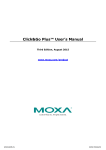
Port Expandable
The Intellio C320Turbo/PCI is composed of a Control Board, a DB25 to DB25
cable, some external modules. The Intellio C320Turbo/PCI supports expandability
from 8 to 32 ports for a single PC slot. Up to 128 ports could be used in the PC with
four Intellio C320Turbo/PCI installed.
PCI Solution
The board complies with PCI Spec. 2.1 and has neither switch nor jumper. Hardware
configuration for the IRQ number and memory addresses is automatically assigned
by PCI BIOS. Hence, it is a must to have the board plugged first before installing
software driver. For more PCI information, see appendix.
Intellio C320Turbo/P User's Manual
www.ipc2u.ru
1-1
www.moxa.pro
Low Host Processor Overhead
The Intellio C320Turbo/PCI is equipped with two high performance processors
(TMS320) on both the Control Board and the CPU/Basic Module and 512KB onboard memory to relieve the host’s CPU workload of all data and I/O handling tasks.
The memory buffer holds transmitted and received data to prevent data loss.
ASIC Design, Compact Size
The Intellio C320Turbo/PCI is also equipped with MOXA custom-designed ASIC
chip, which replaces lots of conventional IC and hence reduces the board to halfsize, increases the operation performance, and lowers the failure rate of the board.
Distance Extensible
Normally, a standard 2-meter DB25 to DB25 cable with 25 signal pins links the
Control Board to the external module. However, for the purpose of extending the
distance between Control Board and external modules to above 2 m and up to 100 m
(328 ft) or improving power insufficiency problem of the PC host, external power
and the cable specially fabricated with only 10 signal pins should be used as
illustrated in chapter 2 and chapter 5.
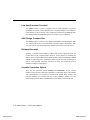
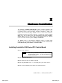
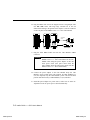
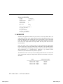
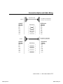
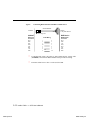
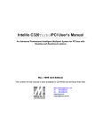
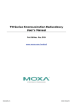
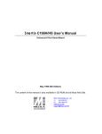
Versatile Connection Options
There are two connection options, Desktop and Rackmount, for the external
modules to meet various connection requirements. For Desktop option, CPU Module
and UART Modules are provided. For Rackmount option, Basic Module and
Extensive Modules are provided with rack mount capability. Besides, you may
choose flexibly from modules with DB25/RJ45, male/female, or RS-232/RS-422.
1-2 Intellio C320Turbo/PCI User's Manual
www.ipc2u.ru
www.moxa.pro
Introduction
U ART
M o d u le
U ART
M o d u le
CPU
M o du le
1
2
3
1
2
3
4
5
6
7
8
4
5
6
7
8
E x ten siv e M o du le
D B 2 5 to D B 2 5 C a ble
C 3 2 0 Turbo/P C I
B a sic M o d u le
Surge/Isolation Protection
To prevent the boards from damage caused by lightning or high potential voltage,
TVSS (Transient Voltage Surge Suppressor) and high potential difference protector
technologies are introduced in some connection options to protect the multiport
controller. This is critical to harsh environment such as factory, severe weather such
as lightning, or other high interference situations.
Status Indicator
The status of the communication lines is displayed on a row of diagnostic LED
indicators on the front panel of the external module, including TxD, RxD, DTR,
DSR, RTS, CTS, and DCD signals.
Major Operating System Support
It supports most popular O.S. platforms like Windows NT, Windows 95/98, SCO
UNIX/OpenServer, UNIX SVR4.2, Linux. MOXA device drivers feature easy
installation, configuration and better performance. In this manual, chapters for
MOXA Windows NT, Windows 95/98, and UNIX device drivers are included. For
other systems not mentioned, please contact Moxa dealer/distributor or Moxa or visit
the MOXA Web site for more information about newly available device drivers.
Intellio C320Turbo/PCI User's Manual
www.ipc2u.ru
1-3
www.moxa.pro
Powerful Serial Comm Developing Tools
For application development, MOXA provides the easy-to-use while powerful serial
communication library, including PComm under Windows NT, Windows 95/98 and
extended UNIX system calls. You can use this library to develop applications with
programming languages like Visual C++, Visual Basic, Borland C++, Borland
Delphi, UNIX C, etc. Utilities, such as monitor, terminal emulator, and diagnostics,
are included for debugging or monitoring the communication status or for terminal
emulation or file transferring.
Easy Installation
No matter hardware or software, installation are made as easy as possible. Follow the
installation guide to install and configure the hardware and the driver. Then, you can
start to use Intellio C320Turbo/PCI to transmit/receive data to/from the connected
devices, such as terminals, modems and printers, with ready-made or self-written
application programs.
Broad Applications
The Intellio C320Turbo/PCI is suitable for many applications. Here are a few:
Internet/Intranet Connection
Remote Access Application
Multi-user Application
Industrial Automation
Office Automation
Telecommunication
PC-based (vending) Machine or Kiosk System
Point-of-Sale (POS) System
Features
The following is a summary of all the outstanding features of
Intellio C320 Turbo/PCI:
❖ High speed serial communication-Up to 460.8 Kbps
❖ Low host CPU's overhead-Dual RISC processor architecture
❖ Reliability-On-chip hardware flow control guarantees no data loss
❖ Modular expandability-Easy to add ports for a single PC slot
❖ Supports full communication status display for each port
❖ Long range extensibility-Easy for long distance cable layout
1-4 Intellio C320Turbo/PCI User's Manual
www.ipc2u.ru
www.moxa.pro
Introduction
❖
❖
❖
❖
Rack mountable-Industrial standard 19” rack
Supports most popular OS-Windows NT, Windows 95/98, UNIX, Linux
Friendly user interface for configuration and utilities
Powerful but easy serial programming library and illustrative examples
Check List
Upon unpacking Intellio C320Turbo/PCI package, you should find the following
items:
❖
One Intellio C320Turbo/PCI Control Board
❖
One CPU Module or Basic Module
❖
One 2-meter DB25 to DB25 cable for connecting Control Board and
CPU/Basic Module. This item may not be needed if long range extension
kit is purchased
❖
For Desktop option, at least one and up to four 8-port RS-232/RS-422
female/male UART Module(s). For Rackmount option, up to 32 ports
of combination of 8-port or 16-port RS-232 Basic/Extensive Module(s).
❖
For Rackmount option, DB-37 to DB-37 cable(s) for connecting
Basic/Extensive Modules, if Extensive Module is used
❖
For Rackmount option, one 1.5-meter RJ-45 to male DB25 RS-232 cable for
testing
❖
Device driver diskettes:
Windows NT and Windows 95/98 Version 4.9 or above×1
PComm Lite Version 2.2 or above×1
UNIX Version 4.10 or above×1
❖
This Intellio C320Turbo/PCI User's Manual
❖
Fixing Kit for Desktop option. Or Rack Mount Kit for Rackmount option.
The following item may be included if long range extension is needed:
Long range extension kit
A power adapter for CPU/Basic Module, 90-240V AC auto-select
❖
A DB25 to DB25 cable which contains only 10 signal pins for connecting
Control Board and CPU/Basic Module
❖
❖
Intellio C320Turbo/PCI User's Manual
www.ipc2u.ru
1-5
www.moxa.pro
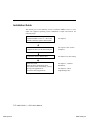
Installation Guide
This section gives a brief summary of how to install the Intellio C320Turbo/PCI
under each supported operating system. Installation is simple and involves the
following stages:
Check the PCI BIOS settings
Install the Intellio C320Turbo/PCI board
and the connection option (cable/module)
Install the software from the diskette
Configure the driver for the board and ports
Connect the devices with the cable
Restart the system
Check the driver initialization status
If the system restarts successfully, you may
develop your applications or
execute the desired applications
See chapter 2
See respective O.S. Section
in chapter 3
See chapter 5 for cable wiring
See chapter 3, “Software
Installation”
See chapter 4, “Serial
Programming Tools”
1-6 Intellio C320Turbo/PCI User's Manual
www.ipc2u.ru
www.moxa.pro
2
2
Hardware Installation
The installation of Intellio C320Turbo/PCI consists of hardware installation and
software installation. For software installation, please refer to the respective section
of operating systems in the next chapter. Hardware installation is stated in this
chapter. The no-switch-no-jumper Intellio C320Turbo/PCI board’s hardware
configuration for IRQ and memory addresses is automatically assigned by PCI
BIOS. Hence, it is a must to have the board plugged first before installing
software driver. After this, simply install the Control Board into the PC and then
connect one of the connection options, Desktop or Rackmount.
The Intellio C320Turbo/PCI hardware installation consists of Control Board
installation and external module installation. Make sure you have connected the
Control Board with proper number of external modules .
Installing the Intellio C320Turbo/PCI Control Board
Step 1:
Power off the PC.
Warning !
Make sure you switch off the system before installing
any PCI board.If you don’t, you may risk damaging your
system and the board.
Step 2:
Remove the PC’s cover.
Step 3:
Remove the slot cover bracket if present.
Step 4:
Plug the Intellio C320Turbo/PCI firmly into any free 32-bit PCI slot.
Step 5:
Fasten the holding screw to make the Control Board fixed.
Intellio C320Turbo/P User's Manual
www.ipc2u.ru
2-1
www.moxa.pro
Step 6:
Replace the system cover.
Note !
Each board must occupy one unique IRQ and one
unique memory address, which are assigned by PCI
BIOS automatically. However, you may select the free
IRQ number manually via PC’s BIOS setup for PCI slot,
but this method is not available for memory. The possible
IRQ numbers are 2(or 9), 3, 4, 5, 7, 10, 11, 12, and 15.
☞ Now the installation of the Control Board is complete. Continue to install
the external modules.
Installing the External Modules
There are two major connection options for the installation of external modules:
CPU and UART Modules for Desktop option or Basic and Extensive Modules for
Rackmount option.
Normally, a standard 2-meter DB25 to DB25 cable with 25 signal pins links the
Control Board to the external module. However, to extend the distance between
Control Board and external module to above 2 m and up to 100 m (328 ft) or to
improve power insufficiency problem of the PC host, external power for the
CPU/Basic Modules along with a cable specially fabricated with only 10 signal
pins should be used as illustrated in the next two subsections and in chapter 5 as well.
Otherwise, power degradation which comes from longer cable or power insufficiency
of PC host will cause system failure.
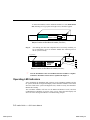
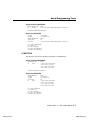
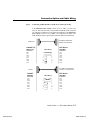
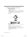
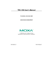
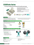
Installing the CPU and UART Modules (Desktop)
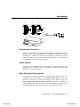
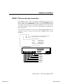
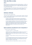
Step 7:
Connect the Intellio C320Turbo/PCI Control Board to the CPU Module
with the shipped DB25 to DB25 cable as shown in the following picture.
If range extension or external power is required, please use 10-signal-pin
cable coming with long range extension kit, instead. Thus, there are two
types of installation: without power adapter and with power adapter,
which are described as follows:
2-2 Intellio C320Turbo/PCI User's Manual
www.ipc2u.ru
www.moxa.pro
Hardware Installation
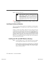
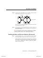
Without power adapter (for normal condition)
In most cases, you need not a power adapter.
A: Set the CPU Module power switch to the OFF position. This is
absolutely necessary when installing or removing the cable, the CPU
Module or the UART Module(s). Power should not be switched on
until you installed all components.
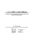
B: Plug the DB25 male end of the shipped 2-meter 25-signal-pin cable
into the connector on the rear panel of the Intellio C320Turbo/PCI
Control Board. Refer to the chapter 5 for the cable pinout details.
1
1
2
2
3
3
4
4
5
5
6
6
7
7
8
8
UART Module
UART Module
00
25-signal-pin Cable
C320 Turbo/PCI
CPU Module
C: Plug the other DB25 female end into the CPU Module’s DB25
connector.
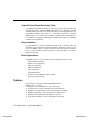
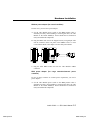
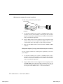
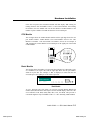
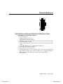
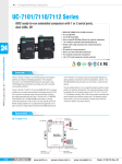
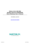
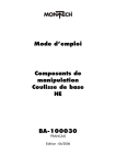
With power adapter (for range extension/external power
condition)
In case of range extension or external power requirement, you need a
power adapter.
A: Set the CPU Module power switch to the OFF position. This is
absolutely necessary when installing or removing the cable, the CPU
Module or the UART Module(s). Power should not be switched on
until you installed all components.
Intellio C320Turbo/PCI User's Manual
www.ipc2u.ru
2-3
www.moxa.pro
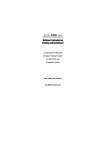
B: Plug the DB25 male end of the shipped 2-meter 10-signal-pin cable
(the link cable comes with long range extension kit or the one
fabricated according to the pinouts in the chapter 5) into the connector
on the rear panel of the Intellio C320Turbo /PCI Control Board.
1
1
2
2
3
3
4
4
5
5
6
6
7
7
8
8
UART Module
UART Module
10-signal-pin
Cable
00
CPU Module
C320 Turbo/PCI
Power Adapter
C: Plug the other DB25 female end into the CPU Module’s DB25
connector.
Warning! Do not use a 25-signal-pin cable to connect the
Intellio C320Turbo /PCI Control Board to the CPU
Module when using the power adapter as this will
cause power crash. (One power comes from the
power adapter while the other power comes from the
Intellio C320Turbo /PCI Control Board.)
D: Connect the power adapter to the CPU Module. Keep the CPU
Module’s power switch in the OFF position. If UART Module(s) is
(are) also required, keep the CPU Module’s power switch in the OFF
position until all necessary UART Module(s) is (are) installed.
E: Install the power adapter to a power source, either 110V or 220V AC.
Adjustment to the AC power specs is done automatically.
2-4 Intellio C320Turbo/PCI User's Manual
www.ipc2u.ru
www.moxa.pro
Hardware Installation
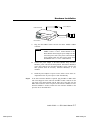
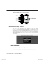
Step 8:
Connect the first UART Module to the CPU Module. Connect the second
UART Module to the first one if necessary and so on.
Metal Plate
Screws
To Control Board
UART Module
UART Module
CPU Module
For better fixation of modules, Fixing Kit is available and see the bottom
view of modules below to install.
Step 9:
After making sure that each component has been correctly installed, you
are recommended to power on the CPU Module first and then power on
the PC system secondly.
☞ Now the installation of the external CPU/UART modules is complete.
Continue to install the software driver explained in the chapter 3.
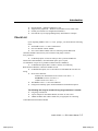
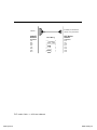
Installing the Basic and Extensive Modules (Rackmount)
Step 7:
Connect the Intellio C320Turbo/PCI Control Board to the Basic Module
with the shipped DB25 to DB25 cable as shown in the following picture.
If range extension or external power is required, please use 10-signal-pin
cable coming with long range extension kit, instead. Thus, there are two
types installation: without power adapter and with power adapter,
which are described as follows:
Intellio C320Turbo/PCI User's Manual
www.ipc2u.ru
2-5
www.moxa.pro
Without power adapter (for normal condition)
In most cases, you need not a power adapter.
Extensive Module
25-singal-pin Cable
C320 Turbo/PCI
Basic Module
A:
Set the Basic Module power switch to the OFF position. This is
absolutely necessary when installing or removing the cable, the Basic
Module or the Extensive Module(s). Power should not be switched on
until you installed all components.
B:
Plug the DB25 male end of the shipped 2-meter 25-signal-pin cable
into the connector on the rear panel of the Intellio C320Turbo/PCI
Control Board. Refer to the chapter 5 for the cable pinout details.
C:
Plug the other DB25 female end into the Basic Module’s DB25
connector.
With power adapter ( for range extension/external power condition)
In case of range extension or external power requirement, you need a
power adapter.
A:
Set the Basic Module power switch to the OFF position. This is
absolutely necessary when installing or removing the cable, the Basic
Module or the Extensive Module(s). Power should not be switched on
until you installed all components.
B:
Plug the DB25 male end of the shipped 2-meter 10-signal-pin cable
(the link cable comes with long range extension kit or the one
fabricated according to the pinouts in chapter 5) into the connector on
the rear panel of the Intellio C320Turbo/PCI Control Board.
2-6 Intellio C320Turbo/PCI User's Manual
www.ipc2u.ru
www.moxa.pro
Hardware Installation
Extensive Module
Power Adapter
10-singal-pin C able
C 320 Turbo/PC I
Basic Module
C:
Plug the other DB25 female end into the Basic Module’s DB25
connector.
Warning!
Step 8:
Do not use a 25-signal-pin cable to connect the
Intellio C320Turbo/PCI Control Board to the
Basic Module when using the power adapter as this
will cause power crash. (One power comes from the
power adapter while the other power comes from
the Intellio C320Turbo/PCI Control Board)
D:
Connect the power adapter to the Basic Module. Keep the Basic
Module’s power switch in the OFF position. If Extensive Module(s)
is(are) also required, keep the Basic Module’s power switch in the
OFF position until all necessary Extensive Module(s) is (are)
installed.
E:
Install the power adapter to a power source, either 110V or 220V AC.
Adjustment to the AC power specs is done automatically.
If one more Extensive Module is required, plug the DB37 to DB37 male
end of the shipped 1-meter cable into the DB37 female connector on the
rear panel of the Basic Module and the other end of the cable into the
DB37 male connector on the rear panel of the Extensive Module. If more
Extensive Module is needed, connect the next Extensive Module to the
previous one as described above.
Intellio C320Turbo/PCI User's Manual
www.ipc2u.ru
2-7
www.moxa.pro
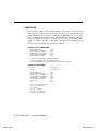
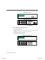
To mount the module(s) on the industrial standard 19” rack, Rack Mount
Kit, including two L-type plates and eight screws, should be applied.
Multiport
Controller
BASICMODULE
Power TxD RxD DTR DSR RTS CTS DCD
Module
Channel
L-type Plate
L-type Plate
Multiport Controller with Rack Mount Kit installed ( Front View )
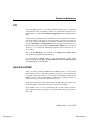
Step 9:
After making sure that each component has been correctly installed, you
are recommended to power on the Basic Module first and then power on
the PC system secondly.
L-type Plate
L-type Plate
Multiport Controller with Rack Mount Kit installed ( Rear View )
☞
Screw
Now the installation of the external Basic/Extensive module is complete.
Continue to install the software driver explained in chapter 3.
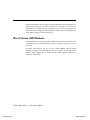
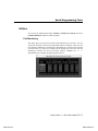
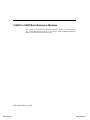
Operating LED Indicators
After completing the installation and powering on the CPU/Basic Module and the
PC system, check the two-digit LED display on the CPU/Basic Module. These LEDs
show the results of the system self-diagnostic tests, which are run by the CPU/Basic
Module after startup.
The CPU/Basic Module will first test the ROM and RAM of itself, and then
UART/Extensive Module(s) if present. If any error is found, the LED display will
show one of the messages described in “Troubleshooting” chapter.
2-8 Intellio C320Turbo/PCI User's Manual
www.ipc2u.ru
www.moxa.pro
Hardware Installation
If the first test passed, the CPU/Basic Module will then display “Ld” waiting for
loading firmware from the Intellio C320Turbo/PCI Control Board. After loading
the firmware, the CPU Module will scan for the number of UART Modules or the
number of ports available. The LED will show the last accessible port.
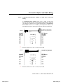
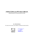
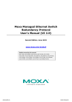
CPU Module
The left digit shows the UART Module number and the right digit shows the last
port number within a UART Module. The UART Module closest to the CPU
Module is of number 1. The next module is of number 2, and so on. For example, if
“48” is displayed, it means that the last accessible port is the eighth port of the fourth
UART Module.
T R D D R C D
X X T S T T C
D D R R S S D
48
MODULE
CHANNEL
CPU Module
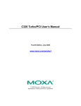
Basic Module
The left digit shows the number of 8-port unit that configured (if continuous 8 ports
are considered as an 8-port unit) and the right digit shows the last port number
within an 8-port unit. For example, if “48” is displayed, it means that the last
accessible port is the eighth port of the fourth 8-port unit.
Multiport Controller
Ba s i c
48
M﹙
o﹙
d﹙
u﹙
l e
Power
TxD
RxD
DTR
DSR
RTS
CTS
DCD
Module Channel
Basic Module
To see a particular port’s line status, you can keep pressing Module Button and
Channel (Port) Button till the desired port is shown on LED display, then look at the
seven indicators TxD, RxD, DTR, DSR, RTS, CTS, and DCD. This provides a
convenient diagnostic ways for Intellio C320Turbo/PCI. Normally, DTR and RTS
Intellio C320Turbo/PCI User's Manual
www.ipc2u.ru
2-9
www.moxa.pro
indicators will light on when local port is opened while DSR and CTS indicators will
light on when remote port is opened. TxD indicator will light on if local port is
transmitting data and RxD indicator will light on if local port is receiving data (or
remote port is transmitting data). DCD indicator is mostly useful to detect phone line
carrier when a modem is connected to the port.
Mix of Various UART Modules
UART Modules with various functions are produced for different requirements, such
as RS-232/RS-422, female/male DB25 connector, isolation protection or surge
protection.
No matter what interfaces they use, any two UART Modules could be mixed
(connected) together freely depending on needs. For example, you may put 2 male
RS-232 UART Modules and 2 female RS-422 UART Modules together for
application consideration.
2-10 Intellio C320Turbo/PCI User's Manual
www.ipc2u.ru
www.moxa.pro
3
3
Software Installation
In this chapter, software driver installation, configuration and driver update/removal
procedures are described for various operating systems, including Windows NT,
Windows 95/98 and UNIX. Before proceeding with software installation, complete
the hardware installation detailed in the previous chapter.
However, if you need to develop applications, refer to the next chapter, “Serial
Programming Tools”, for more information.
Windows NT
Windows NT supports up to 256 serial ports, from COM1 to COM256. To fully
integrate the advanced features of Windows NT, multi-process and multi-thread,
pure 32-bit Windows NT device drivers are developed for Intellio C320Turbo/PCI
and other MOXA multiport boards. The drivers conform to Win32 COMM API
standard.
If you install the driver for the first time, please go directly to the section “Installing
Driver”.
If you already have installed the driver and want to re-configure the board and port,
add more boards or delete boards, please refer to the section “Configuring Board and
Port”.
If you want to update or even remove driver, please go to the section “Updating
Driver” and section “Removing Driver”.
If you want to remove boards, please simply unplug the desired boards from the
system.
Intellio C320Turbo/P User's Manual
www.ipc2u.ru
3-1
www.moxa.pro
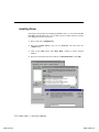
Installing Driver
Following is the procedure for installing the Intellio C320Turbo/PCI driver for the
first time under Windows NT 3.51/4.0. Make sure the board(s) has(have) already
been plugged in the PCI slot of the PC.
1. Please Login NT as Administrator.
2. Open the [Control Panel], click on the [Network] icon and select the
[Adapters] tab.
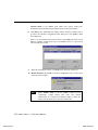
3. Click on the [Add] button, then [Have Disk...] button in “Select Network
Adapter”.
4. Specify the exact path of the driver diskette, A:\WINDOWS.NT. Click [OK].
3-2 Intellio C320Turbo/PCI User's Manual
www.ipc2u.ru
www.moxa.pro
Software Installation
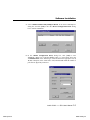
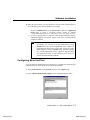
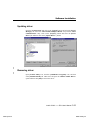
5. Select “MOXA Intellio Family Multiport Board” in the “Select OEM Option”
dialog box, and click [OK] to enter the “MOXA Configuration Panel” dialog
box to start the installation.
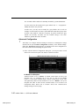
6. In the “MOXA Configuration Panel” dialog box, click [Add] to enter
“Property” dialog box to add the Intellio C320Turbo/PCI board. Select the
“C320Turbo/PCI” in the “Board Type” field and choose the appropriate one, 8,
16, 24, or 32 ports, in the “Total Ports” field, which should match the number of
ports that are physically connected.
Intellio C320Turbo/PCI User's Manual
www.ipc2u.ru
3-3
www.moxa.pro
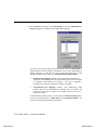
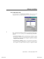
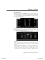
7. In the “Property” dialog box, click [Port Setting] to enter the “Individual Port
Setting” dialog box to change the port COM number mappings.
You have to set up all the ports of the board with the desired “COM number”,
which should not conflict with other COM number in use. In this “Individual Port
Setting” dialog box, you may have two ways to map the physical ports to COM
numbers depending on the check box “Auto Enumerating COM number”.
D
Sequential Port Mapping: (Enable “Auto Enumerating COM number”)
Specify the COM number of the first port and subsequent ports are mapped
to continuous COM numbers. For instance, if first port is mapped to
COM10, then second port is mapped to COM11 sequentially.
D
Non-sequential Port Mapping: (Disable “Auto Enumerating COM
number”) Specify the COM number for individual port. For instance, the
second port can be out of sequence, say COM18, while the first port is
mapped to COM10.
In “Individual Port Setting” dialog, you may click on [Advanced Setting] button
to tune the advanced features, “UART FIFO” and “Transmission Mode”, for
each port for particular performance requirements.
3-4 Intellio C320Turbo/PCI User's Manual
www.ipc2u.ru
www.moxa.pro
Software Installation
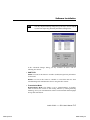
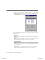
Note !
You may skip the following settings and go directly to the next step 8
if you do not require any particular performance tuning for the
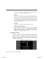
In the “Advanced Settings” dialog, you may customize the driver with the
following two features:
D UART FIFO
Enable: You can set this feature to “Enable” (default) and gain best performance
for the board.
Disable: You can set this feature to “Disable” to avoid from data loss when
communicating with communication devices using S/W flow control.
D Transmission Mode
Hi-Performance Mode: This feature is set to “Hi-Performance” by default,
which accelerates the reaction of data writing behavior by utilizing buffering
technology. It lets your communication software reach maximum data throughput
in large data transmission.
Intellio C320Turbo/PCI User's Manual
www.ipc2u.ru
3-5
www.moxa.pro
Classical Mode: It lets MOXA ports behave like generic COM ports.
Transmission for small data packets would be more precisely and reliable.
8. Click [OK] in the “Individual Port Setting” and the “Property” dialog boxes to
go back to the “MOXA Configuration Panel” dialog box. Click [OK] to finish
the configuration.
However, if you installed more than one board, click [Add] and repeat steps 6
and 7 to configure another board. Up to four Intellio C320Turbo/PCI boards
can be installed in a system.
9.
When the configuration is done, click [OK] in the “Network” dialog box.
10. Restart Windows NT system. The latest configuration will not take effect
unless the system restarts.
Note !
Please double check if all the Intellio C320Turbo/PCI
components: Control Board, link cable and external
cable/module, are connected and fastened tightly to make sure
that the system and the driver start successfully later.
3-6 Intellio C320Turbo/PCI User's Manual
www.ipc2u.ru
www.moxa.pro
Software Installation
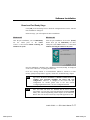
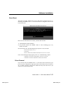
11. Once the system restarts, you may check the event log issued by MOXA drive to
see if the ports of the board are initialized successfully.
Enter the [Administrative] group, [Event Viewer] and select [Application
Event Log] to check a successful message similar to “MOXA
C320Turbo/PCI Multiport Board #1: addr(XXX) O.K.” for each configured board.
D
If an error message similar to “MOXA C320Turbo/PCI Multiport Board #1
addr(XXX): IRQ(10) test failure!” appears, refer to the “Troubleshooting”
chapter for solutions.
Note !
Once the board and driver are installed and the system restarts
successfully, you can start to develop applications by using
PComm library (See “Serial Programming Tools” chapter) or
using Microsoft Win32 API. you can also execute any readymade application, such as PComm utility Terminal emulator
(See “Serial Programming Tools” chapter) or HyperTerminal
to transmit/receive data, as well as Remote Access Service to
provide dial-up networking capability.
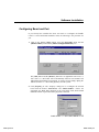
Configuring Board and Port
If you already have installed the driver and want to re-configure the board and port,
add more boards or delete boards, please follow this procedure.
1. Open [Control Panel], click [Network] and select the [Adapters] tab.
2. Select “MOXA Intellio Family Adapter” in the “Installed Adapter Cards:”.
Intellio C320Turbo/PCI User's Manual
www.ipc2u.ru
3-7
www.moxa.pro
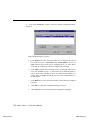
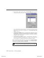
3. Click on the [Properties...] button to enter the “MOXA Configuration Panel”
dialog box.
In this configuration panel, you may:
D
Click [Property] to enter “Property” dialog box to configure the selected
board with the correct “Total Ports” and “COM Number”. Please see
steps 6 to 8 in the previous section, “Installing Driver”, for more details,
except that the “Board Type” field is not supposed to be changed.
D
Click [Add] to add one more board that is not yet configured in the system.
Up to four of Intellio C320Turbo/PCI boards can be installed together as
long as the memory and IRQ resources are sufficient and available in a
system. Please see steps 6 to 8 in the previous section, “Installing Driver”,
for more details.
D
Click [Remove] to remove the board currently selected from the configured
board list.
D
Click [OK] to confirm the configuration changes you made.
D
Click [Cancel] to leave the dialog with the configuration unchanged.
3-8 Intellio C320Turbo/PCI User's Manual
www.ipc2u.ru
www.moxa.pro
Software Installation
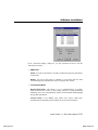
Adding/Removing Board
Following is the procedure to add/remove Intellio C320Turbo/PCI Series boards
after a first time installation. Note that the presence of the board(s) is(are)
required for adding boards.
1.
2.
3.
4.
Power off the system.
Plug/unplug the boards in the system.
Power on the system.
Run the software configuration “MOXA Configuration Panel” to add/remove the
boards, detailed in the previous “Configuring the Board and Port” section.
Updating Driver
To update the driver for the Intellio C320Turbo/PCI board, simply remove the
driver, as described in the next section, and then reinstall it as detailed in the
“Installing Driver” section.
Removing Driver
To remove the driver for the Intellio C320Turbo/PCI board,
1. Open the [Control Panel], click on the [Network] icon and select the
[Adapters] tab.
2. Select “MOXA Intellio Family Adapter” in the adapter list, then click on the
[Remove] button and the [OK] button to remove the driver.
3. Restart the system to activate the new configuration.
Intellio C320Turbo/PCI User's Manual
www.ipc2u.ru
3-9
www.moxa.pro
Windows 95/98
Windows 95/98 supports up to 128 serial ports, from COM1 to COM128. To fully
integrate the advanced features of Windows 95/98, multi-process and multi-thread,
pure 32-bit Windows 95/98 virtual device port drivers (VxD) compliant with
communication driver (VCOMM) are developed for Intellio C320Turbo/PCI and
other MOXA multiport boards. The drivers conform to Win32 COMM API
standard.
If you install the driver for the first time or you want to install more boards, please
go directly to the section “Installing Driver”.
If you already have installed the driver and want to re-configure the board, please
refer to the section “Configuring Board and Port”.
If you want to update or even remove driver, please go to the section “Updating
Driver” and secton “Removing Driver”.
If you want to remove boards, please simply unplug the undesired boards from the
system.
Installing Driver
If you install for the first time, or you want to install more boards, this section is for
you.
You can easily plug the Intellio C320Turbo/PCI board and work right away with
very little installation efforts under Windows 95/98, which supports Plug and Play
capability. The Windows 95/98 will automatically detect the presence of the newly
plugged board and prompt you to install the software driver the first time. In this
case, you need the driver diskette.
Up to four Intellio C320Turbo/PCI boards can be installed together as long as the
memory addresses and IRQ number resources are sufficient and available in a
system.
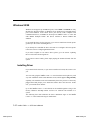
The following flow chart illustrates the driver installation stages of the Intellio
C320Turbo/PCI board. Each stage is detailed later.
3-10 Intellio C320Turbo/PCI User's Manual
www.ipc2u.ru
www.moxa.pro
Software Installation
Install the Intellio PCI board in the system
See chapter, “Hardware
Installation”
Start Windows 95/98 to detect the board
Yes
Driver installed before?
No
Install the driver with the diskette
See “First Time Driver Installation
Stage”
Configure the board and port
See “Port Configuration Stage”
Ports of Intellio C320 Turbo/PCI board
are ready to work.
See “Board and Port Ready Stage”
Intellio C320Turbo/PCI User's Manual
www.ipc2u.ru
3-11
www.moxa.pro
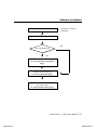
First Time Driver Installation Stage
The stage presents the steps for installing the driver for the first time with the first
Intellio C320Turbo/PCI board. The installation of Intellio C320Turbo/PCI board
for Windows 95 and Windows 98 differs slightly and will be described in two
columns. Follow the steps in the left or right column for Windows 95 or 98,
respectively.
1. Upon detecting the first new Intellio C320Turbo/PCI board, Windows 95/98
will automatically show a ”New hardware found” message box and then display
the following dialog box. Click on the [Next>] button.
Windows 95
Windows 98
2. Click on the [Other Location] button.
2. Select “Display a list ...” and click [Next>].
3-12 Intellio C320Turbo/PCI User's Manual
www.ipc2u.ru
www.moxa.pro
Software Installation
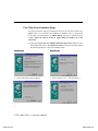
3.Type “A:\Windows.95” in the Location field,
and click [OK]. The system will start reading the
files from the diskette.
3. Selct “Other Devices” and click [Next>].
4. Clink on the [Finish] button.
4. Click on the [Have Disk] button.
5. Type “A:\Windows.95” and click [OK]. The
system will start reading the files from the
diskette.
Intellio C320Turbo/PCI User's Manual
www.ipc2u.ru
3-13
www.moxa.pro
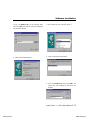
6. Click [Next>].
7. Click [Next>].
3-14 Intellio C320Turbo/PCI User's Manual
www.ipc2u.ru
www.moxa.pro
Software Installation
Port Configuration Stage
This stage displays the “C320Turbo/PCI Installation” dialog box for the port
configuration. Here you can map the MOXA ports to the system COM numbers.
In the “C320Turbo/PCI Installation” dialog box, you can map the physical ports to
COM numbers in two ways depending on the “Auto Enumerating COM number”
check box.
DSequential Port Mapping: (Enable “Auto Enumerating COM number”) Specify
the COM number of the first port and subsequent ports are mapped to continuous
COM numbers. For instance, if first port is mapped to COM10, then second port
is mapped to COM11 sequentially.
DNon-sequential Port Mapping: (Disable “Auto Enumerating COM number”)
Specify the COM number for individual port. For instance, the second port can be
out of sequence, say COM18, while the first port is mapped to COM10.
Intellio C320Turbo/PCI User's Manual
www.ipc2u.ru
3-15
www.moxa.pro
In addition, in the “C320Turbo/PCI Installation” dialog box, you may click on
[Advanced Settings] button to tune the advanced features, “UART FIFO” and
“Transmission Mode”, for each port for particular performance requirements.
In the “Advanced Settings” dialog box, you may customize the driver with the
following two features:
D UART FIFO
Enable: You can set this feature to “Enable” (default) and gain best performance
for the board.
Disable: You can set this feature to "Disable" to avoid from data loss when
communicating with communication devices using S/W flow control.
D Transmission Mode
Hi-PerformanceMode: This feature is set to “Hi-Performance” by default,
which accelerates the reaction of data writing behavior by utilizing buffering
technology. It lets your communication software reach maximum data throughput
in large data transmission.
Classical Mode: It lets MOXA ports behave like generic COM ports.
Transmission for small data packets would be more precisely and reliable.
3-16 Intellio C320Turbo/PCI User's Manual
www.ipc2u.ru
www.moxa.pro
Software Installation
Board and Port Ready Stage
Click [OK] for all the dialog boxes to finish the configuration and exit the “MOXA
Ports Installation” dialog box.
In this last stage, you will complete the driver installation.
Windows 95
Windows 98
After the port installation, you can immediately
use the COM ports of the Intellio
C320Turbo/PCI board without restarting the
Windows 95 system.
After the port installation, click on the [Finish]
button. Now you can immediately use those
COM ports of the Intellio C320Turbo/PCI board
without restarting the Windows 98 system.
Once the installation is finished, error conditions of the board, if any, are displayed
on the screen. Otherwise, everything should be fine.
If an error message similar to “C320Turbo/PCI (BusNo=x, DevNo=x) at base
memory [XXX] interrupt failure!” appears, consult the “Troubleshooting” chapter.
Note !
Up to now, the driver installation of Intellio C320Turbo/PCI is
complete and successful, including the board and port
configuration. However, if changes of the board and port
configuration are needed, please refer to the next section,
“Configuring Board and Port”, for more configuration details.
Note !
Once the board and driver are installed and the driver restarts
successfully, you can start to develop applications with the PComm
library (See “Serial Programming Tools” chapter) or the Microsoft
Win32 API. You can also execute any ready-made application, such
Intellio C320Turbo/PCI User's Manual
www.ipc2u.ru
3-17
www.moxa.pro
PComm utility Terminal emulator (See “Serial Programming Tools”) or
HyperTerminal to transmit/receive data, as well as Remote Access
Service to provide dial-up networking capability.
☞
☞
If multiple boards are installed at the same time, the same scenario applies
for the next boards, except that no driver diskette is asked any more.
Similarly, if you want to add more boards and the driver has been installed
before, simply plug the Intellio C320Turbo/PCI board and Windows
95/98 will automatically detect and install the required driver.
3-18 Intellio C320Turbo/PCI User's Manual
www.ipc2u.ru
www.moxa.pro
Software Installation
Configuring Board and Port
If you already have installed the driver and want to re-configure the Intellio
C320Turbo/PCI board under Windows 95/98, the following is the procedure for
you.
1. Click on the Taskbar [Start] button, select the [Programs] menu, and the
[MOXA Utilities] menu and the [MOXA Configuration Panel] icon.
The [Add] button and the [Remove] button are not applicable in PCI case. A
new C320Turbo/PCI board will be automatically found as new hardware and
added during the Windows 95/98 startup. To remove a board, simply unplug the
undesired C320Turbo/PCI board physically from the system.
2. Click [Property] to enter “Property” dialog box to re-configure the selected
board with the desired “Total Ports” and “COM Number”. Choose the
appropriate one, 8, 16, 24, or 32 ports, in the “Total Ports” field, which should
match the number of ports that will be physically connected.
Intellio C320Turbo/PCI User's Manual
www.ipc2u.ru
3-19
www.moxa.pro
3. In the “Property” dialog, you may click on the [Port Setting] button to enter the
“Individual Port Setting” dialog box to change the port COM number mappings.
In the “Individual Port Setting” dialog box, you may have two ways to map the
physical ports to COM numbers depending on the “Auto Enumerating COM
number” check box.
D
Sequential Port Mapping: (Enable “Auto Enumerating COM number”) Specify
the COM number of the first port and subsequent ports are mapped to continuous
COM numbers. For instance, if first port is mapped to COM10, then second port
is mapped to COM11 sequentially.
D
Non-sequential Port Mapping: (Disable “Auto Enumerating COM number”)
Specify the COM number for individual port. For instance, the second port can
be out of sequence, say COM18, while the first port is mapped to COM10.
In the “Individual Port Setting” dialog box, you may click on [Advanced Settings]
button to tune the advanced features, “UART FIFO” and “Transmission Mode”,
for each port for particular performance requirements.
Note !
You may skip the following settings and go directly to the next step 4,
if you do not require any particular performance tuning for the driver.
3-20 Intellio C320Turbo/PCI User's Manual
www.ipc2u.ru
www.moxa.pro
Software Installation
In the “Advanced Settings” dialog box, you may customize the driver with the
following two features:
D UART FIFO
Enable: You can set this feature to “Enable” (default) and gain best performance
for the board.
Disable: You can set this feature to "Disable" to avoid from data loss when
communicating with communication devices using S/W flow control.
D Transmission Mode
Hi-PerformanceMode: This feature is set to “Hi-Performance” by default,
which accelerates the reaction of data writing behavior by utilizing buffering
technology. It lets your communication software reach maximum data throughput
in large data transmission.
Classical Mode: It lets MOXA ports behave like generic COM ports.
Transmission for small data packets would be more precisely and reliable.
Intellio C320Turbo/PCI User's Manual
www.ipc2u.ru
3-21
www.moxa.pro
4.
Click [OK] in the “Individual Port Setting” and the “Property” dialog boxes to
go back to the “MOXA Configuration Panel” dialog box. Click [OK] to finish
the configuration.
5.
Restart Windows 95/98 system if you have changed any setting. The latest
configuration will not take effect unless the system restarts.
3-22 Intellio C320Turbo/PCI User's Manual
www.ipc2u.ru
www.moxa.pro
Software Installation
Updating driver
Open the [Control Panel] and click on the [System] button, and select the [Device
Manager] tab. Select the “Moxa Intellio Multiport Board” entry and the “Moxa
C320Turbo/PCI” entry. Click on the [Property] button and select the [Device
Driver] tab and then click on the [Update Driver...] button.
Removing driver
Open [Control Panel] icon, and then [Add/Remove Programs] icon, and then
select [Install/Uninstall] tab. Then select and open the “MOXA Intellio Driver”
option and then enter [OK] to remove the driver.
Intellio C320Turbo/PCI User's Manual
www.ipc2u.ru
3-23
www.moxa.pro
UNIX
Installing Driver
Up to four boards of combination of Intellio C320Turbo/PCI and C320Turbo can
be installed together as long as memory resources are sufficient and available in a
system.
Step 1.
Boot the system and login from the console as a super user (root).
Step 2.
Insert the driver diskette into a 1.44MB floppy drive, A: or B:.
If the driver files are obtained from the MOXA FTP service, put them
under the /tmp/moxa directory and skip to the step 5.
Step 3.
Change to the root directory by entering the following command:
# cd /
Step 4.
Enter the following command to extract the installation script file first.
# tar xvf /dev/fd0135ds18 /tmp/moxa/mxinstall (if 1.44MB A:)
Step 5.
# /tmp/moxa/mxinstall
Follow the instructions prompted to finish the driver installation
Copyright (C) 199x Moxa Technologies Co., Ltd. All Rights Reserved.
MOXA UNIX Device Driver Installation Ver. x.x
Please select one of the following OS:
1. SCO UNIX
2. UNIX SVR4.2
3. XENIX
Select:
Please type 1 for SCO UNIX 3.2.x, SCO OpenServer
or SCO Open Desktop. Type 2 for UNIX SVR4.2,
UnixWare or MITUX. Type 3 for XENIX.
Please select one of the devices where the driver diskette/files put:
3-24 Intellio C320Turbo/PCI User's Manual
www.ipc2u.ru
www.moxa.pro
Software Installation
1. /dev/fd0135ds18
2. /dev/fd096ds15
3. /dev/fd1135ds18
4. /dev/fd196ds15
5. Hard Disk
(A: 1.44MB)
(A: 1.2 MB)
(B: 1.44MB)
(B: 1.2 MB)
/tmp/moxa
Select:
Please type 1, 2, 3, 4 or 5.
Step 6.
The MOXA Multiport Board Installation Utility dialog will show for
driver installation. When finished, press any key to continue.
SCO UNIX or SCO OpenServer or XENIX
You will be prompted to rebuild kernel at this moment and you are
recommended to do so unless you need to install other driver. Please
type “y”. After kernel rebuild, please shutdown the system on your
own.
UNIX SVR4.2 or UnixWare or MITUX
You will be prompted to shutdown the system on your own for
kernel rebuilding and you are recommended to do so.
Step 7.
Once the system reboots, run “mxadm” to configure the board and port.
Select and open “Basic Configuration” to do the basic board and port
configuration. You may further optionally select and open “Advanced
Configuration” to do the advanced settings.
Select and open “Board Reset” to reset the driver and board for the latest
configuration to take effect.
☞
For more details, see later section, “Administration Utility - mxadm”.
Up to now, you have already completed the whole installation and the
Intellio C320Turbo/PCI board is ready to work.
Note!
Please double check if all the Intellio C320Turbo/PCI
components: Control Board, link cable and external modules
are connected and fastened tightly to make sure that the system
and the driver starts successfully.
Intellio C320Turbo/PCI User's Manual
www.ipc2u.ru
3-25
www.moxa.pro
☞
Now you can run any ready-made applications such as getty terminal
or PPP/SLIP. You can also start to develop applications with
Standard UNIX system calls, as well as MOXA extended UNIX Ioctl()
Commands. (See “Serial Programming Tools” chapter)
3-26 Intellio C320Turbo/PCI User's Manual
www.ipc2u.ru
www.moxa.pro
Software Installation
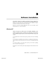
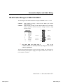
MOXA TTY Device Naming Convention
If the Intellio C320Turbo/PCI is successfully configured, there will be two tty
devices created for each port at /dev directory: one is non-MODEM tty (e.g.
ttya11), and the other is MODEM tty (e.g. ttyA11). The two devices are actually
accessing the same physical port except that the MODEM tty has to check the ON
status of DCD signal to be able to open device, and closing device automatically as
DCD signal is OFF.
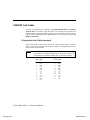
The convention of the MOXA tty device name is /dev/tty{a-d}{1-4}{1-8}, where (if
continuous 8 ports are viewed as an 8-port unit for Intellio C320Turbo/PCI
Rackmount):
"tty" + "A" + "B" + "C"
Port ordinal number in a UART Module/8-port unit,1-8
UART Module/8-port unit ordinal number,1-4
Board ordinal number
"a"or "A":
1st MOXA board
"b"or "B":
2nd MOXA board
"c"or "C":
3rd MOXA board
"d"or "D":
4th MOXA board
Capitals indicate a MODEM port
Standard tty device prefix
To next module
P1
P8
From PC
/dev/ttya18
/dev/ttya17
/dev/ttya16
/dev/ttya15
/dev/ttya14
/dev/ttya13
/dev/ttya12
/dev/ttya11
DC IN
ON/OFF
Basic Module
Intellio C320Turbo/PCI User's Manual
www.ipc2u.ru
3-27
www.moxa.pro
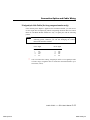
Taking 8 port Intellio C320Turbo/PCI as an example,
/dev/ttya11
1
/dev/ttya12
2
/dev/ttya13
3
/dev/ttya14
4
/dev/ttya15
5
/dev/ttya16
6
/dev/ttya17
7
/dev/ttya18
8
UART Module
To Control Board
I8
CPU Module
Administration Utility - mxadm
You can use the administration utility, mxadm, to change the Intellio
C320Turbo/PCI basic and advanced configuration, to reset the board, to tune
performance and to remove the installed MOXA driver from the UNIX system,
which are detailed as follows. For the details of the rest utilities: port monitoring,
and terminal emulator, please refer to “UNIX” section of “Serial Programming
Tools” chapter.
Basic Configuration
This utility is to configure basic settings for the driver.
1. In the “Basic Configuration” dialog box, you should first press Enter in the
3-28 Intellio C320Turbo/PCI User's Manual
www.ipc2u.ru
www.moxa.pro
Software Installation
“Board type” field to select board type, C320Turbo/PCI. And a list of Intellio
C320Turbo/PCI boards found available is for you to select. Normally, one
choice is available if there is one Intellio C320Turbo/PCI board installed
beforehand.
Secondly, select number of ports in the “Ports” field to match exactly the
number of ports physically connected.
Press Enter on the desired entry of the list to select. Now the selected Intellio
C320Turbo/PCI board is configured with BIOS assigned memory address and
Bus/Device numbers as shown.
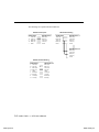
2. Press Page Down to enter “getty Setting” sub-dialog, there are some noticeable
fields for initialize the port for getty usage. You may skip this step if you will not
use getty utility.
Non-Modem and Modem Baud Rate
This field stands for the initial baud rate symbol and hunt sequence for NonModem /Modem tty. It is simply for setting parameters of getty entries in system
Intellio C320Turbo/PCI User's Manual
www.ipc2u.ru
3-29
www.moxa.pro
file /etc/inittab which could also be manually modified by system administrator.
Its value comes from the UNIX system “getty default” file, i.e., “/etc/gettydefs”.
Modify this field to suit your need.
In some cases, you may need to modify the “getty default” file as well. For
example, in some UNIXs, the “9600” symbol indicated 8-data-bit no-parity while
in others it may stand for 7-data-bit, even-parity. So, please examine the “getty
default” file carefully, and make sure the terminal settings is the same.
Otherwise, garbled data will be inevitable.
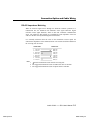
Advanced Configuration
This utility is to configure advanced settings for the driver, excluding basic settings
described in the previous Basic Configuration. Similarly, in the “Board Settings”
dialog box, board reset (described later) is available for the latest configuration to
take effect without kernel rebuilding and system reboot.
1. In the “Advanced Board Configuration” dialog box, you can press Enter in each
field to select the desired option. The fields are detailed as follows.
On Board Line Discipline
Advanced feature is set to “Enable” by default, which means all the tty line
discipline jobs, e.g. translating NL to CR, will be done on the Intellio
C320Turbo/PCI board (Terminal mode), instead of doing them on host. This
will significantly reduce the host workload. If it is set to “Disable”, the tty line
discipline will either be done on host (Terminal mode) or be not done at all
(Transparent mode). Please refer to “Feature” field in the “Advanced Port
Settings” dialog box on next page.
3-30 Intellio C320Turbo/PCI User's Manual
www.ipc2u.ru
www.moxa.pro
Software Installation
Baud Rate Mapping
This advanced feature is set to “High Band” by default, indicating that the baud
rate 50, B50, will no longer stand for 50 bps. Instead, B50 means 57600 bps, B75
is for 115.2 Kbps, B110 is for 230.4 Kbps, and B134 is for 460.8 Kbps. You may
press F1 Help for on-line details.
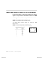
2.
Press PageDown to enter the “Advanced Port Settings” sub-dialog, there are
some noticeable fields to initialize the ports for advanced usage. You may skip
this step if you do not concern these features.
Feature
In the “Port Feature Settings” sub-dialog, port feature [Terminal] is the only
choice if On Board Line Discipline is set to “Enable”. This is good for terminal
application.
However, if On-Board Line Discipline is set to “Disable”, port feature could be
either [Transparent] or [Terminal]. In case of [Terminal], all the tty line
discipline jobs will be done on host which surely is a burden to the host. In case
of [Transparent], no time-consuming tty line discipline is applied for the port
Intellio C320Turbo/PCI User's Manual
www.ipc2u.ru
3-31
www.moxa.pro
except flow control, thus non-terminal applications such as data acquisition will
benefit from it, e.g. gain better throughput and performance.
Response
Three levels, Slow, Normal and Fast, of port response time are designed for
your need. Ports with faster response time will consume more host CPU's
resource while slower response consumes less resource. The response time for
those ports with normal or slow response can be further tuned by the response
level in “Performance Tuning” menu. In addition, if the port feature is set to
On-board Line Discipline “Disable” and Feature “Terminal”, response option
will be locked at “Slow” level.
UART FIFO
This feature is set to “Enable” by default and is not able to change.
RTS/CTS Hardware Flow Control
This feature controls the hardware flow control feature. If set to “Disable”
(default), CTS signal is not needed for tty port to transfer data and RTS/CTS
hardware flow control function in driver is disabled. On the contrary, if set to
“Enable”, CTS signal is needed for tty port to transfer data and RTS/CTS
hardware flow control function in driver is enabled.
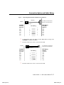
Performance Tuning
The utility let you tune the driver to the desired response time for those ports with
Resp = Norm or Slow in [Port Feature] sub-menu of Advanced configuration. Ten
response time levels (0-9) are available for tuning. The idea is that the faster
response time will consume more host CPU resource while slower response consume
less resource. If the host CPU is fast enough or a quick response is highly demanded,
choosing level 9 would be suitable.
3-32 Intellio C320Turbo/PCI User's Manual
www.ipc2u.ru
www.moxa.pro
Software Installation
Board Reset
The board reset utility eliminates the need to shut down the UNIX system for reinitializing the Intellio C320Turbo/PCI board with new configuration. Press Enter
to start board reset.
However, before the board reset is issued, you must make sure that
1. All enabled ports must be disabled.
2. All processes related to the Intellio C320Turbo/PCI, including getty or tty
monitor, are killed.
Once the board is reset, the following message may show if it is successful.
MOXA Serial I/O Board (Ver x.x)
Downloading
MOXA-C320Turbo/PCI (MemBank=XX000;BusNo=X;DevNo=X) is found.
If one of the following message appears, please see “Troubleshooting” chapter.
WARNING! C320Turbo/PCI (XX000;BusNo=X;DevNo=X) not found!
Or ERROR! C320Turbo/PCI (MemBank=XX000) download failed!
Driver Removal
If you want to remove the Intellio C320Turbo/PCI device driver and return to your
previous system configuration, simply press Enter in this function entry and answer
“Y” to confirm. Then the system will be rebuild. This may take some time. If you
answer “N”, no action will be taken.
Intellio C320Turbo/PCI User's Manual
www.ipc2u.ru
3-33
www.moxa.pro
Checking Board Initialization Status
When the system starts up and enters into the multiuser mode, you should see the
board initialization status report, which is same as one of the messages described in
the “Board Reset” part of previous section.
Setting MOXA Ports to Terminal
Following procedure is how to set the MOXA port to the “Terminal” for login
purpose, taking ttya11 as an example,
SCO UNIX/OpenServer/Open Desktop/XENIX
# enable /dev/ttya11
UNIX SVR4.2 and UnixWare
1.
2.
3.
Edit (e.g. use vi editor) the file /etc/inittab.
Modify the tty entry from "ma11:23:off:/etc/getty
"ma11:23:respawn:/etc/getty ttya11 9600".
# init q
ttya11
9600"
to
Or refer to your UNIX system manuals for how to activate a tty port.
3-34 Intellio C320Turbo/PCI User's Manual
www.ipc2u.ru
www.moxa.pro
4
4
Serial Programming Tools
Moxa supports powerful but easy serial programming library and utilities under
Windows NT, Windows 95/98 and UNIX. You will greatly save the developing time
with the MOXA Serial Programming Tools. The following sections details the
installation, the library and the utilities under various O.S. platforms.
Windows NT and Windows 95/98
PComm, the professional serial comm tool for PC, is a software package under
Windows NT and Windows 95/98, which consists of powerful serial
communication library for easy programming in most popular languages, useful
utilities such as diagnostic, monitor and terminal emulator, illustrative example
programs and comprehensive on-line documents.
The serial communication library is useful for developing a system for data
communication, remote access, data acquisition or industrial control in the Windows
NT and Windows 95/98 environment, which offers an easier solution compared with
the more complex Windows Win32 COMM API.
Installation
To install PComm, please run \Setup.exe in the diskette. Note that PComm diagnostic
and monitor utilities are for MOXA boards only. MOXA Windows NT or Windows
95/98 device driver as well as MOXA board are required. The driver are installed
separately and detailed in “Software Installation” chapter.
Intellio C320Turbo/PCI User's Manual
www.ipc2u.ru
4-1
www.moxa.pro
PComm Programming Library
The serial communication library is to assist you to develop programs for serial
communications for any COM port complying with Microsoft Win32 API. It can
ease the implementation of multi-process and multi-thread serial communication
programs and hence greatly reduce the developing time.
For complete library function description and example programs for Visual C++,
Visual Basic and Delphi, please see help file and example programs in PComm
directory for more details.
Utilities
The followings are short descriptions of each utility. For details, please see on-line
help in the diskette.
Diagnostic (for MOXA boards only)
A convenient diagnostic program provides internal and external testing, such as IRQ,
TxD/RxD, UART, CTS/RTS, DTR/DSR, DTR/DCD testing, etc., for the MOXA
boards and ports to verify correct operation of both the software and hardware.
4-2 Intellio C320Turbo/PCI User's Manual
www.ipc2u.ru
www.moxa.pro
Serial Programming Tools
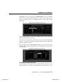
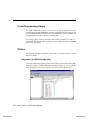
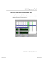
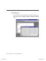
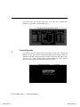
Monitor (for MOXA boards under Windows NT Only)
A useful port status monitoring program allows you to watch the selected MOXA
COM ports’ data transmitting/receiving throughput and communication line status
which are updated and displayed on the screen at every time interval. In addition,
you may click on one of the specific displayed port in order to see the current
communication parameters and status of that port.
Intellio C320Turbo/PCI User's Manual
www.ipc2u.ru
4-3
www.moxa.pro
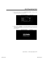
Terminal Emulator
The Terminal Emulator features multi-windows and supports terminal types of
VT100 and ANSI. You can transfer data interactively, send pattern periodically or
transfer file using ASCII, XMODEM, YMODEM, ZMODEM and KERMIT
protocols.
4-4 Intellio C320Turbo/PCI User's Manual
www.ipc2u.ru
www.moxa.pro
Serial Programming Tools
UNIX
Programming the MOXA Ports
The system calls that apply to standard tty port also apply to MOXA port since
MOXA port conforms to UNIX tty standard. System calls are like open(), ioctl(),
read(), write(), close(), etc. Please refer to your UNIX Programmer's Reference
manual.
However, these system services only provide limited functions and thus may not
satisfy the sophisticated programmers’s need. In order to fully control the hardware,
MOXA supports extended services through ioctl() command, which are:
1.
2.
3.
4.
5.
6.
7.
MIBUFED
MOBUFED
MTCRTS
MTCDTR
MLOWATER
MSTATUS
MHWFLOW
(= 0x401)To get byte count in input buffer.
(= 0x402)To get byte count in output buffer.
(= 0x403)To control RTS output signal.
(= 0x404)To control DTR output signal.
(= 0x405)To set output buffer low water level.
(= 0x407)To read modem line status (CTS/DSR/DCD).
(= 0x40e)
To enable/disable the hardware flow control.
The next Section details all the commands.
Extended UNIX Ioctl() Commands
The following describes the syntax and usage of MOXA extended functions for both
non-SVR4.x and SVR4.x UNIX. The variable moxa_fd is the returned file descriptor
by open() a specific MOXA port. For example,
int moxa_fd;
moxa_fd = open("/dev/ttya11",O_RDWR);
1. MIBUFED
This function let you know how many bytes queued in input buffer when this
function is issued.
Syntax for SCO UNIX/XENIX
#define MIBUFED
int
count;
0x401
/*number of bytes queued in the buffer */
ioctl(moxa_fd, MIBUFED, &count);
Intellio C320Turbo/PCI User's Manual
www.ipc2u.ru
4-5
www.moxa.pro
Syntax for UNIX SVR4
#include
#include
#define MIBUFED
struct strioctl
int
count;
<sys/stropts.h>
<sys/sysmacros.h>
0x401
ioc;
/*number of bytes queued in the buffer */
ioc.ic_cmd = MIBUFED;
ioc.ic_timout = 0;
ioc.ic_len = sizeof(int);
ioc.ic_dp = (char *)&count;
ioctl(moxa_fd, I_STR, &ioc);
Note: Due to the characteristics of STREAMS driver, the returned count of bytes buffered
only reflect the data buffered on MOXA board, not including the data buffered in STREAMS
queue. In this case, the count is for reference only. For example, returned count may always
be zero, but there still are data buffered in STREAMS queue.
2. MOBUFED
This function let you know the byte count queued in output buffer when this function
is issued.
Syntax for SCO UNIX/XENIX
#define MOBUFED
int
count;
0x402
/* number of bytes queued in the output buffer */
ioctl(moxa_fd, MOBUFED, &count);
Syntax for UNIX SVR4
#include
#include
#define MOBUFED
struct strioctl
int
count;
<sys/stropts.h>
<sys/sysmacros.h>
0x402
ioc;
/* number of bytes queued in the output buffer */
ioc.ic_cmd = MOBUFED;
ioc.ic_timout = 0;
ioc.ic_len = sizeof(int);
ioc.ic_dp = (char *)&count;
ioctl(moxa_fd, I_STR, &ioc);
Note: See MIBUFED for influence of STREAMS driver.
4-6 Intellio C320Turbo/PCI User's Manual
www.ipc2u.ru
www.moxa.pro
Serial Programming Tools
3. MTCRTS
This function, only valid when hardware flow control is turned off (see
MHWFLOW), is used to turn RTS on or off.
Syntax for SCO UNIX/XENIX
#define MTCRTS
#define TurnON
#define TurnOFF
0x403
1
0
ioctl(moxa_fd, MTCRTS, TurnON);
ioctl(moxa_fd, MTCRTS, TurnOFF);
Syntax for UNIX SVR4
#include
#include
#define MTCRTS
#define TurnON
#define TurnOFF
struct strioctl
int
setting;
<sys/stropts.h>
<sys/sysmacros.h>
0x403
1
0
ioc;
setting = TurnON /* or TurnOFF */;
ioc.ic_cmd = MTCRTS;
ioc.ic_timout = 0;
ioc.ic_len = sizeof(int);
ioc.ic_dp = (char *)&setting;
ioctl(moxa_fd, I_STR, &ioc);
4.
MTCDTR
This function, only valid when hardware flow control is turned off (see
MHWFLOW), is used to turn DTR on or off.
Syntax for SCO UNIX/XENIX
#define MTCDTR
#define TurnON
#define TurnOFF
0x404
1
0
ioctl(moxa_fd, MTCDTR, TurnON);
ioctl(moxa_fd, MTCDTR, TurnOFF);
Intellio C320Turbo/PCI User's Manual
www.ipc2u.ru
4-7
www.moxa.pro
Syntax for UNIX SVR4
#include
#include
#define MTCDTR
#define TurnON
#define TurnOFF
struct strioctl
int
<sys/stropts.h>
<sys/sysmacros.h>
0x404
1
0
ioc;
setting;
setting = TurnON /* or TurnOFF */;
ioc.ic_cmd = MTCDTR;
ioc.ic_timout = 0;
ioc.ic_len = sizeof(int);
ioc.ic_dp = (char *)&setting;
ioctl(moxa_fd, I_STR, &ioc);
5. MLOWATER
Sometimes the application software may not be able to write any further data to the
output buffer because of the output buffer being full. The application has to wait
until the output buffer has 'enough space' again. The criteria to tell if the output
buffer has 'enough space' is that whether the output buffer reached its 'low water'
level. That is the output buffer will accept further data only when the 'low water'
level is reached.
If the 'low water' value is relatively small, you may find that the output buffer
become empty before you write another block of data (this is quite possible because
UNIX is time-sharing multitasking environment). This will result in discontinuous
data transmission. In a timeout-sensitive application, e.g. facsimile (FAX)
transmission, discontinuous data may falter the operation.
The default 'low water' is 512 bytes. You can enlarge it but better not exceed one half
of the output buffer. Each port’s output buffer depends on the number of total ports.
See below.
Model
C320Turbo/PCI
C320Turbo/PCI
C320Turbo/PCI
C320Turbo/PCI
Output buffer/each port
w/8 ports
w/16ports
w/24ports
w/32ports
32K bytes
16K bytes
8K bytes
4K bytes
4-8 Intellio C320Turbo/PCI User's Manual
www.ipc2u.ru
www.moxa.pro
Serial Programming Tools
Syntax for SCO UNIX/XENIX
#define MLOWATER
int
lowater;
0x405
/* low water value of output buffer (default = 512 bytes) */
ioctl(moxa_fd, MLOWATER, lowater);
Syntax for UNIX SVR4
#include
#include
#define MLOWATER
struct strioctl
int lowater;
<sys/stropts.h>
<sys/sysmacros.h>
0x405
ioc;
/* low water value of output buffer (default = 512 bytes) */
ioc.ic_cmd = MLOWATER;
ioc.ic_timout = 0;
ioc.ic_len = sizeof(int);
ioc.ic_dp = (char *)&lowater;
ioctl(moxa_fd, I_STR, &ioc);
6. MSTATUS
This function is used to know the RS-232 line status (CTS/DSR/DCD).
Syntax for SCO UNIX/XENIX
#define MSTATUS
int
status;
0x407
/* status = RS-232 line status*/
/* bit0-CTS (1:on, 0:off)*/
/* bit1-DSR (1:on, 0:off)*/
/* bit2-DCD (1:on, 0:off)*/
ioctl(moxa_fd, MSTATUS, &status);
Syntax for UNIX SVR4
#define MSTATUS
#include
#include
struct strioctl
int
status;
0x407
<sys/stropts.h>
<sys/sysmacros.h>
ioc;
/* status = RS-232 line status*/
/* bit0-CTS (1:on, 0:off)*/
/* bit1-DSR (1:on, 0:off)*/
/* bit2-DCD (1:on, 0:off)*/
ioc.ic_cmd = MSTATUS;
ioc.ic_timout = 0;
ioc.ic_len = sizeof(int);
ioc.ic_dp = (char *)&status;
ioctl(moxa_fd, I_STR, &ioc);
Intellio C320Turbo/PCI User's Manual
www.ipc2u.ru
4-9
www.moxa.pro
7. MHWFLOW
This function is used to enable/disable hardware flow control. The first open()
function of a port will set the hardware flow control bits on or off depending on the
[RTS/CTS Hardware Flow Control] configuration in mxadm. However, you might
want to control the DTR or RTS signal, thus the RTS flow control bit should be
turned off (HWFLowControlOff) in order to take over the control of DTR or RTS
signal via function MTCRTS or MTCDTR. MTCRTS and MTCDTR can be
effective only after the RTS flow control bit is turned off.
Syntax for SCO UNIX/XENIX
#define MHWFLOW
#define HWFlowControlOff
#define CTSFlowControlBitOn
#define RTSFlowControlBitOn
#define HWFlowControlOn
0x40e
0x00
0x01
0x02
0x03
ioctl(moxa_fd, MHWFLOW, CTSFlowControlBitOn);
ioctl(moxa_fd, MHWFLOW, RTSFlowControlBitOn);
ioctl(moxa_fd,MHWFLOW, CTSFlowControlBitOn | RTSFlowControlBitOn);
Syntax for UNIX SVR4
#include
#include
<sys/stropts.h>
<sys/sysmacros.h>
#define MHWFLOW
#define HWFlowControlOff
#define CTSFlowControlBitOn
#define RTSFlowControlBitOn
#define HWFlowControlOn
struct strioctl
int
0x40e
0x00
0x01
0x02
0x03
ioc;
setting;
setting = CTSFlowControlbitOn;
ioc.ic_cmd = MHWFLOW;
ioc.ic_timout = 0;
ioc.ic_len = sizeof(int);
ioc.ic_dp = (char *)&setting;
ioctl(moxa_fd, I_STR, &ioc);
4-10 Intellio C320Turbo/PCI User's Manual
www.ipc2u.ru
www.moxa.pro
Serial Programming Tools
Utilities
You can use the administration utility, mxadm, to monitor port activity and to do
terminal emulation, which are details as follows.
Port Monitoring
This utility gives you a quick view about all the MOXA ports’ activities. You can
easily learn each port’s total received/transmitted (Rx/Tx) character count since the
time when the monitoring is started. Rx/Tx throughputs per second are also reported
in interval basis (e.g. the last 5 seconds) and in average basis (since the time the
monitoring is started). You can reset all ports’ count by <HOME> key. <+> <->
(plus/minus) keys to change the displaying time interval.
Intellio C320Turbo/PCI User's Manual
www.ipc2u.ru
4-11
www.moxa.pro
Press Enter on the port, that the cursor stays, to view the port’s communication
parameters, signal status, and input/output queue.
Terminal Emulator
This utility provides data sending and receiving ability of all tty ports, especially for
MOXA ports. It is quite useful for testing simple application, for example, sending AT
command to a modem connected to the port or used as a terminal for login purpose. Note
that this is only a dumb terminal emulation without handling full screen operation.
Besides, data scope function with pattern/file transfer is provided.
4-12 Intellio C320Turbo/PCI User's Manual
www.ipc2u.ru
www.moxa.pro
Serial Programming Tools
1. Select and Press Enter on item “Communication Setup” to setup up all the
communication parameters for connection.
2. Select and enter “Terminal” to enter terminal emulation. Or select and enter
“Advanced Transfer Modes” to perform pattern or file transfer with protocols
such as ZModem.
Intellio C320Turbo/PCI User's Manual
www.ipc2u.ru
4-13
www.moxa.pro
4-14 Intellio C320Turbo/PCI User's Manual
www.ipc2u.ru
www.moxa.pro
5
5
Connection Option and Cable Wiring
In data communications, the term DTE is Data Terminal Equipment like terminal or
PC COM1/2. The term DCE is Data Communication Equipment like modem. Please
check the precise pinouts, the following pinouts are typical examples.
The UART modules for Desktop option provide both RS-232 and RS-422
connection options, depending on the models of modules you choose. The
Basic/Extensive modules for Rackmount option provide merely RS-232 connection
options. However, all the modules can use together with MOXA A50/A51 to obtain
RS-422/RS-485 capabilities (See MOXA A50/A51 User's Manual for details.)
RS-232 Cable Wiring for C32045T/C32047T/C32071T
The following RS-232 UART Modules are designed for Intellio C320Turbo/PCI.
C32045T : UART Module providing 8 female RS-232 ports.
C32047T : UART Module providing 8 male RS-232 ports.
C32071T : UART Module providing 8 female RS-232 ports with 2000V surge
protection which can protect ports from lightning.
There are two types of connectors, female or male, for RS-232 UART Modules.
You have to identify the type of connectors and apply the correct cable wiring.
Intellio C320Turbo/PCI User's Manual
www.ipc2u.ru
5-1
www.moxa.pro
UART Module C32045T/71T
DB25 Female Connector
2
3
4
5
6
7
8
20
RxD
TxD
CTS
RTS
DTR
GND
DCD
DSR
8
7
6
5
4
3
2
20 DSR
DCD
GND
DTR
RTS
CTS
TxD
RxD
UART Module C32047T
DB25 Male Connector
2
3
4
5
6
7
8
20
Type 1:
TxD
RxD
RTS
CTS
DSR
GND
DCD
DTR
2
3
4
5
6
7
8
20 DTR
TxD
RxD
RTS
CTS
DSR
GND
DCD
Connecting UART Module to a DTE device.
Straight-through Cable
PC COM2 port, Serial Printer,
Terminal, or any DTE Device
C32045T/71T
C32045T/71T
DB25 Female
Connector
RxD
TxD
CTS
RTS
DTR
DSR
GND
DCD
DTE Device
Cable Wiring
2
3
4
5
6
20
7
8
2
3
4
5
6
20
7
8
DB25 Male
Connector
TxD
RxD
RTS
CTS
DSR
DTR
GND
DCD
5-2 Intellio C320Turbo/PCI User's Manual
www.ipc2u.ru
www.moxa.pro
Connection Option and Cable Wiring
Null Modem Cable
PC COM2 port, Serial Printer,
Terminal, or any DTE Device
C32047T
C32047T
DB25 Male
Connector
TxD
RxD
RTS
CTS
DSR
DTR
GND
DCD
DTE Device
Cable Wiring
2
3
4
5
6
20
7
8
2
3
4
5
6
20
7
8
PC COM2 port, Serial Printer,
Terminal, or any DTE Device
C32047T
C32047T
DB25 Male
Connector
TxD
RxD
RTS
CTS
DSR
DTR
GND
DCD
DB25 Male
Connector
TxD
RxD
RTS
CTS
DSR
DTR
GND
DCD
DTE Device
Cable Wiring
2
3
4
5
6
20
7
8
2
3
8
7
4
6
5
1
DB9 Male
Connector
RxD
TxD
CTS
RTS
DTR
DSR
GND
DCD
Intellio C320Turbo/PCI User's Manual
www.ipc2u.ru
5-3
www.moxa.pro
Type 2:
Connecting UART Module to a DCE device.
Null Modem Cable
Modem,
or any DCE Device
C32045T/71T
C32045T/71T
DB25 Female
Connector
RxD
TxD
CTS
RTS
DTR
DSR
GND
DCD
DCE Device
Cable Wiring
2
3
4
5
6
20
7
8
2
3
4
5
6
20
7
8
DB25 Female
Connector
RxD
TxD
CTS
RTS
DTR
DSR
GND
DCD
Straight-through Cable
Modem,
or any DCE Device
C32071T
C32071T
DB25 Male
Connector
TxD
RxD
RTS
CTS
DSR
DTR
GND
DCD
DCE Device
Cable Wiring
2
3
4
5
6
20
7
8
2
3
4
5
6
20
7
8
DB25 Female
Connector
RxD
TxD
CTS
RTS
DTR
DSR
GND
DCD
5-4 Intellio C320Turbo/PCI User's Manual
www.ipc2u.ru
www.moxa.pro
Connection Option and Cable Wiring
Type 3:
Connecting UART Module to a DTE device with 3-pin wiring.
If the“Hardware flow control” feature is set to “ON”, you must loop
back (or short) the RTS with CTS and DSR with DTR, DCD on MOXA
site, indicated in dash-lines of the following diagrams. If the“Hardware
flow control” feature is set to “OFF”, you could just leave RTS, CTS,
DSR, DTR, DCD open, ignoring the connection indicated in dash-lines.
PC COM2 port, Serial Printer,
Terminal, or any DTE Device
C32045T/71T
C32045T/71T
DB25 Female
Connector
RxD
TxD
GND
CTS
RTS
DTR
DSR
DCD
DTE Device
Cable Wiring
2
3
7
4
5
6
20
8
2
3
7
4
5
6
20
8
PC COM2 port, Serial Printer,
Terminal, or any DTE Device
C32047T
C32047T
DB25 Male
Connector
TxD
RxD
GND
RTS
CTS
DSR
DTR
DCD
DB25 Male
Connector
TxD
RxD
GND
RTS
CTS
DSR
DTR
DCD
DTE Device
Cable Wiring
2
3
7
4
5
6
20
8
2
3
7
4
5
6
20
8
DB25 Male
Connector
TxD
RxD
GND
RTS
CTS
DSR
DTR
DCD
Intellio C320Turbo/PCI User's Manual
www.ipc2u.ru
5-5
www.moxa.pro
PC COM2 port, Serial Printer,
Terminal, or any DTE Device
C32047T
C32047T
DB25 Male
Connector
TxD
RxD
GND
RTS
CTS
DSR
DTR
DCD
DTE Device
Cable Wiring
2
3
7
4
5
6
20
8
2
3
5
7
8
4
6
1
DB9 Male
Connector
RxD
TxD
GND
RTS
CTS
DTR
DSR
DCD
5-6 Intellio C320Turbo/PCI User's Manual
www.ipc2u.ru
www.moxa.pro
Connection Option and Cable Wiring
RS-422 Cable Wiring for C32061T/C32065T
The following RS-422 UART Modules are designed for Intellio C320Turbo/PCI.
C32061T:
C32065T:
UART Module providing 8 female RS-422 DB25 ports without
isolation protection.
UART Module providing 8 female RS-422 DB25 ports with 2000V
isolation protection which can prevent damage caused by high
potential voltage.
13 RTS-(A)
C32061T/65T
2
3
14
16
7
4
5
13
19
☞
RxD+(B)
TxD+(B)
RxD-(A)
TxD-(A)
GND
CTS+(B)
RTS+(B)
RTS-(A)
CTS-(A)
CTS-(A) 19
7 GND
TxD-(A) 16
5
4
3
2
RxD-(A) 14
RTS+(B)
CTS+(B)
TxD+(B)
RxD+(B)
The DTR, DSR and DCD signal lines (not shown) of the
C32061T/C32065T are internally shorted by design to meet certain
software requirements.
The RS-422 transmission distance can reach as long as 4000ft. The connection box
needs an external power adapter to supply 5V DC power. Either 110V or 220V AC
power adapter is selectable.
Intellio C320Turbo/PCI User's Manual
www.ipc2u.ru
5-7
www.moxa.pro
The followings are operation modes for RS-422:
RS-422 Point-to-point
C32061T/65T
3 TxD+(B)
16 TxD-(A)
2 RxD+(B)
14 RxD-(A)
7 GND
RS-422 Device
RxD+(B)
RxD-(A)
TxD+(B)
TxD-(A)
GND
RS-422 Broadcasting
C32061T/65T
TxD+(B)
RxD+(B)
TxD-(A)
RxD-(A)
GND
RS-422 Device 1
RxD+(B)
TxD+(B)
RxD-(A)
TxD-(A)
GND
RS-422 Device N
RxD+(B)
TxD+(B)
RxD-(A)
TxD-(A)
GND
RS-422 with Handshaking
C32061T/65T
3 TxD+(B)
16 TxD-(A)
2 RxD+(B)
14 RxD-(A)
7 GND
5 RTS+(B)
13 RTS-(A)
4 CTS+(B)
19 CTS-(A)
RS-422 Device
RxD+(B)
RxD-(A)
TxD+(B)
TxD-(A)
GND
CTS+(B)
CTS-(A)
RTS+(B)
RTS-(A)
5-8 Intellio C320Turbo/PCI User's Manual
www.ipc2u.ru
www.moxa.pro
Connection Option and Cable Wiring
RS-422 Impedance Matching
When an electrical signal travels through two different resistance junctions in a
transmission line, the mismatch will sometimes cause signal reflection. Signal
reflection causes signal distortion, which in turn will contribute communication
errors. The solution to this problem is to establish the same impedance at the line
ends as in the line itself by terminating them with resistors.
It is normally sufficient when the value of the termination resistor equals the
characteristic impedance of the transmission line. The resistors should be added near
the receiving side. See below.
C32061T/65T
3
16
2
14
5
13
4
19
TxD+(B)
TxD-(A)
RxD+(B)
RxD-(A)
RTS+(B)
RTS-(A)
CTS+(B)
CTS-(A)
Remote site
RxD+(B)
RxD-(A)
TxD+(B)
TxD-(A)
CTS+(B)
CTS-(A)
RTS+(B)
RTS-(A)
Note:
1. stands for termination resistor near the receiving side.
2. The suggested termination resistor for AWG #26 cable is 100 ohm.
3. The suggested termination resistor for phone cable is 600 ohm.
Intellio C320Turbo/PCI User's Manual
www.ipc2u.ru
5-9
www.moxa.pro
RS-232 Cable Wiring for C32080T/81T/82T/83T & CN20040
For Basic/Extensive Modules, only RS-232 interface with RJ-45 female connector is
supported. A 1.5-meter male RJ-45 to male DB25 RS-232 testing cable, CN20040,
is provided with shipment of the Basic Module.
The following RS-232 Basic Modules are designed for Intellio C320Turbo/PCI.
C32080T : Basic Module providing 8 female RS-232 ports.
C32081T : Basic Module providing 16 female RS-232 ports.
The following RS-232
C320Turbo/PCI.
Extensive
Modules
are
designed
for
Intellio
C32082T : Extensive Module providing 8 female RS-232 ports.
C32083T : Extensive Module providing 16 female RS-232 ports.
C32080T/81T/82T/83T RJ-45 Jack
Pin
Signals
1
1
2
3
4
5
6
7
8
9
10
DCD
DSR
RTS
GND
TxD
RxD
GND
CTS
DTR
-
10
RJ45 JACK
5-10 Intellio C320Turbo/PCI User's Manual
www.ipc2u.ru
www.moxa.pro
Connection Option and Cable Wiring
Type 1:
Connecting Basic/Extensive Module to a DTE device.
CN20030
PC COM2 port, Serial Printer,
Terminal, or any DTE Device
C3208xT
RJ45 Plug Pin 1
C3208xT
RJ45 Jack
Connector
DCD
DSR
RTS
GND
TxD
RxD
CTS
DTR
☞
☞
DTE Device
Cable Wiring
1
2
3
4/7
5
6
8
9
8
20
5
7
3
2
4
6
DB25 Male
Connector
DCD
DTR
CTS
GND
RxD
TxD
RTS
DSR
For Rackmount option, this RJ45 to female DB25 RS-232 testing cable
(CN20030) is available from Moxa.
4/7 means either line 4 or line 7 can be used for GND.
PC COM2 port, serial printer,
terminal, or any DTE device
C3208xT
RJ45 Plug Pin 1
C3208xT
RJ45 Jack
Connector
DCD
DSR
RTS
GND
TxD
RxD
CTS
DTR
☞
DTE Device
Cable Wiring
1
2
3
4/7
5
6
8
9
1
4
8
5
2
3
7
6
DB9 Male
Connector
DCD
DTR
CTS
GND
RxD
TxD
RTS
DSR
4/7 means either line 4 or line 7 can be used for GND.
Intellio C320Turbo/PCI User's Manual
www.ipc2u.ru
5-11
www.moxa.pro
Type 2:
Connecting Basic/Extensive Module to a DCE device.
Cable CN20040
Modem,
or any DCE Device
C3208xT
RJ45 Plug Pin 1
C3208xT
RJ45 Jack
Connector
DCD
DSR
RTS
GND
TxD
RxD
CTS
DTR
☞
☞
DCE Device
Cable Wiring
1
2
3
4/7
5
6
8
9
8
6
4
7
2
3
5
20
DB25 Female
Connector
DCD
DTR
CTS
GND
RxD
TxD
RTS
DSR
For Rackmount option, this RJ45 to male DB25 RS-232 testing cable
(CN20040) comes with the Basic Module and is provided for testing.
4/7 means either line 4 or line 7 can be used for GND.
5-12 Intellio C320Turbo/PCI User's Manual
www.ipc2u.ru
www.moxa.pro
Connection Option and Cable Wiring
Type 3:
Connecting Basic/Extensive Module to a DTE device with 3-pin
wiring.
If the“Hardware flow control” feature is set to “ON”, you must loop
back (or short) the RTS with CTS and DSR with DTR, DCD on MOXA
site, indicated in dash-lines of the following diagrams. If the“Hardware
flow control” feature is set to “OFF”, you could just leave RTS, CTS,
DSR, DTR, DCD open, ignoring the connection indicated in dash-lines.
PC COM2 port, Serial Printer,
Terminal, or any DTE Device
C3208xT
RJ45 Plug Pin 1
C3208xT
RJ45 Jack
Connector
TxD
RxD
GND
RTS
CTS
DTR
DSR
DCD
☞
DTE Device
Cable Wiring
5
6
4/7
3
8
9
2
1
3
2
7
5
4
6
20
8
DB25 Male
Connector
RxD
TxD
GND
CTS
RTS
DSR
DTR
DCD
4/7 means either line 4 or line 7 can be used for GND.
PC COM2 port, Serial Printer,
Terminal, or any DTE Device
C3208xT
RJ45 Plug Pin 1
C3208xT
RJ45 Jack
Connector
TxD
RxD
GND
RTS
CTS
DTR
DSR
DCD
☞
DTE Device
Cable Wiring
5
6
4/7
3
8
9
2
1
2
3
5
8
7
6
4
1
DB9 Male
Connector
RxD
TxD
GND
CTS
RTS
DSR
DTR
DCD
4/7 means either line 4 or line 7 can be used for GND.
Intellio C320Turbo/PCI User's Manual
www.ipc2u.ru
5-13
www.moxa.pro
C32020T Link Cable
There are two different types of link cables: 25-signal-pin link cable and 10-signalpin link cable. The former is used when there is no external power applied to the
external module (CPU/Basic Module). The latter is used when the external power is
applied to the external module (CPU/Basic Module) if you have chosen to use Long
Rang Extension Kit.
25-signal-pin Link Cable (standard)
The factory-supplied 2-meter link cable (the one with 25 signal pins) is used only
when you are NOT using the external power adapter. Pin assignments are given
below for this 25-pin link cable.
Warning!
Do not use the factory-supplied 2-meter link cable (with 25 signal
pins) and the external power adapter at the same time, otherwise the
Control Board or CPU/Basic Module may be seriously damaged.
Pin No. Signal
1
2
3
4
5
6
7
8
9
10
11
12
13
GND
DX+
DR+
GND
GND
GND
-12V
+5V
+5V
+5V
CLK+
FSRDX-
Pin No. Signal
14
15
16
17
18
19
20
21
22
23
24
25
CLKFSX+
FSR+
GND
GND
GND
+12V
+5V
+5V
+5V
FSXDR-
5-14 Intellio C320Turbo/PCI User's Manual
www.ipc2u.ru
www.moxa.pro
Connection Option and Cable Wiring
10-signal-pin Link Cable (for long range extension only)
If the external power adapter is applied to the CPU/Basic Module, you will need to
use the 10-pin cable accompanying with the Long Range Extension Kit. The Control
Board to CPU/Basic Module should have only 10 signal pins with the following
pinouts.
Warning!
Make the link cable carefully and precisely according to the
following pinout, otherwise you will risk damaging the Control
Board and CPU/Basic Module.
Pin No. Signal
2
3
11
12
13
☞
DX+
DR+
CLK+
FSRDX-
Pin No. Signal
14
15
16
24
25
CLKFSX+
FSR+
FSXDR-
You can connect the existing 10-signal-pin cable to a 25-signal-pin cable
to form a longer 2-segment cable to extend the connection distance up to
100 meters (328 ft).
Intellio C320Turbo/PCI User's Manual
www.ipc2u.ru
5-15
www.moxa.pro
5-16 Intellio C320Turbo/PCI User's Manual
www.ipc2u.ru
www.moxa.pro
6
Troubleshooting
6
General Troubleshooting
Common Intellio C320Turbo/PCI problems and possible solutions are listed below,
in addition to those operating systems specific ones. If you still have problems,
contact your dealer or Moxa for help. Or report it using “Problem Report Form” at
the end of this manual to your dealer at once for technical support.
1. MOXA PCI board can not be detected by the MOXA driver while installing
the driver.
Hardware causes and solutions:
a. The board is not installed or missing (absent). Please install it.
b. The board is not properly plugged in the system. If that is the case, then reinstall the board and make sure that it fits well in a 32-bit PCI slot this time.
Sometimes the slot for plugging board is bad. In this case, please try other
slots until a good one is found.
c. Your mother board does not have vacant IRQ for the Intellio
C320Turbo/PCI. Please enter BIOS and make sure there are available IRQ
in PCI/PnP setting.
2. MOXA board and driver
(transmitting/receiving) data.
activated
but
can
not
transfer
Hardware Causes and Solutions:
a. Check if wrong cable wiring. Refer to the “Connection Option and Cable
Wiring” chapter for precise pinouts of the connector type you are using.
b. Cable, external modules or board is defective. You may use other port, cable
Intellio C320Turbo/PCI User's Manual
www.ipc2u.ru
6-1
www.moxa.pro
or box or board to verify. In addition, PComm utility “Diagnostic” for
Windows NT and Windows 95/98 is good for testing MOXA board and port
condition. If the report of diagnostic shows error, replace the error
component.
Software Causes and Solutions:
a. Intellio C320Turbo Series will check line status (CTS) before it sends data
out if RTS/CTS flow control feature is set to “Enable” in configuration or
application program. Please see the “Connection Options and Cable
Wiring” chapter for proper wiring. Check the line status of the suspected
port using the diagnostic LED indicators on the mini tester.
b. Perhaps the application controlling the board is not correctly written
according to the corresponding API of the operating system. To verify,
please run existing and known good application or Moxa provided utility.
For example, under Windows NT and Windows 95/98, PComm utility
“Terminal emulator” or “Hyperterminal” is good for testing COM ports.
Under UNIX, “Terminal emulator” in the MOXA administration utility
“mxadm” and “stty”, “cat”, or “getty” are existed programs for testing tty
port.
3. “CPU/Basic Module not found” message appears. Or CPU/Basic Module
can not download firmware from the Control Board.
Hardware Causes and Solutions:
a. Switch off the CPU/Basic Module. Check that the connection cable between
the CPU/Basic Module and the Control Board is correct and firmly
connected on both sides. Switch on the CPU/Basic Module, then power on
the Control Board system to wait until the LED display of CPU/Basic
Module reads “Ld”.
b. Sometimes it happens when the total consumption of power in the system is
higher than the power adapter can provide. Especially when many interface
boards including MOXA board(s) are plugged in the system. It is
recommended to replace the current power adapter with higher watt one. Or
choose the external power option if Intellio C320Turbo/PCI is used.
c. If all the possible methods fail, the CPU/Basic Modules might be defective.
Please check the module(s) one at a time in the system to find out the defective one.
6-2 Intellio C320Turbo/PCI User's Manual
www.ipc2u.ru
www.moxa.pro
Troubleshooting
4. Error messages appear on CPU/Basic Module LED display.
Any of the following messages means failure of the Intellio C320Turbo/PCI
initialization.
E0:
E1:
E2:
E4:
E5:
A1:
A2:
10:
20:
30:
40:
CPU/Basic Module ROM error.
CPU/Basic Module RAM error.
No UART Module present.
The power to the CPU/Basic Module has been switched off and on swiftly,
or some Module is missing during the power-off time.
The connection between Modules is loose or broken.
CPU/Basic Module execution failure.
CPU/Basic Module can not communicate with Control Board.
The first UART Module initialization failure.
The second UART Module initialization failure.
The third UART Module initialization failure.
The forth UART Module initialization failure.
Hardware Causes and Solutions:
If the error message persists after check, return the unit for repair.
As “E0”, “E1” or “A1” occurs, usually you have to turn off and on the CPU
Module. If problem persists, the CPU Module might be defective.
As “E2” occurs, turn off the CPU Module, firmly connect the UART Modules,
and turn the power back on.
As “E4” occurs, usually you have to turn off the CPU/Basic Module, then turn on
at least time interval 3 seconds. Or check if the total number of ports (or
modules) is correct or not.
As “E5” occurs, it may indicates that the cables between modules should be
fastened carefully.
As “A2” occurs, check the link between CPU Module and Control Board is
fastened carefully.
As “10”, “20”, “30” or “40” occurs, make sure the connection between modules is
proper.
Intellio C320Turbo/PCI User's Manual
www.ipc2u.ru
6-3
www.moxa.pro
5. Upon system startup or driver initialization, the “Number of ports
mismatch” message appears.
Hardware Causes and Solutions:
The total number of ports installed is less than that of configured.
a.
Shut off the system and check all modules and their connections. Make sure
that all the module(s) is(are) fastened properly.
b.
Run the board configuration program to check the board configuration. For
Intellio C320Turbo/PCI, connect the CPU/Basic Module with proper
number of UART/Extensive Module(s) as configured in configuration
program.
c.
If all the possible methods fail, one of the module(s) might be defective.
Please check the module(s) one at a time in the system to find out the
defective one.
6-4 Intellio C320Turbo/PCI User's Manual
www.ipc2u.ru
www.moxa.pro
Troubleshooting
Windows NT
This section is specific for troubleshooting under Windows NT. For general
problems and solutions, please see the previous section, “General Troubleshooting”.
1. After system starts, error message “MOXA C320Turbo/PCI Multiport
Board #1 addr(XXX): CPU/Basic Module not found!” appears in Event
Log.
Shutdown the system first and refer to the problem 3 for solutions in the previous
section, “General Troubleshooting”.
2. After system starts, error message “MOXA C320Turbo/PCI Multiport
Board #1 addr(XXX): number of UART Modules mismatch!” appears in
Event Log.
Make sure that all the modules are fastened properly. Or open [Control Panel],
select the [Network] icon, [Adapters] tab, and select “MOXA Intellio
C320Turbo Series Adapter” item in the “Installed Adapter Cards:” and click on
the [Properties...] button to start the “MOXA Configuration Panel” dialog box,
and make sure to connect the CPU Module with proper number of UART
Module(s) as configured.
3. After system starts, error message “MOXA C320Turbo/PCI Multiport
Board #1 addr(XXX): number of ports mismatch!” appears in Event Log.
Make sure that all the module(s) is(are) fastened properly and the ports installed
are the same as configured. Or open [Control Panel], select [Network] icon,
then [Adapters] tab, select “MOXA Intellio C320Turbo Series Adapter” item
in the “Installed Adapter Cards:” and click on the [Properties...] button to start
the “MOXA Configuration Panel” dialog box, and make sure to connect the CPU
Module with proper number of UART Module(s) as configured.
4. After system starts, error message “MOXA C320Turbo/PCI Multiport
Board #1 addr(XXX): IRQ test failure!” appears in Event Log.
This indicates MOXA board is found but the IRQ is conflicting with other
adapter. Please make sure there is no conflict with other adapter's IRQ. Check the
PCI BIOS IRQ setting first. Make sure IRQ is available.
Intellio C320Turbo/PCI User's Manual
www.ipc2u.ru
6-5
www.moxa.pro
5. After system starts, error message “MOXA C320Turbo Multiport Board #1
addr(XXX): CPU/Basic module download failure!” appears in Event Log.
Shutdown the system first and refer to the problem 3 for solutions in the previous
section, “General Troubleshooting”.
6. Windows NT system panic (blue screen).
The possible reason is IRQ conflict with other ISA Bus adapters like LAN and
SCSI board, RAID controller or system BIOS.
7. Error message “C320tnt.cod file not found!” appears.
Error message “C320tnt.cod file length is wrong!” appears.
Error message “C320tnt.cod file data content error!” appears.
It means something is wrong with driver installation or the file has been deleted
accidentally or corrupted somehow. To recover, simply reinstall the driver.
6-6 Intellio C320Turbo/PCI User's Manual
www.ipc2u.ru
www.moxa.pro
Troubleshooting
Windows 95/98
This section is specific for troubleshooting under Windows 95/98. For general
problems and solutions, please see the previous section, “General Troubleshooting”.
1. Error message “MOXA C320Turbo/PCI (BusNo=xx, DevNo=xx) at base
memory [XXX] download failure!” appears.
Shutdown the system first and refer to the problem 3 for solutions in the previous
section, “General Troubleshooting”.
2. Error message “MOXA C320Turbo/PCI (BusNo=xx, DevNo=xx) at base
memory [XXX] number of UART Modules mismatch!” appears.
Make sure that all the module(s) is(are) fastened properly. Or click on the
Taskbar [Start] button, [Programs] menu, [MOXA Utilities] menu, [MOXA
Configuration Panel] icon, and connect the CPU Module with proper number of
UART Module(s) as configured.
3. Error message “MOXA C320Turbo/PCI (BusNo=xx, DevNo=xx) at base
memory [XXX] ports number mismatch!” appears.
Make sure that all the Module(s) is(are) fastened properly and the ports installed
are the same as configured. Or click on the Taskbar [Start] button, [Programs]
menu, [MOXA Utilities] menu and [MOXA Configuration Panel] icon, and
connect the Basic Module with proper number of Extensive Module(s) as
configured.
4. Error message “MOXA C320Turbo/PCI (BusNo=xx, DevNo=xx) at base
memory [XXX] CPU/Basic Module not found!” appears.
Shutdown the system first and refer to the problem 3 for solutions in the previous
section, “General Troubleshooting”.
5. Error message “MOXA C320Turbo/PCI (BusNo=xx, DevNo=xx) at base
memory [XXX] CPU/Basic Module download failure!” appears.
Shutdown the system first and refer to the problem 3 for solutions in the previous
section, “General Troubleshooting”.
Intellio C320Turbo/PCI User's Manual
www.ipc2u.ru
6-7
www.moxa.pro
6. Error message “C320Turbo/PCI (BusNo=xx, DevNo=xx) at base memory
[XXX] interrupt failure!” appears.
This indicates MOXA board is found but the IRQ is conflicting with other
adapter. Make sure there is no conflict with other adapter's IRQ. Check the PCI
BIOS IRQ setting and make sure IRQ is available.
7. Error message “C320twin.cod file not found!” appears.
Error message “C320twin.cod file length is wrong!” appears.
Error message “C320twin.cod file data content error!” appears.
It means something is wrong with driver installation or the file has been deleted
accidentally or corrupted somehow. To recover, simply reinstall the driver.
UNIX
This section is specific for troubleshooting under UNIX. For general problems and
solutions, please see the previous “General Troubleshooting” section.
1. During system reboots, error message “WARNING! C320Turbo/PCI
(XX000;BusNo=X;DevNo=X) not found!” appears.
The possible cause is memory conflict or defective board. Please shutdown the
system first, and then refer to the problem 1 for solutions in the previous
“General Troubleshooting” section.
2. During system reboots, error message “ERROR! C320Turbo/PCI (XX000;
BusNo=X;DevNo=X) download failed!” appears.
The possible cause is memory conflict or defective board. Please shutdown the
system first, and then refer to the problem 1 for solutions in the previous
“General Troubleshooting” section.
3. MOXA port responds too slowly or abnormal key operation.
The applications are not compatible with the Intellio C320Turbo/PCI On-board
line discipline. The only way to work it around is to set On-board line discipline
feature to “Disable” in [Board] sub-menu of Advanced configuration (the
“UNIX” section of the “Software Installation” chapter).
6-8 Intellio C320Turbo/PCI User's Manual
www.ipc2u.ru
www.moxa.pro
Troubleshooting
4. When respawning quite a few number of tty ports, the following error
messages appear: “Time out table overflow”, “File table overflow”, “Region
table overflow”.
The above error messages imply that the system resources are exhausted. You
should tune the kernel parameters to a larger value and rebuild the kernel to be
able to accommodate the new configuration. Refer to UNIX system manual about
how to tune the parameters and rebuild kernel.
“Time out table overflow” :NCALL parameter too small.
“File table overflow”
:NFILE or NINODE parameter too small.
“Region table overflow”
:NREGION or NPROC parameter too small.
5. The newly rebuilt kernel could not boot.
The Intellio C320Turbo/PCI driver might not be built into the new kernel
correctly.
a. Please use the last good kernel backup to boot again. The kernel backup in
SCO UNIX is /unix.moxa while in UNIX SVR4.2 /stand/unix.moxa.
b. Then remove the Intellio C320Turbo/PCI driver. Refer to “UNIX” section
of “Software Installation” chapter for driver removal.
c. Re-install the Intellio C320Turbo/PCI driver once more.
6. When using MOXA port for PPP/SLIP connection, what should the “On
Board Line Discipline” feature be set to?
Set to “Disable”. Otherwise the PPP/SLIP connection will fail.
Intellio C320Turbo/PCI User's Manual
www.ipc2u.ru
6-9
www.moxa.pro
6-10 Intellio C320Turbo/PCI User's Manual
www.ipc2u.ru
www.moxa.pro
Ap p e n d i x
A Technical Reference
Specifications
System
Up to 32 serial ports per Control Board
Up to 4 Control Boards per PC system for a total of 128 ports
Supports device drivers for most popular operating systems. See the driver
support list below:
C320Turbo/PCI
Windows NT
Windows 95/98
SCO UNIX/OpenServer
UNIX SVR4.2
XENIX
Linux2.0.x/2.2.x
✓
✓
✓
✓
✓
R
✓:
Driver supported by Moxa and shipped with product
R : By request
Note: Download the newest drivers from the MOXA FTP service
Control Board
57 MHz TMS320BC52 processor
512 KB dual-ported RAM, maps to 16K Bytes system RAM
Base addresses from 1M to 4G
Selectable IRQ: 2 (or 9), 3, 4, 5, 7, 10, 11, 12, or 15
Half-size board, ASIC and SMT design
CPU/Basic Module can be located up to 100 m (328 ft) away from the host
computer
100 m
To CPU/Basic Module
C320
Turbo/PCI
Intellio C320Turbo/PCI
www.ipc2u.ru
A-1
www.moxa.pro
CPU Module and UART Module for Desktop Option
CPU Module (for Desktop option)
40 MHz TMS320C52 processor
16 KB ROM and 32 K Words RAM
Diagnostic LEDs show full status of each serial port, including TxD, RxD, DTR,
DSR, RTS, CTS, DCD
Optional power adapter for use when the distance between Control Board and
CPU Module is longer than 2 meters. In this case, a 10-signal-pin DB25 to DB25
cable must be used between Control Board and CPU Module.
Power switch
FCC Class A
CPU Module Front View
To UART Module
To Control Board
Module Side View
ON OFF
DC IN
UART Module (for Desktop option)
8 RS-232/RS-422 serial ports
TI550C UART chip with 32 bytes FIFO (Tx+Rx) and on-chip hardware flow
control
Each UART chip drives one serial port (Max. 460.8 Kbps)
Up to 4 (at least one) modules can be connected to one Control Board
RS-232 (DB25 female/male connectors) : TxD, RxD, RTS, CTS, DTR, DSR,
DCD, GND (Full modem control signals)
RS-422 (DB25 female connectors) : TxD+/-, RxD+/-, CTS+/-, RTS+/-, GND
Fixing Kit with 2 metal plates and 4 screws
FCC Class A
A-2 Intellio C320Turbo/PCI
www.ipc2u.ru
www.moxa.pro
Technical Reference
1
2
3
4
5
6
7
8
UART Module
Basic Module and Extensive Module for Rackmount Option
Basic Module (for Rackmount option)
8 or 16 serial ports
40MHz TMS320C52 processor
16KB ROM and 32K Words RAM
Diagnostics LEDs show full status of each serial port, including TxD, RxD,
DTR, DSR, RTS, CTS, DCD
16550C UART chip with 32 bytes FIFO (Tx+Rx) and on-chip hardware flow
control
Each UART chip drives one serial port (Max. 460.8K bps)
Full modem control (RS-232 interface)
RJ-45 connector for each serial port
Optional power adapter for use when the distance between Control Board and
Basic Module is longer than 2 meters. In this case, a 10-signal-pin DB25 to
DB25 cable must be used between Control Board and Basic Module.
Power switch
Intellio C320Turbo/PCI
www.ipc2u.ru
A-3
www.moxa.pro
Basic Module ( Front View )
Multiport Controller
B?a?s?i?c
M?o?d?u?l?e
Power TxD
RxD
DTR
DSR
RTS
CTS
DCD
Module Channel
Basic Module ( Rear View )
P9
P16
P1
P8
To next module
From PC
DC IN
ON/OFF
To Control Board
Extensive Module (for Rackmount option)
❖ 8 or 16 RS-232 serial ports
❖ 16550C UART chip with 32 bytes FIFO (Tx+Rx) and on-chip hardware flow
control
❖ Each UART chip drives one serial port (Max. 460.8 Kbps)
❖ Full modem control (RS-232 interface)
❖ RJ-45 connector for each serial port
Extensive Module ( Front View)
Multiport Controlle r
E‧x‧t ‧e ‧n‧s ‧i‧v‧e
M‧o ‧d ‧u‧l‧e
Power
P9
P16
P1
P8
To next module
From previous module
A-4 Intellio C320Turbo/PCI
www.ipc2u.ru
www.moxa.pro
Technical Reference
PCI
The 32-bit Intellio C320Turbo/PCI board complies with PCI Spec. 2.1. Hardware
configuration for IRQ and Memory addresses is automatically assigned by PCI
BIOS. Hence, it is a must to have the board plugged first before installing software
driver.
Unlike ISA slots, different PCI slots in the same PC may have different bus numbers
and device numbers with respect to PCI specifications. The same PCI board will
have different system configurations if switched to a different PCI slot, which may
be called slot-sensitive or slot-dependent. This may also apply to PCI slots in PC of
different mother board, which may use different device number set. For example,
some use 17, 18, 19, and 20 for identifying the respective PCI slot but some use 11,
12, 13 and 14.
Due to the slot-dependency, it is necessary to re-configure the software driver
once the board is plugged in different PCI slots.
Up to four boards of Intellio C320Turbo/PCI are allowed in a system. When
installing multiple boards, please do keep in mind the order you plug the boards
for distinguishing the boards installed.
Dual-Ported RAM
There is 512 KB of dual-ported DRAM on the Intellio C320Turbo/PCI Control
Board, which is used as a data buffer and memory map device for the motherboard.
it is called “dual-ported” because it is accessed by both motherboard CPU and the
Intellio C320Turbo/PCI Control Board’s on-board CPU. Generally speaking, the
memory access time is much faster than normal I/O access.
All messages and data are transferred through this 512 KB dual-ported memory. The
buffer area appears as normal 16-bit memory to the PC AT I/O channel.
Every Intellio C320Turbo/PCI Control Board only occupies 16 KB of memory
space (window) from the system point of view. Memory base addresses range from 1
M to 4 GB.
Intellio C320Turbo/PCI
www.ipc2u.ru
A-5
www.moxa.pro
16550C in UART/Basic/Extensive Modules
The 16550C is an advanced asynchronous controller capable of on-chip hardware
flow control and highest speed up to 921.6 Kbps. Inside UART/Basic/Extensive
Module, each 16550C chip controls one port.
A-6 Intellio C320Turbo/PCI
www.ipc2u.ru
www.moxa.pro