1
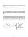
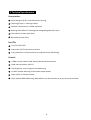
Order Ref: ISIM31 -‐ User Manual Please read the instructions carefully before use CONTENTS 1. Safety Instruction ..................................................................................................... 2 2. Technical Specifications ........................................................................................... 4 3. How To Set The Unit ................................................................................................ 6 3.1 Rear Panel .......................................................................................................... 6 3.2 Main Function .................................................................................................... 7 3.3 Home Position Adjustment .............................................................................. 15 4. How to Control the Unit ........................................................................................ 16 4.1 Master/Slave Built In Preprogrammed Function ............................................. 16 4.2 Easy Controller ................................................................................................. 17 4.3 DMX Controller ................................................................................................ 17 5. DMX512 Configuration .......................................................................................... 18 6. DMX Connection .................................................................................................... 20 7. Troubleshooting ..................................................................................................... 21 8. Fixture Cleaning ..................................................................................................... 22 1 1. Safety Instruction WARNING Please read carefully the instruction, which includes important information about the installation, usage and maintenance. Please keep this User Guide for future consultation. If you sell the unit to another user, be sure that they also receive this instruction manual. Unpack and check carefully there is no transportation damage before using the unit. Before operating, ensure that the voltage and frequency of power supply match the power requirements of the unit. It’s important to ground the yellow/green conductor to earth in order to avoid electric shock. The unit is for indoor use only. Use only in a dry location. The unit must be installed in a location with adequate ventilation, at least 50cm from adjacent surfaces. Be sure that no ventilation slots are blocked. Disconnect mains power before replacement or servicing. Make sure there are no flammable materials close to the unit while operating as it is a fire hazard. Use a safety cable when mounting this unit. DO NOT handle the unit by taking its head only, but always by taking its base. Maximum ambient temperature is Ta: 40°. DO NOT operate it where the temperature is higher than this. Unit surface temperature may reach up to 85°. DO NOT touch the housing bare-‐hand during its operation. Turn off the power and allow about 15 minutes for the unit to cool down before replacing or servicing. In the event of a serious operating problem, stop using the unit immediately. Never try to repair the unit by yourself. Repairs carried out by unskilled people can lead to damage or malfunction. Please contact the nearest authorised technical assistance center. Always use the same type spare parts. DO NOT touch any wire during operation as high voltage might cause electric shock. 2 Warning To prevent or reduce the risk of electrical shock or fire, do not expose the unit to rain or moisture. DO NOT open the unit within fifteen minutes after switching off. The housing, the lenses, or the ultraviolet filter must be replaced if they are visibly damaged. Caution There are no user serviceable parts inside the unit. DO NOT open the housing or attempt any repairs yourself. In the unlikely event your unit may require service, please contact your nearest dealer. Installation The unit should be mounted via omega bracket (see below). Always ensure that the unit is firmly fixed to avoid vibration and slipping while operating. And make sure that the structure to which you are attaching the unit is secure and is able to support a weight of 10 times of the unit’s weight. Also always use a safety cable that can hold 12 times of the weight of the unit when installing the fixture. Professionals must fit the equipment. It must be fixed at a place where is out of reach and has no one passing by or under it. 3 2. Technical Specifications Construction: Stylish design with fire retardant plastic housing Fastening System: 2 x Omega clamps Excellent ventilation for reliable operation Rotating Gobo Wheel: 6 rotating and changeable gobos plus open Color Wheel: 8 colors plus white Adjustable manual focus Pan/Tilt: Pan/Tilt: 540°/270° Automatic Pan/Tilt position correction Easy calibration and maintenance by magnetic home positioning Control: 3 DMX control modes: DMX, Master/Slave and Sound Active DMX channel modes: 8/11CH LED display for easy navigation and addressing 0~100% smooth dimming and variable strobe speeds Data In/Out: 3-‐PIN XLR sockets RDA: Remote DMX addressing, DMX address can be remotely set up by universal controller 4 Specification: Power Voltage: AC 100~240V, 50/60Hz Power Consumption: 134W Light Source: 1 x 60W white LED Beam Angle: 15° Fuse: T 6.3A Dimensions: 292 x 252 x 425mm Weight: 7.2kgs 5 3. How To Set The Unit 3.1 Rear Panel 1. LED: DMX On DMX input present MASTER On Master Mode SLAVE On Slave Mode SOUND Flashing Sound activation 2. LED Display: Used to show the various menus and the selected functions; 3. Button: MENU To select the programming functions DOWN To go backward in the selected functions UP To go forward in the selected functions ENTER To confirm the selected functions 4. Power IN/OUT: Used to connect the fixture to mains power. 6 5. DMX IN: For DMX512 link, use 3-‐pin XLR plug cable to link the DMX controller and the fixture, and input the DMX signal. 6. DMX OUT: For DMX512 link, use 3-‐pin XLR plug cable to link the next fixture and output the DMX signal. 7. Fuse (T 6.3A): Used to protect the fixture from damage of over current. 8. Only For Remote Control: Used to connect with CA-‐8 to control the fixture for Stand by, Function and Mode select. 3.2 Main Function To select any functions, press the MENU button until the required function is showing on the display. Select the function by pressing the ENTER button and the display will blink. Use the DOWN and UP button to change the mode. Once the required mode has been selected, press the ENTER button to setup to go back to the functions without any changes press the MENU button again. Hold and press the MENU button for one second or wait for one minute to exit the menu mode. The main functions are on the next page: 7 8 DMX 512 ADDRESS To select the , press the ENTER button to show the DMX ADDRESS on the display. Use the DOWN/UP button to adjust the address from 1 to 512. Once the address has been selected, press the ENTER button to setup, to go back to the functions without any changes press the MENU button again. Hold and press the MENU button for one second or wait for one minute to exit the menu mode. CHANNEL MODE To select the , press the ENTER button to show the DMX CHANNEL MODE on the display. Use the DOWN/UP button to select the 8 CH or 11 CH mode. Once the mode has been selected, press the ENTER button to setup, to go back to the functions without any changes press the MENU button again. Hold and press the MENU button for one second or wait for one minute to exit the menu mode. SHOW MODE To select the , press the ENTER button to show the SHOW MODE on the display. Use the DOWN/UP button to select the (Show 1), (Show 2), (Show 3) or (Show 4) mode. Once the show mode has been selected, press the ENTER button to setup, to go back to the functions without any changes press the MENU button again. Hold and press the MENU button for one second or wait for one minute to exit the menu mode. SPLIT COLOUR MODE To select the , press the ENTER button to show the SPLIT COLOUR MODE on the display. Use the DOWN/UP button to select the (split colour mode) or (normal). Once the mode has been selected, press the ENTER button to setup, to go back to the functions without any changes press the MENU button again. Hold and press the MENU button for one second or wait for one minute to exit the menu mode. 9 SLAVE MODE To select the , press the ENTER button to show the SLAVE MODE on the display. Use the DOWN/UP button to select the (normal), (2 light show) mode. Once the mode has been selected, press the ENTER button to setup, to go back to the functions without any changes press the MENU button again. Hold and press the MENU button for one second or wait for one minute to exit the menu mode. BLACKOUT MODE To select the , press the ENTER button to show the BALCKOUT MODE on the display. Use the DOWN/UP button to select the (blackout) or (normal) mode. Once the mode has been selected, press the ENTER button to setup, to go back to the functions without any changes press the MENU button again. Hold and press the MENU button for one second or wait for one minute to exit the menu mode. SOUND MODE To select the , press the ENTER button to show the SOUND MODE on the display. Use the DOWN/UP button to select the (sound mode on) or (sound mode off). Once the mode has been selected, press the ENTER button to setup, to go back to the functions without any changes press the MENU button again. Hold and press the MENU button for one second or wait for one minute to exit the menu mode. SOUND SENSE To select the , press the ENTER button to show the SOUND SENSE on the display. Use the DOWN/UP button to adjust the sound sensitivity from 0 to 100. Once selected, press the ENTER button to setup, to go back to the functions without any changes press the MENU button again. Hold and press the MENU button for one second or wait for one minute to exit the menu mode. 10 PAN INVERSION To select the , press the ENTER button to show the PAN INVERSION on the display. Use the DOWN/UP button to select the (pan inversion) or (normal) mode. Once the mode has been selected, press the ENTER button to setup, to go back to the functions without any changes press the MENU button again. Hold and press the MENU button for one second or wait for one minute to exit the menu mode. TILT INVERSION To select the , press the ENTER button to show the TILT INVERSION on the display. Use the DOWN/UP button to select the (tilt inversion) or (normal) mode. Once the mode has been selected, press the ENTER button to setup, to go back to the functions without any changes press the MENU button again. Hold and press the MENU button for one second or wait for one minute to exit the menu mode. LED DISPLAY To select the , press the ENTER button to show the LED DISPLAY on the display. Use the DOWN/UP button to select the (LED display on) or (LED display off) mode. Once the mode has been selected, press the ENTER button to setup, to go back to the functions without any changes press the MENU button again. Hold and press the MENU button for one second or wait for one minute to exit the menu mode. DISPLAY To select the , press the ENTER button to show the DISPLAY on the display. Use the DOWN/UP button to select the (normal) or (display inversion). To go back to the functions without any changes press the MENU button again. Hold and press the MENU button for one second or wait for one minute to exit the menu mode: Display normal mode for the fixture putting on the floor; Display inversion mode for the fixture fixing under ceiling. 11 FOCUS POSITION To select the , press the ENTER button to show the FOCUS POSITION on the display. Then press the ENTER button and the unit will run the built-‐in programmed for focus positioning. To go back to the functions without any changes press the MENU button again. Hold and press the MENU button for one second or wait for one minute to exit the menu mode. FUNCTION DELAY To select the , press the ENTER button to show the FUNCTION DELAY on the display. Use the DOWN/UP button to select the delay time, 0 (no delay) or 1/2/3 (Wait for 1/2/3 seconds before these Functions of 8/11 CH are activated/deactivated). Once selected, press the ENTER button to setup, to go back to the functions without any changes press the MENU button again. Hold and press the MENU button for one second or wait for one minute to exit the menu mode. DIMMER CALIBRATION To select the , press the ENTER button to show the DIMMER CALIBRATE on the display. Use the DOWN/UP button to calibrate the dimmer for a maximum output from 50 (limited to 50% of the really max. output) to 100 (maximum output is not limited). Once calibrated, press the ENTER button to setup, to go back to the functions without any changes press the MENU button again. Hold and press the MENU button for one second or wait for one minute to exit the menu mode. TEST To select the , press the ENTER button to show the TEST on the display and the unit will run a self-‐test . To go back to the functions without any changes press the MENU button again. Hold and press the MENU button for one second or wait for one minute to exit the menu mode. 12 TEMPERATURE To select the , press the ENTER button to show the TEMPERATURE on the display and the display will show the temperature of the unit . To go back to the functions without any changes press the MENU button again. Hold and press the MENU button for one second or wait for one minute to exit the menu mode. FIXTURE HOURS To select the , press the ENTER button to show the FIXTURE HOURS on the display and the display will show the number of working hours of the unit . To go back to the functions without any changes press the MENU button again. Hold and press the MENU button for one second or wait for one minute to exit the menu mode. SOFTWARE VERSION To select the , press the ENTER button to show the SOFTWARE VERSION on the display and the display will show the version of software of the unit . To go back to the functions without any changes press the MENU button again. Hold and press the MENU button for one second or wait for one minute to exit the menu mode. DEFAULTS SETTING To select the , press the ENTER button to show the DEFAULTS SETTING on the display. Use the DOWN/UP button to select the or . Once the has been selected, press the ENTER button, and use the DOWN/UP button to select the (PRO Defaults) or (AUTO Defaults) mode. For professional users, detailed explanation as followings: F à F à F à 13 F à F à F à F à F à F à F à Mostly automatic mode, for non professional users, detailed explanation as followings: F à F à F à F à F à F à F à F à F à F à (Notice: Other settings are NOT changed while choosing Defaults Setting!) Press the ENTER button and the corresponding functions will set to defaults setting. To go back to the functions without any changes press the MENU button again. Hold and press the MENU button for one second or wait for one minute to exit the menu mode. RESET To select the , press the ENTER button to show the RESET on the display. Press the ENTER button and all channels of the unit will return to their standard position. 14 3.3 Home Position Adjustment — Pan home position adjustment To select the , press the ENTER button to show the PAN OFFSET on the display. Use the DOWN and UP button to adjust the value from -‐127 to 127, press the ENTER button to store. Press the MENU button to exit. — Tilt home position adjustment To select the , press the ENTER button to show the TILT OFFSET on the display. Use the DOWN and UP button to adjust the value from -‐127 to 127, press the ENTER button to store. Press the MENU button to exit. — Colour home position adjustment To select the , press the ENTER button to show the COLOUR OFFSET on the display. Use the DOWN and UP button to adjust the value from -‐127 to 127, press the ENTER button to store. Press the MENU button to exit. — Gobo home position adjustment To select the , press the ENTER button to show the GOBO OFFSET on the display. Use the DOWN and UP button to adjust the value from -‐127 to 127, press the ENTER button to store. Press the MENU button to exit. 15 — Gobo rotation home position adjustment To select the , press the ENTER button to show the R GOBO OFFSET on the display. Use the DOWN and UP button to adjust the value from -‐127 to 127, press the ENTER button to store. Press the MENU button to exit. 4. How to Control the Unit There are three ways to control the unit: 1. Master/slave built-‐in preprogram function 2. Easy controller 3. Universal DMX controller No need to turn the unit off when you change the DMX address, as the new DMX address setting will be in affect at once. Every time you turn the unit on, it will show “ ” on the display and move all the motors to their ‘home’ position and you may hear some noises for about 20 seconds. After that the unit will be ready to receive DMX signal or run the built in programs. 4.1 Master/Slave Built In Preprogrammed Function By linking the units in master/slave connection, the first unit will control the other units to give an automatic, sound activated, synchronized light show. This function is good when you want an instant show. You have to set the first unit in master mode (Show 2), (Show 3) or and select (show 1), (show 4) mode. Its DMX input jack will have nothing plugged into it, and its master LED will be constantly on and sound LED will flash to the music. The other units will have to be set in slave mode and select (normal) or (2 light show) mode. Their DMX cables plugged into the DMX input jacks (daisy chain) and the slave LED lights will be constantly be on. 2-‐light show In slave mode, means the unit works normally and 16 means 2-‐light show. In order to create a great light show, you can set on the second unit to get contrast movement to each other, even if you have only two units. 4.2 Easy Controller The easy remote control is used only in master/slave mode. By connecting to the 1/4” microphone jack of the first unit, you will find that the remote controller on the first unit will control all the other units for Stand by, Function and Mode selection. Stand By Blackout the unit Function 1. Sync. Strobe Show 1. Press to select color 2. Async strobe 1-‐4 2. Hold to select gobo Sound Show LED ON (LED OFF) (LED Slow Blinking) 3. Sound Strobe Mode 4.3 DMX Controller Using a universal DMX controller to control the units, you have to set DMX address from 1 to 512 channel so that the units can receive DMX signal. Press the MENU button up to when the is showing on the display. Press the ENTER button and the display will blink. Use the DOWN and UP button to change the DMX512 address. Once the address has been selected, press and keep the ENTER button pressed up to when the display stops blinking or storing automatically 7 seconds later. To go back to the functions without any change press the MENU button again. Please refer to the diagrams on the next page to address your DMX512 channel for the first 4 units. 17 5. DMX512 Configuration 8 Channel Mode: 18 11 Channel Mode: 19 6. DMX Connection Unit 1 Unit 2 Unit 3 Unit 4 1. At last unit, the DMX cable has to be terminated with a terminator. Solder a 120 ohm 1/4W resistor between pin 2(DMX-‐) and pin 3(DMX+) into a 3-‐pin XLR-‐plug and plug it in the DMX-‐output of the last unit. 2. Connect the unit together in a `daisy chain` by XLR plug from the output of the unit to the input of the next unit. The cable can not branched or split to a `Y` cable. DMX 512 is a very high-‐speed signal. Inadequate or damaged cables, soldered joints or corroded connectors can easily distort the signal and shut down the system. 3. The DMX output and input connectors are pass-‐through to maintain the DMX circuit, when power is disconnected to the unit. 4. Each lighting unit needs to have an address set to receive the data sent by the controller. The address number is between 0-‐511 (usually 0 & 1 are equal to 1). 5. The end of the DMX 512 system should be terminated to reduce signal errors. 20 6. 3 pin XLR connectors are more popular than 5 pin XLR. 3 pin XLR: Pin 1: GND, Pin 2: Negative signal (-‐), Pin 3: Positive signal (+) 5 pin XLR: Pin 1: GND, Pin 2: Negative signal (-‐), Pin 3: Positive signal (+) Pin 4/5: Not used. 7. Troubleshooting Following are a few common problems that may occur during operation. Here are some suggestions for easy troubleshooting: A. The fixture does not work, no light 1. Check the connection of power and main fuse. 2. Measure the mains voltage on the main connector. B. Not responding to DMX controller 1. DMX LED should be on. If not, check DMX connectors, cables to see if linking properly. 2. If the DMX LED is on and no response to the channel, check the address settings and DMX polarity. 3. If you have intermittent DMX signal problems, check the pins on connectors or on PCB of the fixture or the previous one. 4. Try to use another DMX controller. 5. Check if the DMX cables run near or run alongside to high voltage cables that may cause damage or interference to DMX interface circuit. C. Some fixtures don’t respond to the easy controller 1. You may have a break in the DMX cabling. 2. Check the LED for the response of the master/ slave mode signal. D. No response to the sound 1. Make sure the fixture does not receive DMX signal. 2. Check microphone to see if it is good by tapping the microphone. 21 E. One of the channels is not working well 1. The stepper motor might be damaged or the cable connected to the PCB is broken. 2. The motor’s drive IC on the PCB might be out of condition. 8. Fixture Cleaning Cleaning must be carried out periodically to optimize light output. Cleaning frequency depends on the environment in which the fixture operates: moist, smoky or particularly dirty surroundings can cause greater accumulation of dirt on the fixture. Clean with soft cloth using normal glass cleaning fluid. Always dry the parts carefully. Clean the external optics at least every 20 days. Clean the internal optics at least every 30/60 days. Declaration of Conformity We declare that our products (lighting equipments) comply with the following specification and bears CE mark in accordance with the provision of the Electromagnetic Compatibility (EMC) Directive 89/336/EEC. EN55103-‐1: 2009 ; EN55103-‐2: 2009; EN62471: 2008; EN61000-‐3-‐2: 2006 + A1:2009 + A2:2009; EN61000-‐3-‐3: 2008. & Harmonized Standard EN 60598-‐1:2008 + All:2009; EN 60598-‐2-‐17:1989 + A2:1991; EN 62471:2008; EN 62493: 2010 Safety of household and similar electrical appliances Part 1: General requirements 22 English Correct Disposal of this Product (Waste Electrical & Electronic Equipment) (Applicable in the European Union and other European countries with seperate collection systems) This marking shown on the product or its literature, indicates that it should not be disposed with other household wastes at the end of its working life. To prevent possible harm to the environment or human health from uncontrolled waste disposal, please seperate this from other types of wastes and recycle it responsibly to promote the sustainable reuse of material resources. Household users should contact either the retailer where they purchased this product, or their local government office, for details of where and how they can take this item for environmentally safe recycling. Business users should contact their supplier and check the terms and conditions of the purchase contract. This product should not be mixed with other commercial wastes for disposal. www.prolight.co.uk Innovation, Quality, Performance 23