1
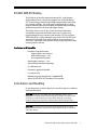
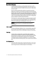
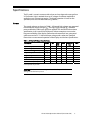
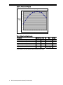
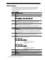
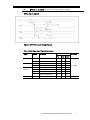
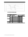
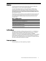
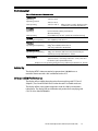
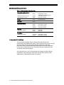
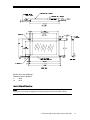
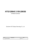
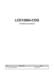
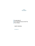
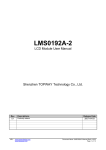
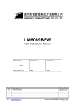
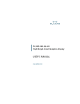
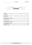
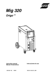
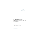
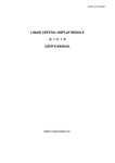
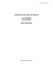
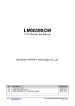
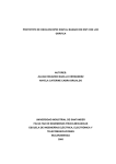
EL240.128.45
ICEBrite™ EL Small Graphics Display
USER’S MANUAL
www.planar.com
Revision Control
Date
Description
August 2000
Document number OM320-00
June 2004
Document number 020-0345-00A
Contents
EL240.128.45 Display................................................................................................................................................3
Features ....................................................................................................................................................................3
Installation and Handling........................................................................................................................................3
Mounting EL Displays ..........................................................................................................................................4
Cable Length...........................................................................................................................................................4
Cleaning ...................................................................................................................................................................4
Avoiding Burn-In ...................................................................................................................................................4
Specifications ..............................................................................................................................................................5
Power.........................................................................................................................................................................5
Connector ................................................................................................................................................................7
Interface Information...........................................................................................................................................8
Video Input Signals.......................................................................................................................................... 9
Dimming ................................................................................................................................................................11
Self-Test Mode......................................................................................................................................................11
Power-up Sequence...........................................................................................................................................11
Optical.....................................................................................................................................................................12
Command Description......................................................................................................................................12
Required register settings and configuration items..........................................................................12
Environmental......................................................................................................................................................13
Reliability................................................................................................................................................................13
Safety and EMI Performance ...........................................................................................................................13
Mechanical Characteristics ..............................................................................................................................14
Component Envelope .......................................................................................................................................14
Description of Warranty ........................................................................................................................................16
Ordering Information .............................................................................................................................................16
Support and Service................................................................................................................................................16
Figures
Figure 1. Power Curve Diagram .......................................................................................................................6
Figure 2. Data/Power Connector - J1 .............................................................................................................7
Figure 3. 8080 Video Input Timing Diagram ...............................................................................................9
Figure 4. 6800 Video Input Timing Diagram .............................................................................................10
Figure 5. Display Dimensions..........................................................................................................................15
Tables
Table 1. DC Input Voltage Requirements. ....................................................................................................5
Table 2. Video Input Requirements. ...............................................................................................................6
Table 3. Connector Pinouts - J1........................................................................................................................7
Table 4. Pin Settings.............................................................................................................................................8
Table 5. 8080 Video Input Timing Description ...........................................................................................9
Table 6. 6800 Video Input Timing Description .........................................................................................10
Table 7. Luminance Control ............................................................................................................................11
Table 8. Optical Characteristics ......................................................................................................................12
Table 9. Environmental Characteristics.......................................................................................................13
Table 10. Mechanical Characteristics ...........................................................................................................14
EL240.128.45 Display
The EL240.128.45 thin film electroluminescent (EL) small graphics
display utilizes Planar’s proprietary Integral Contrast Enhancement
(ICE™) technology to achieve unparalleled image quality without the
use of expensive filters. This small graphics display excels in a wide
range of ambient lighting environments while effectively eliminating
the blooming common to other high-bright displays.
The display consists of an EL glass panel and control electronics
connected using elastomeric interconnects into a space-saving,
rugged package for easy mounting and includes a DC/DC converter.
The EL240.128.45 is easily interfaced using a built-in EPSON SED1335F
standard LCD controller. Each of the pixels has an aspect ratio of 1:1
(V:H) and is individually addressable to clearly display high information
content graphics and text.
Features and Benefits
•
Excellent visual performance:
High brightness and contrast
Wide viewing angle > 160°
No compensation needed
•
Rapid display response < 1 ms
•
Space efficient mechanical package
•
Low EMI emissions
•
Extremely rugged and durable
•
Low power (3 W)
•
Reliable, long operating life with >100,000 MTBF
•
Built-in EPSON SED1335F standard LCD controller
Installation and Handling
Do not drop, bend, or flex the display. Do not allow objects to strike the
surface of the display.
CAUTION: The display uses CMOS and power MOS-FET devices. These
components are electrostatic sensitive. Unpack, assemble, and examine this
assembly in a static-controlled area only. When shipping, use packing
materials designed for protection of electrostatic-sensitive components.
CAUTION: To prevent injury in the event of glass breakage, the use of an
impact resistant shield or a protective overlay should be used on the viewer
side of the display.
EL240.128.45 Operations Manual (020-0345-00A)
3
Mounting EL Displays
Properly mounted, EL displays can withstand high shock loads as well as
severe vibration found in demanding applications. However the glass panel
used in an EL display will break if subjected to bending stresses, high impact,
or excessive loads.
Stresses are often introduced when a display is mounted into a product.
Ideally, the mounting tabs of the display should be the only point of contact
with the system. Use a spacer or boss for support; failure to do so will bend the
display and cause the glass to break. The instrument enclosure or frame should
not flex or distort in such a way that during use the bending loads might be
transferred to the display. Mounting surfaces should be flat to within ±0.6 mm
(±.025"). Use all the mounting holes provided. Failure to do so will impair the
shock and vibration resistance of the final installation.
The EL240.128.45 is a tab mounted display. Use appropriate length standoffs
to assure that screws through the mounting tabs do not introduce bending
stresses into the display. Do not deflect the ECB out of its normal plane. The
EL240.128.45 mounting tabs were designed for a 3 mm screw.
WARNING: These products generate voltages capable of causing personal
injury (high voltage up to 230 Vac ). Do not touch the display electronics
during operation.
Cable Length
A maximum cable length of 600 mm (24 in.) is recommended. Longer cables
may cause data transfer problems between the data transmitted and the
display input connector. Excessive cable lengths can pick up unwanted EMI.
Cleaning
As with any glass or coated surface, care should be taken to minimize
scratching. Clean the display glass with mild, water-based detergents only.
Apply the cleaner sparingly to a soft cloth, then wipe the display. Disposable
cleaning cloths are recommended to minimize the risk of inadvertently
scratching the display with particles embedded in a re-used cloth. Particular
care should be taken when cleaning displays with anti-glare and anti-reflective
films.
Avoiding Burn-In
As with other light emitting displays, displaying fixed patterns on the screen
can cause burn-in, where luminance variations can be noticed. Use a screen
saver or image inversion to avoid causing burn-in on the display.
4
EL240.128.45 Operations Manual (020-0345-00A)
Specifications
The EL panel is a matrix structure with column and row electrodes arranged in an
X-Y formation. Light is emitted when an AC voltage of sufficient amplitude is
applied at a row-column intersection. The display operation is based on the
symmetric, line-at-a-time data addressing scheme.
Power
The supply voltages are shown in Table 1. All internal high voltages are generated
from the display supply voltage (VH). The logic supply voltage (VL) should be
present whenever video input signals are applied. The minimum and maximum
specifications in this manual should be met, without exception, to ensure the
long-term reliability of the display. Performance characteristics are guaranteed
when measured at 25 °C with rated input voltage unless otherwise specified.
Planar does not recommend operation of the display outside these specifications.
Table 1. DC Input Voltage Requirements.
Description
Input voltage (nom=12.0V)
Input voltage absolute max.
Input current (VH =12.0V)
Logic voltage (nom=5.0V)
Logic voltage absolute max.
Logic current
Power consumption @120 Hz
Power consumption @240 Hz
Name
Min
VH
VH max
IH
VL
VL max
IL
8
--4.75
-0.5
--
Typ*
(W)
Max
Absolute
Max
18.0
19.0
0.95
5.25
6.0
3.1
5.8
90
5.5
10.9
Units
Vdc
Vdc
Adc
Vdc
Vdc
mAdc
W
W
*15% of pixels on per row
CAUTION: Absolute maximum ratings are those values beyond which
damage to the device may occur.
EL240.128.45 Operations Manual (020-0345-00A)
5
Figure 1. Power Curve Diagram
Power vs. ON-pixels @ 120 Hz
100
90
80
70
Relative
power
(%)
60
50
40
30
20
10
0
0%
10%
20%
30%
40%
50%
60%
70%
80%
90%
100%
ON-pixels
Table 2. Video Input Requirements.
Description
Symbol
Min
Max
Units
Absolute Input Voltage Range
VI max
-0.3
VL + 0.3
V
Low-level input voltage
VIL
0
0.2 x VL
V
HIgh-level input voltage (except SEL1)
HIgh-level input voltage SEL1, /RES
VIH
0.5 x VL
0.8 x VL
VL
VL
V
IL
–
±10 (-2000)
µA
Logic input current*
* Signals /WR, /CS, SEL1, /RD, SELFTEST, /RES have pullup resistors (4.7k)
6
EL240.128.45 Operations Manual (020-0345-00A)
Connector
Video signals and DC power are supplied to the display through a single 24pin, dual-row, 2 mm pitch square pin, right-angle, locking connector: Samtec
part number EHT-112-01-S-D-RA, or an equivalent connector matching the
pinouts in Table 3. The mating connector is the Samtec TCSD family of cable
strips. Consult your Samtec representative (1-800-SAMTEC9) for cable and
connector options.
(Back of display)
(Viewed from top of connector)
Key
Pin 1
Pin 2
J1
Pin 1
(Bottom of display)
Figure 2. Data/Power Connector – J1.
Table 3. Connector Pinouts J1.
Pin
Signal
Description
Pin
Signal
Description
1
VH
Display voltage
2
VH(+12 V)
3
GND
Ground
4
GND
Ground
5
VL (+5 V)
Logic voltage
6
RES
Reset
7
/WR
Write
8
/RD
Read
9
/CS
Chip Select
10
A0
Address
11
SELFTEST
12
GND
Ground
13
D0
input/output
14
D1
input/output
15
D2
input/output
16
D3
input/output
17
D4
input/output
18
D5
input/output
19
D6
input/output
20
D7
input/output
21
SEL1
Select Interface
22
READY
Display ready
23
GND
Ground
24
LUMA
Luminance control
EL240.128.45 Operations Manual (020-0345-00A)
7
Interface Information
This Small Graphics Display (SGD) incorporates an interface that is compatible
with the 8-bit microprocessor interfaces found in comparable LCD displays with
built-in controllers. The display incorporates a built-in EPSON SED1335F
standard LCD controller.
Table 4. Pin Settings.
Signal
D0 to D7
SEL1
/RD or E
/WR or
R//W
/RES
READY
/CS
A0
SELF-TEST
VL (+5V)
VH (+12V)
LUMA
8
Functional Description
Pins 13-20: Tristate input/output pins. Connect to an 8- or 16-bit microprocessor
bus.
Pin 21: Microprocessor interface select. Both 8080-family processors and 6800-family
processors are supported. SEL1 should be tied directly to VL or GND to prevent noise.
SEL1
Interface
A0
/RD
/WR
/CS
0
8080 family
A0
/RD
/WR
/CS
1
6800 family
A0
E
R//W
/CS
Pin 8: With the 8080 interface, this signal acts as the active-LOW read strobe.
With the 6800 interface, this signal acts as the active-HIGH enable clock. Data is read
from or written to the display when this clock goes HIGH.
Pin 7: With the 8080 interface, this signal acts as the active-LOW write strobe. The
bus data is latched on the rising edge of this signal.
With the 6800 interface, this signal acts as the read/write control signal. Data is read
from the display if this signal is HIGH, and written to the display if it is LOW.
Pin 6: When low resets SED 1335, must be high or unconnected in normal operation
Pin 22: OUTPUT When data for Row 128 is written to display drivers this signal goes
high. While the signal is high it is possible to write data to SED 1335 memory so that
it does not cause disturbances to display data. This signal goes low at latest 3.5 µs
before when loading of Row 1 data begins. Signal READY output is CMOS with 100
ohm series resistor.
Pin 9: Chip select. This active-LOW input enables the SED1335F. It is usually
connected to the output of an address decoder device that maps the
SED1330F/1335F/1336F into the memory space of the controlling microprocessor.
Pin 10: A0, in conjunction with the /RD and /WR or R//W and E signals, control the
type of access to the display, as shown below.
8080 Family Interface
A0
/RD
/WR
Function
0
0
1
Status flag read
1
0
1
Display data and cursor address read
0
1
0
Display data and parameter write
1
1
0
Command write
6800 Family Interface
A0
/RD
/WR
Function
0
1
1
Status flag read
1
1
1
Display data and cursor address read
0
0
0
Display data and parameter write
1
0
1
Command write
Pin 11: This pin should be connected to GND for normal display operation. When
high, display operates in SELFTEST mode
Pin 5: +5V logic supply voltage
Pins 1 and 2: +12V supply for DC-DC converter and display analog circuits
Pin 24: Luminance control input
EL240.128.45 Operations Manual (020-0345-00A)
GND
Pins 3, 4, 12, and 23: Signal return for logic and power supplies
Video Input Signals
Figure 3. 8080 Video Input Timing Diagram.
Table 5. 8080 Video Input Timing Description.
Signal
A0, CS
WR, RD
D0 to D7
All signals
Symbol
Parameter
Condition
min
max
unit
tAH8
Address hold time
10
-
ns
tAW8
tCYC
tCC
tDS8
tDH8
tACC8
tOH8
Tr, Tf
Address setup time
System cycle time
Strobe pulsewidth
Data setup time
Data hold time
RD access time
Output disable time
Input rise and fall times
0
550
120
120
5
10
50
50
30
ns
ns
ns
ns
ns
ns
ns
ns
CL=100pF
EL240.128.45 Operations Manual (020-0345-00A)
9
Figure 4. 6800 Video Input Timing Diagram.
Table 6. 6800 Video Input Timing Description.
Signal
Symbol
Parameter
A0, /CS,
tCYC6
System cycle time
R//W
tAW6
tAH6
tDS6
tDH6
tOH6
tACC6
tEW
Tr, Tf
Address setup time
Address hold time
Data setup time
Data hold time
Output disable time
Access time
Enable pulsewidth
Input rise and fall times
D0 to D7
E
All signals
10 EL240.128.45 Operations Manual (020-0345-00A)
Condition
min
550
max
-
Unit
ns
0
0
100
0
10
120
50
85
ns
ns
ns
ns
ns
30
ns
CL=100pF
Dimming
The dimming control circuitry on the display allows the user to adjust the
luminance from 5% to 95% of the maximum brightness.
To control the display luminance, connect a 50 k (ohm) variable resistor
between ground and the dimming pin (LUMA). The full resistance of 50 k
(ohm) will result in 95% of the maximum luminance. Reducing the resistance
will reduce the luminance, with resistance of 0 k (ohm) yielding roughly 5% of
the maximum luminance.
Alternatively an external voltage or current-mode D/A converter may be used
to dim the display by sinking a maximum of 250 µA for maximum dimming
from LUMA to ground. When left open, the luminance will remain at the
maximum level.
Table 7. Luminance Control.
Maximum (No resistor connected): 100% (Default)
Maximum (50 k Ω resistor connected): 95 %
Minimum (0 Ω resistor connected):
5% maximum
Open Circuit voltage 4 V nominal
Sink Current 250 µA max, Vin = 0V
Luminance values are measured as a percentage of full On Luminance (with
the external resistor disconnected.)
Self-Test Mode
The display incorporates a self-test mode composed of a 1 x 1 checkerboard
and full-on pattern displayed at 240 Hz. Upon power up, the 1 x 1 pattern is
displayed for several seconds, then the full-on pattern is displayed
continuously. The self-test mode is entered by leaving the SELFTEST pin pulled
high. For normal operation the SELFTEST pin must be pulled to a logic low. If
the SELFTEST pin is pulled high during normal operation, the display will enter
the self-test mode with the all-pixels-on pattern.
Power-up Sequence
No special power-up or video sequencing is required.
EL240.128.45 Operations Manual (020-0345-00A)
11
Optical
Table 8. Optical Characteristics.
Luminance
Lon (areal), typ
Lon (areal), min
Loff (areal), max
65 cd/m²
130 cd/m²
45 cd/m²
90 cd/m²
0.30 cd/m²
@ 120 Hz
@ 240 Hz
@ 120 Hz
@ 240 Hz
@ 240 Hz
Non-uniformity
All pixels fully lit
25%
Maximum difference between any
2 of 5 points, using the formula:
LNU%=[1- (min_lum/max_lum)] x 100%
Luminance Variation (Temperature)
Maximum
±20%
From 25 °C to operating temp. extremes; all
pixels on.
Luminance Variation (Time)
Maximum
<20%
10,000 hours at 25°C ambient; all pixels on.
Viewing Angle
Minimum
>160°
Contrast Ratio
500 lux
5000 lux
55:1 @ 120 Hz frame rate; 97:1 @ 240 Hz frame rate
7.1:1 @ 120 Hz frame rate; 13:1 @ 240 Hz frame rate
Command Description
The EL240.128.45 display is driven by the EPSON SED1335F controller. For details on
using this controller, refer to the Command Description section of the SED 1335
technical manual titled SED1330F/1335F/1336F LCD Controller ICs Technical
Manual. This document is on the EPSON website at www.epson-electronics.de
Required register settings and configuration items
• The module uses one 32kx8 SRAM for all CG and display memory.
• W/S, bit 3 of the P1 byte of the SYSTEM SET instruction, is set to 0 for a
single drive panel.
• DR, bit 7 of the P1 byte of the SYSTEM SET instruction, is set to 0 to turn off
the additional output cycle of the shift clock
• The recommended SYSTEM.SET parameter values are (P1 through P8) in
hex, for a frame rate of 240 Hz: 32, 07, 07, 1D, 23, 7F, 1E, and 00.
• P5 must not be less than 23 to guarantee that minimum line period
requirement of the display is achieved (32.5us)
• The READY flag is high during extra line times, so P6 should be over 7F if the
READY flag is used. After the falling edge of the READY flag there is min. 3.5
µs time to end the display memory write cycle.
• Oscillator frequency to EPSON SED1335F is 10 MHz
12 EL240.128.45 Operations Manual (020-0345-00A)
Environmental
Table 9. Environmental Characteristics.
Temperature
Operating
Operating survival
Non-operating
Humidity
Operating
-20 °C to +70 °C
-40 °C to +85 °C
-50 °C to +105 °C
After 12 hours at -50°C, display must be
at -40°C for 1 hour prior to power on.
Non-operating
to 93% RH max @ 40ºC, per IEC 68-2-3
(Non-condensing)
to 95% RH max @ 25-55°C, per IEC 68-2-30 (Condensing)
Altitude
Operating/non-operating
0 to 18,000 m per IEC 68-2-13
Vibration
Operating/non-operating
Mechanical Shock
Operating/non-operating
2
0.02g /Hz, 5-500 Hz, 30 minutes on
each axis, per IEC 68-2-36, Random
100 g, 6 ms duration (half sine wave), three shocks per
surface (6), tested per IEC 68-2-27, Test Ea
Thermal Shock
-40°C for 30 min., room temperature for ~3 min., then 85°C
for 30 min. Cycle repeated five times.
Displays are non-operating during the tests performed per IEC 68-2-14. Test Na.
Reliability
The display MTBF is demonstrated to be greater than 100,000 hours at
maximum frame rate with a 90% confidence level at 25°C.
Safety and EMI Performance
The display will not inhibit the end product from complying with FCC Part 15
Subpart J, Class B and EN55022 Class B when housed in a suitable enclosure.
The display will be a recognized component under UL1950 by Underwriters
Laboratories. The display will not inhibit the end product from complying with
CSA C22.2 No. 950 and EN60950.
EL240.128.45 Operations Manual (020-0345-00A)
13
Mechanical Characteristics
Table 10. Environmental Characteristics.
Display External Dimensions
millimeters (inches)
width
without locking connector
with locking connector
height
depth
128.0 (5.04) nominal
~140.0 mm w/ mounting ears
77.0 (3.03) nominal
14.8 (0.59) nominal
Weight
115g
(4.1 oz) nominal
Fill Factor
71.3%
Display Active Area
millimeters (inches)
Pixel Size
millimeters (inches)
Pixel Pitch
millimeters (inches)
width
height
diagonal
107.9 (4.25) nominal
57.5 (2.26) nominal
122.3 (4.8) nominal
width
height
0.26 (0.01)
0.26 (0.01)
horizontal
vertical
0.45 (0.018) nominal
0.45 (0.018) nominal
Component Envelope
The component envelope shown in Figure 4 illustrates the distance
components extend behind the display. Tall components do not necessarily fill
this area. Planar reserves the right to relocate components within the
constraints of the component envelope without prior customer notification.
For this reason, Planar advises users to design enclosure components to be
outside the component envelope.
An air gap of at least 5 mm is recommended to dissipate heat from display
components. Device designers will need to consider their specific system
requirements to determine the necessary spacing.
14 EL240.128.45 Operations Manual (020-0345-00A)
Dimensions in are millimeters.
Tolerances unless specified:
.x
±0.50
±0.25
.xx
Figure 5. Display Dimensions.
Note: This is not a controlled version of the mechanical drawing. Prior to beginning your
design, please contact Planar Applications Engineering for the current detailed drawing.
EL240.128.45 Operations Manual (020-0345-00A)
15
Description of Warranty
Seller warrants that the Goods will conform to published specifications and be free from defects in
material for 12 months from delivery. To the extent that Goods incorporate third-party-owned
software, Seller shall pass on Seller's licensor's warranty to Buyer subject to the terms and conditions
of Seller's license.
Warranty repairs shall be warranted for the remainder of the original warranty period. Buyer shall
report defect claims in writing to Seller immediately upon discovery, and in any event, within the
warranty period. Buyer must return Goods to Seller within 30 days of Seller’s receipt of a warranty
claim notice and only after receiving Seller’s Return Goods Authorization. Seller shall, at its sole
option, repair or replace the Goods.
If Goods were repaired, altered or modified by persons other than Seller, this warranty is void.
Conditions resulting from normal wear and tear and Buyer's failure to properly store, install, operate,
handle or maintain the Goods are not within this warranty. Repair or replacement of Goods is
Seller’s sole obligation and Buyer's exclusive remedy for all claims of defects. If that remedy is
adjudicated insufficient, Seller shall refund Buyer's paid price for the Goods and have no other
liability to Buyer.
All warranty repairs must be performed at Seller’s authorized service center using parts approved by
Seller. Buyer shall pay costs of sending Goods to Seller on a warranty claim and Seller shall pay costs
of returning Goods to Buyer. The turnaround time on repairs will usually be 30 working days or less.
Seller accepts no added liability for additional days for repair or replacement.
If Seller offers technical support relating to the Goods, such support shall neither modify the
warranty nor create an obligation of Seller. Buyer is not relying on Seller’s skill or judgment to select
Goods for Buyer’s purposes. Seller’s software, if included with Goods, is sold as is, and this warranty
is inapplicable to such software.
SELLER DISCLAIMS ALL OTHER WARRANTIES, EXPRESS OR IMPLIED, INCLUDING BUT NOT LIMITED
TO, IMPLIED WARRANTIES OF MERCHANTABILITY AND FITNESS FOR A PARTICULAR PURPOSE.
Ordering Information
Product
Part Number
Features
EL240.128.45
996-0301-01
Standard version
Design and specifications are subject to change without notice.
Planar Systems continues to provide optional, and in many cases custom, features to address the
specific customer requirements. Consult Planar Sales for pricing, lead time and minimum quantity
requirements.
Support and Service
Planar is a U.S. company based in Beaverton, Oregon and Espoo, Finland, with a world-wide sales
distribution network. Full application engineering support and service are available to make the
integration of Planar displays as simple and quick as possible for our customers.
RMA Procedure: For a Returned Material Authorization number, please contact Planar Systems, Inc.
with the model number(s) and serial number(s). When returning goods for repair, please include a
brief description of the problem, and mark the outside of the shipping container with the RMA
number.
16 EL240.128.45 Operations Manual (020-0345-00A)
Planar Systems, Inc.
Customer Service
24x7 Online Technical Support: http://www.planar.com/support
Americas Support
1195 NW Compton Drive
Beaverton, OR 97006-1992
Tel: 1-866-PLANAR1 (866) 752-6271
Hours: M-F, 5am - 5pm Pacific Time
Europe and Asia-Pacific Support
Olarinluoma 9 P.O. Box 46
FIN-02201 Espoo, Finland
Tel: +358-9-420-01
Hours: M-F, 7:00am - 4pm CET
© 2004 Planar Systems, Inc. 06/04 Planar is a registered trademark of Planar Systems, Inc.
ICE, ICEBrite, and ICEPlus are trademarks of Planar Systems, Inc.
Other brands and names are the property of their respective owners.
Technical information in this document is subject to change without notice.
020-0345-00A