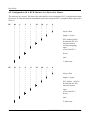
1
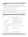
CAN - CSC595/2
CAN - PLC Interface Module
for
S5-90U, S5-95U and S5-100U
DeviceNet
Software Manual
CAN CSC595/2 DeviceNet Manual Rev. 1.2
DeviceNet
NOTE
The information in this document has been carefully checked and is believed to be entirely reliable. esd
makes no warranty of any kind with regard to the material in this document, and assumes no
responsibility for any errors that may appear in this document. esd reserves the right to make changes
without notice to this, or any of its products, to improve reliability, performance or design.
esd assumes no responsibility for the use of any circuitry other than circuitry which is part of a product
of esd gmbh.
esd does not convey to the purchaser of the product described herein any license under the patent rights
of esd gmbh nor the rights of others.
esd electronic system design gmbh
Vahrenwalder Str. 205
D-30165 Hannover
Germany
Tel:
Fax:
Email:
+49-511-372-980
+49-511-633-650
[email protected]
CAN CSC595/2 DeviceNet Manual Rev. 1.2
DeviceNet
Manual File:
I:\TEXTE\DOKU\MANUALS\CAN\CSC595.2\SC0512SD.EN6
Date of Print:
28/10/97
Described Software:
DeviceNet driver for CSC595/2
CSC595/2 Kernel
V0.1f
V0.2b
Revision/Date:
Changes in the chapters
The changes in the user’s manual listed below affect changes in the software, as well as changes in the
description of the facts only.
Firmware Manual
Version
CSC595/2
V1.2
Chapter
Alterations as compared to version 1.0
1.3
Commands DM, SM, and SY deleted in document, because
they are designed for service and programming only.
4.2
PLC address in example changed.
-
-
Technical details are subject to change without notice.
CAN CSC595/2 DeviceNet Manual Rev. 1.2
DeviceNet
CAN CSC595/2 DeviceNet Manual Rev. 1.2
DeviceNet
1. Configuration Commands via RS-232 . . . . . . . . . . . . . . . . . . . . . . . . . . . . . . . . . . . . . . . . . . . . 3
1.1 Introduction . . . . . . . . . . . . . . . . . . . . . . . . . . . . . . . . . . . . . . . . . . . . . . . . . . . . . . . . . . . 3
1.2 Common Commands . . . . . . . . . . . . . . . . . . . . . . . . . . . . . . . . . . . . . . . . . . . . . . . . . . . . 3
1.2.1 Save Configuration . . . . . . . . . . . . . . . . . . . . . . . . . . . . . . . . . . . . . . . . . . . . . . 3
1.2.2 Set Bit Rate, Display Bit Rate . . . . . . . . . . . . . . . . . . . . . . . . . . . . . . . . . . . . . . 4
1.2.3 Wakeup Time . . . . . . . . . . . . . . . . . . . . . . . . . . . . . . . . . . . . . . . . . . . . . . . . . . 5
1.2.4 Module Number . . . . . . . . . . . . . . . . . . . . . . . . . . . . . . . . . . . . . . . . . . . . . . . . 6
1.2.5 Reset Module . . . . . . . . . . . . . . . . . . . . . . . . . . . . . . . . . . . . . . . . . . . . . . . . . . 6
1.2.6 CAN Default . . . . . . . . . . . . . . . . . . . . . . . . . . . . . . . . . . . . . . . . . . . . . . . . . . . 6
1.3 Additional Common Commands . . . . . . . . . . . . . . . . . . . . . . . . . . . . . . . . . . . . . . . . . . . 7
1.3.1 Help . . . . . . . . . . . . . . . . . . . . . . . . . . . . . . . . . . . . . . . . . . . . . . . . . . . . . . . . . . 7
1.4 Configuring the DeviceNet interface . . . . . . . . . . . . . . . . . . . . . . . . . . . . . . . . . . . . . . . . 8
1.4.1 Scanner Parameter . . . . . . . . . . . . . . . . . . . . . . . . . . . . . . . . . . . . . . . . . . . . . . . 8
1.4.2 Installing COMM_ID (with PAM-scanner only) . . . . . . . . . . . . . . . . . . . . . . . 8
1.4.3 Slave Parameter . . . . . . . . . . . . . . . . . . . . . . . . . . . . . . . . . . . . . . . . . . . . . . . . 9
1.5 Configuration of the PLC Interface . . . . . . . . . . . . . . . . . . . . . . . . . . . . . . . . . . . . . . . . 10
1.5.1 Slotnumber . . . . . . . . . . . . . . . . . . . . . . . . . . . . . . . . . . . . . . . . . . . . . . . . . . . 10
1.5.2 Data Window . . . . . . . . . . . . . . . . . . . . . . . . . . . . . . . . . . . . . . . . . . . . . . . . . 11
1.5.3 PLC - DeviceNet Mapping Table . . . . . . . . . . . . . . . . . . . . . . . . . . . . . . . . . . 12
2. The Command Page . . . . . . . . . . . . . . . . . . . . . . . . . . . . . . . . . . . . . . . . . . . . . . . . . . . . . . . . . . 13
2.1 Module State . . . . . . . . . . . . . . . . . . . . . . . . . . . . . . . . . . . . . . . . . . . . . . . . . . . . . . . . . 13
2.2 Command Interface . . . . . . . . . . . . . . . . . . . . . . . . . . . . . . . . . . . . . . . . . . . . . . . . . . . . 14
3. Meaning of the CAN/DvN-LED in Front of the Module . . . . . . . . . . . . . . . . . . . . . . . . . . . . 16
4. Examples . . . . . . . . . . . . . . . . . . . . . . . . . . . . . . . . . . . . . . . . . . . . . . . . . . . . . . . . . . . . . . . . . . . 17
4.1 Configuration Of A FESTO Pneumatic Valves Unit As A DeviceNet Slave . . . . . . . . 17
4.2 Configuration Of A KUKA Robot As A DeviceNet Master . . . . . . . . . . . . . . . . . . . . . 22
CAN CSC595/2 DeviceNet Manual Rev. 1.2
1
DeviceNet
2
CAN CSC595/2 DeviceNet Manual Rev. 1.2
DeviceNet
1. Configuration Commands via RS-232
1.1 Introduction
The RS-232 interface is used for configurating and debugging. It can be used by a terminal or a PC
with a terminal program (i.e. Windows terminal) with the following parameters:
Bit rate:
19200 baud
Data:
8 bit
Parity: no parity
Stop bit:
1 stop bit
Handshake: no handshake
All written parameters are interpreted as HEX-values !!!! (In this document HEX values are marked
with an ‘$’in front of the given value.)
The configuration parameters are only valid after storing them into the internal EEPROM (‘CS’)
and resetting the module (e.g. by command ‘RS’or by power_up).
An individual help to each command is printed by pressing the command with a following ‘?’.
1.2 Common Commands
1.2.1 Save Configuration
Name:
Save configuration
Input command syntax:
CS
Input parameter syntax:
> ok
> error
Description:
All actual configuration parameters are stored into the internal EEPROM. The module answers with
an ‘ok’, if well done, or with ‘error’, if an error occurred. The parameters are only valid until the next
reset of the module.
CAN CSC595/2 DeviceNet Manual Rev. 1.2
3
DeviceNet
1.2.2 Set Bit Rate, Display Bit Rate
Name:
Set bit rate
Input command syntax:
SB
Input parameter syntax:
< index(0-$F)/register-format
Name:
Display bit rate
Input command syntax:
DB
Output parameter syntax:
> index(0-$F)/register-format
The default bit rate is set by the coding switch at the front panel:
Setting of coding switch
Default-bit rate
[Kbit/s]
0
1
2
125
250
500
Table 1.2.1: Setting of default bit rate
This bit rate can be overwritten by the command ‘SB’, with any value except $FFFF. The new value
can be displayed by calling the command ‘DB’.
4
CAN CSC595/2 DeviceNet Manual Rev. 1.2
DeviceNet
The bit rate can be given as index (0...$F) or as the direct register format (intel CAN controller,
20 MHz):
Index
[HEX]
Register
[HEX]
0
1
2
3
4
5
6
7
8
9
A
B
C
D
E
F
0x1600
0x1b00
0x2f00
0x1b01
0x2f01
0x2f02
0x1c04
0x2f04
0x1b09
0x2f09
0x2f0e
0x2f18
0x2f27
0x2f31
0x7f7f
0x1200
Bit rate
[bit/s]
1M
666 K
500 K
333 K
250 K
166 K
125 K
100 K
66 K
50 K
33 K
20 K
12.5 K
10 K
6K
1.6 M
Table 1.2.2: Setting bit rate by command
1.2.3 Wakeup Time
Name:
Wakeup time
Input command syntax:
WU
I/O parameter syntax:
<> time(ms)
Description:
After wakeup the module waits for the duration of the given wakeup time before is starts with any
action at the CAN.
Acceptable values are 0...$7FFF, according to 0...32767 ms. If the command is called without a
parameter value, the actual value of the parameter is displayed at the monitor.
CAN CSC595/2 DeviceNet Manual Rev. 1.2
5
DeviceNet
1.2.4 Module Number
Name:
Module number
Input command syntax:
MN
I/O parameter syntax:
<> number(1-$3F)
Description:
The MAC_ID of the module is set by this command. If the command is called without a parameter
value, the actual value of the MAC_ID is displayed at the monitor.
1.2.5 Reset Module
Name:
Reset module
Input command syntax:
RS
I/O parameter syntax:
No parameters
Description:
This commands is an easy way to reset the module (instead of a power_up).
1.2.6 CAN Default
Name:
CAN default
Input command syntax:
CD
I/O parameter syntax:
No parameters
Description:
With this command, all parameter are defaulted (but not actually stored in the EEPROM).
6
CAN CSC595/2 DeviceNet Manual Rev. 1.2
DeviceNet
1.3 Additional Common Commands
1.3.1 Help
Name:
Help
Input command syntax:
??
Output parameter syntax:
> commands
Description:
This command returns a list of all possible commands (without following supervisor commands).
CAN CSC595/2 DeviceNet Manual Rev. 1.2
7
DeviceNet
1.4 Configuring the DeviceNet interface
1.4.1 Scanner Parameter
Name:
Scanner parameter
Input command syntax:
SC
I/O parameter syntax:
<> scan_nr MAC_ID rxlen txlen rate
Parameter description:
scan_nr:
table index (0...$1F)
MAC_ID:
MAC_ID of the module. that should be scanned
rxlen:
Length of the produced data of that module (0...$FE)
txlen:
Length of the consumed data of that module (0...$FE)
rate:
Expected package rate of the connection (0 - $FFFF)
Command description:
This command installs a module to the internal scanner. The ‘scan_nr’means the table number of this
entry. The scanner polls all modules written in this table up to the first not written entry. If an entry
should be deleted, just type ‘SC nr -’ and the scanner stops at this point. The ‘rxlen’ and ‘txlen’
parameters are checked against the remote module and if a difference is recognized, a configuration
error is shown to the PLC. The expected package rate is written to the remote module and the module
is scanned by the half rate to reduce CAN access.
If the command is called without parameters, the actual values of the parameters are displayed at the
monitor.
1.4.2 Installing COMM_ID (with PAM-scanner only)
Name:
COMM_ ID install
Input command syntax:
CI
Input parameter syntax:
< scan_nr R/T COMM_ID
< scan_nr
>RX_COMM_ID TX_COMM_ID
Output parameter syntax:
Parameter description:
can_nr:
The entry-number from the scanner table above
R/T:
‘R’for a receiving COMM_ID,
‘T’for a transmitting COMM_ID
COMM_ID: COMM_ID (0...$FFFE)
8
CAN CSC595/2 DeviceNet Manual Rev. 1.2
DeviceNet
Command description:
This command installs a COMM_ID for a given scanner entry (refer to 1.5.1). If at least one
COMM_ID is given for a scanner entry, the data length of this entry means the pure net data length
without any COMM_ID. The scanner switches automatically to a special COMM_ID handler, who
builds the correct transmit-frames with COMM_ID rsp. extract raw data from received frames.
COMM_ID can only be added to a given scanner entry, but overwriting a scanner entry clears installed
COMM_ID’s of the old entry.
1.4.3 Slave Parameter
Name:
Slave parameter
Input command syntax:
SL
I/O parameter syntax:
<> rxlen txlen
Parameter description:
rxlen: Consumed_Data_Length (0...$FE)
txlen: Produced_Data_Length (0...$FE)
Command description:
The module can also be accessed by another scanner. You just have to define the
Consumed_Data_Length (rxlen) and the Produced_Data_Length (txlen) with this command.
If the command is called without a parameter value, the actual value of the parameters are displayed
at the monitor.
CAN CSC595/2 DeviceNet Manual Rev. 1.2
9
DeviceNet
1.5 Configuration of the PLC Interface
The interface between the module and the PLC is located in the peripheral address range of the PLC.
The absolute address of the module depends on the slotnumber of the module. Every slot occupies only
8 byte data of the PLC. To raise the performance of this interface, the module is able to simulate more
than one slot. Due to this simulation the addresses of the following modules on the PLC bus are shifted
to slots behind the last simulated slot.
There are generally two ways to access the data of DeviceNet:
1.
Direct access through I/O-addresses is an easy and quick way to write and read data. It is just
necessary to make a mapping table between I/O-addresses and DeviceNet data. The
disadvantage is the small I/O data area of the PLC and the larger PLC cycle time simulating
more data.
2.
Indirect access through a command and a data window.
The command window is fixed in the first 4 bytes of the first simulated slot, input and output.
So the module must be inserted in an ‘analog slot’, i.e. one of the first 8 slots!!! The data
window is definable in address and range.
1.5.1 Slotnumber
Name:
Slot number
Input command syntax:
SN
I/O parameter syntax:
<> slot
Parameter description:
slot: slotnumber (0...7)
Command description:
Calling this command stores the slotnumber of the module. The module needs this number, to
recalculate the relative address positions from absolute addresses. The absolute addresses are set by the
commands described in the following chapters.
The slot number is necessary to communicate with the PLC.
10
CAN CSC595/2 DeviceNet Manual Rev. 1.2
DeviceNet
1.5.2 Data Window
Name:
Window
Input command syntax:
WD
I/O parameter syntax:
< I/O addr len
> I addr len
O addr len
Parameter description:
I:
Input Window, PLC can read data from DeviceNet
O:
Output Window, PLC can write data to DeviceNet
addr: Absolute address of the window
len:
Length of the window (0,2,4,8)
Command description:
This command defines the address and the range of the data window. Using this data window and
additional the command window the PLC can access to the whole data area of the DeviceNet interface
(chapter 2).
If the command is called without parameter values, the actual values of the parameters are displayed
at the monitor.
CAN CSC595/2 DeviceNet Manual Rev. 1.2
11
DeviceNet
1.5.3 PLC - DeviceNet Mapping Table
Name:
PLC parameter
Input command syntax:
PP
I/O parameter syntax:
<
<
<
<
>
nr
nr
nr
nr
nr
M P I/O M/I addr len MAC_ID offs
M P I/O M/I addr len MAC_ID offs COMM_ID
S P I/O M/I addr len offs
E
M/S/E P I/O M/I addr len [MAC_ID] offs [COMM_ID]
|
| |
|
|
| |
MOTOROLA / INTEL notation
|
| Input / Output
|
Peripheral area
access to Master / Slave, or table-End
Parameter description:
nr:
Table index (0...$3F)
addr:
Absolute PLC address of this entry
len:
Data length of this entry
MAC_ID:
DeviceNet MAC_ID of the module, that should be accessed (Master only)
offs:
Offset inside the data stream of the device
COMM_ID: COMM_ID of the data object (only on devices with special COMM_ID handling)
Command description:
This command installs a data mapping table between PLC and DeviceNet to perform direct data
exchange. The link is made between PLC peripheral input or output (‘I/O’) address ‘addr’ with data
length ‘len’and DeviceNet data from the remote module ‘MAC_ID’(via Master ‘M’) or from the own
module (via Slave interface ‘S’) after position ‘offs’ of the data stream depending on the direction
(I/O).
If it is a remote device with the special COMM_ID handling, the COMM_ID in this entry is necessary
to distinguish between several objects.
SPECIAL:
A special feature is made with the ‘M/I’letter: The PLC accesses to words in MOTOROLA notation,
means a high-byte/low-byte orientation inside the PLC. Because most DeviceNet data is orientated in
INTEL notation (low-byte/high-byte), it is possible to change this orientation with the ‘I’letter. This
is only possible with a even data length, otherwise it is switched back automatically.
The table ends at a special entry written with ‘PP nr E’. If no parameter is written, this command shows
the complete table.
12
CAN CSC595/2 DeviceNet Manual Rev. 1.2
DeviceNet
2. The Command Page
The easiest and quickest data access is done with the mapping table (refer to 1.5.1). But it maybe
possible that not all data is directly accessible due to the small peripheral address range of the PLC.
Therefore it is possible to perform an indirect access with a command and a data window.
The data window is definable with the ‘WD’ command (refer to 1.5.2). The command window
occupies the first 4 bytes of the module, input and output.
In input direction it holds some state information of the module. In output direction the PLC program
can send a command with several specifier to the module. The module recognize a new command only,
if at least one bit of this window is changed. So, if nobody writes to the command window, no
command is executed and the old command has not to be reset.
2.1 Module State
The command window shows in input direction the state of the module. The memory layout with ‘n’
as the base address of the module is:
IB n:
IB n+1:
IB n+2 \
IB n+3 - IW n+2:
state bits
error MAC_ID
special information, command dependent
The state bits in the first input byte are:
I n.7 : can_off
I n.6 : can_warn
I n.5 : scan_ok
I n.4 : slave_ok
I n.3 : config_error
I n.2 : future use
I n.1 : success
I n.0 : toggle
The bits ‘can_off’and ‘can_warn’show the actual state of the CAN chip.
‘scan_ok’shows, if the internal scanner is connected to all slaves of the scan-table.
The bit ‘slave_ok’means, that the internal slave interface is connected by another scanner. If the data
length of the slave is zero, this bit is always set.
The bit ‘config_error’shows a configuration error like ‘Duplicate_MACID’or ‘wrong data size’
in scan-table.
CAN CSC595/2 DeviceNet Manual Rev. 1.2
13
DeviceNet
The bits ‘success’and ‘toggle’belongs directly to the command interface:
‘toggle’ toggles after each finished command. ‘success’ shows, if this command was finished
successfully.
The second input byte shows the MAC_ID of the module, which caused the last error like ‘timeout’or
‘configuration error’.
The default value is $0xFF.
The second word of the command window is reserved for command dependent return values (future
use).
2.2 Command Interface
Via the command window the PLC can send special commands to the module. A new command is only
recognized by the module, if at least one bit of the command window is changed. So, if nobody writes
to the command window, no command is executed, and the last written command has not to be reset.
A recognized command is finished by set or reset the ‘success’bit and by an inverse ‘toggle’bit. The
memory layout with ‘n’as the base address of the module is:
QB n:
QB n+1:
QB n+2 :
QB n+3:
14
command
subcmmd
\
-QW n+2 : command dependent information
CAN CSC595/2 DeviceNet Manual Rev. 1.2
DeviceNet
Following commands are implemented:
command subcmmd
QB n+2
QB n+3
QW n+2
description
0x00
x
x
No command is executed.
0x01
x
x
Resets error:
The error MACID (IB n+1) is reset to his default value $0xFF.
0x02
MACID
len
off
+0x08=
0x0A
0x03
Reads ‘len’data bytes from device ‘MACID’after data offset
‘off’. If ‘MACID’> $0x3F, data is read from the internal slave
interface.
Converts INTEL to MOTOROLA notation (refer to 1.5.3).
MACID
len
off
Writes ‘len’data bytes to device ‘MACID’after data offset
‘off’ and updates mirror_image to process image.
If ‘MACID’> $0x3F, data is written to the internal slave
interface.
+0x08=
0x0B
Converts INTEL to MOTOROLA notation (refer to 1.5.3).
+0x10=
0x13
Writes only to mirror_image to have consistent data with the
following writes.
+0x08
+0x10=
0x1B
Converts INTEL to MOTOROLA notation and writes only to
mirror_image.
0x04
MACID
+off
COMM_ID
+0x08=
0x0C
0x05
Reads data from object ‘COMM_ID’from PAM device
‘MACID’. The data size is always equal to the whole data
window size, the 2 MSB’s in ‘MACID+off’determine the
offset in steps of the data-window size. Example:
Is the read-data window size 8 bytes and the 2 MSB’s are ‘01’
(=1), the command reads from offset 8.
Converts INTEL to MOTOROLA notation (refer to 1.5.3).
MACID
+off
COMM_ID
Writes data to object ‘COMM_ID’from PAM device
‘MACID’and updates mirror_image to process_image. The
data size is always equal to the whole data window size, the 2
MSB’s in ‘MACID+off’determine the offset in steps of the
data-window size.
+0x08=
0x0D
Converts INTEL to MOTOROLA notation (refer to 1.5.3).
+0x10
0x15
Writes only to mirror_image to have consistent data with the
following writes.
+0x08
+0x10=
0x1D
Converts INTEL to MOTOROLA notation and writes only to
mirror_image.
CAN CSC595/2 DeviceNet Manual Rev. 1.2
15
DeviceNet
3. Meaning of the CAN/DvN-LED in Front of the Module
At start-up the LED indicates the wakeup procedure by changing the colour periodically. During the
wakeup time the module is passive on the CAN. The wakeup time can be set by the command ‘WU’.
LED State
LED off
LED green flashing
LED lights
continuously green
Meaning
The LED is turned off while sending the duplicate MAC-ID request.
After wakeup and duplicate MAC-ID request the LED turns to flashing
green. The communication between DeviceNet participants has not yet
been established.
There is no error and communication has been established
LED red flashing
A time-out has been detected in the communication between one
DeviceNet participant and the CSC595/2.
LED lights
continuously red
A fatal error has occurred. Please check the settings and wiring of attached
DeviceNet nodes.
Table 3.1.1: LED states
16
CAN CSC595/2 DeviceNet Manual Rev. 1.2
DeviceNet
4. Examples
4.1 Configuration Of A FESTO Pneumatic Valves Unit As A DeviceNet Slave
- Set the CAN bit rate of the CSC595 to the same value as all other CAN participants at this CAN
net.
- Additionally it is necessary to define a MAC-ID for each device.
Use the according manuals for the above required settings .
For the following example the MAC_ID of the FESTO pneumatic valves has to be set to 5. All
numbers in the following example has to be set as HEX values.
All commands used in this example are described in the DeviceNet software manuals of these devices
1. Use the command ‘SC’, to setup the slaves that shall be scanned by the master with the following
parameters:
SC
0
*
*
*
*
*
*
*
*
*
.)
5
3
*
*
*
*
*
2
*
*
*
*
*
*
*
*
.)
*
.)
*
64
.)
expected package rate is 100 ms (=$0x64)
-> polling cycle 50 ms
the master shall send 2 bytes to the module *)
the module shall answer with 3 bytes *)
.)
the MAC-ID of the device has to be set to 5
indicates the first entry of the scan table
*) The number of bytes that has to be transferred is device-specific.
The end of the table has to be defined by the same command but without any parameters:
SC
1
*
*
.)
.)
end of table
2nd entry in the scan table
2. Set bit rate to 500 kbit/s
SB
2
.)
bit rate index (2 = 500 kbit/s)
3. Use the command ‘PP’to create the following PLC mapping table (two entries):
CAN CSC595/2 DeviceNet Manual Rev. 1.2
17
DeviceNet
PP
0
*
*
*
*
*
*
*
*
*
*
*
M
*
P
*
*
*
*
*
*
*
*
*
*
*
*
.)
MAC-ID of slave
.)
length = 2 (data)
.)
PLC address $0x4C =
decimal 76 (AW 76)
intel format
output
(view from PLC)
*
*
*
0 byte offset
.)
.)
*
.)
*
*
*
*
*
*
*
*
*
0
*
*
*
*
*
*
*
*
*
5
*
*
*
*
*
*
*
*
*
2
*
*
*
*
*
4C
*
*
*
*
*
I
*
*
*
*
O
*
*
.)
*
P-area
*
*
.)
master (scanner)
*
.)
PP
first table entry
1
*
*
*
*
*
*
*
*
*
*
*
*
*
*
*
*
*
*
*
*
*
*
.)
*
*
*
.)
*
*
*
*
5
*
.)
*
*
.)
.)
0
0 byte offset
MAC-ID of slave
length = 2 (data)
PLC address $0x4C =
decimal 76 (EW 76)
intel format
input
(view from PLC)
*
.)
.)
.)
.)
*
*
*
*
*
*
*
*
*
*
*
*
*
*
*
*
*
*
2
*
*
*
*
*
4C
*
*
*
*
*
*
I
*
*
*
*
*
*
I
*
*
*
*
P
*
*
*
18
M
P-area
master (scanner)
2. table entry
CAN CSC595/2 DeviceNet Manual Rev. 1.2
DeviceNet
4. If you wish to determine the state of the pneumatic valves, you have to set the PLC data mapping
table to the following values:
PP
2
*
*
*
*
*
*
*
*
*
*
*
*
*
*
*
*
*
.)
PP
M
*
*
.)
*
*
*
*
*
*
*
*
*
*
*
*
*
*
*
*
*
*
*
*
*
*
*
5
*
*
*
2
.)
.)
.)
.)
.)
*
*
*
*
*
*
*
*
*
*
*
1
*
*
*
*
*
4E
*
*
*
*
*
M
*
*
*
.)
*
0 byte offset
MAC-ID of slave
length = 1 (status)
PLC address $0x4C =
decimal 78 (EB 78)
motorola format
input
(view from PLC)
*
*
.)
*
P-area
.)
master (scanner)
3. table entry
E
.)
*
I
*
3
*
P
*
end of table
4. entry in PLC data mapping table
CAN CSC595/2 DeviceNet Manual Rev. 1.2
19
DeviceNet
5. The MAC-ID of the CSC595 shall be set to 17 in this example with the following command:
MN
*
11
.)
*
MAC-ID of CSC595 ($0x11 = decimal 17)
.)
module number
Important:
Do not miss to save all settings with the command ‘CS’and to trigger a RESET with
the command ‘RS’or with the PLC at the CSC595!
Additionally you must consider, in which slot the CSC595 is inserted:
SN
0
The module is inserted in slot 1 --> base address of this module is 64 (EW und AW)
If more PLC modules shall be inserted in the following slots of the PLC, the simulated I/O data length
of the CSC595 has to be considered (unless, if the following modules are additional CSC595 modules
or ‘standard‘PLC devices).
Does the first CSC595 simulate a maximum of 8 data bytes in the slot, the slot number for a second
CSC595 has to be set to
SN
1
If the first CSC595 extends the data length of one slot, i.e. if it simulates more than 8 bytes, the slot
number for a second CSC595 has to be set to
SN
2
This is necessary because the PLC must be able to address each data byte, even if it is one of a standard
PLC device or if it is a simulated data byte of the CSC595. With each set of 8 simulated data bytes the
slot number of the following PLC devices has to be incremented by ‘1’:
If the first CSC595 is inserted in slot one and uses the data length of 2 slots, the second CSC595 must
use the data bytes of the third slot.
20
CAN CSC595/2 DeviceNet Manual Rev. 1.2
DeviceNet
Example for direct access:
As an option it is possible to access data directly without using the above listed table. The data bytes
that are used with the direct access must be different to those which are used in the PLC data mapping
table!
WD
WD
I
O
44
44
8
8
data window EW 68 - EW 74 for common reading of data
data window AW 68 - EW 74 for writing data
(outside the data mapping table !)
CAN CSC595/2 DeviceNet Manual Rev. 1.2
21
DeviceNet
4.2 Configuration Of A KUKA Robot As A DeviceNet Master
The robot acts as a master. The data of the robot shall be received using the PLC’s peripheral data input
bytes 80 to 85. Data that shall be transmitted to the robot using the PLC’s peripheral data output bytes
80 to 83.
PP
00
*
S
*
*
*
*
*
*
*
*
*
*
*
*
*
*
*
*
*
*
*
*
0 byte offset
.)
length = 6 bytes
.)
PLC address $0x50 =
decimal 80 (EY 80)
motorola format
(no data swapping)
input
(view from PLC)
.)
*
*
*
.)
.)
*
*
*
*
*
*
*
*
*
0
*
*
*
*
*
*
6
*
*
*
*
*
*
50
*
*
*
*
*
*
M
*
*
*
*
*
*
I
*
*
*
*
*
*
*
*
*
*
P
*
*
*
*
.)
*
P-area
*
*
.)
slave
*
.)
PP
1. table entry
01
*
S
*
*
*
*
*
*
*
*
*
*
*
*
*
*
*
.)
*
.)
*
.)
*
*
*
.)
*
.)
*
*
*
*
*
*
*
*
*
*
*
*
*
*
22
*
*
*
*
*
*
4
*
*
*
*
*
50
*
*
*
*
*
M
*
*
*
*
*
O
*
*
*
*
*
*
*
*
*
P
.)
*
*
*
*
0
.)
*
*
.)
0 byte offset
length = 4 bytes
PLC address $0x50 =
decimal 80 (AY 80)
motorola format
input
(view from PLC)
P-area
slave
2. table entry
CAN CSC595/2 DeviceNet Manual Rev. 1.2
DeviceNet
PP
2
*
E
.)
end of table
*
.)
3. entry of data mapping table
Setting the MAC-ID (module number) of the CSC595.
MN
*
11
.)
*
MAC-ID of the CSC595 ($0x11 = decimal 17)
.)
module number
Setting the slave parameters of the CSC595:
SL
6
*
4
.)
*
produced data length of the internal slave (CSC595 ->robot)
.)
consumed data length of the internal slave
(robot -> CSC595)
Setting the scanner parameters of the CSC595:
SC
0
-
no scan table, no master functionality
Now just save the data at the CSC595 with the command ‘CS’and trigger RESET using the command
‘RS’.
CAN CSC595/2 DeviceNet Manual Rev. 1.2
23