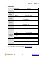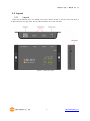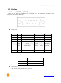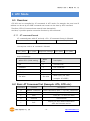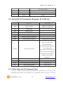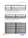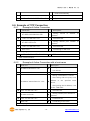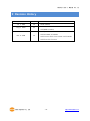
1
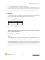
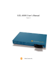
Serial Device Server CSE-H21 User’s Manual Version 1.2 2008-12-04 Sollae Systems Co., Ltd. http://www.sollae.co.kr CSE-H21 User’s Manual Ver. 1.2 To all residents of the European Union Important environmental information about this product This symbol on this unit or the package indicates that disposal of this unit after its lifecycle could harm the environment. Do not dispose of the unit as unsorted municipal waste; it should be brought to a specialized company for recycling. It is your responsibility to return this unit to your local recycling service. Respect your local environmental regulation. If in doubt, contact your local waste disposal authorities Sollae Systems Co., Ltd. -1- http://www.sollae.co.kr CSE-H21 User’s Manual Ver. 1.2 Contents 1 OVERVIEW ...............................................................................................................................- 5 1.1 Overview ................................................................................................................................................................ - 5 1.2 Components ......................................................................................................................................................... - 5 1.3 Specification ......................................................................................................................................................... - 6 1.4 Layout ...................................................................................................................................................................... - 7 - 1.4.1 Layout ............................................................................................................................................................ - 7 1.4.2 LED indicators............................................................................................................................................. - 8 1.4.3 ISP Switch ..................................................................................................................................................... - 8 1.5 Interface ................................................................................................................................................................. - 9 - 1.5.1 RS232 Port (DB9M) .................................................................................................................................. - 9 1.5.2 Ethernet Interface .................................................................................................................................. - 10 1.5.3 Power ........................................................................................................................................................... - 11 2 GETTING START ................................................................................................................... - 12 2.1 Installation Method ........................................................................................................................................ - 12 - 2.1.1 Checking the Communication Environment ............................................................................. - 12 2.1.2 Connecting to the Network .............................................................................................................. - 12 2.1.1 Configuring the Environmental Variables ................................................................................... - 13 2.2 Test Run ............................................................................................................................................................... - 13 - 2.2.1 Changing PC IP Address .................................................................................................................... - 13 2.2.2 Installing CSE-H21 ................................................................................................................................. - 13 2.2.3 Configuring CSE-H21 ........................................................................................................................... - 13 2.2.4 Communication Test ............................................................................................................................. - 15 3 CONFIGURATION ................................................................................................................. - 18 3.1 IP Address and Environmental Variables ............................................................................................. - 18 3.2 Configuring with ezManager ..................................................................................................................... - 18 - 3.2.1 ezManager ................................................................................................................................................ - 18 3.2.2 Buttons of the ezManager ................................................................................................................ - 19 3.2.3 ezManager Configuration Items ..................................................................................................... - 21 3.2.4 ezManager Operation example ...................................................................................................... - 23 3.3 AT command..................................................................................................................................................... - 25 3.4 Setting DHCP .................................................................................................................................................... - 25 3.5 Setting PPPoE ................................................................................................................................................... - 25 4 SYSTEM MANAGEMENT ..................................................................................................... - 26 - Sollae Systems Co., Ltd. -2- http://www.sollae.co.kr CSE-H21 User’s Manual Ver. 1.2 4.1 Operation Mode .............................................................................................................................................. - 26 - 4.1.1 normal mode ........................................................................................................................................... - 26 4.1.2 Serial Configuration Mode ................................................................................................................ - 26 4.1.3 ISP Mode ................................................................................................................................................... - 26 4.1.4 Comparison between two modes.................................................................................................. - 26 4.2 Upgrading new firmware ............................................................................................................................ - 27 4.3 Checking current status ............................................................................................................................... - 27 - 4.3.1 Telnet login ............................................................................................................................................... - 27 4.3.2 Commands for checking the status .............................................................................................. - 27 4.3.3 Check Status in the ezManager ...................................................................................................... - 28 4.4 IP Change Trap ................................................................................................................................................. - 29 - 4.4.1 DDNS – www.dyndns.com ................................................................................................................. - 29 4.4.2 TCP/UDP..................................................................................................................................................... - 29 4.5 Remote Debugging ........................................................................................................................................ - 31 5 COMMUNICATION MODE .................................................................................................. - 32 5.1 Introduction ....................................................................................................................................................... - 32 5.2 T2S ......................................................................................................................................................................... - 33 - 5.2.1 TCP Connection ...................................................................................................................................... - 33 5.2.2 Connection Limitation ......................................................................................................................... - 33 5.2.1 Serial Data Before the TCP Connection ...................................................................................... - 34 5.2.2 Data Transmission ................................................................................................................................. - 34 5.2.3 Disconnection .......................................................................................................................................... - 34 5.3 COD ....................................................................................................................................................................... - 35 - 5.3.1 Serial Data Before the TCP Connection ...................................................................................... - 35 5.3.2 Data Transmission ................................................................................................................................. - 35 5.3.3 Disconnection .......................................................................................................................................... - 36 5.3.4 DNS .............................................................................................................................................................. - 36 5.4 ATC ......................................................................................................................................................................... - 37 5.5 U2S ........................................................................................................................................................................ - 38 6 ATC MODE ............................................................................................................................ - 39 6.1 Overview ............................................................................................................................................................. - 39 - 6.1.1 AT command format ............................................................................................................................ - 39 6.2 Basic AT Command Set (Example: ATA, ATD etc.) ........................................................................... - 39 6.3 Extended AT Commands (Example: AT+PLIP etc.) ........................................................................... - 40 6.4 Online State and AT Command State ................................................................................................... - 40 - 6.4.1 Changing Online State to AT Command State ........................................................................ - 41 6.4.2 Changing AT Command State to Online State ........................................................................ - 41 Sollae Systems Co., Ltd. -3- http://www.sollae.co.kr CSE-H21 User’s Manual Ver. 1.2 6.5 Example of Configuration with AT Command ................................................................................... - 41 6.6 Example of TCP Connection ...................................................................................................................... - 42 - 6.6.1 Example of Active Connection ........................................................................................................ - 42 6.6.2 Example of Active Connection with a host name .................................................................. - 42 6.6.3 Example of passive Connection ...................................................................................................... - 43 6.7 Example of TCP Disconnection ................................................................................................................. - 43 - 6.7.1 Example of active disconnection .................................................................................................... - 43 6.7.2 Example of passive disconnection ................................................................................................. - 43 7 SECURE COMMUNICATION ............................................................................................... - 44 7.1 SSL ......................................................................................................................................................................... - 44 - 7.1.1 SSL (Secure Socket Layer) .................................................................................................................. - 44 7.1.2 How to set the SSL on CSE-H21 .................................................................................................... - 44 7.1.3 Restriction.................................................................................................................................................. - 45 7.2 SSH ........................................................................................................................................................................ - 45 - 7.2.1 SSH (Secure Shell) ................................................................................................................................. - 45 7.2.2 How to set the SSH on CSE-H21 ................................................................................................... - 45 7.2.3 Restriction.................................................................................................................................................. - 46 8 TECHNICAL SUPPORT, WARRANTY, AND NOTES ON OPERATION ........................... - 47 8.1 Technical Support ........................................................................................................................................... - 47 8.2 Warranty .............................................................................................................................................................. - 47 - 8.2.1 Refund......................................................................................................................................................... - 47 8.2.2 Free Repair Services ............................................................................................................................. - 47 8.2.3 Charged Repair Services .................................................................................................................... - 47 8.2.4 Notes on Operation ............................................................................................................................. - 47 9 REVISION HISTORY ............................................................................................................. - 49 - Sollae Systems Co., Ltd. -4- http://www.sollae.co.kr CSE-H21 User’s Manual Ver. 1.2 1 Overview 1.1 Overview Along with the development of the Internet, the demand for data communication functions has increased recently. Data communication over the Internet requires using TCP/IP, the Internet communication protocol. That is to say, in order to connect a system to the Internet, TCP/IP protocol must be implemented. It is possible to implement TCP/IP by directly implementing the protocol, porting public TCP/IP, or using Operating System (OS). However, all these methods impose burdens on the developer in time, cost, and technology. ezTCP series, a Serial ↔ TCP/IP protocol converter product group of Sollae Systems, enables you to use TCP/IP communication (the Internet communication) function simply by “connecting the cable to a serial port”. ezTCP sends data from the serial port to the Internet network after TCP/IP processing, and vice versa. CSE-H21 in ezTCP product group is a product that provides TCP/IP communication through Ethernet. In other words, like other ezTCP products, CSE-H21 sends data from the serial port to the LAN after TCP/IP processing and vice versa. As CSE-H21 has 2 RS232 ports, it can be connected to two RS232 devices in the same time. And it is easy CSE-H21 to attach to user systems because of its compact size. Because it has SSL and SSH function, user can communicate more safely. And it provides DHCP and PPPoE functions, so that it can be applied to the cable network and the xDSL network. And it has DDNS(Dynamic DNS) function, so it can be used more easily in the internet. It can be operated wide range temperature condition and its serial ports are isolated electrically and there is surge protection function on the Ethernet port, so it is very suitable for noisy industrial environment. It also provides debugging function, so user can solve the problem with ours. 1.2 Components CSE-H21 Body CD including utilities and documents (Option) 5V Power Adapter (Option) RS232 cable for PC connection (Option) Sollae Systems Co., Ltd. -5- http://www.sollae.co.kr CSE-H21 User’s Manual Ver. 1.2 1.3 Specification Power Input Voltage 5V (±10%) Current 200mA typical Dimension 158mm x 90mm x 24mm Weight about 340g Interface Serial Port Serial 9 pin Dsub male Network 10/100 Base T (RJ45) 2 x RS232 (300bps ~ 230400bps, RTS/CTS Flowcontrol) Ethernet 10/100 M bit auto-sense Network Auto MDI/MDIX TCP, UDP, IP, ICMP, ARP, DHCP, PPPoE, DNS lookup, DDNS(Dynamic DNS) Protocols Telnet COM Port Control Option(RFC2217) SSL3.0/TLS1.0, SSH Diagnostic Online Debugging Function RoHS RoHS Compliant MIC: SLS-CSE-H21 (A) Approvals CE: F690501/SP-EMY000088 FCC: F690501/RF-EMY002716 Communicati on Mode T2S TCP Server Mode COD TCP Client Mode TCP Server / Client ATC (AT command emulation) U2S Utilities UDP ezManager Configuration utility via LAN Ezterm Socket test utility Hotflash Firmware download utility via TFTP ezVSP Serial-TCP/IP virtual driver for Windows You can download the firmware from our website (http://www.eztcp.com). Sollae Systems Co., Ltd. -6- http://www.sollae.co.kr CSE-H21 User’s Manual Ver. 1.2 1.4 Layout 1.4.1 Layout There are an Ethernet port, two RS232 ports, and a Power socket on the top side. And there is an ISP switch on the right side. And 15 LED indicators are in the CSE-H21. Figure 1-1 CSE-H21 Layout Sollae Systems Co., Ltd. -7- http://www.sollae.co.kr CSE-H21 User’s Manual Ver. 1.2 1.4.2 LED indicators There are 15 LED indicators on the CSE-H21. The left 5 are for LAN status, and the middle and right 5 are for COM1 and COM2 respectively. The followings are the operations of each LED indicators. Table 1-1 LED indicators Name Color LED Status Description PWR Red On Power is on. Blink every 1 IP address is assigned. second L STS Yellow A N C O M 1.4.3 Blink 4 times IP address is net assigned in DHCP or PPPoE every 1 second modes. Off ISP Mode LINK Green On CSE-H21 is connected to the Ethernet. RXD Yellow Blink Ethernet packet is received TXD Green Blink Ethernet packet is transmitted TCP Green On TCP is connected RXD Yellow Blink serial data are received TXD Green Blink serial data are transmitted RTS Green On CTS Yellow On There are enough rooms to receive serial data. CTS signal from the counter-part serial device ISP Switch There is an ISP switch on the side. If this switch is push 20ms~1s, it operates as Serial Configuration Mode. If this switch is push over 1 second, CSE-H21 operates as ISP mode. User can do firmware download to the CSE-H21 in the ISP mode. Please refer to 4.2 for more information on firmware download. Sollae Systems Co., Ltd. -8- http://www.sollae.co.kr CSE-H21 User’s Manual Ver. 1.2 1.5 Interface 1.5.1 RS232 Port (DB9M) There are two RS232 ports. The ports are interfaced with 9 pin D-sub male connectors. The serial ports are isolated electrically. Figure 1-2 9 pin D-sub male connector RS232 ports Table 1-2 RS232 Port Specification Number Name Description level Dir. Etc. 1 DCD Data Carrier Detect RS232 Input optional 2 RXD Receive Data RS232 Input mandatory 3 TXD Transmit Data RS232 Output mandatory 4 DTR Data Terminal Ready RS232 Output optional 5 GND Ground Ground - mandatory 6 DSR Data Set Ready RS232 Input optional 7 RTS Request To Send RS232 Output optional 8 CTS Clear To Send RS232 Input optional 9 RI Ring Indicator RS232 Input optional Data bits, Parity, Stop bit Table 1-3 RS232 Parameters Items Parameters Data bit 8, 7, 6, 5 Parity None, Even, Odd, Mark, Space Stop bit 1, 1.5, 2 Flow Control CSE-H21 has RTS/CTS flow-control function. Sollae Systems Co., Ltd. -9- http://www.sollae.co.kr CSE-H21 User’s Manual Ver. 1.2 Telnet COM Port Control Option CSE-H21 has a Telnet COM Port Control function that is defined in the RFC2217. If this option is set, CSE-H21 transmits serial input signals (CTS, DSR) to the peer host and set the values(RTS, DTR, baud rate, data bits, parity, stop bit) onto its serial ports from the peer host. TX Delay CSE-H21 has a function that delays its serial data for the user‟s slow device. User can set the interval between byte and byte which are outputting from CSE-H21‟s serial ports. Its unit is byte. 1.5.2 Ethernet Interface Network part of CSE-H21 is configured with Ethernet. So, what you have to do is only to connect UTP cable. The Ethernet part detects 10Mbit or 100Mbit Ethernet automatically, to connect the corresponding cable. It also provides auto MDI/MDIX function to detect 1:1 cable or cross-over cable automatically. Each piece of Ethernet equipment has unique hardware addresses, and CSE-H21also has factory-set hardware address (which is called MAC address) Figure 1-3 RJ45 Ethernet connector Table 1-4 Ethernet port pin description Number Name Direction 1 Tx+ Output 2 Tx- Output 3 Rx+ Input 4 - - 5 - - 6 Rx- Input 7 - - 8 - - Sollae Systems Co., Ltd. - 10 - http://www.sollae.co.kr CSE-H21 User’s Manual Ver. 1.2 1.5.3 Power DC5V is used for CSE-H21 and the specification is below: Figure 1-4 DC 5V Power Jack Sollae Systems Co., Ltd. - 11 - http://www.sollae.co.kr CSE-H21 User’s Manual Ver. 1.2 2 Getting Start 2.1 Installation Method You can install CSE-H21 in the following steps. Table 2-1 CSE-H21 Installation steps Title Item 1. Sub-item IP address environment Checking the communication Check items Application program to be used environment 2. Check Connecting to method the network Configuration 3. Serial port parameters method Configuring the Check the LINK LED Set by ezManager, a utility program for configuration through the network. Set by AT commands in ATC mode IP address related items environmental Configuration parameters items Serial port related items Communication mode (depending on application program) 4. Application to the field 2.1.1 Checking the Communication Environment Before installing CSE-H21, check the network environment where CSE-H21 is to be installed, including the followings matters: IP address environment (local IP, subnet mask, gateway, DHCP/PPPoE etc.) Serial port type of the equipment to which CSE-H21 is going to be connected (RS232) Serial port items of the equipment to which CSE-H21 is going to be connected (baud rate, data bit, parity, stop bit, flow control) Application program protocol to be used (TCP/UDP, server/client, etc.) Security Function (SSL, SSH) 2.1.2 Connecting to the Network Connect power to CSE-H21, and connect CSE-H21 either directly to the Ethernet port of the PC where test is to be performed or to the network (hub) to which the PC is connected. Sollae Systems Co., Ltd. - 12 - http://www.sollae.co.kr CSE-H21 User’s Manual Ver. 1.2 2.1.1 Configuring the Environmental Variables When network connection is completed, configure the environmental variables such as IP address related items, serial port related items, and communication mode related items through the LAN using “ezManager” the environmental variable configuration program. . 2.2 Test Run You can perform test run according to the following orders. The test run described here is based on the assumption that the IP address of the PC is set to 10.1.0.2. 2.2.1 Changing PC IP Address You can change the IP address of your PC as follows: IP Address 10.1.0.2 Subnet Mask 255.0.0.0 Gateway IP Address 2.2.2 - Installing CSE-H21 Connect the supplied RS232 cable between your PC and CSE-H21, the LAN cable to the hub to which the PC is connected or directly to the PC, and the supplied CSE-H21 power adapter to CSE-H21 for power supply. If the LAN cable has been correctly connected when power is supplied, LINK LED turns on. 2.2.3 Configuring CSE-H21 Configure CSE-H21 setting using ezManager, the ezTCP configuration program, as follows. Run ezManager, and click [Search ezTCP] button in the ezManager window. And, ezManager program will search all CSE-H21s on the local network. When ezTCP is searched, MAC address of the ezTCP is displayed on the [Search List] window (The MAC address is indicated at the bottom of the product case). Select the corresponding MAC address, and set the same as shown in the following figure and click [Write] button to save the settings. When no ezTCP is found, check the Windows firewall. If you press [Firewall] button in the ezManager, you can see the Windows Firewall menu more easily Sollae Systems Co., Ltd. - 13 - http://www.sollae.co.kr CSE-H21 User’s Manual Ver. 1.2 Figure 2-1 Initial settings Sollae Systems Co., Ltd. - 14 - http://www.sollae.co.kr CSE-H21 User’s Manual Ver. 1.2 2.2.4 Communication Test 1) A program for testing starts if you press the [ezTCP Test] button of the ezManager. Figure 2-2 The window of the Test Program 2) Press the [Connect] button after inputting 10.1.0.1 and 1470 in the IP and Port. If the TCP connection is established there will be “Connected [REMOTE HOST 10.1.0.1 : 1470]. And the STS of COM1 will be on. ① ② ③ Figure 2-3 A window to test Sollae Systems Co., Ltd. - 15 - http://www.sollae.co.kr CSE-H21 User’s Manual Ver. 1.2 3) Press the [Open] button after selecting serial port that is connected to the CSE-H21. If the serial port is open, the “COM1 Port is opened” message will be shown. ⑤ ④ Figure 2-4 the screenshot of test program 4) If you press the [Send] button below of the [LAN TX] window, the data in the [LAN TX] window will be transmitted to the [Serial RX]. ⑥ ⑦ Figure 2-5 The data are transmitted to the [Serial RX] window Sollae Systems Co., Ltd. - 16 - http://www.sollae.co.kr CSE-H21 User’s Manual Ver. 1.2 5) If you press the [Send] button below the [Serial TX] window, the data will be transmitted from the [Serial TX] window to the [LAN RX] Window. ⑨ ⑧ Figure 2-6 The data are transmitted to the [LAN RX] window 6) If the transmitting and receiving data are same, the communication test is successful. Sollae Systems Co., Ltd. - 17 - http://www.sollae.co.kr CSE-H21 User’s Manual Ver. 1.2 3 Configuration 3.1 IP Address and Environmental Variables For TCP/IP communication, you must set IP address related items. In addition, you have to set serial port related items (serial port type, communication speed, data bit length, parity bit, flow control, etc) to CSE-H21. You can set the IP address and the serial port related items by using ezManager, the supplied configuration utility which allows you to configure your CSE-H21 over the network, or by using AT commands in ATC mode 3.2 Configuring with ezManager 3.2.1 ezManager The basic environmental variables (IP address related items, serial port items, and etc.) can be set by ezManager which is an integrated management tool for Windows. The ezManager is operated in Microsoft Windows(Windows 98, 98 SE, 2000 Pro, ME, XP Pro/Home, Vista). Following is the screen shot of ezManager which is just launched. Figure 3-1 the initial window of the ezManager Sollae Systems Co., Ltd. - 18 - http://www.sollae.co.kr CSE-H21 User’s Manual Ver. 1.2 3.2.2 Buttons of the ezManager To set the CSE-H21, ezManager communicates with the CSE-H21 through UDP broadcast. The ezManager identify with the CSE-H21‟s MAC LOCAL address. So user can configure the CSE-H21 even though user doesn‟t know its IP address or the IP address isn‟t set to it. User can configure CSE-H21 which is inside of router(within local network). The UDP port number that is used is 50005. REMOT E The ezManager communicates with the CSE-H21 through UDP unicast with IP address. So user can configure the CSE-H21 which is outside of the local network. The UDP port number that is used is 50005. The ezManager use PC‟s COM Port(RS232 port) when it configures the SERIAL CSE-H21. So user has to connect PC‟s COM port to COM1 port of the CSE-H21. And the CSE-H21 should be in the Serial Configuration Mode. Searches all CSE-H21 on user local network. The result is displayed on Search the [Search List] box. Each value represents each ezTCP‟s MAC address. ezTCP And parameters of the selected ezTCP are displayed in the right window. (The MAC address of CSE-H21 is on the bottom of its case.) If user inputs the MAC address of the CSE-H21 into the MAC address input box in the [LOCAL] tab or inputs the IP address of the CSE-H21 into Read the [REMOTE] tab and presses [Read] button, then user can read only the CSE-H21‟s parameters. If there are a lot of ezTCPs in the network so it is hard to find the ezTCP, it is very useful. Write Change PWD Stores the modified parameters by pressing the [Write] button. The CSE-H21 resets automatically if the [Write] button is pressed. This button is for setting or modifying the password of CSE-H21. If a password of the CSE-H21, user has to input the password in the text box of the ezManager when user sets parameters of the CSE-H21. User can read the current status of the CSE-H21 by pressing this Status button. If user presses this button, a new window is appeared and some information will be shown. (the running time, IP addresses, the amount of receiving and transmitting from/to the serial ports. User can debug CSE-H21. If the [Debug] option of the [OPTION] tab is set and user presses this button, user can debug CSE-H21. When the Debug debugging function is running, CSE-H21 broadcasts debugging data to Message the - 19 -thernet with UDP 50006. So user has to open the UDP 50006 port to debug CSE-H21. After debugging, user has to unset [Debug] option of the [OPTION] tab to prevent heavy network traffic. Sollae Systems Co., Ltd. - 19 - http://www.sollae.co.kr CSE-H21 User’s Manual Ver. 1.2 Firewall ezTCP ezManger would not work if any firewall functions are working. This button is a shortcut to the [Windows Firewall]. You can simply test ezTCP‟s function in terms of both serial and Test Export to network ports with this button. You can save the environmental variables in the screen to a file with file Import this button. You can load the environmental variable from the file that you have from file Multiple saved. You can save same environmental variables to multiple ezTCP‟s with Setting PING/ARP this button. User can do ping-tests with this button. And user can check or delete the ARP cache table of the PC. Initialize User can initialize the CSE-H21 with this button. ENV Searches all CSE-H21 on user local network. The result is displayed on Search the [Search List] box. Each value represents each ezTCP‟s MAC address. ezTCP And parameters of the selected ezTCP are displayed in the right window. (The MAC address of CSE-H21 is on the bottom of its case.) Exit Sollae Systems Co., Ltd. Terminating ezManager. - 20 - http://www.sollae.co.kr CSE-H21 User’s Manual Ver. 1.2 3.2.3 ezManager Configuration Items NETWORK Network Local IP Address CSE-H21‟s IP address Subnet Mask Subnet Mast Gateway IP Address Gateway‟s IP address Option DNS IP Address Name Server‟s IP address DHCP Decide whether to receive CSE-H21 IP address via DHCP PPPoE Decide whether to receive CSE-H21 IP address via PPPoE PPPoE ID & Password ARP Obtain DNS server address automatically ID and Password that will be used in PPPoE ARP Function activation status (Conditionally required for DHCP) If CSE-H21‟s IP address is set as a dynamic IP (DHCP or PPPoE), it will automatically receive DNS server address. If this check box is not activated, the IP address designated in the [DNS IP Address] will be used as the DNS server address. IP Change Trap Protocol IP Change Trap Method Interval The interval to send IP information DDNS ID DDNS PWD The user account which was registered to the service provider (If DDNS is selected) The password of user account which was registered to the service provider (If DDNS is selected) Port No TCP or UDP Port number to send (If TCP or UDP is selected) Data Type TCP or UDP IP address to send (If TCP or UDP is selected) Host Name The host name of the CSE-H21 (example: eztcp.dyndns.com) INTERFACE Serial Type Fixed to RS232 Baudrate Baudrate of the serial port(1,200 ∼ 230,400bps) Data bits The length of the serial port(5, 6, 7, 8 bits) Parity Parity (NONE, EVEN, ODD, MARK, SPACE) Stop bit Stop bit (1, 1.5, 2 bits) Sollae Systems Co., Ltd. - 21 - http://www.sollae.co.kr CSE-H21 User’s Manual Ver. 1.2 Flow Control TX Delay Flow control (NONE, RTS/CTS) The interval between byte and byte which is outputting from the CSE-H21. (Unit: 1 byte) ezTCP Mode Communication Mode Local Port Port number for waiting to be connected in Server mode Peer Address IP address or host name to connect in Client mode Peer Port Port number to connect in Client mode Byte Count Minimum number of bytes attempting to connect/transmit Data amount before the TCP connection Timeout Time out When CSE-H21 sends data from its serial port to the ethernet, the [Guard Time] is a unit between two packets. Guard Time If there is no data from its serial port during the specified [Guard Time], CSE-H21 sends data to ethernet. (unit: 10ms, minimum vale: 4 (40ms)) If the Telnet COM Port Control Option is enabled, CSE-H21 sends Telnet COM port control option the CTS, DSR control signal to the communication counter part, and CSE-H21 sets its serial port items(RTS, DTR, Baudrate, databits, parity, stop bit) after getting information from the communication counter part. OPTION Remote Search Enable/disable [REMOTE] tab of ezManager Telnet Enable/disable telnet Enable/disable the remote debugging function of CSE-H21 Debug After debugging, user has to disable this function to reduce network load. SSL Enable/disable the SSL function SSH Enable/disable the SSH function Comments User specific information Allowed Ethernet Address Allowed IP Sollae Systems Co., Ltd. The only host that has specified Ethernet address(MAC address) can access the CSE-H21 The only host that has specified IP address range can - 22 - http://www.sollae.co.kr CSE-H21 User’s Manual Ver. 1.2 access the CSE-H21 If this parameter is set, CSE-H21 replies to the only host that has ezManager Lock parameters that is defined in the [Allowed Ethernet Address] or [Allowed IP]. 3.2.4 ezManager Operation example ezManager can be used to change the IP address related items, the serial port setup value, the serial port operation mode, and how to setup ezTCP. This section describes these functions briefly. For more information, see the following sections. The following example shows how to read and change ezTCP‟s basic functions. Try changing ezTCP setup value according to the following sequence: . When the ezTCP power is turned on and the LAN cable is connected correctly, pressing [Search ezTCP] or [Read] button will display the following window: Figure 3-2 Searching ezTCP If a network-attached ezTCP is detected, the following message will be displayed. If a message pops up indicating that there is no response from ezTCP, check that the power is turned on and the cable is connected correctly or make sure the firewall function on your PC, then try pressing [Search] or [Read] button. (The protocol that ezManager uses is UDP and its port is 50005. And its debugging port is 50006.) Figure 3-3 ezTCP is found If more than one ezTCP are detected, ezTCP‟s MAC ADDRESS will be displayed in the [Search List] box on ezManager. Check if the MAC ADDRESS displayed in the [Search List] window corresponds to that printed on ezTCP main body. Sollae Systems Co., Ltd. - 23 - http://www.sollae.co.kr CSE-H21 User’s Manual Ver. 1.2 Figure 3-4 search result of ezTCP Set [ezTCP Mode], [Local IP Address], [Local Port], and serial port related items. After setting press [Write] button. Pressing the [PING / ARP] button of the ezManager, a [PING / ARP] window will be shown. You can ping test in this window. The following is a screenshot that ithe ping test is OK. Sollae Systems Co., Ltd. - 24 - http://www.sollae.co.kr CSE-H21 User’s Manual Ver. 1.2 Figure 3-5 ping test when the IP address is 10.1.0.1 3.3 AT command In ATC mode, the user can set environment variables through the serial port using AT command. For more information, See “7. ATC Mode”. 3.4 Setting DHCP Under environment with a network operating a DHCP server, DHCP protocol allows the user to automatically set the IP address, subnet mask, gateway, and name server of ezTCP. Using DHCP automatic setup function requires the user to check [DHCP] item on ezManager. Note that the user may have to check [ARP] item according to the type of DHCP servers. 3.5 Setting PPPoE PPPoE is used in most ADSL and VDSL. To use PPPoE function, PPPoE function should be enabled and PPPoE ID and PPPoE password should be configured. The local IP address of CSE-H21 is assigned automatically in PPPoE environment. √ Some ADSL or VDSL modem use DHCP. Please contact your ISP (Internet Service Provider). Sollae Systems Co., Ltd. - 25 - http://www.sollae.co.kr CSE-H21 User’s Manual Ver. 1.2 4 System Management 4.1 Operation Mode CSE-H21 can operate in one of two modes (normal and ISP modes). Normal mode is ordinary data communication mode; and ISP mode is used to download CSE-H21 firmware through the Ethernet port. 4.1.1 normal mode The normal mode is an operation mode that CSE-H21‟s works for normal purposes. If CSE-H21 boots up without any other treatment, it works in the normal mode. Please refer to the 5. Normal Mode. 4.1.2 Serial Configuration Mode If you press the switch on the side of the body in the normal mode for 20ms ~ 1s, it works in the Serial Configuration Mode. You can set the environmental variables through the COM1 port in this mode. 4.1.3 ISP Mode If you press the switch on the side of the body in the normal mode over 1 second, it works in the ISP mode. You can download new firmware to CSE-H21 with hotflash program that is a TFTP client through the Ethernet. 4.1.4 Comparison between two modes The following is a comparison between the normal mode and the ISP mode. Table 4-1 Operation Mode Mode How to initiate Description Baudrate Normal data normal Power on CSE-H21 without pressing communication the value that the ISP button mode user set T2S, ATC, COD, U2S Serial Config uratio Configuring CSE- 115200bps/N/ H21 through COM1 8/1 Pressing the ISP button over 1 Firmware download 115200bps/N/ second mode 8/1 Pressing the ISP button for 20ms~1s. n ISP Sollae Systems Co., Ltd. - 26 - http://www.sollae.co.kr CSE-H21 User’s Manual Ver. 1.2 4.2 Upgrading new firmware You can download new firmware of CSE-H21 in the ISP mode. You have to connect the Ethernet ports of you PC and CSE-H21 to your network in advance. The method is followed: . Press ISP button more than 100m seconds. Then it works at the ISP mode. All LED except PWR LED and LINK LED will be off in the ISP mode. Run hotflash program that is supplied by Sollae Systems. And then, input IP address of CSE-H21 and select a new firmware to download by pressing the [FILE] menu. And press the [SEND] button. You have to uncheck the [Verify firmware version] in this case. Figure 4-1 A firmware is downloading to the CSE-H21 with the hotflash After completing the download, the following message will be shown. And CSE-H21 boots up automatically and works at the normal mode. Figure 4-2 Completing firmware download with hotflash 4.3 Checking current status 4.3.1 Telnet login You can log in the CSE-H21 if you enable the [Telnet option] in the [OPTION] tab of the ezManager. Then you can check the network and serial status after logging in the CSE-H21. If you press “telnet [CSE-H21‟s IP address]” on the command prompt of Windows, you can log in CSEH21 4.3.2 Commands for checking the status Network Status Sollae Systems Co., Ltd. - 27 - http://www.sollae.co.kr CSE-H21 User’s Manual Ver. 1.2 If you type “st net”, you can check the network status of CSE-H21. Figure 4-3 The network status Serial ports‟ status If you type “st sio”, you can check the serial ports‟ status of CSE-H21 The tx_count and rx_count is the total bytes since the CSE-H21 has booted up. Figure 4-4 The serial status 4.3.3 Check Status in the ezManager If you press the [STATUS] in the ezManager, you can monitor the current status of CSE-H21. If you set the [Status Request] button, the information will be updated every pre-specified time And user can close the TCP connection in the TCP/IP Connection window with mouse-right button. Sollae Systems Co., Ltd. - 28 - http://www.sollae.co.kr CSE-H21 User’s Manual Ver. 1.2 Figure 4-5 A screen shot of the [STATUS] window 4.4 IP Change Trap CSE-H21 has a function to send its IP address. So user can solve the problem that IP address is changed automatically in the dynamic IP address environment. CSE-H21 supports 3 kinds of transmitting methods – DDNS with DynDNS, TCP and UDP. 4.4.1 DDNS – www.dyndns.com DDNS(Dynamic DNS) is a system that communicates by the hostname that is registered to a DNS server after registering the IP address in the dynamic IP address environment. The DDNS function that is supplied by CSE-H21 is that CSE-H21 registers its IP address to the DynDNS Inc.(www.dyndns.com)‟s DNS server. So user has to register user name and hostname to the website of the DynDNS to use the DDNS function. 4.4.2 TCP/UDP CSE-H21 sends its IP information to the pre-defined a TCP or UDP server periodically. So user has to set the server‟s IP address and port number to use this function in advance. CSE-H21 supports both ASCII and BINARY mode. ASCII message format is followed: Each byte of the ethernet address is divided by colons, so the total byes of the ethernet address is 17bytes. The IP address is the CSE-H21‟s IP address that is assigned to the CSE-H21. The product information is composed by 2 bytes-product ID and 6 bytes-firmware version. For example: “11010106” means that product ID is 0x11 and the firmware version is 1.1G. The comments is the [Comments] field in the [OPTION] tab in the ezManager. Each message of the ASCII data is divided by 0x0d0a. Sollae Systems Co., Ltd. - 29 - http://www.sollae.co.kr CSE-H21 User’s Manual Ver. 1.2 1 2 3 4 5 6 7 8 Ethernet Address 0x0d 0x0a IP Address 0x0d 0x0a Product Information 0x0d 0x0a Comment 0x0d 0x0a Figure 4-6 ASCII Message Format The BINARY message format ends with 0x00. The message format of BINARY is followed: 1 len 2 3 cm_len 4 5 6 7 8 Ethernet address IP address p_id major minor Rev Comment 0x00 Figure 4-7 Binary Message Format - len : total length - cm_len : comment length - p_id : product ID - major / minor / Rev : firmware version Sollae Systems Co., Ltd. - 30 - http://www.sollae.co.kr CSE-H21 User’s Manual Ver. 1.2 4.5 Remote Debugging If the [Debug] field in the [OPTION] tab of the ezManager, CSE-H21 transmits debugging messages with UDP port 50006. Then user can get the messages with new window if user presses [Debug Message] button as followed: Figure 4-8 Debugging screen This function is very useful when there are any problems when user installs the CSE-H21 in the user site. Sollae Systems Co., Ltd. - 31 - http://www.sollae.co.kr CSE-H21 User’s Manual Ver. 1.2 5 Communication Mode 5.1 Introduction Normal communication mode is suitable for the purpose of using CSE-H21. Normal communication mode can be classified into four modes – T2S, ATC, COD, and U2S – each of which is described in the following table. Table 5-1 Communication Mode Communic ation Need for user Protocol Connection Mode Equipment Software Modification T2S TCP ATC TCP COD TCP U2S UDP Passive Connection Topolo variable via serial gy port Impossible 1:1 Needed Possible 1:1 Not needed Impossible 1:1 Not needed Impossible N:M Passive No environmental Not needed Active Active Configuring TCP protocol requires connection process. The connection is always established as 1:1 connection. At this time, the host waiting for connection (passive connection) is called a server and the one attempting to connect (active connection) is called a client. On the other hand, UDP communicates by block unit without connection process. As UDP does not require connection, numbers of hosts can communicate at the same time. Sollae Systems Co., Ltd. - 32 - http://www.sollae.co.kr CSE-H21 User’s Manual Ver. 1.2 5.2 T2S In T2S mode, the CSE-H21 functions as a server. When a host connects to predefined local port, the CSE-H21 accepts a TCP connection. When the ezTCP accepts TCP connection, then the TCP connection is established. After connection is established, TCP/IP processing is performed on the data coming to the serial port, which is then transmitted to the remote host. And the TCP/IP data coming from the remote host is TCP/IPprocessed and transmitted to the serial port to establish data communication. Remote Host ezTCP Serial Device Listen on local port Request TCP co nnection ection Accept TCP conn ack connected DATA “ABC” DATA “ABC” (TCP/IP) DATA “DEF” (TCP/IP) DATA “DEF” <T2S Mode> Figure 5-1 T2S Mode 5.2.1 TCP Connection If a host connects to the pre-defined [Local Port] of CSE-H21, the host can communicate bi-directionally. 5.2.2 Connection Limitation CSE-H21 has two connection limitation functions. Those can be set by the [Option] tab of the ezManager. Allowed Ethernet Address If user sets the [Allowed Ethernet Address], the only specified host can access the CSE- H21. Allowed IP When the [Allowed IP] is set, the only hosts that are specified by [Allowed IP] and [Net Mask] can connect to the CSE-H21 Sollae Systems Co., Ltd. - 33 - http://www.sollae.co.kr CSE-H21 User’s Manual Ver. 1.2 Table 5-2 An Example of Allowed IP Allowed IP Net Mask The hosts which can connect 10.1.0.1 255.0.0.0 10.1.0.1 ∼ 10.255.255.254 10.1.0.1 255.255.255.0 10.1.0.1 ∼ 10.1.0.254 192.168.1.4 255.255.255.255 192.168.1.4 5.2.1 Serial Data Before the TCP Connection If the [Byte Count] is 0, all data from the CSE-H21‟s serial port before the TCP connection are ignored. If the [Byte Count] is over 0, CSE-H21 stores serial data to its memory and it transmits these data when CSE-H21 is connected. 5.2.2 Data Transmission Once TCP connection is established, hosts can communicates with the CSE-H21 bidirectionally. And CSE-H21 gathers data from its serial ports. It transmits data when there‟s no data during the specified in the [Guard Time]. If the [Guard Time] is 0, it transmits as soon as it receives data from the serial port. The unit of the [Guard Time] is 10ms. And minimum time is 40ms so minimum guard time is 4(except 0). 5.2.3 Disconnection CSE-H21 disconnects the TCP connection if there is no data transmission during the [Timeout]. The unit of the [Timeout] is a second. Sollae Systems Co., Ltd. - 34 - http://www.sollae.co.kr CSE-H21 User’s Manual Ver. 1.2 5.3 COD In COD mode, the ezTCP functions as a client. When data of the pre-specified size [Byte Count] comes to the serial port, the ezTCP attempts a TCP connection to the TCP port [Peer Port] of the preset host IP [Peer IP Address]. If the remote host accepts the TCP connection, TCP connection will be established. Data coming to the serial port after connection establishment is TCP/IP-processed and transmitted to the remote host. And, data coming from the remote host is TCP/IP-processed and transmitted to the serial port for data communication. Remote RemoteHost Host ezTCP Listen Serial Device DATA “AB” Request TCP con DATA “C” nection Accept TCP con nection Ack connected DATA “ABC” (TCP/IP) DATA “DEF” DATA “DEF” (TCP/IP) DATA “GHI” (TCP/IP) DATA “GHI” <COD connection sequence – Byte Count: 3> Figure 5-2 COD Mode 5.3.1 Serial Data Before the TCP Connection If the [Byte Count] is 0, all data from the CSE-H21‟s serial port before the TCP connection are ignored. If the [Byte Count] is over 0, CSE-H21 stores serial data to its memory and it transmits these data when CSE-H21 is connected. 5.3.2 Data Transmission Once TCP connection is established, hosts can communicates with the CSE-H21 bidirectionally. And CSE-H21 gathers data from its serial ports. It transmits data when there‟s no data during the specified in the [Guard Time]. If the [Guard Time] is 0, it transmits as soon as it receives data from the serial port. The unit of the [Guard Time] is 10ms. And minimum time is 40ms so minimum guard time is 4(except 0). Sollae Systems Co., Ltd. - 35 - http://www.sollae.co.kr CSE-H21 User’s Manual Ver. 1.2 5.3.3 Disconnection CSE-H21 disconnects the TCP connection if there is no data transmission during the [Timeout]. The unit of the [Timeout] is a second. 5.3.4 DNS If numeric IP address is set to the [Peer Address], CSE-H21 tries to connect to the specified IP address. If the alphabetic hostname is set to the [Peer Address], CSE-H21 queries to the DNS server. After CSE-H21 gets the IP address from the DNS server, it tries to connect the IP address. When CSE-H21 is in DHCP or PPPoE mode and the [Obtain DNS server address automatically] is set, CSE-H21 use the DNS server that it gets DNS server IP address during the DHCP or PPPoE connection. Sollae Systems Co., Ltd. - 36 - http://www.sollae.co.kr CSE-H21 User’s Manual Ver. 1.2 5.4 ATC In ATC mode, the user can control the CSE-H21 in a similar way to controlling the modem using AT command. In ATC mode, only a TCP connection is possible and both the server and the client can be configured. In ATC mode, the AT command allows the user to set environment variables including the IP address and control TCP connection and disconnection. Figure 5-3 ATC Mode Refer to “6. ATC Mode” Sollae Systems Co., Ltd. - 37 - http://www.sollae.co.kr CSE-H21 User’s Manual Ver. 1.2 5.5 U2S U2S mode allows for UDP communication. In UDP mode, data are transmitted in blocks, which requires dividing data coming to the serial port into blocks before transmitting data. A procedure for dividing data into blocks is as follows: If data of pre-specified bytes [Byte Count] come to the serial port of the ezTCP or if there is no data during the specified period of time [Timeout], all data received for the same period are recognized as one block which is then transmitted to the UDP. The [Timeout] unit is 10ms. Since UDP communication does not require a connection procedure, the user can establish Nto-M communication via multicast and broadcast. Remote Host ezTCP Serial Device “AB” DATA “ABC” (UDP) 5ms “C” “A” DATA “A” (UDP) 10ms “BC” 9ms DATA “BCA” (UDP) “A” <U2S Transmission sequence – Byte Count:3, Guard Time: 1> Figure 5-4 U2S Mode Sollae Systems Co., Ltd. - 38 - http://www.sollae.co.kr CSE-H21 User’s Manual Ver. 1.2 6 ATC Mode 6.1 Overview CSE-H21 can be controlled by AT commands in ATC mode. For example, the peer host IP address can be set by AT+PRIP command and connect to the host by ATD command. Therefore, CSE-H21 communicates several hosts alternatively. And also, it provides passive connection function by ATA command. 6.1.1 AT command format AT commands start with AT, and end <CR>. AT command format is followed. AT Command <CR>(0x0d) The response code to AT command is followed. <CR>(0x0d) <LF>(0x0a) Response message <CR>(0x0d) <LF>(0x0a) Response Message When ATV1 (initial setting) When Description ATV0 OK 0 command OK CONNECT 1 TCP connected NO CARRIER 3 TCP disconnected ERROR 4 Command error Set value Set value When query set value (example: AT+PRIIP?) 6.2 Basic AT Command Set (Example: ATA, ATD etc.) Command Function A passive connection D active connection E echo H off-hook I Info Sollae Systems Co., Ltd. Description Listen connection (host → CSE-H21 connection) Connecting to host form CSE-H21 Echo (E0 – no echo, E1-echo) disconnection Output CSE-H21 related-information ATI3: the firmware version - 39 - http://www.sollae.co.kr CSE-H21 User’s Manual Ver. 1.2 ATI7: MAC address O Online To online mode V enable result code Result code (numeric-V0, alphabetic-V1) Z reset Reset 6.3 Extended AT Commands (Example: AT+PLIP etc.) Command Function +PLIP local IP address +PSM subnet mask +PGIP default router +PLP listening TCP port +PTO timeout +PRIP Remote machine IP address +PNIP Name Server IP Address Description Needed AT+PWP after setting this parameter Setting Name server IP Setting the peer host name to connect with double quotation. (at+prhn=”www.sollae.co.kr”) +PRHN Remote Host Name After setting this parameter, CSE-H21 queries the IP address according to the name, and set the IP address to the +PRIP parameter. +PRP Remote machine TCP port +PWP Write configuration Saving and Reset +PARP ARP setting function enable/disable ON: 1, OFF: 0 +PDC DHCP enable/disable ON: 1, OFF: 0 6.4 Online State and AT Command State It is AT command mode during disconnected. AT commands can be used in AT command mode. After TCP connection, AT commands cannot be used. To use AT Sollae Systems Co., Ltd. - 40 - http://www.sollae.co.kr CSE-H21 User’s Manual Ver. 1.2 commands during the connection, change state to AT command state. During TCP disconnected, AT commands can be used AT Command State To use AT commands during the connection, required escape sequence During TCP connected, all serial data to CSE-H21 convert Online State TCP and send to ethernet 6.4.1 Changing Online State to AT Command State To change online state to AT command state during the connection, +++ string should be transmitted to CSE-H21 as following time interval. When transmitting +++ string to CSE-H21, +++ string will be sent to peer host. The time from final data the first „+‟ data No data over 500ms(guard time) of „+++‟ string time intervals between „+‟s 0~500ms Time interval after receiving last „+‟ No data over 500ms (guard time) 6.4.2 Changing AT Command State to Online State If CSE-H21‟s state is in AT command state during TCP connection, CSE-H21‟s state can be changed into online state by an ATO command. 6.5 Example of Configuration with AT Command Serial Port Description AT+PLIP=192.168.1.200<CR> ◀ ▶ <CR><LF>OK<CR><LF> Command OK AT+PGIP=192.168.1.254<CR> ◀ ▶ <CR><LF>OK<CR><LF> ▶ <CR><LF>OK<CR><LF> ▶ <CR><LF>OK<CR><LF> ▶ <CR><LF>OK<CR><LF> Setting TIME OUT Command OK AT+PWP<CR> Sollae Systems Co., Ltd. Setting LOCAL PORT Command OK AT+PTO=10<CR> ◀ Setting SUBNET MASK Command OK AT+PLP=1470<CR> ◀ Setting GATEWAY IP address Command OK AT+PSM=255.255.255.0<CR> ◀ Setting LOCAL IP address ▶ - 41 - Saving setting value to EEPROM http://www.sollae.co.kr CSE-H21 User’s Manual Ver. 1.2 Reset automatically ◀ <CR><LF>OK<CR><LF> Command OK ◀ <CR><LF>NO CARRIER<CR><LF> System Reset 6.6 Example of TCP Connection 6.6.1 Example of Active Connection Serial Port Description AT+PRIP=192.168.1.201<CR> ◀ ▶ <CR><LF>OK<CR><LF> remote IP address to connect Command OK AT+PRP=1470<CR> ◀ Setting ▶ <CR><LF>OK<CR><LF> Setting remote port number to connect Command OK ATDT<CR> ▶ Connecting to the host Attempting to connect to the host ◀ <CR><LF>CONNECT<CR><LF> TCP connection success Data Communication 6.6.2 Example of Active Connection with a host name Serial Port Description AT+PNIP=168.126.63.1<CR> ◀ ▶ <CR><LF>OK<CR><LF> Setting name server S IP address Command OK Setting a hostname to connect After setting CSE-H21 query an IP AT+PRHN=”www.sollae.co.kr”<CR> ▶ address to the specified name server. After getting the IP address, it set to the +PRIP field. ◀ <CR><LF>OK<CR><LF> AT+PRP=1470<CR> ◀ Command OK ▶ connect Command OK <CR><LF>OK<CR><LF> ATDT<CR> Setting remote port number to ▶ Connecting to the host Attempting to connect to the host Sollae Systems Co., Ltd. - 42 - http://www.sollae.co.kr CSE-H21 User’s Manual Ver. 1.2 ◀ TCP connection success <CR><LF>CONNECT<CR><LF> Data Communcation 6.6.3 Example of passive Connection Serial Port Description AT+PLP=1470<CR> ◀ ▶ Set LOCAL PORT to listen <CR><LF>OK<CR><LF> Command OK ATA<CR> ▶ Passive connection command Listen on local port from a host A host connects to CSE-H21 ◀ <CR><LF>CONNECT<CR><LF> TCP connection OK Data Communication 6.7 Example of TCP Disconnection 6.7.1 Example of active disconnection CSE-H21 disconnects the connection. Serial Port Description Data Communication(during TCP connection) [guard time]+++[guard time] ◀ ▶ Changing online state to AT command state <CR><LF>OK<CR><LF> ATH ◀ Changed to AT command state ▶ 6.7.2 <CR><LF>OK<CR><LF> TCP disconnection command Command OK Example of passive disconnection The remote host disconnects the connection. Serial Port Description Data Communication(during TCP connection) The remote host disconnect the connection ◀ <CR><LF>NO CARRIER<CR><LF> Sollae Systems Co., Ltd. - 43 - TCP disconnected http://www.sollae.co.kr CSE-H21 User’s Manual Ver. 1.2 7 Secure Communication 7.1 SSL 7.1.1 SSL (Secure Socket Layer) SSL is cryptographic protocol that provides secure communication on the Internet. The SSL works over TCP. 7.1.2 How to set the SSL on CSE-H21 To works for SSL, you have to set the SSL-related parameters as the following steps. Set the [SSL] check box in the ezManager. Log in the CSE-H21 with telnet clinet. Generate an RSA key with a command. CSE-H21 supports 512, 768, and 1024 length keys. Command Format: rsa keygen [key length] Make a certificate with a „cert new‟ command. The certificate is a self signed. Sollae Systems Co., Ltd. - 44 - http://www.sollae.co.kr CSE-H21 User’s Manual Ver. 1.2 Save the parameters for SSL with a „ssl save aa55cc33‟ command. 7.1.3 Restriction To use the SSL with CSE-H21, there is a restriction. You can use only one serial port(COM1) if you set the SSL function. 7.2 SSH 7.2.1 SSH (Secure Shell) SSH is a network protocol that allows secure communications between two devices. You can use this function if your device is a serial port for console and you need secure communication. 7.2.2 How to set the SSH on CSE-H21 To works for SSL, you have to set the SSH-related parameters as the following steps. Set the [SSH] check box in the ezManager. Log in the CSE-H21 with telnet clinet. Generate an RSA key with a command. CSE-H21 supports 512, 768, and 1024 length keys. Sollae Systems Co., Ltd. - 45 - http://www.sollae.co.kr CSE-H21 User’s Manual Ver. 1.2 Command Format: rsa keygen [key length] Generate a DSA key with a „dsa keygen‟. . Set a username and a password to log in with a „ssh id‟ command for the SSH. Save the parameters for SSH with a „ssh save aa55cc33‟ command. 7.2.3 Restriction To use the SSH function with CSE-H21, there is a restriction. You can use only T2S mode (TCP Server mode) if you set the SSH function. Sollae Systems Co., Ltd. - 46 - http://www.sollae.co.kr CSE-H21 User’s Manual Ver. 1.2 8 Technical Support, Warranty, and Notes on Operation 8.1 Technical Support If you have any question regarding operation of the product, visit Customer Support FAQ corner and the message board on Sollae Systems‟ web site or send us an email at the following address: [email protected] Website Address for Customer Support: http://www.sollae.co.kr/Support/index.html 8.2 Warranty 8.2.1 Refund Upon the customer‟s request to refund the product within two weeks after purchase, Sollae Systems will refund the product. 8.2.2 Free Repair Services For product failures occurring within one year after purchase, Sollae Systems provides free repair services or exchange the product. However, if the product failure is due to user‟s fault, repair service fees will be charged or the product will be replaced at user‟s expense. 8.2.3 Charged Repair Services For product failures occurring after the warranty period (one year) or resulting from user‟s fault, repair service fees will be charged and the product will be replaced at user‟s expense. 8.2.4 Notes on Operation Sollae Systems is not responsible for product failures occurring due to user‟s alternation of the product. Specifications of the product are subject to change without prior notice for performance improvement. Sollae Systems does not guarantee successful operation of the product if the product Sollae Systems Co., Ltd. - 47 - http://www.sollae.co.kr CSE-H21 User’s Manual Ver. 1.2 was used under conditions deviating from the product specifications. Reverse engineering of firmware and applications provided by Sollae Systems is prohibited. Use of firmware and applications provided by Sollae Systems for purposes other than those for which they were designed is prohibited. Do not use the product in an extremely cold or hot place or in a place where vibration is severe. Do not use the product in an environment in which humidity is high or a lot of oil exists. Do not use the product where there is caustic or combustible gas. Sollae Systems does not guarantee normal operation of the product under the conditions a lot of noise exists. Do not use the product for a purpose that requires exceptional quality and reliability relating to user‟s injuries or accidents – aerospace, aviation, health care, nuclear power, transportation, and safety purposes. Sollae Systems is not responsible for any accident or damage occurring while using the product.. Sollae Systems Co., Ltd. - 48 - http://www.sollae.co.kr CSE-H21 User’s Manual Ver. 1.2 9 Revision History Date Version Jun. 3. 2008 1.0 Aug. 1. 2008 1.1 Comments Initial Release Add SSL and SSH functions Add WEEE notation Modify ISP button function Dec. 4. 2008 1.2 Add AT+PNIP, AT+PRHN Add Connect with a host name in ATC Mode Add Close TCP function Sollae Systems Co., Ltd. - 49 - http://www.sollae.co.kr