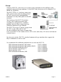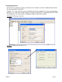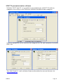
1
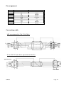
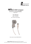
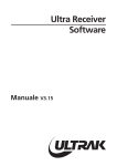
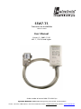
SSW7-TS
Teleservice via the MPI-Bus
700-751-8VK21
User Manual
Version: 3 / 2005-11-29
HW: 1 / FW 3.0 and higher
Order number of manual: 900-751-8VK21/en
Systeme Helmholz GmbH z Hannberger Weg 2 z D-91091 Großenseebach
Phone: +49 9135 7380-0 z Fax: +49 9135 7380-10 z E-Mail: [email protected] z Internet: www.helmholz.de
All rights are reserved, including those of translation, reprinting,
and reproduction of this manual, or parts thereof. No part of this
manual may be reproduced, processed, copied, or transmitted in
any way whatsoever (photocopy, microfilm, or other method)
without the express written permission of Systeme Helmholz
GmbH, not even for use as training material, or using electronic
systems. All rights reserved in the case of a patent grant or
registration of a utility model or design.
Copyright © 2009 by
Systeme Helmholz GmbH
Hannberger Weg 2, 91091 Grossenseebach, Germany
Note:
We have checked the content of this manual for conformity
with the hardware and software described. Nevertheless, because
deviations cannot be ruled out, we cannot accept any liability
for complete conformity. The information in this manual is
regularly updated. When using purchased products, please heed
the latest version of the manual, which can be viewed in the
Internet at www.helmholz.de, from where it can also be
downloaded.
Our customers are important to us. We are always glad to receive
suggestions for improvement and ideas.
Step and SIMATIC are registered trademarks of SIEMENS
Design
With the SSW7-TS, teleservice of a system can be performed via the MPI bus using
standard commercial type modems. At the RS232 end, baud rates of 9.6 Kbaud to 115
Kbaud are supported.
The SSW7-TS has a 1.2 m long connecting
cable, which can be directly plugged into
the CPU socket of the programmable
controller or at any other point in the MPI
network.
The housing of the SSW7-TS contains
a 9-way sub D connector whose pin
assignment is designed for a standard
modem cable for direct connection to a
standard commercial type modem.
The SSW7-TS receives its power supply from
the CPU via the MPI cable. If 24V
are not available at the point of connection
or if several SSW7-TS are connected to a CPU at the same time, 24V can be fed from an
external source.
For teleservice of the SSW7-TS, standard commercial type modems that support the
Hayes command set can be used.
We recommend the following modems for use with the SSW7-TS:
DIN-rail mounted modem, 56K analog
DIN-rail mounted modem, 56K analog, SMALL
DIN-rail mounted modem, ISDN
Pocket modem, 56K analog V2
Pocket modem, ISDN
DIN-rail mounted modem, GSM
SSW7-TS
700-751-HSM11
700-751-HSM21
700-751-HSM02
700-751-MDM06
700-751-MDM05
700-751-GSM02
Page: 4
The connection to the MPI bus can be extended with an additional cable. For that
purpose, Systeme Helmholz GmbH offers the following products:
MPI bus extension cable, 5m
MPI bus extension cable, 10m
MPI bus extension cable, special length
700-751-6VK11
700-751-6VK21
700-751-6SO11
When extending the MPI bus, please follow the relevant configuring guidelines as
defined in the documentation of your PLC.
i
For the SSW7-TS, a wall bracket, a DIN rail bracket (700751-HSH01), and an S7-300 sectional rail bracket
(700-751-PSH00) are available.
FM35x modules can not currently be parameterized with the SSW7-TS.
LED displays
The three LED s on the top of the device provide you with information about the
operating status of the SSW7-TS. You can use them to locate sources of error quickly.
The LED s have three different states: Off, on, blinking. If the LED is off, none of the
labeled states applies.
Upper LED off:
The adapter has no power or is faulty
Upper LED on:
The adapter is being powered with 24V and the processor is running
Center LED on:
The SSW7 has parameterized the modem correctly and registered in
the MPI network
Lower LED on:
The SSW7 has established a connection
Lower LED blinking: The SSW7 is transmitting data
If the SSW7-TS on the system is connected to the modem and the PLC, it will establish
contact with the MPI bus as soon as the modem has been successfully initialized. The
upper and center LED s should therefore light up after a short time.
i
SSW7-TS
If only the upper LED lights up, either the modem has not responded to
initialization, or the SSW7-TS has not joined the MPI bus.
Page: 5
Parameterization
The SSW7-TS settings are always defined in the software used for communication with
the programmable controller.
In most cases, you will also need an additional software module for your programming
software, e.g. TeleService from Siemens (version 3.0 and later), to parameterize the SSW7TS and operate the connection (telephone book of dial able systems).
Example: Setting up a system
Example: Dialing up the SSW7-TS
SSW7-TS
Page: 6
Installing the local modem
If you have already installed a modem under Windows, you can also use this modem for
teleservice.
Plug-and-play modems are automatically recognized by the PC and integrated in the
system as soon as they are connected. The driver supplied with the modem is required for
this. You can manually install modems without plug-and-play capability via the control
panel under the "Telephone and modem options" in the "Modems" dialog box. Here
again, you will need the driver supplied with the modem.
It should be possible to address the modem as soon as you have installed it on one of the
COM interfaces of your PC. Select the installed mode in the parameterization of the
programming software.
Example: Setting the local modem
i
i
SSW7-TS
For safety reasons, "Forced EC" error detection must always be activated.
In the case of a link without error checking, sporadic broken connections can occur!
To test your teleservice software and the modem on the PC, you can dial our
SSW7-TS test system. The phone number can be obtained from our Support.
Page: 7
Installing and parameterize the modem in the system
The modem in the system is directly connected to the SSW7-TS. The SSW7-TS puts the
modem in receive mode as soon as it is switched on and has established a link to the
PLC. An initialization string is stored in the SSW7-TS for that purpose. This string can be
changed with the software.
Parameterization can be performed both locally on the workstation (SSW7-TS in "direct
link") or via a telephone connection (SSW7-TS in "modem connection").
If you have to adapt the init string, use the relevant command sequences given in the
modem manuals or ask your modem manufacturer.
Example: Parameterize the SSW7-TS
The "PG_DIAL" and "AS_DIAL" functions for starting a call from an S7-CPU are
currently not implemented.
Please consult the programming software manuals for further information.
i
SSW7-TS
The SSW7-TS can also be used as a normal "PC adapter" without the teleservice
software. The SSW7-TS automatically detects the mode after power-on ("Modem
operation" / "Direct link" / "PC adapter").
Page: 8
Modem setting
The modem connected to the SSW7-TS is automatically initialized on power-on or
connection. During initialization, the initialization string that has been entered in the
TeleService software is sent to the modem and a positive response ("OK") is awaited.
(default)
AT &F E1 L1 M1 Q0 V1 &C1 S0=1
AT
&F
E1
L1
M1
Q0
V1
&C1
S0=1
Introducing modem commands
Load factory settings of the modem
Echo of the ON command
Volume level 1
Loudspeaker ON
Feedback from the modem ON
Feedback in plain text
DCD signal shows carrier connected
only wait one ring
Please see the modem manuals for the appropriate commands.
Tested modems with init strings
DIN-rail mounted modem 56K
default
DIN-rail mounted modem 56K Small
default
Pocket Modem 56K, analog
default
DIN-rail mounted modem, ISDN *
AT#Z=123;AT&FE1L1M1Q0V1&C1S0=1
Pocket modem, ISDN Internet *
AT#Z=123;AT&FB10E1L1M1Q0V1&C1S0=1
Pocket modem, ISDN Profi *
AT#Z=123;AT&FE1L1M1Q0V1&C1S0=1
DIN-rail mounted modem, GSM **
AT+CPIN="0815";AT&FE1L1M1Q0V1&C1S0=1
ELSA MikroLink 56k (pro) / 56k Industrial
AT&FE1L1M1Q0V1&C1S0=1+ES=3,2,4
3Com/U.S. Robotics 56k
AT&F1E1L1M1Q0V1&C1S0=1
Westermo DIN-rail mounted modem TD-32
AT (follow instructions in Westermo manual!)
Westermo DIN-rail mounted modem ID-90
AT (follow instructions in Westermo manual!)
Siemens GSM modem TC35 **
ELSA Microlink ISDN *
AT+CPIN="0815";AT&FE1L1M1Q0V1&C1S0=1
AT$IMSN=0,"123";AT&FE1L1M1Q0V1&C1S0=2
* 123 is only an example! The HELMHOLZ ISDN TA is programmed to multipoint
connection (default) on the S0 bus and the MSN must be configured.
** 0815 is only an example! Enter your four-digit PIN number here.
If you are using GSM applications, have your provider enable your SIM card for data
transfer.
SSW7-TS
Page: 9
i
If the "DIN-rail mounted modem 56K" is used outside Europe, the following init
string must be used:
AT+GCI=xx;E1L1M1Q0V1&C1S0=1
"xx" stands for the country code, which you will find in the user manual of the
DIN-rail mounted modem.
The semicolon in the init string is obligatory!
If you are using an ISDN modem you must select a driver in the Teleservice
software which supports protocol X.75.
Connection possibilities:
SSW7-TS
analog
ISDN
GSM
analog
yes
no
yes
ISDN
no
yes
yes
GSM
yes
yes
yes
Page: 10
SSW7-TS parameterization software
With the "SSW7 Tool V3", it is possible to pre parameterize an SSW7-TS with any
computer, even if there is no TeleService software installed on that computer.
Once set, parameters can be stored on the computer in a file and transmitted to further
SSW7-TS's.
The "SSW7 Tool V3" can be obtained from our download area on our Internet site
www.helmholz.de.
SSW7-TS
Page: 11
Speed up driver for Win 2000 and XP
In direct mode the SSW7-TS can work with 115Kbaud. Therefore you have to install the
Speed-up driver V3.0. The actual version is available at www.helmholz.de.
Is there an older high speed driver running you MUST close AND uninstall this
before continuing!
The Speed-up tool creates a new serial COM port. The driver brings the data transfer from
the virtual to the physical COM port and vice versa.
After the installation start the driver via the symbol in the start menu. There is only an
additional symbol in the systray.
Right click to symbol opens the context menu for the properties.
1.) Activate the new virtual
COM port in the dialog box.
2.) set the COM port where
the SSW7-TS is plugged in.
3.) Set the baud rate you want
to use.
Select the „OK“ button to activate the driver.
This new COM port has to be used from your applications now. For more details please
see the documentation for SSW7 driver software.
Right click to symbol opens the menu - select „end“ for deactivating the Speed-up tool.
SSW7-TS
Page: 12
Technical data
Order number
SSW7-TS
Dimensions
105 x 53 x 29 mm (LxWxH)
Weight
approx. 180g (incl. MPI cable & connector)
MPI interface
Type:
Transmission rate:
Cable:
Connection:
RS485, isolated
19.2 kbps to 187.5 kbps
1.2m, no terminating resistors
Connector, SUB D 9-way
Communication interface
Type:
Transmission rate:
Connection:
RS232, serial asynchronous
9.6 kbps to 115 kbps
Connector, SUB D 9-way
Power supply
Voltage:
Power supply:
Degree of protection
700-751-8VK21
+24V DC ±25%,
from the programmable control or
external power supply (polarized)
30mA (type) / 45mA (max.)
IP 30
Electromagnetic compatibility (EMC)
Interference emission
Class B to EN55022
Interference immunity on signal lines ±2kV acc. to EN61000-4-4
Noise immunity ESD
±6kV contact discharge EN61000-4-2
±8kV air discharge EN61000-4-2
RF radiation fields
10V/m acc. to EN61000-4-3
Conducted RF interference
10V acc. to EN61000-4-6
Climatic conditions
Temperature during operation
Temp. Storage/transport
Relative humidity operation
Relative humidity storage
-20° C to +60°C
-20° C to +60°C
5% to 85% at 30°C (no condensation)
5% to 93% at 40°C (no condensation)
Special features
Quality assurance
Maintenance
According to ISO 9001:2000
Maintenance-free (no battery)
SSW7-TS
Page: 13
Pin assignment
Pin
1
2
3
4
5
6
7
8
9
SUBD connector PC
DCD
Rx
Tx
DTR
GND
DSR
RTS
CTS
RI
SUBD connector MPI
n.c.
M24V
DATA.B
RTS AS
0V (M5V)
n.c.
+24V
DATA.A
RTS PG
Connecting cable
MPI extension cable (700-751-6VKx1):
PC to SSW7-TS (for direct operation on the PC):
Signal direction
SSW7-TS
Page: 14