1
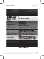
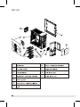
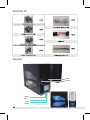
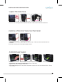
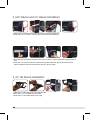
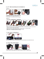
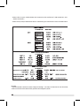
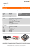
USER MANUAL
AZZA(USA)Technology Ltd.
670 Endeavor Circle
Brea, CA 92821
USA
Phone:714-990-5625
Fax:714-990-5912
www.azzatek.com
SPECIFICATIONS
1
Part List
2
Aircooling System
--- Rear Fan(Exhaust)
120X120X25mm Fan
--- Side Fan(Intake)
120X120X25mm
Blue LED Fan
--- Front Fan(Intake)
80X80X25mm
Blue LED Fan
3
Assembly kit
Diagram
Reset
Power
USB2.0
MIC
Audio
USB2.0
4
INSTALLATION INSTRUCTION
1_Open The Side Panel
1.Remove the locking screws towards the back of the case on the left-hand-side.
2_Remove The Front Panel and Top Panel
1.Hold the front panel by placing one hand on top of the case and one hand at the
bottom.
2.Pull the bottom part front panel towards you.
3_Install Power Supply
1.Place the power supply towards the bottom of the case.
2.Tighten the power supply with screw.
3.This case is designed in a way that the power supply unit can be installed either facing
up or down.
5
4_5.25” Device and 3.5” Device Installation
1.Take off the front panel with the arrows shown on the diagram.
2.Push the 5.25” or the 3.5” mesh cover front from the inside out.
3.Put back the front panel and place the 5.25” or the 3.5” device into the respective drive
slot.
4.Slide the 5.25” device into the respective bay and make sure the screw holes on the
device matches with the marking on the 5.25” device cage.
5_3.5” HD Device Installation
1.Take the 3.5” HD holder out from the HD cage
2.Place your 3.5” HD inside the HD holder.
3.Push the 3.5” HD holder back to HD cage
6
6_2.5” SSD & HD Device Installation
Option 1:
1.Put the 2.5” device on the 3.5” HD holder.
2.Secured the 2.5” device with screw.
3.Push the 3.5” HD holder back to HD cage.
Option 2:
This holder can put two 2.5’’ SDD devices.
*
1.Take off the 2.5” device holder from 3.5” device.
2.Your 2.5” device can be screwed into this holder. All together you may have two 2.5”
devices lock onto the same holder.
3.Secured the 2.5” device with screws, then put this 2.5” device holder
back to 3.5” HD holder and secured it with screws.
4.Push the 3.5” HD holder back to HD cage.
7_Top Fans Installation
Place the fans beneath the top panel and screw the fans from outside the case.
8_Close The Side Panel
Closed the side panel along with those screws that we’ve remove from.
7
Please refer to your motherboard user manual on the sections of "USB connector" and
˙ "Audio Connector."
Please verify the pin definition before connecting the connectors to the motherboard.
˙
Remark:
1.USB and Audio connectors have foolproof design,can only be inserted in one direction.
2.LED connectors have electrically positive and negative poles.
8