1
Alliance System
Advanced Programming
Manual
Copyright
© 2012 UTC Fire & Security Americas Corporation, Inc.
Interlogix is part of UTC Climate Controls & Security,
a unit of United Technologies Corporation. All rights reserved.
This document may not be copied or otherwise reproduced, in whole or in part, except as specifically
permitted under US and international copyright law, without the prior written consent from UTC Fire & Security.
Document number/revision: 1040730 REV G (October 2012).
Disclaimer
THE INFORMATION IN THIS DOCUMENT IS SUBJECT TO CHANGE WITHOUT NOTICE. UTC FIRE &
SECURITY ASSUMES NO RESPONSIBILITY FOR INACCURACIES OR OMISSIONS AND SPECIFICALLY
DISCLAIMS ANY LIABILITIES, LOSSES, OR RISKS, PERSONAL OR OTHERWISE, INCURRED AS A
CONSEQUENCE, DIRECTLY OR INDIRECTLY, OF THE USE OR APPLICATION OF ANY OF THE
CONTENTS OF THIS DOCUMENT. FOR THE LATEST DOCUMENTATION, CONTACT YOUR LOCAL
SUPPLIER OR VISIT US ONLINE AT WWW.UTCFIREANDSECURITY.COM.
This publication may contain examples of screen captures and reports used in daily operations. Examples may include fictitious names of individuals and companies. Any similarity to names and addresses
of actual businesses or persons is entirely coincidental.
Trademarks and patents Alliance product and logo are trademarks of UTC Fire & Security.
Other trade names used in this document may be trademarks or registered trademarks of the manufacturers or vendors of the respective products.
Software license agreement
IMPORTANT: THIS END-USER LICENSE AGREEMENT (“AGREEMENT”) IS A LEGAL AGREEMENT
BETWEEN UTC FIRE & SECURITY AND YOU. READ THE FOLLOWING TERMS AND CONDITIONS
CAREFULLY BEFORE INSTALLING OR USING THIS SOFTWARE. THIS AGREEMENT PROVIDES A
LICENSE FROM UTC FIRE & SECURITY TO USE THE SOFTWARE. IT ALSO CONTAINS WARRANTY
INFORMATION, DISCLAIMERS, AND LIABILITY LIMITATIONS. INSTALLING AND/OR USING THE
SOFTWARE CONFIRMS YOUR AGREEMENT TO BE BOUND BY THESE TERMS AND CONDITIONS.
IF YOU DO NOT AGREE WITH THESE TERMS AND CONDITIONS, DO NOT INSTALL OR USE THE
SOFTWARE OR, IF ALREADY INSTALLED, IMMEDIATELY CEASE ALL USE OF THE SOFTWARE AND
PROMPTLY UNINSTALL ALL COMPONENTS OF THE SOFTWARE.
1. License. In this Agreement, you, the purchaser of the rights granted by this Agreement, are
referred to as You or Your, whether an individual or a business entity of any kind. Subject to the
terms and conditions of this Agreement, UTC Fire & Security,
grants You a nonexclusive license to use the accompanying software (including any upgrades,
modified versions, updates, additions and copies of the software furnished to You during the term of
the Agreement) (“Software”), and all associated media, printed materials, and electronic documentation accompanying the Software (“Documentation”), but only in the country where acquired from
your supplier and/or authorized reseller (“Supplier”). In this Agreement, the Software and Documentation are referred to as the Licensed Product.
All rights to and in the Licensed Product, including, but not limited to, copyrights, patents, trademarks, and trade secrets, belong to UTC FIRE & SECURITY, and UTC FIRE & SECURITY retains title
to each copy of the Software. You may only install and use the Software on a single computer, workstation,
or terminal (“Computing Device”) at one time, unless You have purchased additional copies of the Software,
in which case You may install the software on the number of Computing Devices for which You have
purchased copies of the Software. You may not use the Software over a computer network. You
may not transfer or distribute the Licensed Product to others, in electronic format or otherwise, and
this Agreement shall automatically terminate in the event of such a transfer or distribution. You may
not sell, rent, lease, or sublicense the Software. You may not copy or modify the Licensed Product
for any purpose, including for backup purposes. You may use the original copy of the Software
provided to You for backup purposes. You agree that UTC FIRE & SECURITY at any time, upon
reasonable notice, may audit Your use of the Software for compliance with the terms and conditions of this
Agreement.
2. Term. This Agreement is effective until terminated. You may terminate this Agreement by uninstalling all components of the Software from all Computing Devices and returning the Licensed
Product to UTC FIRE & SECURITY. UTC FIRE & SECURITY may terminate this Agreement if You breach any
of these terms and conditions. Upon termination of this Agreement for any reason, You agree to uninstall all
components of the Software and return the Licensed Product to UTC FIRE & SECURITY. All provisions of this
Agreement relating to (i) disclaimer of warranties; (ii) limitations on liability, remedies, and damages;
and (iii) UTC FIRE & SECURITY’s proprietary rights, shall survive termination of this Agreement.
3. Object code. The Software is delivered in object code only. You may not alter, merge, modify,
adapt, or translate the Software, nor decompile, disassemble, reverse-engineer, or otherwise reduce
the Software to a human-perceivable form, nor create derivative works or programs based on the
Software.
iii
4. Limited warranty. UTC FIRE& SECURITY warrants that for one (1) year from the date of delivery of the
Licensed Product (Software Warranty Period), the functions contained in the Software will be fit for
their intended purpose as described in the applicable Documentation from UTC FIRE & SECURITY, and will
conform in all material respects to the specifications stated in such Documentation. UTC FIRE & SECURITY
does not warrant that the operation of the Software will be uninterrupted or error-free. UTC FIRE & SECURITY
does warrant that the media on which the Software is furnished will be free from defects in materials
and workmanship under normal use for a period of thirty (30) days from the date of delivery (Media
Warranty Period). Except as specifically provided therein, any other software and any hardware
furnished with or accompanying the Software is not warranted by UTC FIRE & SECURITY. Your exclusive
remedy under this limited warranty for nonconforming Software shall be repair or replacement of
the Software, in the sole discretion of UTC FIRE & SECURITY. To obtain a repair or replacement of nonconforming Software, contact UTC FIRE & SECURITY Customer Service toll free at 888-432-7327 or online at
www.utcfireandsecurity.com during the Software Warranty Period. Your exclusive remedy under this
limited warranty for defective media is replacement of the defective media. To receive replacement
media under this limited warranty, return the defective media to Supplier during the Media Warranty
Period, with proof of payment.
EXCEPT AS EXPRESSLY PROVIDED ABOVE, THE LICENSED PRODUCT IS PROVIDED “AS IS” WITHOUT
WARRANTY OF ANY KIND, EITHER EXPRESSED OR IMPLIED, INCLUDING, BUT NOT LIMITED TO, IMPLIED
WARRANTIES OF MERCHANTABILITY OR FITNESS FOR A PARTICULAR PURPOSE AND, EXCEPT AS
EXPRESSLY PROVIDED ABOVE, YOU ASSUME THE ENTIRE RISK AS TO THE QUALITY AND PERFORMANCE OF THE LICENSED PRODUCT.
5. Limitation of liability. UTC FIRE & SECURITY’S SOLE OBLIGATION OR LIABILITY UNDER THIS
AGREEMENT IS THE REPAIR OR REPLACEMENT OF NONCONFORMING SOFTWARE AND/OR
DEFECTIVE MEDIA ACCORDING TO THE LIMITED WARRANTY ABOVE. IN NO EVENT WILL UTC
FIRE & SECURITY BE LIABLE FOR ANY DAMAGES, WHETHER CONSEQUENTIAL, INCIDENTAL,
OR INDIRECT, NOR FOR ANY LOSS OF DATA, LOSS OF PROFITS, OR LOST SAVINGS, ARISING
OUT OF USE OF OR INABILITY TO USE THE SOFTWARE OR DOCUMENTATION (OR ANY HARDWARE
FURNISHED WITH THE SOFTWARE), EVEN IF UTC FIRE & SECURITY HAS BEEN ADVISED OF THE
POSSIBILITY OF SUCH DAMAGES, NOR FOR ANY CLAIM BY ANY THIRD PARTY.
6. General. Any hardware provided to You by UTC FIRE & SECURITY shall not be exported or reexported in
violation of any export provisions of the United States or any other applicable jurisdiction. Any
attempt to sublicense, assign, or transfer any of the rights, duties, or obligations hereunder shall be
void. This Agreement shall be governed by and interpreted under the laws of the State of New York,
United States of America, without regard to conflicts of law provisions. You hereby consent to the
exclusive jurisdiction of the state and federal courts located in Multnomah County, Oregon, to
resolve any disputes arising under or in connection with this Agreement, with venue in Portland,
Oregon.
Restricted rights legend. The Licensed Product is provided with RESTRICTED RIGHTS. In the event
the United States Government or an agency thereof is granted a license, the following additional
terms apply: Restricted Computer Software, as defined in the Commercial Computer Software–
Restricted Rights clause at Federal Acquisition Regulations 52.227-19, and the restrictions as
provided in subparagraphs (c)(1) and (c)(2) thereof; and as applicable, the Government’s rights to use,
modify, reproduce, release, perform, display, or disclose the Software also are restricted as provided
by paragraphs (b)(2) and (b)(3) of the Rights in Noncommercial Technical Data and Computer Software–Small Business Innovative Research (SBIR) Program clause at DFARS 252.227-7018.
YOU ACKNOWLEDGE THAT YOU HAVE READ AND UNDERSTAND THIS AGREEMENT AND AGREE TO BE
BOUND BY ITS TERMS. YOU FURTHER AGREE THAT THIS AGREEMENT IS THE COMPLETE AND EXCLUSIVE STATEMENT OF THE AGREEMENT BETWEEN YOU AND UTC FIRE & SECURITY, AND SUPERSEDES
ANY PROPOSAL OR PRIOR AGREEMENT, ORAL OR WRITTEN, AND ANY OTHER COMMUNICATION
RELATING TO THE SUBJECT MATTER OF THIS AGREEMENT.
Intended use
Use this product only for the purpose it was designed for; refer to the data sheet and user
documentation. For the latest product information, contact your local supplier or visit us online at :
www.utcfireandsecurity.com .
:
iv
Alliance System
Advanced Programming Manual
v
Contents
Preface . . . . . . . . . . . . . . . . . . . . . . . . . . . . . . . . . . . . . . . . . . . . . . . . . . . . . . . . . . . . . . . ix
Conventions used in this document . . . . . . . . . . . . . . . . . . . . . . . . . . . . . . . . . . . . . . .x
Safety terms and symbols. . . . . . . . . . . . . . . . . . . . . . . . . . . . . . . . . . . . . . . . . . . . . . x
Chapter 1.
Introduction . . . . . . . . . . . . . . . . . . . . . . . . . . . . . . . . . . . . . . . . . 1
Product overview . . . . . . . . . . . . . . . . . . . . . . . . . . . . . . . . . . . . . . . . . . . . . . . . . . . . . . . .2
Planning the system . . . . . . . . . . . . . . . . . . . . . . . . . . . . . . . . . . . . . . . . . . . . . . . . . . . . 3
Chapter 2.
Programming basics . . . . . . . . . . . . . . . . . . . . . . . . . . . . . . . . . 5
Programming basics . . . . . . . . . . . . . . . . . . . . . . . . . . . . . . . . . . . . . . . . . . . . . . . . . . . . 6
Clearing the memory . . . . . . . . . . . . . . . . . . . . . . . . . . . . . . . . . . . . . . . . . . . . . . . . . 6
Disarming the system . . . . . . . . . . . . . . . . . . . . . . . . . . . . . . . . . . . . . . . . . . . . . . . . . 7
Accessing the menu. . . . . . . . . . . . . . . . . . . . . . . . . . . . . . . . . . . . . . . . . . . . . . . . . . 7
Programming tools . . . . . . . . . . . . . . . . . . . . . . . . . . . . . . . . . . . . . . . . . . . . . . . . . . . 9
Reset to default . . . . . . . . . . . . . . . . . . . . . . . . . . . . . . . . . . . . . . . . . . . . . . . . . . . . . 10
Programming sequence. . . . . . . . . . . . . . . . . . . . . . . . . . . . . . . . . . . . . . . . . . . . . . .10
vi
Alliance System
Advanced Programming Manual
Chapter 3.
Programming details...... . . . . . . . . . . . . . . . . . . . . . . . . . . . . . . . 13
Required programming . . . . . . . . . . . . . . . . . . . . . . . . . . . . . . . . . . . . . . . . . . . . . . . . . . . 14
Installer menu option 10, Program Text. . . . . . . . . . . . . . . . . . . . . . . . . . . . . . . . . . . . . 15
Installer menu option 13, Time Zones. . . . . . . . . . . . . . . . . . . . . . . . . . . . . . . . . . . . . . 29
Installer menu option 2, Area Database . . . . . . . . . . . . . . . . . . . . . . . . . . . . . . . . . . . . 32
Installer menu option 5, Alarm Groups. . . . . . . . . . . . . . . . . . . . . . . . . . . . . . . . . . . . . . 44
Installer menu option 3, RAS Database . . . . . . . . . . . . . . . . . . . . . . . . . . . . . . . . . . . . 61
Installer menu option 4, DGP Database . . . . . . . . . . . . . . . . . . . . . . . . . . . . . . . . . . . . . 70
Installer menu option 1, Zone Database . . . . . . . . . . . . . . . . . . . . . . . . . . . . . . . . . . . . 72
Installer menu option 9, Communication Options . . . . . . . . . . . . . . . . . . . . . . . . . . . . . 97
System menu option 14, Program Users. . . . . . . . . . . . . . . . . . . . . . . . . . . . . . . . . . . 108
Installer menu option 16, Event to Output . . . . . . . . . . . . . . . . . . . . . . . . . . . . . . . . . . 110
Custom programming . . . . . . . . . . . . . . . . . . . . . . . . . . . . . . . . . . . . . . . . . . . . . . . . . . . 131
Installer menu option 6, Timers . . . . . . . . . . . . . . . . . . . . . . . . . . . . . . . . . . . . . . . . . . 141
Installer menu option 7, System Options. . . . . . . . . . . . . . . . . . . . . . . . . . . . . . . . . . . 121
Installer menu option 8, Auto Reset . . . . . . . . . . . . . . . . . . . . . . . . . . . . . . . . . . . . . . 142
Installer menu option 11, Version Number . . . . . . . . . . . . . . . . . . . . . . . . . . . . . . . . . . 143
Installer menu option 12, Lamp Test. . . . . . . . . . . . . . . . . . . . . . . . . . . . . . . . . . . . . . .144
Installer menu option 14, Defaults. . . . . . . . . . . . . . . . . . . . . . . . . . . . . . . . . . . . . . . . .145
Software IUM . . . . . . . . . . . . . . . . . . . . . . . . . . . . . . . . . . . . . . . . . . . . . . . . . . . . . . . .146
Installer menu option 15, Alarm Group Restrictions . . . . . . . . . . . . . . . . . . . . . . . . . . .147
Installer menu option 17, Auto Arm/Disarm . . . . . . . . . . . . . . . . . . . . . . . . . . . . . . . . . .155
Installer menu option 18, Vaults. . . . . . . . . . . . . . . . . . . . . . . . . . . . . . . . . . . . . . . . . . 1. 58
Installer menu option 19, Area Linking. . . . . . . . . . . . . . . . . . . . . . . . . . . . . . . . . . . . . 160
.
Installer menu option 20, System Codes . . . . . . . . . . . . . . . . . . . . . . . . . . . . . . . . . . . .161
Installer menu option 21, Zone Shunts. . . . . . . . . . . . . . . . . . . . . . . . . . . . . . . . . . . . . 163
Installer menu option 22, Time Zone to Follow Output . . . . . . . . . . . . . . . . . . . . . . . . .169
Installer menu option 23, Poll Errors . . . . . . . . . . . . . . . . . . . . . . . . . . . . . . . . . . . . . . .170
Installer menu option 24, Download to Remote Devices . . . . . . . . . . . . . . . . . . . . . . . 172
.
Installer menu option 25, Display Last Card. . . . . . . . . . . . . . . . . . . . . . . . . . . . . . . . . 174
Installer menu option 28, To Remote Device . . . . . . . . . . . . . . . . . . . . . . . . . . . . . . . .175
Installer menu option 29, Computer Connection . . . . . . . . . . . . . . . . . . . . . . . . . . . . . 177
Installer menu option 30, Printer . . . . . . . . . . . . . . . . . . . . . . . . . . . . . . . . . . . . . . . . . .184
Installer menu option 31, Battery Testing . . . . . . . . . . . . . . . . . . . . . . . . . . . . . . . . . . . 187
Installer menu option 32, Custom LCD Message. . . . . . . . . . . . . . . . . . . . . . . . . . . . . 190
vii
Installer menu option 33, Program Next Service . . . . . . . . . . . . . . . . . . . . . . . . . . . . 191
Installer menu option 34, Program System Event Flags . . . . . . . . . . . . . . . . . . . . . . 192
Installer menu option 35, Program Macro Logic . . . . . . . . . . . . . . . . . . . . . . . . . . . . 200
Installer menu option 42, Reporting Class Database . . . . . . . . . . . . . . . . . . . . . . . . 204
Installer menu option 43, Test Calls . . . . . . . . . . . . . . . . . . . . . . . . . . . . . . . . . . . . . 207
Installer menu option 50, Channel Mapping . . . . . . . . . . . . . . . . . . . . . . . . . . . . . . . 208
Installer menu option 51, Engineering Reset . . . . . . . . . . . . . . . . . . . . . . . . . . . . . . . 208
Installer menu option 52, Voice Reporting . . . . . . . . . . . . . . . . . . . . . . . . . . . . . . . . . 208
Installer menu option 53, Program DVMRe . . . . . . . . . . . . . . . . . . . . . . . . . . . . . . . . 209
Installer menu option 54, Engineer Walk Test . . . . . . . . . . . . . . . . . . . . . . . . . . . . . . 213
Chapter 4.
Reference . . . . . . . . . . . . . . . . . . . . . . . . . . . . . . . . . . . . . . . . . 217
Event flags. . . . . . . . . . . . . . . . . . . . . . . . . . . . . . . . . . . . . . . . . . . . . . . . . . . . . . . . . . . . 218
Reporting . . . . . . . . . . . . . . . . . . . . . . . . . . . . . . . . . . . . . . . . . . . . . . . . . . . . . . . . . . . . . 222
Zone event reporting . . . . . . . . . . . . . . . . . . . . . . . . . . . . . . . . . . . . . . . . . . . . . . . . . 222
DVMRe interface . . . . . . . . . . . . . . . . . . . . . . . . . . . . . . . . . . . . . . . . . . . . . . . . . . . . . . . 230
Introduction . . . . . . . . . . . . . . . . . . . . . . . . . . . . . . . . . . . . . . . . . . . . . . . . . . . . . . . . 230
Installing the DVMRe interface . . . . . . . . . . . . . . . . . . . . . . . . . . . . . . . . . . . . . . . . . . 231
Time and date synchronization . . . . . . . . . . . . . . . . . . . . . . . . . . . . . . . . . . . . . . . . . .232
Event text insertion . . . . . . . . . . . . . . . . . . . . . . . . . . . . . . . . . . . . . . . . . . . . . . . . . . 233
Using panel relays to control DVMRe macros. . . . . . . . . . . . . . . . . . . . . . . . . . . . . . 235
Using DVMRe alarm inputs to activate panel zones . . . . . . . . . . . . . . . . . . . . . . . . . 236
Search and play . . . . . . . . . . . . . . . . . . . . . . . . . . . . . . . . . . . . . . . . . . . . . . . . . . . . 238
Glossary. . . . . . . . . . . . . . . . . . . . . . . . . . . . . . . . . . . . . . . . . . . . . . . . . . . . . . . . . . . . . . 242
Installer programming map . . . . . . . . . . . . . . . . . . . . . . . . . . . . . . . . . . . . . . . . . . . . . . 246
Chapter 5.
Support . . . . . . . . . . . . . . . . . . . . . . . . . . . . . . . . . . . . . . . . . . . .259
Contacting technical support. . . . . . . . . . . . . . . . . . . . . . . . . . . . . . . . . . . . . . . . . . . . . . 260
Online publication library. . . . . . . . . . . . . . . . . . . . . . . . . . . . . . . . . . . . . . . . . . . . . . .260
viii
Alliance System
Advanced Programming Manual
ix
Preface
This is the UTC Fire & Security Alliance System Programming Manual for Alliance security panel
models AL-4017 and AL-4617. This document includes an overview of how to plan an
Alliance system, and detailed instructions explaining:
•
•
•
•
basic Alliance system programming concepts,
each of the programming options,
how to use event flags,
Alliance panel reporting codes.
There is also information describing how to contact technical support if you have questions
or concerns.
To use this document effectively, you should be a trained Alliance system installation
technician, or have similar qualifications, including the following minimum qualifications:
•
•
a basic knowledge of security management software; and
a basic knowledge of security systems and components.
Read these instructions and all ancillary documentation entirely before installing or
operating this product. The most current versions of this and related documentation may be
found on our website. Refer to Online publication library on page 260 for instructions on
accessing our online publication library.
Note:
A qualified service person, complying with all applicable codes, should perform whatever
hardware installation is required.
x
Alliance System
Advanced Programming Manual
Conventions used in this document
The following conventions are used in this document:
Bold
Menu items and buttons.
Italic
Emphasis of an instruction or point; special terms.
File names, path names, windows, panes, tabs, fields, variables, and other GUI
elements.
Titles of books and various documents.
Blue italic
(Electronic version.) Hyperlinks to cross-references, related topics, and URL
addresses.
Monospace
Text that displays on the computer screen.
Programming or coding sequences.
Safety terms and symbols
These terms may appear in this manual:
CAUTION:
Cautions identify conditions or practices that may result in damage to the equipment
or other property.
WARNING:
Warnings identify conditions or practices that could result in equipment damage or
serious personal injury.
Chapter 1 Introduction
This chapter provides an overview of the Alliance system and
instructions for planning the best approach to programming the
system.
In this chapter:
Product overview . . . . . . . . . . . . . . . . . . . . . . . . . . . . 2
Planning the system . . . . . . . . . . . . . . . . . . . . . . . . . . 3
2
Alliance System
Advanced Programming Manual
Product overview
The Alliance system is a single, integrated platform combining flexible hardware,
powerful software, and multiple technologies.
The system features:
•
•
•
•
•
•
•
•
•
Integrated alarm and access control for up to 256 inputs and 64 doors
Modular RS-485 data bus with continuous polling of up to 16 remote arming
stations (RASes) and 15 data control panels (DGPs)
Programmable Logic Control (PLC) with 24 Macro logic equations
255 programmable outputs
Built-in PSTN dialer
2-state or 4-state monitored analog inputs
Programming, monitoring, and service both on-site and by remote computer
Switched mode power supply
Steel enclosures
Chapter 1
Introduction > Planning the system
Planning the system
You should create a system plan prior to installing and programming an Alliance system.
A system plan should include:
Site map. Create a basic drawing that shows the premises with the location of all
required system equipment (labeled with name and zone number or address). If the
anti-passback function is required for the system, Regions and IN/OUT reader
addresses should be defined on the site map.
Equipment list. Use the site map to create a list of all equipment needed for the
system.
Maximum standby current. Use the equipment list and the Battery Calculation
Worksheet in the AL-4017/AL-4617 Installation and Quick Programming Manual
(1040731) to add up all of the input current required by every piece of equipment
and determine the proper battery amp hour rating to meet your minimum standby
time requirements.
Text word list. Use the site map to create a list of text words needed to identify all
equipment and zone names for the system.
Programming worksheets. Use worksheets to record programming details. Blank
worksheets are provided in Alliance System User’s Guide (1040729).
3
4
Alliance System
Advanced Programming Manual
Chapter 2 Programming basics
This chapter provides instructions for getting started with
programming the Alliance system.
In this chapter:
Programming basics . . . . . . . . . . . . . . . . . . . . . . . . . . 6
Clearing the memory . . . . . . . . . . . . . . . . . . . . . . . . . 6
Programming tools . . . . . . . . . . . . . . . . . . . . . . . . . . . 9
Reset to default . . . . . . . . . . . . . . . . . . . . . . . . . . . . . 10
Programming sequence . . . . . . . . . . . . . . . . . . . . . . 10
6
Alliance System
Advanced Programming Manual
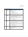
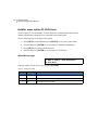
Programming basics
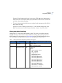
There are 24 top-level menus in the Alliance system (see Table 1). Most of the programming
described in this manual is accessed via option 19, Installer Programming (see Table 2).
Table 1.
Alliance system menu (top level)
1. Panel Status
13. Start Auto Disarm Test
2. Active Zones
14. Program Users
3. Zones in Alarm
15. Time and Date
4. Bypassed Zones
16. Bypass/Unbypass RAS/DGP
5. History
17. Enable/Disable Service Technician
6. Test Report
18. Reset Cameras
7. Service Menu
19. Installer Programming
8. Film Counters
20. Door and Floor Groups
9. List Zone Names
21. Holidays
10. Bypass Zone
22. Open Doors
11. Unbypass Zone
23. Unlock, Lock, Disable and Enable Doors
12. Test Zone
24. Print History
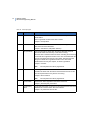
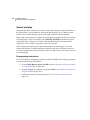
Clearing the memory
After the Alliance system is installed, you need to clear the panel memory and apply power
before you can start programming.
Use the following steps to clear the panel memory:
1. Remove all power to the control panel (AC and battery).
2. Short the “KILL” jumper for about 30 seconds.
3. Open the “KILL” jumper.
4. Apply power to the control panel.
The panel memory is now cleared and restored to factory defaults.
Chapter 2
Programming basics
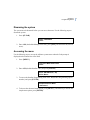
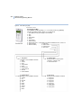
Disarming the system
The system must be disarmed before you can access the menu. Use the following steps to
disarm the system.
1. Press [CLEAR].
05:43 02APR2006
Code:
2. Enter 1122 (the default Manager PIN code), press [OFF], and then enter 0 (select all
areas).
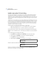
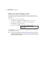
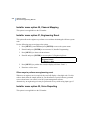
Accessing the menu
Use the following steps to access the Alliance system menu when the Code prompt is
displayed on the bottom line of the RAS.
1. Press [MENU*].
To Access Menu Enter Code
Code:
2. Enter 1278 (default Installer code), and press [ENTER].
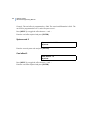
0-Exit ENTER-Down, *Up
0-Exit, Menu:
3. To access the Installer Programming menu enter 19 (Installer Programming option
number), and press [ENTER].
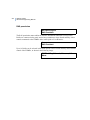
Simple/Advanced Menu
*-Advanced
4. To choose the advanced menu option, press [MENU*]. Alternatively, to choose the
simple menu option, press [ENTER].
7
8
Alliance System
Advanced Programming Manual
Note:
The simple menu option will limit access to a number of options in the Installer Programming
menu. It is recommended that you always choose the advanced menu option.
Installer Programming
0-Exit, Menu:
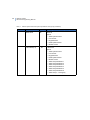
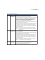
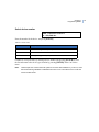
You can now select the programming option you need from the Installer Programming menu
(see Table 2).
Table 2.
Installer Programming menu options
1. Zone Database
28. To Remote Devices
2. Area Database
29. Computer Connection
3. RAS Database
30. Printer
4. DGP Database
31. Battery Testing
5. Alarm Groups
32. Custom LCD Message
6. Timers
33. Program Next Service
7. System Options
34. Program System Event Flags
8. Auto Reset
35. Program Macro Logic
9. Communication Options
36. Reserved Menu
10. Program Text
37. Reserved Menu
11. Version Number
38. Reserved Menu
12. Lamp Test
39. Reserved Menu
13. Time Zones
40. Reserved Menu
14. Defaults
41. Reserved Menu
15. Alarm Group Restrictions
42. Reporting Class Database
16. Event to Output
43. Test Calls
17. Auto Arm/Disarm
44. Reserved Menu
18. Vaults
45. Reserved Menu
19. Area Linking
46. Reserved Menu
20. System Codes
47. Reserved Menu
21. Zone Shunts
48. Reserved Menu
22. Time Zone to Follow Output
49. Reserved Menu
23. Poll Errors
50. Channel Mapping
24. Download to Remote Device
51. Engineering Reset
Chapter 2
Programming basics
25. Display Last Card
52. Voice Reporting
26. Reserved Menu
53. Program DVMRe
27. Reserved Menu
54. Engineer Walk Test
Programming tools
Navigation tools
The following keys are used to move between system menus or between menu options in
Installer Programming:
•
•
•
•
Press [ENTER] to scroll forward one menu option.
Press [MENU*] to scroll backward one menu option.
Enter the menu number and press [ENTER] to jump directly to a menu.
Enter 0 and press [ENTER] or press [CLEAR] to exit the menu.
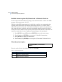
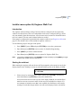
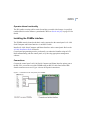
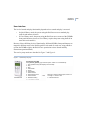
The LCD display
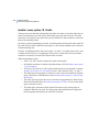
The LCD display on the keypad has two lines of characters. Each line contains a different
type of information.
Figure 1. Sample LCD display
YES – Internal Siren, Program in DB
* - Change, 0 - Skip
For example, the top line in Figure 1 contains system information, and the bottom line
contains the instructions and characters you can enter on the keypad. For this example, you
could enter 0 to skip this option.
9
10
Alliance System
Advanced Programming Manual
Programming the options
In this document “enter” is used in the following ways:
•
•
Press the key (or sequence of keys) on the RAS keypad that corresponds with the
required value. For example, press the 0 key to ‘enter’ the value 0.
Press the [ENTER] key on the RAS keypad to accept the value that you entered (or
to accept the value displayed on the LCD display).
To program a value, such as a number or amount, enter the value and press [ENTER]. The
information will be saved and the display will show the next option.
To program a YES/NO option, press [ENTER] to accept the display or press [MENU*] to
toggle between YES and NO. Enter 0 to skip options.
Note:
If a value is already programmed and needs to be changed, enter the new value and press
[ENTER] to change the value.
Reset to default
Sometimes it is necessary to bring the control panel back to factory defaults (i.e. when
programming a system that has been without power for more than two weeks). Refer to
Installer menu option 14, Defaults on page 145 for instructions.
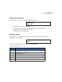
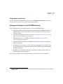
Programming sequence
The sequence of the programming steps is very important. Perform the first ten steps in the
sequence shown to ensure correct programming of the system.
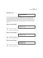
Required programming (must be done in sequence shown)
1. Installer Programming menu option 10, Program Text
2. Installer Programming menu option 13, Time Zones
3. Installer Programming menu option 2, Area Database
4. Installer Programming menu option 5, Alarm Groups
5. Installer Programming menu option 3, RAS Database
6. Installer Programming menu option 4, DGP Database
7. Installer Programming menu option 1, Zone Database
Chapter 2
Programming basics
8. Installer Programming menu option 9, Communication Options
9. System menu option 14, Program Users
10. Installer Programming menu option 16, Event to Output
These options are described in detail in Required programming on page 14.
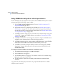
Custom programming (can be done in any order)
Installer Programming menu option 6, Timers
Installer Programming menu option 7, System Options
Installer Programming menu option 8, Auto Reset
Installer Programming menu option 11, Version Number
Installer Programming menu option 12, Lamp Test
Installer Programming menu option 14, Defaults
Installer Programming menu option 15, Alarm Group Restrictions
Installer Programming menu option 17, Auto Arm/Disarm
Installer Programming menu option 18, Vaults
Installer Programming menu option 19, Area Linking
Installer Programming menu option 20, System Codes
Installer Programming menu option 21, Zone Shunts
Installer Programming menu option 22, Time Zone to Follow Output
Installer Programming menu option 23, Poll Errors
Installer Programming menu option 24, Download to Remote Devices
Installer Programming menu option 25, Display Last Card
Installer Programming menu option 28, To Remote Device
Installer Programming menu option 29, Computer Connection
Installer Programming menu option 30, Printer
Installer Programming menu option 31, Battery Testing
Installer Programming menu option 32, Custom LCD Message
Installer Programming menu option 33, Program Next Service
Installer Programming menu option 34, Program System Event Flags
Installer Programming menu option 35, Program Macro Testing
Installer Programming menu option 42, Reporting Class Database
11
12
Alliance System
Advanced Programming Manual
Installer Programming menu option 43, Test Calls
Installer Programming menu option 51, Engineering Reset
Installer Programming menu option 52, Voice Reporting
Installer Programming menu option 53, Program DVMRe
Installer Programming menu option 54, Engineer Walk Test
These options are described in detail in Custom programming on page 113.
Chapter 3 Programming details
This chapter provides detailed instructions about programming
the Alliance system, listed in the recommended order of
programming.
In this chapter:
Required programming . . . . . . . . . . . . . . . . . . . . . . . 14
Custom programming . . . . . . . . . . . . . . . . . . . . . . . 113
14
Alliance System
Advanced Programming Manual
Required programming
The sequence of the programming steps is very important to ensure correct programming of
the system. Perform the steps in the sequence of the following sections:
Installer menu option 10, Program Text . . . . . . . . . . . . . . . . . . . . . 15
Installer menu option 13, Time Zones . . . . . . . . . . . . . . . . . . . . . . . 29
Installer menu option 2, Area Database . . . . . . . . . . . . . . . . . . . . . 32
Installer menu option 5, Alarm Groups . . . . . . . . . . . . . . . . . . . . . . 44
Installer menu option 3, RAS Database. . . . . . . . . . . . . . . . . . . . . . 61
Installer menu option 4, DGP Database . . . . . . . . . . . . . . . . . . . . . 70
Installer menu option 1, Zone Database . . . . . . . . . . . . . . . . . . . . . 72
Installer menu option 9, Communication Options. . . . . . . . . . . . . . 97
System menu option 14, Program Users . . . . . . . . . . . . . . . . . . . . 108
Installer menu option 16, Event to Output . . . . . . . . . . . . . . . . . . 110
See also Custom programming on page 113 for more options.
Chapter 3
Programming details
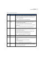
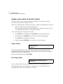
Installer menu option 10, Program Text
The control panel uses a library of text words to program names or text into the system (e.g.
zone names, area names, etc.). These text words form part of the variable text that appears
on the LCD display.
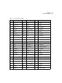
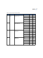
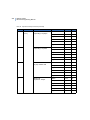
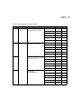
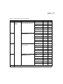
All the text words in the library are identified with a reference number (from 001 to 899).
See Table 4, Text word library on page 17 for the list of text words available.
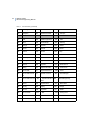
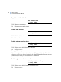
Program new text words
If your system requires text words not found in the library, you can program up to 100
additional words for your application needs. Record these additional text words in Table 5,
Programmed text words on page 27. Text words can be any combination of 16 characters,
including letters, numbers, spaces (making two words for one reference number), or
punctuation.
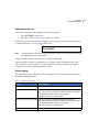
Use the following steps to navigate to the option:
1. Press [MENU*] enter 1278 and press [ENTER] to access the system menu.
2. Enter 19 and press [ENTER] to access menu 19, Installer Programming.
3. Press [MENU*] to choose advanced menu.
4. Enter 10 and press [ENTER] to access option 10, Program Text.
5. Enter the word reference number from 900 to 999.
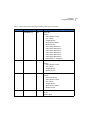
6. Using the number keys on the keypad, enter the required letter (see Table 3, Key
press to get character on page 16. Press [ENTER] to advance to the next letter.
Press [MENU*] to advance to the next word. Press [CLEAR] to exit the menu.
15
16
Alliance System
Advanced Programming Manual
Table 3.
Key
Key press to get character
Key press to get character
1st
2nd
3rd
4th
5th
6th
7th
1
A
B
C
1
a
b
c
2
D
E
F
2
d
e
f
3
G
H
I
3
g
h
i
4
J
K
L
4
j
k
l
5
M
N
O
5
m
n
o
6
P
Q
R
6
p
q
r
7
S
T
U
7
s
t
u
8
V
W
X
8
v
w
x
9
Y
Z
sp
9
y
z
sp
0
.
,
?
!
:
;
-
Key
8th
9th
10th
11th
12th
13th
14th
0
+
#
*
(
)
Key
15th
16th
17th
18th
19th
0
_
@
&
Key
22nd
23rd
0
<
>
$
‘
“
20th
21st
%
/
Chapter 3
Programming details
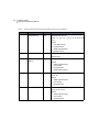
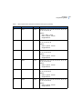
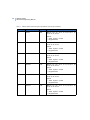
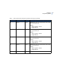
Table 4.
Text word library
A
001
Above
008
Area
009
002
Access
332
Area One
421
Art
003
Accountant
333
Area Two
265
Assistant
264
Accounts
334
Area Three
367
Assistant Manager
417
Accounts Manager
335
Area Four
369
Assistant Manager Day
004
Across
336
Area Five
422
Assistant Principal
404
Admin
337
Area Six
423
Assoc Administrator
418
Administration
338
Area Seven
010
At
272
Air Conditioning
339
Area Eight
011
ATM
005
Alarm
340
Area Nine
308
Atrium
006
All
341
Area Ten
012
Audio
362
All Area User Code
342
Area Eleven
520
All ATMs
343
Area Twelve
419
Amenities
344
Area Thirteen
351
Auto Disarm
295
Analog
345
Area Fourteen
014
Automatic
420
Ancillary Staff
346
Area Fifteen
381
Auto Reset
514
And
347
Area Sixteen
015
Aux
007
APC
410
Armoured Car
424
AV Production
016
Back
020
Bay
028
Bottom
349
Baker
021
Beam
326
Box
376
Baker 1
022
Bedroom
539
BRD
013
350
Arming
Auto
Auto Arm
B
17
18
Alliance System
Advanced Programming Manual
Table 4.
Text word library (continued)
377
Baker 2
023
Bell
267
BRG
017
Bar
024
Board
029
Building
018
Basement
025
Boardroom
425
Bulk Store
019
Bathroom
026
Body
030
Business
273
Battery
027
Boiler
031
Button
032
Cabinet
045
Charge
055
Compactor
033
Cage
046
Chief
056
Computer
034
Call
047
Cigarettes
429
Computer Room
293
Calibration
048
City
057
Conference
035
Camera
427
Class Room
430
Conference Room
036
Canteen
352
Cleaner
058
Contact
037
Car
411
Cleaner Selling
059
Control
038
Caroline
412
Cleaner Front
299
Corridor
039
Cash
413
Cleaner Admin
358
Count
408
Cash Office
049
Clerk
060
Counter
040
CCTV
050
Clip
325
Cover
041
Ceiling
051
Cold
432
Covered Area
042
Cellar
052
Combination
061
Covering
043
Central
428
Commerce
522
Curtain
426
Central Bulk Store
431
Center
C
053
054
Commercial
Communication
269
062
Custody
Customer
Chapter 3
Programming details
Table 4.
Text word library (continued)
D
274
Dairy
066
Dining
503
Double
433
Dark Room
296
Digital
275
DOTL
304
Data
067
Dispatch
070
Downstairs
063
Delayed
435
District Facility
071
Driveway
266
Desk
068
Dock
072
Drug
064
Detector
069
Door
436
Dry Craft
434
Developmental
465
Doors
074
DUALTEK
065
DGP
543
Door Keypad
073
Duct
330
Dump
075
Duress
437
Early
079
Emergency
083
Equipment
076
East
297
Engineering
441
Equipment Store
438
Education
080
End
298
Evaluation
077
Electric
081
Enquiry
084
Exit
078
Electrical
082
Entry
085
Exterior
439
Electronics
440
Entry/Display Area
087
Factory
092
Film
278
Forced Door
442
Factory Manager
093
Fire
096
Foyer
276
Fail
443
Fitness Testing
097
Freezer
088
Failure
094
Floor
098
Front
089
Fashion
323
FLR
379
Front Counter
E
086
External
F
19
20
Alliance System
Advanced Programming Manual
Table 4.
Text word library (continued)
090
Fence
095
Foil
538
Front Door Keypad Bank 1
091
File
277
Food
542
Front Door Keypad Bank 2
099
Games
448
Graphics
395
Group 21
283
Gaming
312
Grd/Flr
396
Group 22
100
Gas
449
Groundsman Store
397
Group 23
101
Garden
106
Ground
398
Group 24
102
Garage
303
Group
399
Group 25
103
Gate
385
Group 11
400
Group 26
104
General
386
Group 12
401
Group 27
445
General Circulation
387
Group 13
402
Group 28
530
General Staff
388
Group 14
403
Group 29
519
General Staff 1
389
Group 15
450
Guard
532
General Staff 2
390
Group 16
548
Guard Patrol Full
446
GLA
391
Group 17
549
Guard Patrol Limited
447
GLA/Stage
392
Group 18
279
Gun
105
Glass
393
Group 19
315
GYM
328
Goods
394
Group 20
107
Hall
109
Heat
444
Hallway
364
High Level User
Master
108
Hand
527
High SSO
G
H
361
382
451
Holdup Bar
Holdup Button
Home Economics
Chapter 3
Programming details
Table 4.
327
Text word library (continued)
Hatch
110
Holdup
111
In
112
Input
280
Inertia
452
Instrument Store
281
Inner
113
Interior
Janitor
115
384
Kamahira
355
545
I
114
Internal
524
Isolate
Jewelry
365
Junction
302
Keypad
117
Kitchen
Key
353
Keyswitch Inhibited
348
Kiosk
Keybox
116
Kick bar
118
Landing
121
Level
126
Loading
282
Lay By
122
Library
127
Loans
454
Learning
123
Lift
128
Lobby
119
Left
124
Light
129
Lock
120
Lending
125
Liquor
130
Long Range
375
Loss Prevention
131
Lounge
284
Low
J
453
K
L
363
Low Level User
Master
528
Low SSO
132
Lower
133
Lunch
458
Manual
460
Metal Workshop
M
134
Machine
21
22
Alliance System
Advanced Programming Manual
Table 4.
Text word library (continued)
455
Machinery Store
139
Master
143
Microwave
135
Magnetic
044
MASTER ADVISOR
136
Main
140
Mat
456
Main Admin Office
459
Materials Store
457
Main Entry
329
Meat
147
Motor
285
Mains
523
Mechanic
461
Multipurpose Room
318
Makash
141
Medical
462
Music
137
Manager
316
Meeting
463
Music Practice
138
Manchester
142
Mens
464
MYCP & Interview
313
ND
11
Night
154
North East
148
Near
370
Night Manager
155
Note
268
New
354
Noise Makers
Isolated
149
Next
152
North
150
Next To
153
North West
157
Off
160
On
360
Out
158
Office
161
Open
286
Outer
159
Officer
466
Orchestral
162
Over
163
Panel
169
Phone
471
Pre-School
164
Panic
170
PIR
472
Preparation
144
145
146
Middle
Money
Motion
N
156
Number
O
P
Chapter 3
Programming details
Table 4.
Text word library (continued)
165
Park
322
360 PIR
473
Principal
467
Passage
287
Pit
311
Print
166
Passive
288
Plant
474
Printery
468
Patrol
470
Playroom
475
Production
531
Patrol 2
357
Pneumatic
310
Productivity
533
Patrol 3
171
Point
476
Professional Support
167
Penset
172
Pool
175
Protection
469
Performing Art
Center
477
Public Waiting
168
Perimeter
173
Port
176
Pull
321
Personnel
174
Power
177
Pump
356
POPUP
Q
478
Quiet Learning
R
178
Rack
186
Record
482
Resource Store
179
Radio
187
Reed Switch
300
Retrofit
180
Raid
479
Reference
306
RF
181
Ramp
188
Refrigeration
191
Right
317
RAS
307
Register
309
Riser
182
Reader
189
Remote
192
Road
183
Rear
190
Representative
193
Roller Door
184
Receiving
480
407
Receiving Dock
518
Reprographic
Production
Request To Exit
194
195
Roof
Room
23
24
Alliance System
Advanced Programming Manual
Table 4.
Text word library (continued)
378
Receiving Door
294
Research
263
RSB
185
Reception
481
Resource Center
196
Rumpus
197
Safe
489
Small Equip Store
221
Stair
305
Sales
490
Small Group
222
Stairway
270
Savings
212
Smoke
223
Station
483
School
213
Sound
224
Stereo
484
Science
214
South
290
Stop
198
Screen
215
South East
371
Stock Hand
199
Secretary
216
South West
372
Stock Hand 1
324
Security
217
Spare
373
Stock Hand 2
207
Seismic
491
Special
374
Stock Hand 3
200
Selling
414
Special Access 1
406
Stock Room
529
Senior Staff
45
Special Access 2
225
Store
535
Senior Staff Second
TZ
537
Senior Staff Third TZ
201
Sensor
493
Sports Store
485
Servery
494
Spray
226
Storage
202
Service
218
Sprinkler
227
Strobe
546
Service Code
219
SRT
359
Strong room
547
Service Allow
544
SSO
228
Strike
405
Service Bay
314
ST
498
Student Center
S
416
492
Special Access 3
366
Special Education 368
Area
331
Store Manager
Store Manager Day
Store Room
Chapter 3
Programming details
Table 4.
Text word library (continued)
486
Service Manager
220
Staff
487
Services Room
495
Staff & Amenities
203
Shop
525
Staff Areas 1 to 4
501
Studio
204
Short Tom
526
Staff Areas 5 to 8
319
Substation
205
Show
380
Staff Door
206
Side
521
208
Sign
409
Staff Entry
230
Supervisor
488
Single
496
Staff Lounge
231
Surveillance
209
Siren
497
Staff Room
232
Switch
210
Shutter
534
Staff Second TZ
292
Switchboard
211
Sliding
536
Staff Third TZ
233
System
289
Small
Staff Window
Bypass
499
500
291
229
Student Waiting
Studies
Sump
Supermarket
T
234
Tamper
236
Teller
235
Tape
507
Temp GLA
241
Tool
504
Teacher
508
Temp Typing
242
Top
505
Teacher Work
237
Temperature
271
Trading
502
Tea Room
509
Textile Store
510
Trades
301
Technical
044
The Challenger
243
Transmitter
506
Technician
238
Time
244
Trap
320
Telecom
239
To
511
Typing GLA
U
240
Toilet
25
26
Alliance System
Advanced Programming Manual
Table 4.
Text word library (continued)
245
Ultrasonic
513
Unit
512
Under
246
Upper
248
Valve
541
Vault RAS Bank 2
249
Vault
250
Vent
540
Vault RAS Bank 1
247
Upstairs
V
251
Ventilator
252
253
83
Video
Voltage
Volumetric
W
254
Wall
257
Window
255
Warehouse
258
Wired Grid
256
West
259
Women's
515
Wet Craft
516
Wood Workshop
Y
261
Z
Yard
262
Zone
517
260
Work Room
Workshop
Chapter 3
Programming details
Table 5.
Programmed text words
900
901
902
903
904
905
906
907
908
909
910
911
912
913
914
915
916
917
918
919
920
921
922
923
924
925
926
927
928
929
930
931
932
933
934
935
936
937
938
939
940
941
942
943
944
945
946
947
948
949
950
951
952
053
054
955
956
957
958
959
960
961
962
963
964
965
966
967
968
27
28
Alliance System
Advanced Programming Manual
Table 5.
Programmed text words (continued)
969
970
971
972
973
974
975
976
977
978
979
980
981
982
983
984
985
986
987
988
989
990
991
992
993
994
995
996
997
998
999
Chapter 3
Programming details
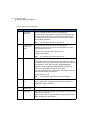
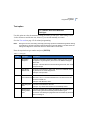
Installer menu option 13, Time Zones
Time zones are used to create time slots in which certain events can take place. Time zones
are assigned to alarm groups, door groups, floor groups, relays/outputs, arm/disarm timers,
and out-of-hours access reporting to restrict or enable specific operations during specific
time periods. There are two main types of time zones, soft and hard.
Soft time zones
Soft time zones are programmed to be valid when an output is active. See Installer menu
option 22, Time Zone to Follow Output on page 169 for programming information on soft
time zones.
Also see Activating soft time zones from a RAS on page 30.
Hard time zones
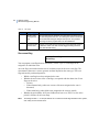
Hard time zones are numbered 1 to 24 and are programmed for specific time periods. Each
hard time zone is made up of one to four sub-time zones containing:
•
•
•
•
A start time
An end time
The weekdays that the sub-time zone is valid
An option to make the sub-time zone valid on holidays
Example: Time Zone 1 could contain the following sub-time zones:
1.1
08:00 to 17:00
Mo, Tu, We, Th, Fr
1.2
08:00 to 15:00
Sa, Su
1.3
18:00 to 20:00
Mo, Tu, We, Th, Fr
1.4
18:00 to 22:00
Sa, Su
Use consecutive sub-time zones when a time zone’s start time and end time are on different
days. The hours 24:00 and 00:00 are not recognized as end times and can therefore be used
to extend a period to the next sub-time zone.
A time zone is invalid on any holiday that has been declared in the holiday date file (system
menu 21) unless “HOL” is included as a day in the sub time zone. If “HOL” is included, the
29
30
Alliance System
Advanced Programming Manual
time zone is valid on any holiday (even if the day of the week that it falls on is not included
in the sub-time zone).
Note:
Time zone 0 (zero) is a 24-hour time zone (always valid) and is not programmable.
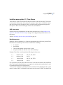
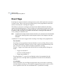
Activating soft time zones from a RAS
AL-111x-series RASes provide function key emulation, which may be used to activate soft
time zones in the range 41 through 63 for approximately four seconds. Longer durations can
be achieved by use of macros: the soft time zone can be used to activate an output, which
can then be used as an input to a macro.
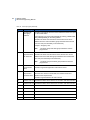
When using an AL-111x-series RAS, press the [Open] key simultaneously with a numbered
key (1 through 6) to activate a soft time zone. The soft time zone applied by the key
combination is based on Table 6.
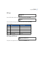
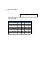
Table 6.
Mapping of RAS function key emulation to time zone numbers by RAS address
Key
RAS 1
RAS 2
RAS 3
RAS 4
RAS 5
RAS 6 to 16
1
TZ 42
TZ 46
TZ 50
TZ 54
TZ 58
not applicable
2
TZ 43
TZ 47
TZ 51
TZ 55
TZ 59
not applicable
3
TZ 44
TZ 48
TZ 52
TZ 56
TZ 60
not applicable
4
TZ 45
TZ 49
TZ 53
TZ 57
TZ 61
not applicable
5
— activates time zone 62 for any RAS address from 1 through 16 —
6
— activates time zone 63 for any RAS address from 1 through 16 —
Chapter 3
Programming details
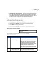
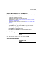
Programming hard time zones
Use the following steps to navigate to the option:
1. Press [MENU*] enter 1278 and press [ENTER] to access the system menu.
2. Enter 19 and press [ENTER] to access menu 19, Installer Programming.
3. Press [MENU*] to choose advanced menu.
4. Enter 13 and press [ENTER] to access option 13, Time Zones.
Time Zones
Time Zone No:
5. Enter the time zone number and press [ENTER]. The display will begin with the
first of four sub-time zones (for example TZ 1.1).
TZ 1.1 Start - 08:00 End - 00:00
Start Hours:
6. Enter the start time hour and press [ENTER].
TZ 1.1 Start-08:00 End-00:00
Start Mins:
7. Enter the start time minutes and press [ENTER].
TZ 1.1 Start-08:00 End-00:00
End Hours:
8. Enter the end time hour and press [ENTER].
TZ 1.1 Start-08:00 End-00:00
End Mins:
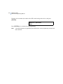
9. Enter the end time minutes and press [ENTER]. The start and end times
programmed will show on the top line of the display.
10. Press [ENTER] to advance to the day of the week field.
TZ 1.1 Days:--,Mo,Tu,We,--,--,--,Hol
(1) Sun - (8) Hol:
31
32
Alliance System
Advanced Programming Manual
11. Enter the start day needed and press [ENTER]. For the days of the week, enter their
numerical value with Sunday as “1” and holiday as “8”. Repeat for each day needed.
The active time zone days will show on the top line of the display.
12. The next displays contain sub-time zones 1.2 through 1.4 that can be programmed in
the same way as sub-time zone 1.1. Press [MENU*] to skip a time zone or sub-time
zone.
13. Press [MENU*] twice to exit.
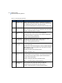
Installer menu option 2, Area Database
Each area can be programmed with a number of options, such as the area name, entry and
exit times, and event flags.
Use the following steps to navigate to the option:
1. Press [MENU*] enter 1278 and press [ENTER] to access the system menu.
2. Enter 19 and press [ENTER] to access menu 19, Installer Programming.
3. Press [MENU*] to choose advanced menu.
4. Enter 2 and press [ENTER] to access option 2, Area Database.
Note:
To program a YES/NO option, press [ENTER] to accept the display or press [MENU*] to
toggle between YES and NO. Enter 0 to skip options.
Select area to program
Area Database
Area No:
Enter the area number and press [ENTER].
Chapter 3
Programming details
Area name
Every area can be programmed with a name to identify the area. The words are selected
from the word library or from custom programmed text (see Installer menu option 10,
Program Text on page 15). The display shows the current area name, preceded by its
reference number.
Area Name: 0260 Workshop
Text No:
Enter the reference number for the area text name and press [ENTER].
Exit time
Every area has its own exit timers. Exit timers allow users arming an area, to leave the
premises, without generating an alarm (using access or entry/exit zones). Only after the exit
timers have expired, can an alarm occur.
Area 1:>Exit –Time 30 Entry Time 30
Exit time:
Each area can be programmed with one exit time. The exit times apply to all entry/exit or
access zone types (3, 4, 13, 14, 41 and 42). The entry time can only be started with entry/exit
zone types (3, 13, 41 and 42).
The exit timers can be programmed from 0 to 255 seconds.
Area 1:>Exit Time 30 Entry Time 30
Entry time:
Note:
If zones are assigned to more than one area, the longest exit time is used.
Enter the exit time and press [ENTER].
Entry time
Every area has its own entry timers. When entering the premises via an entry/exit zone, the
entry time starts. A user can disarm the area while the entry time is running without
generating an alarm.
33
34
Alliance System
Advanced Programming Manual
Each area can be programmed with one entry time. The entry times apply to all entry/exit or
access zone types (3, 4, 13, 14, 41 and 42). The entry time can only be started with entry/exit
zone types (3, 13, 41 and 42).
The entry timers can be programmed from 0 to 255 seconds.
Note:
If zones are assigned to more then one area, the longest entry and exit time is used.
Enter the entry time and press [ENTER].
Area event flags
Areas are capable of triggering event flags. Area event flags are different from event flags in
the zone database. Area event flags are triggered by an area event, not from a particular zone
event.
Example: To bypass an area number:
•
•
Activate an event flag number.
Trigger an output.
To program area event flags do the following:
1. Choose an event flag number from 0 through 255.
2. Record the event flag description for the chosen number on your system plan.
3. In Installer menu option 16, Event to Output on page 110 do the following:
•
•
•
Select an output event flag number.
Choose the event flag number that will trigger this output.
Select a time zone to control the output.
External siren event flag
This event flag is triggered when a zone generates an alarm (if the zone’s external siren
event flag set to YES). Each area can have its own external siren, using different event flags
for each area.
Area 1 External Siren Event Flag 1
Event Flag:
Enter the event flag number and press [ENTER]. Event flag 1 is selected by default.
Chapter 3
Programming details
If no change is needed, press [ENTER] to go to the next option.
Internal siren event flag
This event flag is triggered when a zone generates an alarm (if the zone’s internal siren event
flag set to YES). Each area can have its own internal siren, using different event flags for
each area.
Area 1 Internal Siren Event Flag 13
Event Flag:
Enter the event flag number and press [ENTER]. Event flag 13 is selected by default.
If no change is needed, press [ENTER] to go to the next option.
Area disarmed event flag
This event flag actives when the area is disarmed.
Area 1 Disarmed No Event Flag
Event Flag:
Enter the event flag number and press [ENTER].
If no event flag is needed, press [ENTER] to go to the next option.
Area active event flag
This event flag indicates if any zone in the area is active, excluding zones that can be used to
change the status of an area, used for cameras or are zone type “Unused”.
Area 1 Active No Event Flag
Event Flag:
Enter the event flag number and press [ENTER].
If no event flag is needed, press [ENTER] to go to the next option.
35
36
Alliance System
Advanced Programming Manual
Bypassed event flag
A zone in this area has been bypassed.
Area 1 Bypassed No Event Flag
Event Flag:
Enter the event flag number and press [ENTER].
If no event flag is needed, press [ENTER] to go to the next option.
Armed alarm event flag
This event flag activates on an alarm when the area is armed.
Area 1 Armed Alarm No Event Flag
Event Flag:
Enter the event flag number and press [ENTER].
If no event flag is needed, press [ENTER] to go to the next option.
Disarmed alarm event flag
This event flag activates on an alarm when the area is disarmed.
Area 1 Disarmed Alarm No Event Flag
Event Flag:
Enter the event flag number and press [ENTER].
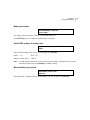
If no event flag is needed, press [ENTER] to go to the next option.
Chapter 3
Programming details
Local alarm event flag
This event flag activates on local alarms from 24-hour local fail zone types (15, 16, 18, 21,
30, 41, 42, 44, and 56) in the area.
Area 1 Local Alarm No Event Flag
Event Flag:
Enter the event flag number and press [ENTER].
If no event flag is needed, press [ENTER] to go to the next option.
Exit timer event flag
This event flag activates when the exit time for the area is running.
Area 1 Exit Timer No Event Flag
Event Flag:
Enter the event flag number and press [ENTER].
If no event flag is needed, press [ENTER] to go to the next option.
Entry timer event flag
This event flag activates when an entry time for the area is running.
Area 1 Entry Timer No Event Flag
Event Flag:
Enter the event flag number and press [ENTER].
If no event flag is needed, press [ENTER] to go to the next option.
37
38
Alliance System
Advanced Programming Manual
Warning time event flag
This event flag activates to indicate that an alarm group restriction is running and the area is
about to be armed or that a test mode is in progress and the test is about to end.
Area 1 Warning Time No Event Flag
Event Flag:
Enter the event flag number and press [ENTER].
If no event flag is needed, press [ENTER] to go to the next option.
Camera event flag
This event flag activates when a zone with the camera event flag set to YES generates an
alarm and the area is disarmed. Reset the camera event flag by pressing
[ENTER] [ENTER] 0 [ENTER].
Area 1 Camera No Event Flag
Event Flag:
Enter the event flag number and press [ENTER].
If no event flag is needed, press [ENTER] to go to the next option.
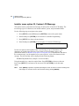
Prealarm timer event flag
This event flag indicates that a delayed disarmed alarm zone is active and the delay time is
running.
Area 1 Pre-Alarm Timer No Event Flag
Event Flag:
Enter the event flag number and press [ENTER].
If no event flag is needed, press [ENTER] to go to the next option.
Chapter 3
Programming details
Antimask event flag
This event flag is used with PIR detectors and forces the user to test the detectors before the
area can be armed. If an attempt to arm an area that has the antimask flag set to a nonzero
value and any area inputs are active, the event flag is set for 5 minutes. The antimask flag is
active for the duration of the timer and is reset when either the time elapses or the area is
successfully armed.
Area 1 Anti-Mask No Event Flag
Event Flag:
Enter the event flag number and press [ENTER].
If no event flag is needed, press [ENTER] to go to the next option.
Note:
There are no antimask event flags set in the area’s default settings.
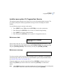
Latched reset event flag
This event flag is triggered when two valid disarm codes are entered for an area within five
minutes and the area is disarmed. The event flag is set for five seconds. For a further four
seconds, the area’s zone input type 67 (Latched Detector) is disabled. Latched Detector is a
24-hour, alarm-conditional, nine-second timer bypass input.
Area 1 Latched Reset No Event Flag
Event Flag:
Enter the event flag number and press [ENTER].
If no event flag is needed, press [ENTER] to go to the next option.
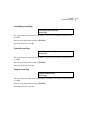
Alarm-A event flag
This event flag generates an event link to a relay output. The event flag follows the “A”
event generated by the AB alarms as sent to the central station event out queue.
Area 1 Alarm-A No Event Flag
Event Flag:
Enter the event flag number and press [ENTER].
39
40
Alliance System
Advanced Programming Manual
If no event flag is needed, press [ENTER] to go to the next option.
Alarm-B event flag
This event flag generates an event link to a relay output. The event flag follows the “B”
event generated by the AB alarms as sent to the central station event out queue.
Area1 Alarm-B No Event Flag
Event Flag:
Enter the event flag number and press [ENTER].
If no event flag is needed, press [ENTER] to go to the next option.
Out-of-hours time zone
This time zone is used to generate a report if the area is disarmed while the area should be
armed. The message is reported depending on the type of transmission protocol.
Out-of-Hour Time Zone: 0
Enter TZ:
Enter the time zone number and press [ENTER].
Area disarmed time
When using alarm group restrictions, one of the options available is to disarm an area for a
disarmed period. If the area disarmed time is not ‘0’, then this time will be used.
Area Disarmed Time: 0 Mins
Enter Mins:
Enter the minutes and press [ENTER].
Chapter 3
Programming details
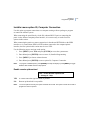
Report to central station 1
YES - Report to CS1
* - Change, 0 - Skip
YES
Report opening/closing and late-to-close to central station 1.
NO
Do not report to central station 1.
Report to central station 2
NO - Report to CS2
* - Change, 0 - Skip
YES
Report opening/closing and late-to-close to central station 2.
NO
Do not report to central station 2.
Report to central station 3
NO - Report to CS3
* - Change, 0 - Skip
YES
Report opening/closing and late-to-close to central station 3.
NO
Do not report to central station 3.
Report to central station 4
NO - Report to CS4
* - Change, 0 - Skip
YES
Report opening/closing and late-to-close to central station 4.
NO
Do not report to central station 4.
41
42
Alliance System
Advanced Programming Manual
Enable audio listen-In
NO - Enable Audio Listen-In
* - Change, 0 - Skip
YES
Enable audio listen-in.
NO
Do not enable audio listen-in.
Enable exit faults
Exit faults occur when an access zone or exit zone is still open at the moment the exit time
expires. On an exit fault a local alarm is generated and a special exit fault is reported to the
central station.
NO - Enable Exit Faults
* - Change, 0 - Skip
YES
Enable exit fault reporting.
NO
Do not enable exit fault reporting.
A&B alarm reporting (ACPO)
NO - A&B Alarm Reporting (ACPO)
* - Change, 0 - Skip
This option is not applicable to the US market.
Disable arming if all bypassed
YES - Disable Arming If All Bypassed
* - Change, 0 - Skip
YES
No arming available when all zones in the area are bypassed.
NO
Arming is available when all zones in the area are bypassed.
Chapter 3
Programming details
Keybox time
KeyBox Time: 0 Mins
Enter Mins:
Keybox time extends the exit time. Immediately after the exit timer expires, the keybox
timer starts for the specified keybox time. Close the zone before this additional keybox timer
expires. If it is not closed, a full alarm will be triggered again even if the previous trigger
was also an alarm. During the interval including both the exit timer and the keybox timer,
openings and closings will not be registered and will not cause an alarm.
Enter the keybox time and press [ENTER]. If no change is needed, press [ENTER] to go to
the next option.
Tamper alarm event flag
Area 1 Tamper Alarm No Event Flag
Event Flag:
The tamper alarm event flag becomes active whenever a tamper alarm is detected on an
input associated with the specific area, and is independent of arming state.
Enter the event flag number and press [ENTER]. If no event flag is needed, press [ENTER]
to exit.
43
44
Alliance System
Advanced Programming Manual
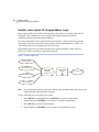
Installer menu option 5, Alarm Groups
Alarm groups enable users, zones, and arming stations to control the system’s alarm
functions (also called alarm control).
An alarm groups’s functionality is controlled by the following:
•
•
•
•
Areas—determines the areas you want this alarm group to control.
Time zone—determines the time zone applicable to this alarm group. Functions
assigned via this alarm group will be applicable only for the periods allowed by the
time zone. Also, both a user’s alarm group time zone and the RAS’s (or door’s)
alarm group time zone have to be valid.
Menus—determines access to the Alliance system menus that the user will have for
this alarm group.
Options—determines access to system functions that the user or RAS will have for
this alarm group. If you do not select User Alarm Group, then you will not be able to
attach the alarm group to any user.
See Table 7, Alliance system menus and options provided for alarm groups on page 45 for
details of the default settings for alarm groups.
Alarm groups are assigned to users, and to each piece of equipment on which the user
performs a function (arming stations, doors 17 to 64, and area control zone types 6, 31, 34
and 35). This provides enormous flexibility when determining a user’s access to, and control
of, the system.
Note:
You must be extremely careful when changing alarm groups. Both the functions performed by
user in the alarm group and the functions available at remote arming stations and door readers
with that alarm group will be affected.
A function that is provided to users via their alarm group is only valid when:
•
Program settings in other sections of the same alarm group allow it.
Example: Restricting alarm system control to reset only would be invalid unless the
alarm group has been allowed alarm system control. If the Restriction Reset Only is
set to YES, Alarm System Control must be set to YES.
•
The user’s alarm group has the same program setting as the alarm group of the RAS
or door the user is using.
Chapter 3
Programming details
Example: If the Prompt with List of Areas is set to YES in the user’s alarm group, it
must also be set to YES in the alarm group of the RAS or door. If it is not, areas are
not listed when arming/disarming.
•
The user’s alarm group includes the areas assigned to the alarm group of the RAS or
door the user is using.
Example: If a user’s alarm group has areas 1, 2, and 3 and the alarm group of the
RAS or door has areas 2 and 3, only the functions for areas 2 and 3 are valid.
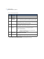
Alarm group default settings
Alarm groups 1 to 10 are hard coded into the system. They can be viewed but cannot be
changed since they contain master control and default settings. Many alarm groups have
default settings for system menus (see System menus on page 59) and alarm group options.
The default menus and options provided for each alarm group is listed in Table 7.
Table 7.
Alliance system menus and options provided for alarm groups
AG number
1
Name
No Access
Editable? Alliance system menus and options (defaults)
No
Menus: None
Option: User Alarm Group
2
Master RAS or Door
No
Menus: All
Options:
• Alarm System Control
• List of Areas
• Keypad Duress
• Reset System Alarms
• Modem Access
• Alarm Group Restriction 1
• Alarm Group Restriction 2
• Alarm Group Restriction 3
• Alarm Group Restriction 4
• Alarm Group Restriction 5
• Alarm Group Restriction 6
• Alarm Group 7 – Emergency
• Alarm Group 8 – Counter
45
46
Alliance System
Advanced Programming Manual
Table 7.
Alliance system menus and options provided for alarm groups (continued)
AG number
Name
Editable? Alliance system menus and options (defaults)
3
Master Code
No
Menus: All
Options:
• Alarm System Control
• List of Areas
• Keypad Duress
• Reset System Alarms
• Modem Access
4
8 Area RAS (1-8)
No
Menus: All
Options:
• Alarm System Control
• List of Areas
• Keypad Duress
• Reset System Alarms
• Modem Access
• Alarm Group Restriction 1
• Alarm Group Restriction 2
• Alarm Group Restriction 3
• Alarm Group Restriction 4
• Alarm Group Restriction 5
• Alarm Group Restriction 6
• Alarm Group 7 – Emergency
Chapter 3
Programming details
Table 7.
Alliance system menus and options provided for alarm groups (continued)
AG number
Name
Editable? Alliance system menus and options (defaults)
5
8 Area RAS (9-16)
No
Menus: All
Options:
• Alarm System Control
• List of Areas
• Keypad Duress
• Reset System Alarms
• Modem Access
• Alarm Group Restriction 1
• Alarm Group Restriction 2
• Alarm Group Restriction 3
• Alarm Group Restriction 4
• Alarm Group Restriction 5
• Alarm Group Restriction 6
• Alarm Group 7 – Emergency
6
Master Installer
No
Menus: All except 19
Options:
• Alarm System Control
• List of Areas
• Keypad Duress
• Modem Access
7
Manager
No
Menus: All except 19
Options:
• User Alarm Group
• Alarm System Control
• List of Areas
• Keypad Duress
• Reset System Alarms
• Modem Access
8
Spare
No
Menus: 1, 2, 3, 4, 5, 6, 7, 12, 13, 15, 19, 20, 21, 22,
23, 24
Options: None
47
48
Alliance System
Advanced Programming Manual
Table 7.
Alliance system menus and options provided for alarm groups (continued)
AG number
Name
9
Master Service
Editable? Alliance system menus and options (defaults)
No
Assigned time zone 25
Menus: 1, 2, 3, 4, 5, 6, 7, 12, 13, 15, 19, 20, 21, 22,
23, 24
Options:
• User Alarm Group
• Keypad Duress
• Reset System Alarms
• Modem Access
10
Spare
No
Menus: None
Options: None
11
12
High Level User
Master
Low Level User Master
Yes
Menus: All except 19
Options:
• Alarm System Control
• List of Areas
• Keypad Duress
• Reset System Alarms
Yes
Menus: 2, 3, 4, 6, 7, 8, 12, 13, 17, 18, 19, 20, 21,
22, 23, 24
Options:
• Alarm System Control
• List of Areas
• Keypad Duress
13
All Area User Code
Yes
Menus: 2, 3, 4, 6, 7, 8, 12, 13, 14, 15, 16, 17, 18,
19, 20, 21, 22, 23, 24
Options:
• Alarm System Control
• List of Areas
• Keypad Duress
Chapter 3
Programming details
Table 7.
Alliance system menus and options provided for alarm groups (continued)
AG number
14
Name
Area 1
Editable? Alliance system menus and options (defaults)
Yes
Menus: 2, 3, 4, 6, 7, 8, 12, 13, 14, 15, 16, 17, 18,
19, 20, 21, 22, 23, 24
Options:
• User Alarm Group
• Alarm System Control
• Keypad Duress
15
Area 2
Yes
Menus: 2, 3, 4, 6, 7, 8, 12, 13, 14, 15, 16, 17, 18,
19, 20, 21, 22, 23, 24
Options:
• Alarm System Control
• Keypad Duress
16
Area 3
Yes
Menus: 2, 3, 4, 6, 7, 8, 12, 13, 14, 15, 16, 17, 18,
19, 20, 21, 22, 23, 24
Options:
• Alarm System Control
• Keypad Duress
17
Area 4
Yes
Menus: 2, 3, 4, 6, 7, 8, 12, 13, 14, 15, 16, 17, 18,
19, 20, 21, 22, 23, 24
Options:
• Alarm System Control
• Keypad Duress
18
Area 5
Yes
Menus: 2, 3, 4, 6, 7, 8, 12, 13, 14, 15, 16, 17, 18,
19, 20, 21, 22, 23, 24
Options:
• Alarm System Control
• Keypad Duress
19
Area 6
Yes
Menus: 2, 3, 4, 6, 7, 8, 12, 13, 14, 15, 16, 17, 18,
19, 20, 21, 22, 23, 24
Options:
• Alarm System Control
• Keypad Duress
49
50
Alliance System
Advanced Programming Manual
Table 7.
Alliance system menus and options provided for alarm groups (continued)
AG number
20
Name
Area 7
Editable? Alliance system menus and options (defaults)
Yes
Menus: 2, 3, 4, 6, 7, 8, 12, 13, 14, 15, 16, 17, 18,
19, 20, 21, 22, 23, 24
Options:
• Alarm System Control
• Keypad Duress
21
Area 8
Yes
Menus: 2, 3, 4, 6, 7, 8, 12, 13, 14, 15, 16, 17, 18,
19, 20, 21, 22, 23, 24
Options:
• Alarm System Control
• Keypad Duress
22
Area 9
Yes
Menus: 2, 3, 4, 6, 7, 8, 12, 13, 14, 15, 16, 17, 18,
19, 20, 21, 22, 23, 24
Options:
• Alarm System Control
• Keypad Duress
23
Area 10
Yes
Menus: 2, 3, 4, 6, 7, 8, 12, 13, 14, 15, 16, 17, 18,
19, 20, 21, 22, 23, 24
Options:
• Alarm System Control
• Keypad Duress
24
Area 11
Yes
Menus: 2, 3, 4, 6, 7, 8, 12, 13, 14, 15, 16, 17, 18,
19, 20, 21, 22, 23, 24
Options:
• Alarm System Control
• Keypad Duress
25
Area 12
Yes
Menus: 2, 3, 4, 6, 7, 8, 12, 13, 14, 15, 16, 17, 18,
19, 20, 21, 22, 23, 24
Options:
• Alarm System Control
• Keypad Duress
Chapter 3
Programming details
Table 7.
Alliance system menus and options provided for alarm groups (continued)
AG number
26
Name
Area 13
Editable? Alliance system menus and options (defaults)
Yes
Menus: 2, 3, 4, 6, 7, 8, 12, 13, 14, 15, 16, 17, 18,
19, 20, 21, 22, 23, 24
Options:
• Alarm System Control
• Keypad Duress
27
Area 14
Yes
Menus: 2, 3, 4, 6, 7, 8, 12, 13, 14, 15, 16, 17, 18,
19, 20, 21, 22, 23, 24
Options:
• Alarm System Control
• Keypad Duress
28
Area 15
Yes
Menus: 2, 3, 4, 6, 7, 8, 12, 13, 14, 15, 16, 17, 18,
19, 20, 21, 22, 23, 24
Options:
• Alarm System Control
• Keypad Duress
29
Area 16
Yes
Menus: 2, 3, 4, 6, 7, 8, 12, 13, 14, 15, 16, 17, 18,
19, 20, 21, 22, 23, 24
Options:
• Alarm System Control
• Keypad Duress
30 to 138
Program as needed
Yes
Program as needed
51
52
Alliance System
Advanced Programming Manual
Programming alarm groups
Use the following steps to navigate to the option:
1. Press [MENU*] enter 1278 and press [ENTER] to access the system menu.
2. Enter 19 and press [ENTER] to access menu 19, Installer Programming.
3. Press [MENU*] to choose advanced menu.
4. Enter 5 and press [ENTER] to access option 5, Alarm Groups.
Note:
To program a YES/NO option, press [ENTER] to accept the display or press [MENU*] to toggle
between YES and NO. Enter 0 to skip options.
Alarm group number
Alarm Group **WARNING**
Alm-Grp:
Every alarm group has a number in the range 1 to 138.
Enter the alarm group number and press [ENTER].
Alarm group name
Program a name (or use the default name, if applicable) to identify the alarm group from the
text word library (see Installer menu option 10, Program Text on page 15).
Alm/Grp Name: 0297, Engineering
Text No:
Enter the reference number for the alarm group and press [ENTER]. The display shows the
current alarm group name, preceded by its reference number.
Areas assigned
1,2,3,5,7,8,9,
Area:
Enter the area numbers to be controlled by the alarm group (an alarm group can only control
the functions of areas that are assigned to it) and press [ENTER].
Chapter 3
Programming details
User alarm group
YES - Can This GRP Be Assigned to Users
* - Change, 0 - Skip
YES
This alarm group can be assigned to users.
NO
This alarm group is only assigned to a zone, door, or RAS.
Note:
Note An alarm group is only displayed in User Codes when the user who is creating a new user
has at least the same options (includes check of alternate alarm group). A user cannot create a
code for another user who has a higher security clearance.
Alarm system control
NO - Alarm System Control
* - Change, 0 - Skip
YES
Enable alarm system control. Users, doors, or RAS can arm or disarm the areas in
the alarm group. This option must be set to YES if any of the alarm group
restrictions in the alarm group are set to YES.
NO
Do not enable alarm system control. Access control functions and user menu
options specified are still valid.
List of areas
NO - Prompt With List of Areas
* - Change, 0 - Skip
YES
After the user has entered a PIN code and pressed [ON] or [OFF], the areas
assigned to the user are displayed. The user can then select from the arm/disarm
options.
NO
The areas assigned to the user are not displayed. Areas are immediately armed/
disarmed once the user has entered a PIN code and pressed [ON] or [OFF].
53
54
Alliance System
Advanced Programming Manual
Keypad duress
NO - Can User Activate Keypad Duress
* - Change, 0 - Skip
YES
A duress code can be entered on a keypad to activate a duress alarm.
NO
Duress cannot be activated. A duress code is treated as an invalid code.
Note:
See Duress mode on page 135 for duress code definitions.
Reset system alarm
NO - Reset System Alarms
* - Change, 0 - Skip
YES
A user with this alarm group can reset the latching system alarms. Alarm System
Control and Latching Systems Alarms must also be set to YES.
NO
A user cannot reset latching system alarms.
Disable auto unbypass
NO - Disable Auto-Unbypass
* - Change, 0 - Skip
YES
Disarming the area will not automatically unbypass zones in the area.
NO
Disarming the area will automatically unbypass zones.
Arm and reset only
NO - Restricted to Arm & Reset
* - Change, 0 - Skip
YES
Only arm and reset are allowed. Alarm system control must also be set to YES.
NO
There are no alarm control restrictions.
Chapter 3
Programming details
Disarm only
NO - Restricted to Disarm Only
* - Change, 0 - Skip
YES
Only disarm is allowed. Alarm system control must also be set to YES.
NO
There are no alarm control restrictions.
Alarm reset only
NO - Restricted to Reset Only
* - Change, 0 - Skip
YES
Only alarm reset is allowed. Alarm system control must also be set to YES.
NO
There are no alarm control restrictions.
Auto bypass active zones
NO - Auto Bypass Active Zones
* - Change, 0 - Skip
YES
When the arming starts, all active zones are automatically bypassed and the system
is armed without causing an alarm. Alarm System Control must also be set to YES.
NO
The system cannot be armed if there are active zones, unless Forced Arming is set to
YES.
Forced arming when zones active
NO - Forced Arming When Zones Active
* - Change, 0 - Skip
YES
The check for active zones is ignored and if there are active zones when the arming
procedure is started, the system still arms (the zones remain active and might cause
an alarm.
NO
The system cannot be armed if there are active zones, unless auto bypass is set to
YES.
55
56
Alliance System
Advanced Programming Manual
Prevent forced disarming
NO - Prevent Forced Disarming
* - Change, 0 - Skip
YES
Areas cannot be disarmed if there are type 1 or type 11 active zones.
NO
Areas can be disarmed if there are type 1 or type 11 active zones.
Modem access
NO - Can User Access Via Modem
* - Change, 0 - Skip
YES
Enables modem access with a VT100 terminal by a user with this alarm group. RAS
16 must have a suitable alarm group assigned to specify the functions available.
This option does not apply to upload/download software.
NO
Modem access with a VT100 terminal is not allowed by a user with this alarm
group.
Chapter 3
Programming details
Alarm group restrictions (1 through 8)
NO - User Has Alm/Grp Restriction 1
* - Change, 0 - Skip
These options give certain restrictions to alarm groups. Only one restriction is available per
alarm group, however every alarm group can use the same restriction. This section describes
the following alarm group restrictions:
•
•
•
•
•
•
•
•
Restriction 1 - Restrict alarm control to timed disarm or arm/reset.
Restriction 2 - Restrict alarm control to timed disarm or arm/reset.
Restriction 3 - Restrict alarm control to timed disarm or arm/reset.
Restriction 4 - Restrict alarm control to timed disarm or arm/reset.
Restriction 5 - Restrict alarm control to timed disarm or arm/reset.
Restriction 6 - Restrict alarm control to timed disarm or arm/reset.
Restriction 7 - Restrict alarm control to timed disarm or arm/reset, but on a timed
disarm report an emergency alarm when the area arms again.
Restriction 8 - Restrict alarm control to timed disarm or arm/reset, but on disarming
increase a counter. When the area is armed decrease the counter. When the counter
reaches 0, arm the areas in the alarm group.
YES
Activates the alarm group restrictions.
NO
The alarm group restrictions are not activated.
No arming if alarm group restriction not timing
NO - No Arming If Restr. Not Timing
*-Change, 0-Skip
YES
If an area has been disarmed and there is no alarm group restriction timer running,
an alarm group restriction timer cannot be started. When an alarm group restriction
timer expires, it arms an area. By setting this option, you prevent an area from being
armed if a user without alarm group restrictions originally has disarmed it.
NO
Normal alarm group restrictions apply.
57
58
Alliance System
Advanced Programming Manual
Change own PIN only
NO – Change Own PIN Only
* - Change, 0 - Skip
YES
Users with this alarm group are restricted so that they can change only their own
PIN codes.
NO
Users with this alarm group may change their own PIN codes plus the PIN codes of
any users that have the same alarm group or a subordinate alarm group. See
Glossary on page 242 for a definition of subordinate alarm group.
Note:
The ‘Change own PIN only’ option becomes available only when alarm group user menu option 14
‘Program Users’ is set to Yes (selected).
Allow stop voice reporting
NO – Allow Stop Voice Reporting
* - Change, 0 - Skip
This option, when set to YES for an alarm group assigned to both a user and an alarm group
assigned to a RAS, enables a user (referred to as an authorized user) to cancel active and
queued events from being reported via the voice reporting protocol (VR). This option does
not apply to panic, duress, or hold-up events.
YES
The user or RAS assigned with this alarm group is allowed to cancel active and
queued voice reporting events.
NO
The user or RAS is not allowed to stop the voice reporting.
When an authorized user disarms an area where VR dialer events are either active, or
queued, the following message is presented to the user:
Stop Voice Reporting
*-NO, #-YES:
A response is expected within 20 seconds, otherwise the question is removed from the RAS
display and panel operation continues assuming NO was selected.
Chapter 3
Programming details
It does not matter whether the area is armed or disarmed, i.e. an authorized user can initially
disarm the area and choose to not stop voice reporting (or fail to make a choice), then later
enter the disarm code again to choose to stop voice reporting.
System menus
NO - 1-Panel Status
*-Change 0-Skip
Determine if the system menu item is available in this alarm group to users or RAS.
Each system menu is displayed and must be set to YES for it to be available to the alarm
group. The system menus available for selection are:
1. Panel Status
13. Start Auto Disarm Test
2. Active Zones
14. Program Users
3. Zones in Alarm
15. Time & Date
4. Bypassed Zones
16. Bypass/Unbypass RAS/DGP
5. History
17. Enable/Disable Service Tech
6. Test Report
18. Reset Cameras
7. Service Menu
19. Installer Programming
8. Film Counters
20. Door and Floor Groups
9. List Zone Names
21. Holidays
10. Bypass Zone
22. Open Door
11. Unbypass Zone
23. Unlock, Lock, Disable and Enable
12. Test Zone
24. Print History
Alarm group time zone
Alm-Grp 14 Time Zone 4
Time Zone:
Determine the time zone that applies to this alarm group. The alarm group is only available
if the time zone is valid (see Installer menu option 13, Time Zones on page 29).
Enter the time zone number for this alarm group and press [ENTER].
59
60
Alliance System
Advanced Programming Manual
Alternate alarm group
Grp 14 Alt-Grp 12 – Night Shift
Alm-Grp:
You can program each alarm group to have an alternate alarm group. The alternate alarm
group is used whenever the original alarm group is disabled due to an invalid time zone. The
alternate alarm group can have different areas or options than the original alarm group.
Example: During normal working hours, users can arm and disarm from a list. After hours,
only arm/alarm reset is allowed without presenting a list of areas.
The alternate alarm group can also be programmed with an alternate alarm group and so on,
up to three alarm groups (the original plus two alternates). If a function is denied by the time
zone of one alarm group, the next will be checked, etc.
Note:
When alternate alarm groups are active and have alarm group restrictions, the alternate alarm
group restrictions apply. See Installer menu option 15, Alarm Group Restrictions on page 147.
Enter the alternate alarm group number for this alarm group and press [ENTER].
Arming and resetting alarms after regular hours (disarm inhibit)
1. Program the time zones for the users using Installer menu option 13, Time Zones.
2. Program the user alarm groups with options using Installer menu option 5, Alarm
Groups.
3. Program the first user alarm group with options for the users using Installer menu
option 5, Alarm Groups.
4. Program an alternate user alarm group using the option Arm and reset only in
Installer menu option 5, Alarm Groups. Assign the area and select the 24/7 time
zone.
5. Go back to the users alarm group and add alternate users alarm group using Installer
menu option 5, Alarm Groups.
6. Program the users with the selected user alarm groups using System menu option 14,
Program Users.
7. Select the users that will have the options to arm and reset the system after regular
hours using System menu option 14, Program Users.
Chapter 3
Programming details
Installer menu option 3, RAS Database
Remote Arming Stations (RAS) are devices used to provide system control, such as area
arming or disarming. Depending on the type of remote arming station, additional functions
can be available, such as LCD displays, menus to set time and date etc.
Use the following steps to navigate to the option:
1. Press [MENU*] enter 1278 and press [ENTER] to access the system menu.
2. Enter 19 and press [ENTER] to access menu 19, Installer Programming.
3. Press [MENU*] to choose advanced menu.
4. Enter 3 and press [ENTER] to access option 3, RAS Database.
Note:
To program a YES/NO option, press [ENTER] to accept the display or press [MENU*] to toggle
between YES and NO. Enter 0 to skip options.
Poll RAS
1,2,3:4,
Poll RAS:
In order to be used, a RAS has to be polled. Polling enables communication between the
RAS and the control panel. The display shows the RAS currently polled. A RAS number
followed by a “,” is online and will generate system and tamper alarms. A RAS number
followed by a “:” is offline and will not generate system and tamper alarms.
1. Enter the RAS number to be polled and press [ENTER]. Repeat for all RAS
numbers to be polled.
2. To deactivate a RAS number that is already polled, enter the RAS number again and
press [ENTER].
3. Press [ENTER] again to move to the next option.
61
62
Alliance System
Advanced Programming Manual
Select RAS to program
Arming Station Details
RAS No:
Enter the RAS number to be programmed and press [ENTER].
Area alarm group
RAS: 2 Alm-Grp: 2 Master RAS or Door
Alm-Grp:
Enter the alarm group number you want the RAS assigned to and press [ENTER]. This
defines the areas that the RAS can control. A user can only perform options on a RAS that
are allowed in both the RAS’s alarm group and the user’s alarm group.
Menu alarm group
RAS: 2 Alm-Grp: 2-Master RAS or Door
Menu Alm-Grp:
The menu alarm group determines which actions are allowed on a RAS. The menu alarm
group can also have more areas than the area alarm group. The user can have no alarm
control over those areas but can, for example, see the status of zones in these areas.
If the menu alarm group is programmed for alarm group 1 - No Access, then the arming
station will use the area alarm group as the menu alarm group.
Enter the menu alarm group and press [ENTER].
Chapter 3
Programming details
Door event flag
RAS: 2 Has No Door Event Flag
Event Flag:
If the RAS is used to unlock a door, assign a door event flag to the output. The door event
flag will be activated when a valid code is entered at the RAS. The code is determined by
the settings of Enter Key Opens Door Only and Alarm Code Prefix.
Enter the event flag number and press [ENTER].
Output controller
RAS: 2 Can See Output Controller 0
Output Ctrl:
Keypads with card reader interfaces have an output OUT. To be able to control the output, an
output control group has to be assigned to the RAS. The first output on the output controller
is also the OUT output from the RAS. Whenever the first output is activated, the OUT
output is also activated. If two RASes have the same output control group and the user’s
door group has both doors, both relays will be switched simultaneously.
Enter the output control group assigned to the RAS and press [ENTER].
RAS programming options
Program the RAS according to its characteristics (for example, if the RAS has an LCD
display, set the LCD Arming Station option to Yes. Refer to Table 8 for a list of the options
that may be programmed for each model of RAS.
63
64
Alliance System
Advanced Programming Manual
Table 8.
Programming options by RAS model
AL1103
AL1108
LCD arming station
Y
Y
Y
Y
N
N
N
N
Toggle area status
O
O
O
O
O
O
O
O
Enter key opens door only
O
O
O
O
O
O
O
O
Door event flags on alarm code
O
O
O
O
O
O
O
O
Display shunted zone on LC
O
O
O
O
N
N
N
N
Arm/disarm using one key
O#
O#
O#
O#
N
O#
O#
N
Cards auto disarm
N
O
N
O
N
N
O
O
Card always arms/disarms
N
O
N
O
N
N
O
O
Reset from RAS without cod
O
O
O
O
O
O
O
N
Programming function
AL1111
AL1116
AL1150
AL1151
AL1156
AL1197
Alarm group restrictions
disarm only
O
O
O
O
O
O
O
O
Entry/exit buzzer
O
O
O
O
O
O
O
O
Timed lockout
O
O
Cards arm after 3 badge
N
O
O
N
O
O
O
O
O
O
N
O
O
O
O
Disable status LED
O
O
O
O
O
O
3 LED RAS
N
N
N
N
N
Y
Card & PIN (disarm only
N
O
N
O
O
N
O
O
RAS tamper (ACPO) are
NA
NA
NA
NA
NA
NA
NA
NA
Y
O
O
Legend:
Y = Must be set to YES
N = Must be set to NO
O = Optional
NA = Not applicable to the US market.
# = CAUTION If an LCD arming station is used as master; and “Arm Using One Key” is set to YES;
the system must be programmed so that areas 9 to 16 can never be armed.
Chapter 3
Programming details
Details of RAS programming options follow.
LCD arming station
YES – LCD Arming Station
* - Change, 0 - Skip
YES
This RAS is an LCD arming station (must be set to YES to operate LCD arming
stations).
NO
This RAS is not an LCD arming station.
Toggle area status
NO – Code ENTER Toggles Area Status
* - Change, 0 - Skip
YES
The [ON] and [OFF] keys lose their function. For arm control the user must enter
the user code followed by [ON], [OFF], or [ENTER]. If a list of areas appears,
pressing the area number and [ENTER] toggles the status of the area. If no list
appears, the status of the areas is toggled immediately.
NO
Normal alarm control.
Note:
We recommend that you set this option to NO.
ENTER key opens door only
NO – ENTER Key Opens Door Only
* - Change, 0 - Skip
YES
The [ENTER] key unlocks the door but the [ON] and [OFF] keys are used for
alarm control.
NO
The [ENTER] key unlocks the door and also provides alarm control and resets
alarms.
Note:
Set this option to YES for the best user interface on LCD arming stations.
65
66
Alliance System
Advanced Programming Manual
Door event flag on alarm codes
NO – Door Event Flag On Alarm Codes
* - Change, 0 - Skip
YES
User codes with alarm control and door groups will unlock the door.
NO
User codes with alarm control will not unlock the door.
Display shunting on LCD
NO – Display Shunting on LCD
* - Change, 0 - Skip
YES
When a zone is shunted, the text ‘Zone Shunted’ will appear on the display.
NO
Nothing is shown when a zone is shunted.
Arm/disarm using one key
YES – Arm/Disarm Using One Key
* - Change, 0 - Skip
YES
After entering the user code, arm or disarm areas by entering the number of the area
without pressing [ENTER].
NO
Normal alarm control.
Note:
This option is only available for areas 1 through 8. If an LCD arming station is used as master;
and “Arm Using One Key” is set to YES; the system must be programmed so that areas 9 to 16
can never be armed.
Cards auto disarm
NO – Cards Auto Disarm
* - Change, 0 - Skip
YES
Cards disarm areas without using the [OFF] key.
NO
Only the door is unlocked, except if CardAlways Arms/Disarms is set to YES or the
[ON]/[OFF] key is used.
Chapter 3
Programming details
Cards always arm/disarm
NO – Cards Always Arm/Disarm
* - Change, 0 - Skip
YES
Cards arm/disarm alarm groups without using the [ON]/[OFF] keys. Toggles Area
Status must also be set to YES.
NO
Normal alarm control.
Note:
The card user's alarm group and the arming station's (reader's) alarm group must both allow arm
and/or disarm functions before a card can be used to arm/disarm.
Reset from RAS without code
NO – Reset From RAS Without Code
* - Change, 0 - Skip
YES
Reset alarms by pressing [ENTER] [ENTER] (show alarms) followed by 0
[ENTER]. The areas in alarm must be assigned to the RAS alarm group.
NO
Reset only with user code.
Alarm group restrictions disarm only
NO – AlmGrp Restriction Disarm Only
* - Change, 0 - Skip
YES
Users with alarm group restrictions can only disarm or delay automatic arming
(cannot be used for alarm group restrictions with arm and reset).
NO
There is no restriction.
67
68
Alliance System
Advanced Programming Manual
Enable entry/exit buzzers
YES – Entry/Exit Buzzers
* - Change, 0 - Skip
YES
Enable buzzer for entry/exit timers.
NO
No entry/exit timers on buzzer.
Note:
Entry time must be greater than 10 seconds.
Timed lockout
YES – Timed Lockout
* - Change, 0 - Skip
YES
On a code tamper, the RAS will lockout for 90 seconds.
NO
Only event reported. The RAS will be available.
Note:
A code tamper is five consecutive wrong codes.
Cards arm after three badges
NO – Cards Arm After 3 Badges
* - Change, 0 - Skip
YES
The assigned areas will arm with three badges of a valid card within 10 seconds.
NO
The assigned areas will arm with one badge of a valid card (if Cards auto disarm is
set to YES).
Disable status LEDs
NO – Disable Status LEDs
* - Change, 0 - Skip
This option disables the optical indicators on the bus device card readers. The option to
enable or disable the status LEDs must be set by the user because not all non-LCD bus
devices are card readers, therefore this option has to be set based on the hardware connected.
Chapter 3
Programming details
69
YES
The panel will not set any of the LED bits in the data packet. This will result in the
LEDs not being active.
NO
LEDs are not disabled.
Note:
Certain card reader settings override the status of command packet LED bits so that LEDs remain
illuminated even though LED bits are disabled. In order to use this feature, it may be necessary to
alter card reader configurations.
Three LED RAS
NO – 3 LED RAS
* - Change, 0 - Skip
YES
Allows configuration of LED operation if the RAS is a three LED RAS.
NO
Default operation.
Card & PIN (disarm only)
NO – Card & PIN (Disarm Only)
* - Change, 0 - Skip
YES
Both card and PIN are required to disarm the system.
NO
Default operation.
RAS tamper (ACPO) area
RAS Tamper (ACPO) Area 1
Area:
This option is not applicable to the US market. press [ENTER] to skip.
70
Alliance System
Advanced Programming Manual
Installer menu option 4, DGP Database
Data gathering panels (DGP) are devices used to send information in the system to the
control panel.
Use the following steps to navigate to the option:
1. Press [MENU*] enter 1278 and press [ENTER] to access the system menu.
2. Enter 19 and press [ENTER] to access menu 19, Installer Programming.
3. Press [MENU*] to choose advanced menu.
4. Enter 4 and press [ENTER] to access option 4, DGP Database.
Poll DGP
1,2,3:4
Poll DGP:
Each DGP must be polled to enable communication between the DGP and the control panel.
The display shows the DGP currently polled. A DGP number followed by a “,” is online and
can communicate with the control panel. A DGP number followed by a “:” is offline and
cannot communicate with the control panel.
Enter the DGP address number to be polled and press [ENTER]. Repeat for all DGP address
numbers to be polled.
Note:
The AL-1255 4-door DGP or AL-1265 4-elevator DGP must not be addressed higher than address
number 12.
To deactivate a DGP address number that is already polled, enter the DGP address number
again and press [ENTER].
Note:
Deactivating a DGP address number clears all alarms for zones and system points for that DGP
address. If the next DGP address number is not polled, alarms on any of the 32 zones that belong
to the DGP are cleared.
Press [ENTER] again to program the DGP type.
Chapter 3
Programming details
DGP type
Set DGP Type
DGP No:
Enter the DGP address number of the DGP to program and press [ENTER].
Standard
Type:
Enter the number for the type of DGP used at this address and press [ENTER].
Table 9.
DGP types
Number
Type
Alliance number
0
Standard DGP
AL-1205, AL-1206, AL-1210, AL-1220
1
4-Door DGP
AL-1255
2
4-Elevator DGP
AL-1265
3
Wireless DGP (319.5 MHz)
AL-1231
4
Point ID DGP
AL-1291
5
Advanced DGP
AL-1205
DGP tamper (ACPO) area
DGP Tamper (ACPO) Area 1
Area:
This option is not applicable to the US market. press [ENTER] to skip.
71
72
Alliance System
Advanced Programming Manual
Installer menu option 1, Zone Database
Each zone is a physical input on the control panel, a DGP, or a plug-in expander.
Note:
All zones used for safe or vault monitoring must be a 24-hour alarm zone type.
Use the following steps to navigate to the option:
1. Press [MENU*] enter 1278 and press [ENTER] to access the system menu.
2. Enter 19 and press [ENTER] to access menu 19, Installer Programming.
3. Press [MENU*] to choose advanced menu.
4. Enter 1 and press [ENTER] to access option 1, Zone Database.
Note:
To program a YES/NO option, press [ENTER] to accept the display or press [MENU*] to toggle
between YES and NO. Enter 0 to skip options.
Zone number
Zone Database
Zone:
Select the appropriate zone number to program. Every zone has a number between 1 and
256, depending on the location in the system.
Enter the zone number to be programmed and press [ENTER].
Zone name
1: Zone 1
TextWord 1:
Program a zone name to identify the zone on the RAS (for example, when an alarm has
occurred).
A zone name can consist of up to four text words from the text library, each separated by a
three-digit text variable number in the range 1 through 255, or a space. The complete name
can have up to 36 characters. See Installer menu option 10, Program Text on page 15 for
details.
For example, to add the zone name (Office 4 Door 1 Contact 2) for Zone 1:
Chapter 3
Programming details
73
1. Enter the text reference number for Office from the text library and press [Enter].
2. Enter the text variable number, 4, and press [ENTER].
3. Enter the text reference number for Door from the text library and press [ENTER].
4. Enter the text variable number, 1, and press [ENTER].
5. Enter the text reference number for Contact from the text library and press
[ENTER].
6. Enter the text variable number, 2, and press [ENTER].
7. Press [ENTER] again to save the information and move to the next option.
Zone type
Type 2, Armed Alarm
Type:
Enter the zone input type number (from Table 10, Zone input types) and press [ENTER].
The zone type determines exactly how the zone will function in given circumstances. Most
zone types require an area, but zone types that affect the status of areas (zone types 6, 31, 34,
35) need alarm groups.
Note:
The zone type is important and influences much of the programming and functions of the system.
You must be very careful when programming zone types.
Armed and Disarmed — An area may be armed or disarmed. If an area is armed, certain
zone types will go into alarm when the zone is activated. Other zone types only go into
alarm when the area is disarmed.
Tamper Alarms — When the dual zone option is set to YES, a short or open circuit on most
zone types will generate a tamper alarm. When set to NO, an open or short circuit is the
same as an activated zone. Zone types that are not used to generate alarms do not generate
tamper alarms.
Entry/Exit Times — Where entry/exit times are referred to, the time used is the longest
entry/exit time programmed for any of the areas assigned to the zone.
74
Alliance System
Advanced Programming Manual
Table 10. Zone input types
Number
Zone input type
Description
1
Disarmed alarm
Generates an alarm when the area is disarmed and reports it to the
central station.
Does not generate an alarm if the area is armed.
Example: hold-up button
2
Instant
Generates an alarm when the area is armed, does not generate an
alarm when the area is disarmed.
Example: internal door, PIR (motion detector)
3
Entry/exit alarm
Does not generate an alarm when the area is disarmed. Does not
generate an alarm when the entry or exit timer is running.
When the area is armed the exit timer starts. Activating the zone during
this interval will not generate an alarm. If the zone is activated after the
exit time has expired, then the entry timer starts. Activating the zone
during this interval will not generate an alarm. If the area is still
activated when the entry time expires, an alarm is generated.
Example: front door.
Note:
4
Interior follower
The entry/exit time must be programmed.
Does not generate an alarm when the area is disarmed.
Generates an alarm when the area is armed and the exit timer for the
zone has expired and the entry timer is not running.
Example: PIR at entrance.
Note:
5
24-hour alarm
The entry/exit time must be programmed.
Generates an alarm regardless of the status of the area.
Example: panel tampers, panic alarm.
61
Monitored key
switch
The programmed alarm group functions are performed when the zones
switches from normal to active. Also see footnote 1.
Example: key switch next to front door.
Chapter 3
Programming details
Table 10. Zone input types (continued)
Number
Zone input type
Description
72
Camera suspicion When the zone is activated, cameras in the areas assigned to the zone
will be activated. When the zone is deactivated, the cameras continue
to operate for the programmed suspicion time. Also see footnote 2.
Example: suspicion button.
Note:
8
Disarm delayed/
instant
The suspicion time must be programmed.
Generates an alarm when the area is disarmed but does not report it
to the central station until the delayed alarm timer has expired or a
second delayed alarm is activated.
Generates a general burglar arm when the area is armed.
Example: hold-up button on a counter where more than one hold-up
button is used.
Note:
9
Reset delayed
The disarmed alarm delay time must be programmed.
Resets a delayed alarm type if the zone switches to normal state.
Resets a delayed alarm type if the delay timer is still running (a full
alarm has not been activated).
Stops the cameras from operating if the zone is activated, but the
delayed time continues to run. Also see footnote 1.
Example: reset button for quick cancellation of alarm.
Note:
10
Do NOT Use
11
Disarm delayed
Delayed zone types are: 8, 11, 22, and 40.
Generates an alarm when the area is disarmed but does not report it
until the delayed alarm timer has expired or a second delayed alarm is
activated.
Does not generate an alarm if the area is armed.
Example: hold-up button.
Note:
12
Restart exit timer
The delayed alarm time must be programmed.
This is a pulsed key switch that resets the entry timers and restarts
the exit timers for all areas assigned to the zone. Also see footnote 1.
Example: key switch next to door.
75
76
Alliance System
Advanced Programming Manual
Table 10. Zone input types (continued)
Number
Zone input type
13
Entry/exit no
zone check
Description
Does not generate an alarm when the area is disarmed.
When the area is armed and the exit timer starts, activating the zone
will not generate an alarm. If the zone is activated and the exit time
has expired, the entry timer starts. When the exit time has expired,
an alarm will be generated.
Note:
14
Interior follower
no alm zone
check
The entry/exit time must be programmed.
Does not generate an alarm when the area is disarmed.
Generates an alarm when the area is armed and there is no active
entry/exit timer for the area.
The zone may be activated when arming the area.
Example: PIR in hallway.
Note:
15
Day/night
The entry/exit time must be programmed.
Generates a local alarm when the area is disarmed.
Automatically activates an audible alert on arming stations assigned
to the same areas. The only event flag activated is the zone event flag.
This local alarm can be reset by pressing, [ENTER] [ENTER] 0
[ENTER], or USER CODE [OFF] AREA [ENTER], on the arming
station to stop the audible alert and cancel the event.
If the zone remains activated, it generates a new local alarm after the
programmed local alarm reminder time.
Example: emergency exit.
Note:
16
24-hour local ac
fail
17
Do NOT Use
18
Report Fail
The local alarm reminder time must be programmed.
This zone is not used in standard commercial versions of Alliance
system control panels. It generates a local alarm and activates an
audible alert. Also see footnote 2.
Generates a local alarm. Activates an audible alert on arming stations
assigned to the same area.
Activates FAULT LED on all arming stations and generates LCD fault
display message. Also see footnote 2.
Chapter 3
Programming details
Table 10. Zone input types (continued)
Number
Zone input type
19
Silent trouble
Activates FAULT LED on all arming stations and generates LCD fault
display message. Also see footnote 1.
20
Zone to event
flag 24-hour
Activates the zone event flag when activated, opened, or shorted.
Day/night with
user code
Generates a local alarm when the area is disarmed, but does not
report it to the central station and no audible alert on arming stations.
21
Description
Example: doorbell.
This alarm can only be acknowledged by entering USER CODE [OFF]
AREA [ENTER] on the arming station.
Generates an alarm when the area is armed.
Example: emergency door.
22
Disarm delay
reset/instant
Generates an alarm when the area is disarmed but does not report to a
central station until the delayed alarm timer has expired or a second
delayed alarm is activated.
If the zone closes to normal state during the delayed time, it resets
automatically.
Generates an alarm when the area is armed.
Example: hold-up button.
Note:
23
Camera 1 count
The delayed alarm time must be programmed.
Used to increment the film counter for camera 1 by connecting a
normally open contact across the zone. The counter increments if
the zone switches from open to short. Also see footnote 1.
Can only be used with Alliance control panel zones (not DGP zones).
24
Camera 2 count
Used to increment the film counter for camera 2 by connecting a
normally open contact across the zone. The counter increments if
the zone switches from open to short. Also see footnote 1.
Can only be used with Alliance control panel zones (not DGP zones).
25
Camera 3 count
Used to increment the film counter for camera 3 by connecting a
normally open contact across the zone. The counter increments if the
zone switches from open to short. Also see footnote 1.
Can only be used with Alliance control panel zones (not DGP zones).
77
78
Alliance System
Advanced Programming Manual
Table 10. Zone input types (continued)
Number
Zone input type
26
Camera 4 count
Description
Used to increment the film counter for camera 4 by connecting a
normally open contact across the zone. The counter increments if the
zone switches from open to short. Also see footnote 1.
Can only be used with Alliance control panel zones (not DGP zones).
27
Communicator
only
When the zone is activated, opened, or shorted, it reports to the central
station. A restore is sent when the zone deactivates. Also see footnote 2.
Example: temperature alarm on freezer.
28
Instant with auto
reset
Does not generate an alarm when the area is disarmed.
Generates an alarm when the area is armed. Resets automatically
when the zone closes to normal state.
Example: latching glassbreak detector.
29
24-hour alarm
with auto reset
Generates an alarm regardless of the status of the area. Resets
automatically when the zone closes to normal state.
Example: latching glassbreak detector.
30
Day/night with
auto reset
Generates a local alarm when the area is disarmed but does not report
it to the central station.
This alarm can only be acknowledged by entering, USER CODE [OFF]
AREA [ENTER], on the arming station. If the zone closes to normal
state, the alarm is reset.
Generates an alarm when the area is armed.
Example: emergency door.
31
Latching key
switch
Used to arm or disarm areas. When the zones switches to active, the
areas arm. When the zones switches to normal state, the areas disarm.
This zone types uses an alarm group to perform the arm/disarm
functions. Also see footnote 1.
Example: latching key switches to arm/disarm areas.
Note:
32
Armed zone to
event flag
The alarm groups must be programmed.
Does not perform any action when the area is disarmed.
Activates the zone event flag when the area is armed.
Example: temperature alarm on freezer activates buzzers.
Chapter 3
Programming details
Table 10. Zone input types (continued)
Number
Zone input type
33
24-hour alarm &
bypass
Description
This zone type requires different wiring. The zone can have the
following states:
• Shorted – generates an alarm
• Normal – no alarm
• Active – bypass (no alarm generated)
• Open – tamper alarm
Example: A key switch is used to bypass the zone in shopping centers
where only one zone is available for each shop.
34
Area disarm/
alarm group
restriction
A latching key switch that has a special function:
• Switching from normal state to active starts the warning time for
the alarm group restriction assigned to the alarm group. When the
warning time expires, the area arms.
• Switching from active to normal state disarms the areas.
Example: key switch in a large building that indicates the area is going
to arm. Also see footnote 1.
Note:
35
The alarm groups, alarm group restrictions, and a warning
time must be programmed.
Area alarm group A latching key switch that has a special function:
restriction arm
• Switching from normal state to active starts the warning time for
only
the alarm group restriction assigned to the alarm group. When the
warning time expires, the area arms.
• Switching from active to normal state does not perform any action.
Example: key switch in a large building that indicates the area is going
to arm. Also see footnote 1.
Note:
36
Camera 5 count
The alarm groups, alarm group restrictions, and a warning
time must be programmed.
Used to increment the film counter for camera 5 by connecting a
normally open contact across the zone. The counter increments if the
zone switches from open to short.
Can only be used with Alliance control panel zones (not DGP zones).
Also see footnote 1.
79
80
Alliance System
Advanced Programming Manual
Table 10. Zone input types (continued)
Number
Zone input type
37
Camera 6 count
Description
Used to increment the film counter for camera 6 by connecting a
normally open contact across the zone. The counter increments if the
zone switches from open to short.
Can only be used with Alliance control panel zones (not DGP zones).
Also see footnote 1.
38
Camera 7 count
Used to increment the film counter for camera 7 by connecting a
normally open contact across the zone. The counter increments if the
zone switches from open to short.
Can only be used with Alliance control panel zones (not DGP zones).
Also see footnote 1.
39
Camera 8 count
Used to increment the film counter for camera 8 by connecting a
normally open contact across the zone. The counter increments if the
zone switches from open to short.
Can only be used with Alliance control panel zones (not DGP zones).
Also see footnote 1.
40
Entry/exit day
night
If the area is disarmed it has the following functions:
• Shorted – Activates cameras in the areas that are assigned to the
zone. When the zone switches back to normal, the cameras
continue to operate for the suspicion time.
• Normal – No alarm.
• Active – Generates an alarm but does not report to the central
station until the delayed alarm timer has expired or a second
delayed alarm is activated.
• Open – Tamper.
Generates a general burglar alarm when the area is armed.
Note:
The delayed alarm time must be programmed.
Chapter 3
Programming details
Table 10. Zone input types (continued)
Number
Zone input type
41
Entry/exit day
night with coder
Description
Generates a local alarm when the area is disarmed.
Automatically activates an audible alert on arming stations assigned to
the same areas. The only event flag activated is the zone event flag.
This local alarm can be reset by entering, [ENTER] [ENTER] 0
[ENTER], or, USER CODE [OFF] AREA [ENTER], on the arming
station to stop the audible alert and cancel the event.
If the zone remains activated, it generates a new local alarm after the
programmed local alarm reminder time.
When the area is armed, the exit timer starts and activating the zone
will not generate an alarm. If the zone is activated and the exit time
has expired, the entry timer starts. When the exit time has expired, an
alarm will be generated.
Example: emergency door that is also used to enter the premises.
Note:
42
Entry/exit fire
door with code
The entry/exit timer and the local alarm reminder time must
be programmed.
Generates a local alarm when the area is disarmed but does not report
it to the central station.
This local alarm can only be acknowledged by entering, USER CODE
[OFF] AREA [ENTER], on the arming station.
When the area is armed, the exit timer starts and activating the zone
will not generate an alarm. If the zone is activated and the exit time
has expired, the entry timer starts. When the exit time has expired, an
alarm will be generated.
Example: emergency door that is also used to enter the premises.
Note:
43
Day/night zone
to event flag
The entry/exit timer must be programmed.
Activates the zone event when the area is disarmed.
Does not perform any action when the area is armed.
Example: opening a closet activates a buzzer.
81
82
Alliance System
Advanced Programming Manual
Table 10. Zone input types (continued)
Number
Zone input type
44
Day/night with
alarm group
restriction
Description
Generates a local alarm when the area is disarmed but does not report
it to the central station.
This local alarm can only be acknowledged by entering, USER CODE
[OFF] AREA [ENTER], on the arming station.
Generates an alarm when the area is armed but the zone can be
disabled when two users with alarm group restrictions have entered
their user code (not necessarily in the same area).
Example: emergency door.
Note:
45
Disarm event
Activates the zone event when the area is disarmed.
flag/armed alarm Generates an alarm when the area is armed, but the zone can be
with restriction
disabled if two users with alarm group restrictions have entered their
user code (not necessarily in the same area).
Note:
46
47
The alarm groups and alarm group restrictions must be
programmed.
The alarm groups and alarm group restrictions must be
programmed.
Disarm alarm/
arm generates
alarm
Generates an alarm if the area is disarmed.
Disarm alarm
suspicion/arm
generates alarm
Generates an alarm and activates the cameras if the area is disarmed.
When the zone closes to normal state, the cameras continue to
operate for the suspicion time.
Generates a general burglar alarm if the area is armed.
Generates a general alarm if the area is armed.
48
Camera 1 film out Generates an alarm when camera 1 is out of film. Also see footnote 2.
49
Camera 2 film out Generates an alarm when camera 2 is out of film. Also see footnote 2.
50
Camera 3 film out Generates an alarm when camera 3 is out of film. Also see footnote 2.
51
Camera 4 film out Generates an alarm when camera 4 is out of film. Also see footnote 2.
52
Camera 5 film out Generates an alarm when camera 5 is out of film. Also see footnote 2.
53
Camera 6 film out Generates an alarm when camera 6 is out of film. Also see footnote 2.
54
Camera 7 film out Generates an alarm when camera 7 is out of film. Also see footnote 2.
Chapter 3
Programming details
Table 10. Zone input types (continued)
Number
Zone input type
Description
55
Camera 8 film out Generates an alarm when camera 8 is out of film. Also see footnote 2.
56
Day/night If no
time zone 41
If time zone 41 is invalid, the zone has the following functions:
Generates a local alarm when the area is disarmed but does not report
it to the central station.
This alarm can only be acknowledged by entering, USER CODE [OFF]
AREA [ENTER] on the arming station.
Generates an alarm when the area is armed.
If time zone 41 is valid, the zone is disabled.
Example: emergency door.
Note:
57
Silent PA with
display and
report
The local alarm reminder time and the option to link time
zone 41 to an output must be programmed.
When the zone is activated or tampered, it reports to the central station
and puts the zone event text on the display. A restore is sent when the
zone switches to normal state.
Example: temperature alarm on freezer.
Note:
58
Silent PA with
display no report
The zone event text must be programmed.
When the zone is activated, opened, or shorted, it puts the zone event
text on the display.
Example: temperature alarm on freezer.
Note:
59
24-hour alarm if
no time zone 41
The zone event text must be programmed.
If time zone 41 is invalid, the zone generates an alarm regardless of
the status of the area.
If time zone 41 is valid, the zone is disabled.
Note:
60
Exit Timer
Terminator
61
Do NOT Use
62
Do NOT Use
The local alarm reminder time and the option to link time
zone 41 to an output must be programmed.
This zone type is used to terminate an exit time. If the zone switches
from active to normal, the exit time will be terminated and the areas
are completely armed.
83
84
Alliance System
Advanced Programming Manual
Table 10. Zone input types (continued)
Number
Zone input type
Description
63
Do NOT Use
64
Do NOT Use
65
Engineering
Reset Switch
This zone type allows you to perform and engineer reset via an input.
66
Final Door Set
This zone type is used to shorten the exit timer when the sensor
associated with this input is activated (normally on an exit door). When
activated, it shortens the exit timer to 4 seconds.
67
Latched Detector
This zone type has a 24-hour alarm that can be isolated and
associated with a latched detector event flag.
68
Anti-mask
Detector
Does not generate an alarm when the area is disarmed.
Note:
You need to program the correct area to perform the reset.
Gives a special indication for remote diagnostic purposes.
Example: anti-mask detector.
Note:
During remote diagnostics, this zone, if armed, will be
indicated as an anti-mask alarm.
69
Alarm (ACPO)
zone
Not applicable to the US market.
70
Keybox
This zone type is linked to the keybox timer, and acts as a 24-hour alarm.
When the keybox zone is active, it reports an alarm to the central station.
1.
2.
Will not activate any of the predefined event flags.
Will not activate any of the predefined event flags. Will only activate the zone event flag.
Chapter 3
Programming details
Reporting of zone
1: 17-130, Burglar Alarm
Report:
Select the alarm to be reported from the reporting codes if the zone generates an alarm. The
event is selected from the class database and the subclasses. The actual message that is
transmitted depends on the chosen protocol and the selected class and subclass. The class
holds the basic reporting range (panic.) The subclass is used to provide differentiation in the
event being reported (the panic class holds Contact ID codes 120 – 122 or SIA events PA
and HA.)
Report to central station 1
YES - Report to CS1
* - Change, 0 - Skip
YES
Report to central station 1.
NO
Do not report to central station 1.
Report to central station 2
YES - Report to CS2
* - Change, 0 - Skip
YES
Report to central station 2.
NO
Do not report to central station 2.
Report to central station 3
YES - Report to CS3
* - Change, 0 - Skip
YES
Report to central station 3.
NO
Do not report to central station 3.
85
86
Alliance System
Advanced Programming Manual
Report to central station 4
YES - Report to CS4
* - Change, 0 - Skip
YES
Report to central station 4.
NO
Do not report to central station 4.
Enable audio listen-in
NO – Enable Audio Listen-in
* - Change, 0 - Skip
YES
Enable audio listen-in.
NO
No audio listen-in.
Enable engineer reset on alarm
NO – Engineer Reset on Alarm
* - Change, 0 - Skip
YES
Engineer reset enabled for alarms in this zone.
NO
No engineer reset.
How to perform an engineer reset
Whenever an engineer reset is required, the panel will display a 4-digit code. This code is a
reference to a special code that can be found in the Alliance Management Software package
(menu control) or contact your local distributor for information.
Enable engineer reset on tamper alarms
NO – Engineer Reset on Tamper
* - Change, 0 - Skip
YES
Engineer reset enabled for tamper alarms in this zone.
NO
No engineer reset.
Chapter 3
Programming details
Disable bypass of the zone
NO – Disable Bypass
* - Change, 0 - Skip
YES
No bypass allowed.
NO
This zone can be bypassed. Select NO if users are allowed to bypass the zone.
Enable soak test
NO – Enable Soak Test
* - Change, 0 - Skip
This option enables the input into soak test mode. The soak period is started when a zone
input is set to ‘soak test’. The period of the soak test is set via the ‘Soak Test days’ from 0 to
255 days (see Soak test days on page 137.) If the ‘Soak Test days’ is set to 0, then the soak
test period is infinite and must be disabled by the user. If an input is in soak test mode, it
does not:
1. Report to central station
2. Activate siren
3. Activate strobe
4. Activate any outputs
The change of state is logged in the history file with the event’s ‘soak alarm’ and ‘soak
alarm restore’. If the zone input does not alarm during the soak test period, the Enable Soak
Test option in that zone input’s database will be reset when the soak test period has elapsed.
The soak period is extended by the ‘Soak Test days’ period again if the zone input alarms
during the soak test period. The default is set to NO.
YES
Enable soak test mode.
NO
Do not enable soak test mode.
Enter 0 to skip this option.
87
88
Alliance System
Advanced Programming Manual
Area /alarm group assignment
1,
Area:
For zones to perform properly when active, depending on the zone type, an area or an alarm
group has to be linked to the zone (types 6, 31, 34 and 35 require an alarm group.)
Area
Assign the area to the zone that must alarm when the zone is activated and the area status
(armed or disarmed) meets the requirement for the zone type.
Common area
Common areas have zones that only alarm when all areas are armed (e.g. the front door in a
building provides an entry to two areas, thus the front door needs to be a common area.)
There are two ways to create zones in a common area:
1. Assign more than one area to a zone. The zone can only go into alarm if all areas
meet the condition (armed or disarmed.) The zone is disarmed if one area is
disarmed and the longest entry and exit time is used.
2. Use area linking. The common area is an additional area that automatically arms as
soon as the linked areas are armed. The common area can be disarmed separately
and has its own entry and exit times.
Note:
At least one area must be assigned to a zone. It is not possible to reset an alarm
on a zone without an area assigned.
Alarm group
Alarm groups are assigned to zones that perform alarm control. Alarm groups are only
available for zone types 6, 31, 34, and 35.
The function of the alarm group depends on the zone type selected during programming.
These zone types are used to arm/disarm areas (they cause the zone to act like a user
entering an alarm control code.)
Enter the area or alarm group numbers to be assigned to the zone being programmed and
press [ENTER].
Chapter 3
Programming details
Test option
1:2, Tested in Arm Test & Disarmed
Test Type:
Use this option to select the automatic testing procedures of each zone. Zone testing is done
via the disarm test and the arm test, however, you can still manually test zones.
See also Test mode on page 122 for related programming.
Note:
During the arm test, the testing event flag (event flag 16) will be activated during half the testing
event flag time. Use this event flag to activate devices to generate alarms. The other half of the
testing event flag time is used for the device to switch back to normal state.
Enter the required test type number and press [ENTER].
Table 11. Test Types
Number
Test type
Description
0
No Testing
Required
The zone is excluded from both the disarm and the arm test. (It does
not appear in any test reports.) The zone is not disabled during the
disarm test.
Example: A duress button that is active during test mode, siren cover
and panel tamper.
1
Test During
Disarm Test
The zone is included in the disarm test. The zone is disabled during
any disarm test on areas assigned to it.
Example: Hold-up button.
2
Tested in Arm
The zone is included in the arm test. If the zone is activated during
Test & Disarmed disarmed mode, it is considered tested and is not retested when the
arm test is carried out.
Example: PIR detectors, doors.
3
4
Test During Arm
Test
The zone is included in the arm test.
Set E/Flag 13
During Disarm
Test
The zone has event flag 13 during the disarm test. This test type is
used for testing devices activated by disarmed alarm types.
Example: Any device that needs to be automatically tested.
The device must already be programmed to be activated by disarmed
alarm event flag 13.
89
90
Alliance System
Advanced Programming Manual
Table 11. Test Types
Number
Test type
Description
5
Set Pre-Alarm
During Disarm
Test
6
Frequently Used Program a zone with test type 6 during a remote diagnostic session
Detector Test
to determine which zone has not been triggered during the last 6
hours after the last arming.
The zone activates the prealarm event flag during the disarm test in
the areas assigned to the zone. This test type is used to test devices
that are activated during the delayed hold-up time. The prealarm
event flag number is programmed in the Area Database.
Zone event flag
No Zone Event Flag
Event Flag:
You can program event flags that are activated by a zone. Up to 15 event flags can be
assigned to an individual zone.
An event flag is activated when the zone is in alarm (except for the zone event flag.) The
circumstances that cause a zone to generate an alarm depend on the zone type. The event
flags activated by an alarm depend on:
•
•
•
Note:
Which event flags have been assigned to the zone.
Whether the active time of the event flags, corresponds with the alarm time. Event
flags can be active:
• 24-hour
• When disarmed only (when one or more of the areas assigned to the zone is
disarmed)
• When armed only (when all the areas assigned to the zone are armed)
Whether the option Make All Events 24-Hour has been set to YES. If so, the active
period is 24 hours for all event flags.
Event flag numbers 1 – 16 are pre-defined. Do not use these event flags elsewhere in the system,
even if they are not used for zones.
Chapter 3
Programming details
Internal siren event flag
YES – Internal Siren, Program in DB
* - Change, 0 - Skip
YES
The internal siren event flag specified in the area database is activated when the
zone generates an alarm, and all the areas assigned to the zone are armed.
NO
The internal siren event flag will not be triggered by an alarm in this zone.
Note:
For the internal siren event flag to operate, the internal siren event flag number in the area
database for each of the areas that activate internal sirens and that are assigned to the zone
must be programmed.
External siren event flag
YES –External Siren, Program in DB
* - Change, 0 - Skip
YES
The external siren event flag specified in the area database is activated when the
zone generates an alarm, and all the areas assigned to the zone are armed.
NO
The external siren event flag will not be triggered by an alarm in this zone.
Note:
For the external siren event flag to operate, the external siren event flag number in the area
database for each of the areas that activate internal sirens and that are assigned to the zone
must be programmed.
Keypad buzzer
YES – Keypad Buzzer
* - Change, 0 - Skip
YES
When the zone activates an alarm, the keypad buzzer is activated on the keypads
that control the areas assigned to the zone.
NO
An alarm on the zone will not trigger the keypad buzzer.
91
92
Alliance System
Advanced Programming Manual
Make all events 24-hour
YES – Make All Events 24-Hour
* - Change, 0 - Skip
YES
All armed and disarmed alarm event flags are triggered when the zone generates an
alarm, regardless of the status of the area.
NO
The armed and disarmed alarm flags are triggered depending on the status of the
area assigned to the zone.
Trigger event flag 2, armed alarm
YES - Event Flag 2, Armed Alarm
* - Change, 0 - Skip
YES
Event flag 2 is triggered when the zone generates an alarm and the area is armed.
NO
Event flag 2 will not be triggered.
Trigger event flag 3, armed alarm
NO – Event Flag 3, Armed Alarm
* - Change, 0 - Skip
YES
Event flag 3 is triggered when the zone generates an alarm and the area is armed.
NO
Event flag 3 will not be triggered.
Trigger event flag 4, armed alarm
NO – Event Flag 4, Armed Alarm
* - Change, 0 - Skip
YES
Event flag 4 is triggered when the zone generates an alarm and the area is armed.
NO
Event flag 4 will not be triggered.
Chapter 3
Programming details
Trigger event flag 5, armed alarm
NO – Event Flag 5, Armed Alarm
* - Change, 0 - Skip
YES
Event flag 5 is triggered when the zone generates an alarm and the area is armed.
NO
Event flag 5 will not be triggered.
Trigger event flag 6, disarmed alarm
NO – Event Flag 6, Disarmed Alarm
* - Change, 0 - Skip
YES
Event flag 6 is triggered when the zone generates an alarm and the area assigned to
the zone is disarmed.
NO
Event flag 6 will not be triggered.
Trigger event flag 7, disarmed alarm
NO – Event Flag 7, Disarmed Alarm
* - Change, 0 - Skip
YES
Event flag 7 is triggered when the zone generates an alarm and the area assigned to
the zone is disarmed.
NO
Event flag 7 will not be triggered.
Trigger event flag 8, 24-hr alarm
NO – Event Flag 8, 24-Hr Alarm
* - Change, 0 - Skip
YES
Event flag 6 is triggered when the zone generates an alarm, regardless of the status
of the area assigned to the zone.
NO
Event flag 8 will not be triggered.
93
94
Alliance System
Advanced Programming Manual
Trigger event flag 9, armed alarm
NO – Event Flag 9, Armed Alarm
* - Change, 0 - Skip
YES
Event flag 9 is triggered when the zone generates an alarm and the area is armed.
NO
Event flag 9 will not be triggered.
Trigger event flag 10, armed alarm
NO – Event Flag 10, Armed Alarm
* - Change, 0 – Skip
YES
Event flag 10 is triggered when the zone generates an alarm and the area is armed
NO
Event flag 10 will not be triggered.
Trigger event flag 11, armed alarm
NO – Event Flag 11, Armed Alarm
* - Change, 0 - Skip
YES
Event flag 11 is triggered when the zone generates an alarm and the area is armed.
NO
Event flag 11 will not be triggered.
Trigger Zone event flag when active
NO – Trigger Zone Event Flag if Active
* - Change, 0 - Skip
YES
The zone event flag is triggered when the zone is active, regardless of the status of
the area assigned to the zone.
NO
The zone event flag is only triggered when the zone generates an alarm.
Chapter 3
Programming details
Trigger camera event flag
NO – Camera Event, Program in Area DB
* - Change, 0 - Skip
YES
The camera event flag programmed in the area database is activated whenever the
zone generates an alarm and the area is disarmed.
NO
The camera event flag will not be triggered.
Note:
Before the camera event flag can operate, you must program the event flag number in the area
database for each of the areas that have cameras that are assigned to the zone. To activate the
camera event flag when the area is armed, program all the 24-hour events to YES.
Print zone when active
NO – Print Zone When Active
* - Change, 0 - Skip
YES
Activation of the zone has to be printed or sent to a computer.
NO
Activation of the zone does not have to be printed or sent to a computer.
Engineer walk test
YES – Engineer Walk Test
* - Change, 0 - Skip
YES
Include the zone in the engineer walk test.
NO
Do not include the zone in the engineer walk test.
Double knock
NO – Double Knock
* - Change, 0 - Skip
YES
Configures the zone for double knock functionality.
NO
Does not configure the zone for double knock functionality.
95
96
Alliance System
Advanced Programming Manual
If set to YES and a zone becomes active, two zone timers shall be triggered at the point
where the alarm condition would normally be activated. An interval timer is preset with the
value contained in the double knock interval and begins counting downwards. A duration
timer is preset with the value contained in double knock duration and also counts
downwards.
Double knock applies to the following zone types:
•
•
•
•
Type 1 — disarmed alarm
Type 2 — armed alarm
Type 4 — access alarm
Type 14 — access alarm (no arm check)
Perimeter zone
NO – Perimeter Zone
* - Change, 0 - Skip
YES
Configures the zone as a perimeter zone.
NO
Configure the zone as an interior zone (default value.)
Zones may be defined as perimeter zones in order to enable arming a perimeter without
arming interior zones. This is referred to as stay arming.
If a zone is programmed as an interior zone (perimeter zone = NO), the unseal state of the
zone shall be ignored if at least one of the areas assigned to the zone is armed via the STAY
key.
When using stay arming, the system immediately arms all requested areas with all perimeter
zones supervised and no exit delay. The panel reports the arming state to the central station
and logs the arming state to the management software as per normal.
Note:
When using stay arming, any entry/exit zone (zone type 3 or 13) programmed as a perimeter zone
shall start the entry timer for that area. An alarm is generated if the entry timer expires before the
STAY armed area is disarmed.
To use stay arming, a user enters their PIN code followed by pressing the STAY key. The
designated STAY key depends on the RAS:
•
•
AL-111x uses the right-hand “—” key (above the OPEN key.)
AL-110x uses the F2 key.
Chapter 3
Programming details
Installer menu option 9, Communication Options
This option is used to set up the telephone numbers and communication formats for central
station reporting. Reporting options can be set for both system and area reporting.
Use the following steps to navigate to the option:
1. Press [MENU*] enter 1278 and press [ENTER] to access the system menu.
2. Enter 19 and press [ENTER] to access menu 19, Installer Programming.
3. Press [MENU*] to choose advanced menu.
4. Enter 9 and press [ENTER] to access option 9, Communication Options.
Note:
To program a YES/NO option, press [ENTER] to accept the display or press [MENU*] to toggle
between YES and NO. Enter 0 to skip options.
PBX number
*- Pause, Ph No:
PBX:
This feature is used when connection to the PSTN (public switch telephone network) is
made via a PBX (public branched exchange) by dialing a number sequence. (For example,
you must dial 9 to get an outside line.) This feature should not be used if dial-tone detection
is required, as dial-tone detection does not occur during this dial sequence. If dial-tone
detection is required the PBX number can be entered in at the central station phone number.
If a 2 second pause “P” is required prior to dialing, press [MENU*] [MENU*]
Enter the dialing sequence required and press [ENTER].
To clear a telephone number that has been previously entered, press [MENU*] [MENU*].
A “P” will now appear on the lower line of the display and the previously entered telephone
number will appear on the top line of the display. Press [ENTER] and the number will be
cleared.
Note:
Do not enter a “T” (wait for dial-tone), as the dial-tone detection does not occur during the PBX
dialing string.
97
98
Alliance System
Advanced Programming Manual
MSN
*-Pause, Ph No:
MSN:
For an ISDN dialer, a Multiple Subscriber Number (MSN) can be programmed. This
number is sent to the ISDN network by dialing to a computer or central station.
Enter the dialing sequence required and press [ENTER].
Note:
Refer to PBX number on page 97 for details of how to enter numbers via a RAS keypad. MSNs may
not contain characters P and T, but only digits between 0 and 9.
Dial-tone detection
CTR21
DT Detection:
This feature enables or disables dial-tone detection for several types of dial-tones used in
various countries. We recommend using “CTR21” the US market. Dial-tone detection will
take place at the beginning of the central station dialing string or when a “T” is detected in
the dialing string. For example, in the dialing string “9T1234567” dial-tone detection will
occur before the 9 is dialed and again before the 1 is dialed.
Enter the number for the dial-tone type and press [ENTER].
Table 12. dial-tone detection codes
Number
Type
0
Disabled (no dial-tone detection takes place, the
panel will dial after a 2-second delay)
1
CTR21
2
Netherlands
3
UK
4
Other
Chapter 3
Programming details
Select tone dialing
YES – DTMF Tone Dialing
* - Change, 0 - Skip
YES
Use tone dialing.
NO
Use pulse dialing
Enable PSTN Line fault monitor
YES – Enable PSTN Line Fault Monitor
* - Change, 0 - Skip
A line monitor will detect if the line voltage on the telephone network is within limits. If not,
a telephone line failure will occur.
YES
Enable the line monitor.
NO
Disable the line monitor.
Monitor service tones
NO – Monitor Service Tones
* - Change, 0 - Skip
Do not use. Press [ENTER] to go to the next display.
Use three-digit SIA extensions
YES – 3-Digit SIA Extensions
* - Change, 0 - Skip
YES
SIA reporting uses 3-digit zone, point, or user numbers.
NO
SIA reporting uses 2-digit zone, point, or user numbers. (When 2-digit numbers are
used, numbers above 99 will be converted to 99.)
99
100
Alliance System
Advanced Programming Manual
ISDN point-to-point
NO – ISDN Point to Point
* - Change, 0 - Skip
YES
Enable point-to-point mode of operation for the plug-in ISDN dialer.
NO
Do not enable point-to-point mode of operation for the plug-in ISDN dialer.
Enable ISDN line fault monitor
NO – Enable ISDN Line Fault Monitor
* - Change, 0 - Skip
YES
The line monitor will detect if the line condition on the telephone network is within
limits. If it is not, a telephone line fault condition will be activated.
NO
The line monitor will not detect line condition.
200 baud reverse area armed/disarmed (open/close)
NO – 200 Baud Reverse Area Open/Close
* - Change, 0 - Skip
This option is not applicable to the US market.
X25 TEI value
X25 TEI Value-2
Value:
This option is not applicable to the US market. Press [ENTER] to skip.
Chapter 3
Programming details
Audio listen-in time
Audio Listen-In Time - 180
Time:
The actual time of the audio transmission can be manually stopped or extended by the
receiver with a range of 10 to 255 seconds.
Enter the total time (seconds) that the panel will transmit audio to the monitoring station and
press [ENTER].
Audio listen-in frame time
Audio Listen-In Frame Time - 30
Time:
During transmission the audio is broken into frames or blocks with a range of 10 seconds to
audio listen-in time.
Enter the time in seconds for each audio frame and press [ENTER].
Report AC fault
Yes - Report AC Fault
*-Change 0-Skip
YES
AC faults are reported to central station.
NO
AC faults are not reported to central station.
Note:
This setting is ignored if Enable buzzer on AC/line fault is set to YES in System Options.
Report line fault
Yes - Report Line Fault
*-Change 0-Skip
YES
Line faults are reported to central station.
NO
Line faults are not reported to central station.
This setting is ignored if Enable buzzer on AC/line fault is set to YES in System Options.
101
102
Alliance System
Advanced Programming Manual
Enable GSM line fault monitor
No - Enable GSM Line Fault Monitor
*-Change 0-Skip
YES
Enables GSM line fault monitoring.
NO
Disables GSM line fault monitoring.
Select the central station to program
Central Station 1..4
CS No:
Enter the central station number to program and press [ENTER].
If no number is entered, pressing [ENTER] will exit this menu.
Select the reporting format
Disabled SIA-Large
Format No:
Every central station can report using a different format.
Enter the number for the reporting format and press [ENTER]. Refer Table 13 on page 103
for reporting format codes.
Chapter 3
Programming details
103
Table 13. Reporting format codes (applicable to the US market)
Number
Format
2
DTMF Contact ID – Small
3
DTMF Contact ID – Large
4
SIA
–
Small
5
SIA
–
Large
6
X-SIA
–
Small
7
X-SIA
–
Large
Note:
X-SIA – Small and X-SIA – Large are protocol options. The difference between “small” and “large” is
the amount of system events it will report. The large formats will report most system events.
First phone number
* - Pause, Ph No:
Ph1:
Every central station can report to two telephone numbers, one main and one back-up
number.
Enter the main phone number and press [ENTER].
Second phone number
* - Pause, Ph No:
Ph2:
Every central station can report to two telephone numbers, one main and one backup
number.
Enter the backup phone number and press [ENTER].
104
Alliance System
Advanced Programming Manual
System account number
System AccountAcc No:
Account numbers identify alarm systems reporting to central stations. The system account is
used for system events, not linked to an area. Account numbers are 4 to 6 digits long. If no
system reporting should be made, use 0000 for the system account number.
Enter the system account number and press [ENTER].
Area account numbers
* - Next, Area 1 AccountAcc No:
Account numbers are 4 to 6 digits long. If no reporting should be made for an area, program
0000 as the account number.
Enter account number for Area 1 and press [ENTER].
Repeat for areas 2 through 16.
BELL modem
YES – Bell Modem
* - Change, 0 - Skip
YES
Use BELL modem tones for SIA reporting (recommended.)
NO
Use CCITT modem tones for SIA reporting.
Dual reporting
NO – Dual Tel: Line Reporting
* - Change, 0 - Skip
YES
Use dual reporting (an acknowledgement should be received from both phone
numbers.)
NO
Use normal reporting.
Chapter 3
Programming details
Allow audio listen-in
NO – Listen-In
* - Change, 0 - Skip
YES
Allow audio listen-in.
NO
Do not allow audio listen-in.
Disable reporting bypass
NO – Disable Reporting Bypass
* - Change, 0 - Skip
YES
Bypasses will not be reported.
NO
Bypasses will be reported.
Reserved
NO – Reserved
* - Change, 0 - Skip
This option is not applicable to the US market.
XSIA maximum characters
16-XSIA Max. Characters 16
* - Change, 0 - Skip
The maximum number of characters that can be sent to the XSIA can be programmed as the
first 16 or the first 30 characters.
Press [ENTER] to accept the display.
Press [MENU*] to toggle between 16 and 30.
105
106
Alliance System
Advanced Programming Manual
X25 account code
X25 Account Code
Acc. Code:
This option is not applicable to the US market. Press [ENTER] to skip.
X25 line type
X25 Line Type - 0
Value:
This option is not applicable to the US market. Press [ENTER] to skip.
Connection type
PSTN
Conn Type:
Enter the number for the connection type and press [ENTER].
Table 14. Connection type codes
Number
Format
0
PSTN
1
ISDN
2
ISDN-D
3
GSM
4
Universal Interface
Suppress FTC For voice reporting
NO- Suppress FTC For Voice Reporting
* - Change, 0 - Skip
Voice reporting is not applicable to the US market at this time.
Chapter 3
Programming details
Retry count
Retry Count: 14
Count:
Enter the maximum number of retries allowed on each central station. The default is 14
retries.
SIA area modifier
NO - SIA Area Modifier
* - Change, 0 - Skip
Allows the user to send multiple areas O/C using the same account code (as in CID.) It
allows identifying more than one area using only one account code. System events are
reported using the configured system account number (current behavior) and an area code 0
(see example below.) All area events use area 1 account number.
Examples:
•
•
•
Nri02/BA12
Nri11/ZR123
Nri00/RR316
New event, Area 2, BA on zone 12.
New event, Area 11, ZR on input 123.
New event, power-up
X25 D-bit
YES - X25 D-Bit
* - Change, 0 - Skip
This option is not applicable to the US market.
107
108
Alliance System
Advanced Programming Manual
System menu option 14, Program Users
System menu 14, Program Users, allows users to be deleted, displayed, or created. An
authorized user programs user information. However, the default installer user code should
be changed by the installer/programmer.
Use the following steps to navigate to the option:
1. Press [MENU*], enter 1278 and press [ENTER] to access the system menu.
2. Enter 14 and press [ENTER] to access menu 14, Program Users.
1 – Delete, 2 – Display, 3 – Create, 4-Total
Option:
3. Enter 3 (create) and press [ENTER].
Create User
User No:
4. Enter 50 (the installer user number) and press [ENTER].
+-View, Alm Grp 6: Master Installer
Alarm Group:
5. Press [MENU*] to list the available alarm groups that can be assigned.
6. Press [MENU*] again to scroll through the list.
7. Press [ENTER] three times to scroll through options not needed (Door Groups,
Floor Groups.)
User Name is, (*)-End
Code:
8. Enter the user name (see Installer menu option 10, Program Text on page 15) and
press [MENU*].
User Name is …
…
Chapter 3
Programming details
9. Press [MENU*] to see the PIN code of the user name displayed.
PIN Code: 1278
Code:
10. Enter the new PIN code (up to 10 digits) and press [ENTER].
Confirm PIN Code:
Code:
11. Enter the new PIN code again and press [ENTER].
PIN Code: ….
Code:
12. Press [ENTER] three times to scroll through options not needed.
13. Enter 0 and press [ENTER] to exit the menu.
109
110
Alliance System
Advanced Programming Manual
Installer menu option 16, Event to Output
This option links events to outputs. Outputs are available as relay cards (AL-1810 or
AL-1811) or open collector outputs (AL-1820.)
Before an event flag actually will activate an output, a number of conditions have to be met:
•
•
•
The time zone has to be invalid (if programmed.)
The output logic must define how the output behaves when the time zone is valid.
The output behavior must be set to normal or inverted.
Use the following steps to navigate to the option:
1. Press [MENU*] enter 1278 and press [ENTER] to access the system menu.
2. Enter 19 and press [ENTER] to access menu 19, Installer Programming.
3. Press [MENU*] to choose advanced menu.
4. Enter 16 and press [ENTER] to access option 16, Event to Output.
Output number
Event To Output
Output No:
This is the physical number of the output. Each output has a specific number that will
identify the output to the control panel. The output number is determined by the address of
the device the relay card is connected to.
Enter the output number and press [ENTER].
Event flag number
Output 3 Mapped to Event Flag 123
Event Flag:
An event flag or a time zone activates an output. Enter the event flag number here.
The output follows the event flags during a valid time zone. If event flag number 0 is
programmed, the output does not follow any event flag.
Chapter 3
Programming details
Defaults:
•
•
•
•
Output 2 (strobe O/P) is linked to Event Flag 2.
Output 16 (Panel Siren O/P) is linked to Event Flag 1.
Output 15 (Internal Siren output) is linked to Event Flag 13.
Output 32, 48, 64, 80, 96, 112, 128, 144, 160, 176, 192, 208 224, 240 (DGP siren
outputs) are linked to Event Flag 1.
Enter the event flag number and press [ENTER].
Time zone to control output
Output 3 Time Zone 12
Time Zone No:
The time zone entered controls the times that an output is active or inactive. If a time zone is
programmed, it sets the output when the time is valid. The status of the event flag is
irrelevant when the time zone is valid. If the time zone is invalid, the output follows the
event flag. If no time zone is programmed the output follows only the event flag.
Enter the time zone number and press [ENTER].
Active or inactive during time zone
Output 3 Inactive During Time Zone
* - Change
Active
The output activates when the time zone is valid regardless of the status of
the event flag, provided the output is inverted.
Inactive
The output does not activate when the time zone is valid regardless of the
status of the event flag, provided the output is inverted. If the time zone is
invalid, the output follows the event flag.
Press [ENTER] to accept the display choice.
Press [MENU*] to toggle between choices.
111
112
Alliance System
Advanced Programming Manual
Invert output
Output 3 is NON-Inverted
* - Change
Inverted
Logic controlling the output is reversed (e.g. if the previous logic
determines that the output is to be ON, this setting would change it to OFF.
NON-Inverted The output follows the event flag. If the event flag is active, the output is
ON.
Press [ENTER] to accept the display choice.
Press [MENU*] to toggle between choices.
Chapter 3
Programming details
Custom programming
Custom programming options may be programmed in any order. The following options are
described in this section:
Installer menu option 6, Timers . . . . . . . . . . . . . . . . . . . . . . . . . . . 114
Installer menu option 7, System Options . . . . . . . . . . . . . . . . . . . . 121
Installer menu option 8, Auto Reset . . . . . . . . . . . . . . . . . . . . . . . . 142
Installer menu option 11, Version Number. . . . . . . . . . . . . . . . . . . 143
Installer menu option 12, Lamp Test . . . . . . . . . . . . . . . . . . . . . . . 144
Installer menu option 14, Defaults. . . . . . . . . . . . . . . . . . . . . . . . . 145
Installer menu option 15, Alarm Group Restrictions. . . . . . . . . . . 147
Installer menu option 17, Auto Arm/Disarm . . . . . . . . . . . . . . . . . 155
Installer menu option 18, Vaults. . . . . . . . . . . . . . . . . . . . . . . . . . . 158
Installer menu option 19, Area Linking . . . . . . . . . . . . . . . . . . . . . 160
Installer menu option 20, System Codes . . . . . . . . . . . . . . . . . . . . 161
Installer menu option 21, Zone Shunts. . . . . . . . . . . . . . . . . . . . . . 163
Installer menu option 22, Time Zone to Follow Output . . . . . . . . . 169
Installer menu option 23, Poll Errors . . . . . . . . . . . . . . . . . . . . . . 170
Installer menu option 24, Download to Remote Devices. . . . . . . . 172
Installer menu option 25, Display Last Card. . . . . . . . . . . . . . . . . 174
Installer menu option 28, To Remote Device . . . . . . . . . . . . . . . . . 175
Installer menu option 29, Computer Connection. . . . . . . . . . . . . . 177
Installer menu option 30, Printer. . . . . . . . . . . . . . . . . . . . . . . . . . 184
Installer menu option 31, Battery Testing . . . . . . . . . . . . . . . . . . . 187
Installer menu option 32, Custom LCD Message . . . . . . . . . . . . . 190
Installer menu option 33, Program Next Service. . . . . . . . . . . . . . 191
Installer menu option 34, Program System Event Flags . . . . . . . . 192
Installer menu option 35, Program Macro Logic . . . . . . . . . . . . . 200
Installer menu option 42, Reporting Class Database . . . . . . . . . . 204
Installer menu option 43, Test Calls. . . . . . . . . . . . . . . . . . . . . . . . 207
Installer menu option 50, Channel Mapping . . . . . . . . . . . . . . . . . 208
Installer menu option 51, Engineering Reset. . . . . . . . . . . . . . . . . 208
Installer menu option 52, Voice Reporting. . . . . . . . . . . . . . . . . . . 208
Installer menu option 53, Program DVMRe . . . . . . . . . . . . . . . . . 209
Installer menu option 54, Engineer Walk Test . . . . . . . . . . . . . . . . 213
See also Required programming on page 14 for more options.
113
114
Alliance System
Advanced Programming Manual
Installer menu option 6, Timers
Timers are accurate on ± 1 of the value entered, so a timer set for 20 seconds will end
somewhere between 19 and 21 seconds. Therefore, avoid using values of 1 second or 1
minute. If a timer is set to 0, it will not be used.
Note:
See Arming and resetting alarms after regular hours (disarm inhibit) on page 60 for the
programming steps to prevent the disarming of the system after hours but not allow the reset of
an alarm.
Use the following steps to navigate to the option:
1. Press [MENU*] enter 1278 and press [ENTER] to access the system menu.
2. Enter 19 and press [ENTER] to access menu 19, Installer Programming.
3. Press [MENU*] to choose advanced menu.
4. Enter 6 and press [ENTER] to access option 6, Timers.
Alarm/group restrictions disarmed time
Alm/Grp Restr.1 Disarmed is (Min) 0
Time:
Program times (0 to 255 minutes) for alarm group restrictions 1 through 7 for the time they
are disarmed. The alarm group restrictions have to be programmed for timed disarm and
must be assigned to an alarm group before the time is programmed.
Note:
If set to “0”, the areas will not rearm automatically. The alarm group restriction time will be
overridden by the area disarmed time (if programmed) in the area database.
Enter the time in minutes for alarm group restriction 1 and press [ENTER].
Repeat for alarm group restrictions 2 through 7.
Note:
After the disarmed time has expired on alarm group restriction 7, an emergency alarm will be sent
to the central station.
Chapter 3
Programming details
The system ignores any value entered for alarm group restriction 8. Do not enter a time, just
press [ENTER] to go to the next option.
Alm/Grp Restr.8 **Not Used**
Time:
Disarm test time
Disarm Test Set To (Min) 15
Time:
Enter the test time available to perform the disarm test (0 to 255 minutes) and press
[ENTER].
Arm test time
Arm Test Set To (Min) 15
Time:
Enter the test time avail to perform the arm test (0 to 255 minutes) and press [ENTER].
Warning time
Warning Time Set To (Min) 5
Time:
When alarm group restrictions are used and areas are programmed for timed disarm, a
warning will sound (if a warning time is programmed) indicating the areas are about to
alarm. Enter the time this warning will sound (0 to 255 minutes) and press [ENTER].
Note:
The warning time must always be set for a shorter time than any alarm group restriction
disarmed time.
115
116
Alliance System
Advanced Programming Manual
Disarmed alarm delay time
Disarmed Alm Delay Time Set To (Sec) 30
Time:
Enter the delay time (0 to 255 seconds) before an alarm from a delayed disarmed alarm is
reported to the central station (the delay time is ignored if another delayed zone type has
already been activated) and press [ENTER].
Suspicion time
Suspicion Time Is Set To (Sec) 15
Time:
Enter the time (0 to 255 seconds) that a camera continues to operate after a suspicion zone
type has switched to normal state and press [ENTER].
Note:
Suspicion time is available for zone types 7, 40, and 47.
Service time available
Service Time Is Set To (Min) 30
Time:
User menu 17 can be used to give access to service technicians. The alarm group for the
technician needs time zone 25 to be assigned. When a user enables the service technician,
time zone 25 will be valid during the service time. Enter the service time (0 to 255 minutes)
and press [ENTER].
Local alarm reminder time
Local Alarm Reminder Time (Min) 5
Time:
Enter the time (0 to 255 minutes) that can elapse between acknowledging a local alarm and a
re-alarm occurring, including the audible alert and press [ENTER].
Chapter 3
Programming details
Individual zone test time
Individual Test Mode Time (Min) 5
Time:
Enter the maximum time (0 to 255 minutes) to perform a test on an individual zone, using
User menu 12, Test Zone and press [ENTER].
Door unlock time
Door(s) Unlock Time (Sec) 5
Time:
Enter the time (0 to 255 seconds) doors will unlock (using the door event flag) to allow
doors to be opened and press [ENTER].
Note:
This time value is common for all door event flags from RASes connected to the Alliance system
(doors 1 to 16.) Doors 17 to 64 are connected to DGPs that are individually programmed in the
DGP.
Testing event flag time
Testing Event Flag Time (Sec) 15
Time:
Enter the time (0 to 255 seconds) the testing event flag is triggered to activate devices in
order to perform an arm test and press [ENTER].
Note:
The event flag will only be triggered for half the programmed time; the remaining time is used to
allow the device to switch back to normal state. The event flag used is preset to 16.
External siren set to
External Siren Set To (Min) 15
Time:
Enter the time (0 to 255 minutes) that the onboard external siren drivers activate and press
[ENTER].
117
118
Alliance System
Advanced Programming Manual
Internal siren set to
Internal Siren Set To (Min) 15
Time:
Enter the time (0 to 255 minutes) that the onboard internal siren drivers activate and press
[ENTER].
Siren delay set to
Siren Delay Set To (Min) 0
Time:
Enter the delay time (0 to 255 minutes) before the sirens actually activate after an alarm has
occurred and press [ENTER].
AC fail delay time
AC Fail Delay Time (Min) 5
Time:
Enter the delay time (0 to 255 minutes) before an AC fail is reported to the central station
and press [ENTER]. Enter a value of “0” for no delay.
Delay reporting alarms
Delay Reporting Alarms for (Sec.) 0
Time:
The delay time before a burglar alarm (BA) or BA class tamper alarm (TA) is reported to the
central station. Can be used to prevent alarm reporting for users that have problems
disarming their area in time. After a burglar alarm or input tamper activation, there will be a
delay of 20 seconds before the burglar alarm (BA) or BA class tamper alarm (TA) will be
reported to the central station. All other (non-BA & non-TA) alarms are reported
immediately, without delay.
Enter the delay time (0 to 255 seconds) and press [ENTER].
Chapter 3
Programming details
A to B alarm delay (ACPO)
A to B Alarm Delay (ACPO) for (Min) 30
Time:
This option is not applicable to the US market. Press [ENTER] to scroll forward.
Screensaver timeout
Screensaver timeout (Sec) 30
Time:
This option is not applicable to the US market. Press [ENTER] to scroll forward.
RAS card & PIN timeout
RAS Card & Pin Timeout (Sec) 8
Time:
Enter the delay time (0 to 255 seconds) between badging the card and entering the PIN code
(default is 8 seconds) and press [ENTER].
Double knock interval
Double Knock Interval (Min) 2
Time:
If enabled for a particular zone, Double Knock Interval specifies the maximum permitted
time between two pulses (successive unseals) to register an alarm.
If set to zero, an alarm condition is not determined by the interval between two pulses, but
determined solely by Double Knock Duration. If Double Knock Duration is also set to zero,
then no double-knock filtering is applied to any active zone, and an alarm registers
immediately.
119
120
Alliance System
Advanced Programming Manual
Double Knock duration
Double Knock Duration (Sec) 10
Time:
If enabled for a particular zone, Double Knock Duration specifies the maximum permitted
time a zone may remain active. If the time for which a zone remains active exceeds the
permitted time, an alarm condition is registered.
If set to zero, an alarm is not generated by prolonged activation, but is determined solely by
Double Knock Interval. If Double Knock Interval is also set to zero, then no double-knock
filtering is applied to any active zone, and an alarm registers immediately.
Chapter 3
Programming details
Installer menu option 7, System Options
System options are common to the complete system.
Use the following steps to navigate to the option:
1. Press [MENU*] enter 1278 and press [ENTER] to access the system menu.
2. Enter 19 and press [ENTER] to access menu 19, Installer Programming.
3. Press [MENU*] to choose advanced menu.
4. Enter 7 and press [ENTER] to access option 7, System Options.
Note:
To program a YES/NO option, press [ENTER] to accept the display or press [MENU*] to toggle
between YES and NO. Enter 0 to skip options.
Areas selected for total disarm
No Areas Selected to Total Disarm
Disarm Areas:
The 24-hour zone input types (disarmed alarm or emergency door) can be completely
disarmed using this option. If the areas entered here are disarmed, 24-hour zone input types
are bypassed. For best results, assign a common area to the 24-hour zone input type (its own
are and the area programmed here.) Disarm the programmed area to disable the zone inputs.
Example: Zone input 6 is a sensor in a vault. It is programmed as zone input type 5
(24-hour) and is assigned to areas 1 and 16. Area 16 is programmed for total disarm. When
servicing the vault, area 16 will be disarmed. Until area 16 is armed again, zone input 6 will
be disabled and the following can occur:
If area 1 is:
and area 16 is:
Then zone 6 behavior is:
armed
armed
Normal operation (as programmed zone input type).
disarmed
armed
Normal operation (as programmed zone input type).
armed
disarmed
Zone input disabled (except for tamper).
disarmed
disarmed
Zone input disabled (except for tamper).
Note:
When using this option, make sure the areas programmed for total disarm can only be disarmed
under correct conditions.
Enter the areas to disarm and press [ENTER].
121
122
Alliance System
Advanced Programming Manual
Film low level
Film Low is Set to 0800
Film Level:
Enter the film frame count number needed to send a film low report to the central station and
press [ENTER]. This is used for video or still cameras.
Note:
Relates to zone input types 23 to 26 and 36 to 39 (camera count.)
Film out level
Film Out is Set to 1100
Film Level:
Enter the film frame count number needed to send an out-of-film report to the central station
and press [ENTER].
Note:
Relates to zone input types 23 to 26 and 36 to 39 (camera count.)
Test mode
1, Enable Auto Test
Option:
The test mode determines if, or when, arm or disarm tests have to be performed. The test
mode option selected does not affect manual testing of any individual zone input.
See also Test option on page 89 for related programming.
Enter the number for the test mode (see Table 15) and press [ENTER].
Table 15. Test modes
Number
Option
Function
0
No Test
No automatic tests. A disarm test can be performed
using User Menu 13.
1
Enable Auto Test
The disarm or arm test starts automatically when the
system is disarmed or armed.
Chapter 3
Programming details
Table 15. Test modes
Number
Option
2
Manual Disarm Test/Auto Arm The arm test starts automatically when the system is
Test
armed. The disarm test can only be done using User
Menu 13.
3
Auto Disarm Test Only
Note:
Function
The disarm test starts automatically when the system
is disarmed. No arm test is available.
For the auto disarm test to operate, the areas containing the zone inputs to test have to be
programmed as vaults.
Output controllers
Number of Output Controllers: 0
How Many:
Enter a number from 1 to 32 for the number of output controllers that are fitted to the main
control panel (do not enter values for output controllers fitted to DGPs) and press [ENTER].
Enter 0 if there is no output controller fitted, or if there is one 4-way relay fitted, and press
[ENTER].
An output controller has 8 outputs available.
Zone input event text
Zone Text: 103, Gate
Text No.
When zone input types 57 and 58 are active, this zone event text will be displayed on LCD
keypads. The text is taken from the text word library or the list of programmed text. The
zone event text only displays when the zone inputs are active.
Enter the text word reference number and press [ENTER].
123
124
Alliance System
Advanced Programming Manual
Alarm code prefix
No Alarm Code Prefix
No Digits:
The alarm code prefix enables user codes to be used for both access control and alarm
control. The prefix indicates the number of digits that have to be entered to have alarm
control. If those digits are not entered, only access can be performed.
Example: If the alarm code prefix is two digits and a user’s PIN code is 123456, then you
would enter 123456 for alarm control or 3456 for access control.
Enter the number of digits (one to four) for the alarm code prefix and press [ENTER].
Note:
The minimum PIN code length is 4 digits. The total length of a user’s PIN code is 4 plus the alarm
code prefix (one to four.)
LCD text rotation delay
LCD Rotation Delay is 0
Time:
The time delay before the text on the LCD display starts rotating can be changed. The
default value is 0, which is equal to 8 in the table below.
1-7
Increases the time before text rotation starts
8
Default value (0)
9 - 15 Decreases the time before text rotation starts
Enter the value for the delay change and press [ENTER].
Chapter 3
Programming details
LCD text rotation speed
Rotate Speed is 0
Time:
The speed the text on the LCD display rotates can be changed. The faster the speed the
harder it is to read, but if the speed is too slow long texts can take too long to show. The
default value is 0, which is equal to 8 in the table below.
1-7
Increases the text rotation speed
8
Default value (0)
9 - 15 Decreases the text rotation speed
Enter the value for the speed change and press [ENTER].
Dual zone enabled
NO – Dual Zone
* - Change, 0 - Skip
The following example is based on a system that uses 4.7 kohm end-of-line (EOL) resistors.
See End-of-line resistor code on page 134 for details.
For dual zone inputs to operate, every zone input must have two resistors of 4.7 kohms to
enable the panel to detect whether a zone input is in normal state, is active, or is tampered.
EOL resistors must be connected to the zone input.
YES
Dual zone is used: normal = 4.7 kohms, active = 2.35 kohms or 9.4 kohms,
tamper = open or shorted.
NO
No dual zone: normal = 4.7 kohms, alarm = open or shorted or 2.35 kohms or 9.4
kohms.
125
126
Alliance System
Advanced Programming Manual
Automatic unbypass
YES – Auto Unbypass When Area Disarmed
* - Change, 0 - Skip
YES
Zone inputs in normal state and bypassed are unbypassed when any of the areas
assigned to the zone inputs are disarmed.
NO
Zone inputs in normal state and bypassed are not unbypassed when any of the areas
assigned to the zone inputs are disarmed.
Display zones
NO – Display One Zone at a Time
* - Change, 0 - Skip
YES
One zone input at a time is displayed even though there may be more than one in the
list of zone inputs to be displayed (the user must scroll through the zone inputs.)
NO
Zone inputs are displayed as a list of numbers and it is necessary to select the zone
input number to display the zone input name.
User name file
YES – User Name File
* - Change, 0 - Skip
YES
Prompts for programming a user name are displayed when programming user codes.
NO
Prompts for programming a user name are not displayed when programming user
codes.
Note:
Only users 1 to 200 can have a name with their PIN code.
Chapter 3
Programming details
System alarms activate siren and strobe
YES – System Alarms Set Siren & Strobe
* - Change, 0 - Skip
YES
The dedicated tamper zones on the Alliance control panel and the DGPs activate the
siren and strobe when in alarm.
NO
The system alarms report and activate event flags only.
Latching system alarms
YES – Latching System Alarms
* - Change, 0 - Skip
System alarms are RAS/DGP offline, cabinet tamper, siren tamper, AC fail, fuse fail, and
low battery.
YES
System alarms latch and require a code to reset.
NO
System alarms automatically reset and report restoral when the alarm condition is no
longer present.
Note:
If set to YES, ensure that users who have the appropriate authority are assigned an alarm group
that has Reset System Alarms set to YES.
Siren testing
YES – Test Siren
* - Change, 0 - Skip
YES
The sirens are tested for three seconds when the arm test is started.
NO
Sirens are not tested when the arm test is started.
127
128
Alliance System
Advanced Programming Manual
Disable 0 ENTER for camera reset
NO – Disable 0 ENTER for Camera Reset
* - Change, 0 - Skip
YES
0 [ENTER] cannot be used to stop cameras operating. The cameras continue to
operate until an authorized user resets them.
NO
0 [ENTER] stops the cameras operating (after pressing [ENTER] [ENTER] for the
Quick Alarm Log.)
Disable auto insert of alarm group restriction
NO – Disable Insert of Alm/Grp Restr.
* - Change, 0 - Skip
YES
Disables the special procedure for automatically timing on non-vault areas when
arming vaults.
NO
Enables the special procedure for automatically timing on non-vault areas when
arming vaults, provided all applicable values are programmed.
Reserved (do not use)
NO - Reserved
* - Change, 0 - Skip
Press [ENTER] to scroll forward.
Disable PIN code from displaying
YES – Disable PIN Code From Displaying
* - Change, 0 - Skip
YES
PIN codes are not visible (except to master installer.) The display shows “PIN codes
cannot be viewed”.
NO
PIN codes are visible.
Chapter 3
Programming details
Disable flashing area LEDs
NO – Disable Flashing Area LEDs
* - Change, 0 - Skip
YES
The area LED will not flash on alarm.
NO
The area LED will flash on alarm.
Two users before programming code
NO – Two Users Before Programming Code
* - Change, 0 - Skip
YES
Two users are required to enter their PIN codes before access is granted to program
users (User 50, Master Code, is not required to have a second code to program
users.)
NO
Validation is not needed when entering User menu 14, Program Users.
Display alarms instantly on LCD
YES – Display Alarm Instant On LCD
* - Change, 0 - Skip
YES
Details of the first alarm are displayed instantly on the LCD arming station. Details
of other alarms can be viewed on the LCD arming station by pressing [ENTER]
[ENTER].
NO
Details of all alarms can be viewed on the LCD arming station by pressing
[ENTER] [ENTER].
129
130
Alliance System
Advanced Programming Manual
Sirens only after fail to report
NO – Sirens Only After Report Fail (FTC)
* - Change, 0 - Skip
YES
Siren event flags are only activated on alarms if the Alliance control panel has failed
to report to the central station. Fail to report (FTC) is registered at the end of the
fourth dial attempt. The siren activates for the normal siren cut-off time
programmed.
NO
Sirens will operate on alarms.
Financial institution options
NO – Financial Options
* - Change, 0 - Skip
There are three special options (generally applicable to financial institution installations):
1. Film counters are enabled during the disarm test mode.
2. Alarm group restriction 2, or alarm group restriction 6, disable disarmed alarm
zones.
3. Minimum PIN code length is set to 5 digits.
YES
Enable financial options.
NO
Normal operation.
Display user flags
NO – Display User Flags
* - Change, 0 - Skip
The special user flags are Two Card Function, Guard, Visitor, Trace User, Card Only,
Privileged and Extended Access.
YES
The special user flags are displayed in sequence after the floor group display when
programming users.
NO
The special user flags are not displayed.
Chapter 3
Programming details
Delayed disarmed alarm lockout
NO – Delayed Disarmed Alm Lockout
* - Change, 0 - Skip
This option is only applicable to latching delayed disarmed alarms. If set to YES, an alarm
can only be canceled if the zone input is in normal state. A latching disarmed alarm is
LOCKED OUT until the alarm device is taken out of its latched state (reset.)
YES
Delayed disarmed alarms are locked out until the alarm device is reset.
NO
Delayed disarmed alarms are not locked out.
Zone expansion fitted
NO – Zone Expansion Fitted
* - Change, 0 - Skip
YES
Zone expanders are fitted on the control panel.
NO
Zone expanders are not fitted on the control panel.
Bypass zone includes tamper
NO – Bypass Zone Tamper
* - Change, 0 - Skip
YES
When a zone input is bypassed, the tamper is also bypassed and tamper alarms will
not occur.
NO
When a zone input is bypassed, the tamper is not bypassed and tamper alarms will
still occur.
Report multiple alarms
YES – Report Multiple Alarms in Zone
* - Change, 0 - Skip
YES
Report multiple alarms as a separate alarm for each alarm that occurs.
NO
Only report the first alarm. Subsequent alarms will not be reported.
131
132
Alliance System
Advanced Programming Manual
Report multiple restores
NO – Report Each Restored Multi Alm
* - Change, 0 - Skip
YES
Report a restore for every alarm that occurs.
NO
Report only one restore for every zone input that generates an alarm.
Engineer reset on system alarms
NO – Engineer Reset for System Alarms
* - Change, 0 - Skip
YES
After a system alarm, an engineer reset is required before a user can arm any area.
See Installer menu option 51, Engineering Reset on page 208 for details.
NO
After a system alarm, an engineer reset is not required.
Engineer reset on system tampers
NO – Engineer Reset for System Tamper
* - Change, 0 - Skip
YES
An engineer reset is required on system tampers before a user can arm any area. See
Installer menu option 51, Engineering Reset on page 208 for details.
NO
An engineer reset is not required on system tampers.
Arming without battery
YES – Arming Without Battery
* - Change, 0 - Skip
YES
Enable the system to arm without a battery.
NO
Do not enable the system to arm without a battery.
Chapter 3
Programming details
User can do engineer reset
NO – User Can Do Eng. Reset
* - Change, 0 - Skip
YES
Enables the user or installer to do an engineer reset by entering the Alliance system
code computed from the number displayed on the RAS. See Installer menu option
51, Engineering Reset on page 208 for details.
NO
The user is not allowed to do an engineer reset, only the installer.
Engineer entry protect
NO – Engineer Entry Protect
* - Change, 0 - Skip
YES
The box tamper is used to protect against unauthorized use of option 19, Installer
Programming. After accessing option 19, you must open the box tamper within 120
seconds, during which time the box tamper alarm is disabled. When the installer
menu is exited, the installer has 120 seconds to close the box tamper, or the tamper
alarm will be activated. .
NO
Option 19, Installer Programming, can be entered without opening the box tamper.
Send arming after exit
YES – Send Arming After Exit
* - Change, 0 - Skip
YES
When armed, an area will defer the reporting of the arming to the central station
until the exit time has ended.
NO
When armed, an area will report the arming to the central station immediately.
133
134
Alliance System
Advanced Programming Manual
User offset
User Offset Set to 0
Offset:
The offset is used to report user IDs to management software. The offset is 0 – 65536
(+ or -.) When a user ID is sent to the management software, this offset is added or
subtracted. The control panel uses the user ID without offset.
Enter the offset value and press [ENTER].
End-of-line resistor code
End-Of-Line Resistor Code 1 =4k7 Ohms
Code:
Enter the number for the end-of-line resistor and press [ENTER].
Table 16. Connection type codes
Number
Resistor value (kohms)
0
10
1
4.7
2
2.2
3
6.8 or 6.98
4
5.6 or 5.7
5
3.74
6
3.3
7
2
8
1.5
Chapter 3
Programming details
Duress mode
Duress Mode 0 =Increment last digit
Mode:
Duress mode defines the way users’s duress codes are entered.
Mode “0” requires users to increment the last digit of their user PIN code by one.
Example: If a user’s PIN code is 1234, their duress code would be 1235
Mode “1” indicates no duress code, normal PIN functionality only.
Enter the duress mode and press [ENTER].
Siren type
Siren Type 1
Type: Constant DC Voltage
Enter the number for the siren type and press [ENTER].
Table 17. Siren type codes
Number
Siren type
Notes
0
Speaker tone
If siren type 0 is selected and the 16th relay is activated, a
saw tooth signal is generated at the signal output.
1
Volts on
If siren type 1 is selected and the 16th relay is activated, a
constant DC voltage is set at the siren output.
2
Speaker or volts
If siren type 2 is selected, the 12th, 13th, 14th, 15th, and
16th relays are mapped to the siren output. These relays
have priority 1 to 5 respectively. S
o, for example, relay 12 will have a higher priority than relay
16 when both are active, thus generating a DC voltage at
the siren output.
The following happens when the following relays are activated:
12th relay active = generates constant DC voltage at the siren output.
135
136
Alliance System
Advanced Programming Manual
13th relay active = generates a warble tone at the siren output.
14th relay active = generates a sawtooth tone at the siren output.
15th relay active = generates two tones at the siren output.
16th relay active = generates an inverted sawtooth tone at the siren output .
Bypass alarm report on exit fault
YES – Bypass Alm Rpt On Exit Fault
* - Change, 0 - Skip
YES
During the exit time, alarms on zone inputs with reporting codes of 17-24 (burglar
alarm) will set a flag to disable further reporting. This is called an “exit fault”. When
areas are in disarm, this flag is reset. Burglar alarms in exit time will only activate
the internal siren.
NO
Zone inputs with reporting codes of 17-24 will report alarms when the exit timer is
running.
Disable tamper report in disarm
NO – Disable Tamper Report In Disarm
* - Change, 0 - Skip
YES
A zone input tamper/restore will not report to the central station if the assigned areas
are disarmed. If the tamper occurs when the areas are armed, it will report and send
the restores when the areas are disarmed.
NO
A zone input tamper/restore will report to the central station if the assigned areas are
disarmed.
Chapter 3
Programming details
Bypass external siren and strobe for disarm tamper
YES – Bypass Ext Siren & Strobe in Disarm…
* - Change, 0 - Skip
YES
Zone input tampers will only activate the internal siren if the areas are disarmed.
System tampers operate similarly, except that all areas are disarmed.
NO
Zone input tampers will activate the internal siren and the external siren and strobe.
AL system code
AL System Code
Code: 00000
If the system code is 00000, the old algorithm is used to calculate the engineering reset code.
If not, the system code value and the engineering code value are used in a special calculation
to generate the reset code.
Enter the system code and press [ENTER].
Soak test days
Days for Soak Test 7
Days:
If soak testing is enabled (see Enable soak test on page 87), enter the number of days (0 –
255) for the soak test period and press [ENTER].
ACPO 2002
NO – ACPO 2002
* - Change, 0 - Skip
This option is not applicable to the US market.
137
138
Alliance System
Advanced Programming Manual
EE confirm disable (ACPO 2002 )
NO – EE Confirm Disable (ACPO 2002)
* - Change, 0 - Skip
This option is not applicable to the US market.
Engineer reset on B alarm only
NO – Eng. Reset on B Alarm Only
* - Change, 0 - Skip
This option is not applicable to the US market.
NFA2P
NO – NFA2P
* - Change, 0 - Skip
This option is not applicable to the US market.
Installer dual code
NO – Installer Dual Code
* - Change, 0 - Skip
YES
A second user code must be entered before access to the installer menu is granted.
The second code must be a valid user code with alarm system control, but no access
to the installer menu.
NO
Normal operation.
Chapter 3
Programming details
Enable buzzer on AC/line fault
NO – Enable Buzzer on AC/Line Fault
* - Change, 0 - Skip
YES
Keypad buzzer will be sounded when there is a AC/line fault.
NO
Only the LED will flash when there is a AC/line fault.
Enable “Call Central Station”
NO – Enable “Call Central Station”
* - Change, 0 - Skip
Informs the central station in the event of opening or closing faults. In case of a burglar
alarm or tamper activation, and when the “delay reporting alarms” timer has expired, the
user will be informed after disarming by the text “Call Central Station” on the LCD if the
reporting to the central station was successful.
This displayed message “Call Central Station” shall only be displayed for 30 seconds, and is
displayed only on RASes linked to the areas that went into alarm. The user can decide to call
the central station to inform the status (i.e. on opening or closing faults.)
Exceptions:
•
•
This text will not appear after reporting PANIC, HOLD-UP Alarms (HA) reports or
disarming by a Duress PIN-code.
Also when a LINE FAULT is concurrently active, this text will not appear.
YES
Enables “Call Central Station” functionality.
NO
“Call Central Station” functionality is not used.
Scandinavian indicators
NO – Scandinavian Indicators
* - Change, 0 - Skip
This option is not applicable to the US market.
139
140
Alliance System
Advanced Programming Manual
Enable log limitation
NO – Enable Log Limitation
* - Change, 0 - Skip
YES
Limits the number of times an input can log and report a change of state event
within the same arm/disarm cycle. A limit of three times has been set.
Input types 6, 7, 9, 12, 16, 18, 19, 20, 23 to 27, 31, 32, 34 to 39, 57, 58, and 65 are
excluded from log limitations. These types are generally associated with access
control, or have a special function, and are not associated with the normal alarm
functionality.
NO
Log limitation is not used.
Indicate bypassed zones
NO – Indicate Bypassed Zones
* - Change, 0 - Skip
YES
Alerts the system user at the RAS with an optical and audible indication that zones
are bypassed in an area that is being armed. The bypassed zones are listed and the
user prompted with the option whether to arm the system or not.
NO
Bypassed zones are not indicated.
Assign area
No Area Assigned
Confirm Area:
This option is not applicable to the US market. Press [ENTER] to skip.
Engineer reset on ACPO zone B tamper
NO – Eng Rst on ACPO Zone B Tamper
* - Change, 0 - Skip
This option is not applicable to the US market.
Chapter 3
Programming details
Engineer reset on ACPO system B tamper
NO – Eng Rst on ACPO System B Tamper
* - Change, 0 - Skip
This option is not applicable to the US market.
141
142
Alliance System
Advanced Programming Manual
Installer menu option 8, Auto Reset
This option is used to automatically reset alarms from an Alliance control panel.
Use the following steps to navigate to the option:
1. Press [MENU*] enter 1278 and press [ENTER] to access the system menu.
2. Enter 19 and press [ENTER] to access menu 19, Installer Programming.
3. Press [MENU*] to choose advanced menu.
4. Enter 8 and press [ENTER] to access option 8, Auto Reset.
Auto reset time
Auto Reset Disabled
Time (Mins):
Enter the amount of time (0 –255 minutes) that elapses between the alarm occurring and
reset and press [ENTER].
Reset alarm group
Reset Alm-Grp:35, Low Priority Areas
Alm-Grp:
An alarm group tells the control panel which areas to auto reset.
Enter the code for the alarm group and press [ENTER].
Chapter 3
Programming details
Installer menu option 11, Version Number
This option displays the version information for the control panel, the RASes, and the DGPs.
Use the following steps to navigate to the option:
1. Press [MENU*] enter 1278 and press [ENTER] to access the system menu.
2. Enter 19 and press [ENTER] to access menu 19, Installer Programming.
3. Press [MENU*] to choose advanced menu.
4. Enter 11 and press [ENTER] to access option 11, Version Number.
Select the device for version information
Version 1-AL CP 2-RAS 3-DGP
0 – Exit Menu:
Enter the number for the device type and press [ENTER].
Table 18. Device type codes
Number
Device
1
Control panel
Information
Copyright information
Alliance panel type
Eprom version
Options available
Build date
Language
CPLD Version
2
RAS
Type of RAS and version information
3
DGP
Type of DGP and version information
Press [ENTER] to scroll between different information for the same device.
Note:
Version information may be needed when requesting help from technical support.
143
144
Alliance System
Advanced Programming Manual
Installer menu option 12, Lamp Test
This option tests all LEDs in the system, including LEDs on arming stations, card readers,
etc.
Use the following steps to navigate to the option:
1. Press [MENU*] enter 1278 and press [ENTER] to access the system menu.
2. Enter 19 and press [ENTER] to access menu 19, Installer Programming.
3. Press [MENU*] to choose advanced menu.
4. Enter 12 and press [ENTER] to access option 12, Lamp Test.
LED test
LED Test is Off
Enter Code:
Enter a valid user PIN code and press [ENTER] to change the display from OFF to ON.
Repeat to change the display back to OFF.
Press [ENTER] to exit the LED Test option.
Note:
Be sure that the display shows “OFF” before exiting the option.
Chapter 3
Programming details
Installer menu option 14, Defaults
Use the following steps to reset the control panel to factory defaults:
1. Press [MENU*] enter 1278 and press [ENTER] to access the system menu.
2. Enter 19 and press [ENTER] to access menu 19, Installer Programming.
3. Press [MENU*] to choose advanced menu.
4. Enter 14 and press [ENTER] to access option 14, Defaults.
99-All, 98-Std, 97-Output/Groups, 95-Software IUM
Option:
Enter the number for the default type and press [ENTER].
Table 19. Default options
Number
Action
99
Resets all the system records to the factory default. All programming is erased.
98
Defaults only the following Installer Programming Menu options:
• Area Database
• Alarm Groups (11-29)
• Timers
• System Options
• Auto Reset
• Time Zones
• Alarm Group Restrictions
• Auto Arm/Disarm
• Areas Assigned to Vaults
• Area Linking
• Time Zone to Follow Output
97
Resets the event to output records, the door and floor groups
95
Applies software IUM settings to the panel. See Software IUM on page 146 for details.
999
Resets the panel without altering any programming.
This option is not This option is similar to removing and reapplying power to the system. Can be
displayed.
useful when macros or dialer are not functioning correctly.
145
146
Alliance System
Advanced Programming Manual
Software IUM
IUM is short for intelligent user memory, which refers to 4 MB or 8 MB memory expansion
modules used optionally in Alliance system hardware. These memory expansion modules
are referred to as hardware IUM.
Software IUM is a programmable configuration for panels that do not have 4 MB or 8 MB
hardware IUM. Software IUM enables all users to be IUM users (i.e. with 10-digit PIN
codes and up to 48 bits of raw card data). The number of users depends on whether the panel
has 1 MB expanded memory:
•
•
Panels without memory expansion can have 50 IUM users.
Panels with 1 MB expanded memory can have 2000 IUM users.
The software IUM setting may be programmed via Installer menu option 14, Defaults on
page 145.
Chapter 3
Programming details
Installer menu option 15, Alarm Group Restrictions
Alarm group restrictions define alarm group functions for areas in alarm groups. The
combination of alarm group and alarm group restriction provides alarm control to a user.
An alarm group is only restricted if a restriction is programmed. The restriction is only
applicable if the area from the alarm group restriction is also in the alarm group. Areas that
are not in the alarm group restriction, but are available in the alarm group, do not have any
restriction.
Example 1
Situation: Cleaners are only allowed to
arm/reset area 1, 2, and 3. They are not
allowed to disarm these areas. However
they are allowed to arm and disarm area 4
without restrictions.
Required programming: An alarm group
is programmed with areas 1 through 4 and
alarm group restriction 1. Alarm group
restriction 1 has arm/reset only for areas 1,
2, and 3.
Example 2
Situation: A security guard has permission
to disarm areas 3, 4, and 5. After 15
minutes, the areas should automatically
rearm.
Required programming: An alarm group
is programmed with areas 3, 4, and 5 and
alarm group restriction 3. Alarm group
restriction 3 has areas 3, 4, and 5 for timed
disarm. In timers, the disarmed time is
programmed for 15 minutes.
147
148
Alliance System
Advanced Programming Manual
Application
Alarm group restrictions may be used in the following ways:
•
•
•
•
Timed disarm of areas — The timed disarm option applies to areas assigned to an
alarm group and programmed as “timed disarm areas” in the alarm group restriction
option.
Arm/reset areas — Only arm/reset functions apply to areas assigned to an alarm
group and programmed as Areas to Arm/Reset in alarm group restriction option.
When a user enters a code, it arms the programmed areas, regardless of any timers
running (but cannot disarm), or it resets alarms in the programmed areas.
Timed disarm and arm/reset — Both time disarm and arm/reset functions apply to
areas assigned to an alarm group and programmed both as timed disarm areas and
areas to arm/reset. When a user enters a code, all the timed disarm functions apply,
except when reentering a code the arm/reset function applies and the system is
armed regardless of any timers running.
No alarm group restriction assigned — Areas assigned to an alarm group, but not
included in the alarm group restriction option, have standard alarm system control
functions as specified in the alarm group.
Additional things to consider are:
•
•
•
•
Program the length of time that the timer runs in Installer menu option 6, Timers or
Installer menu option 2, Area Database. If the timer is set to zero, the alarm group
restriction does not time out. The alarm group restrictions function the same way,
except a timer does not run and therefore does not arm areas on expiration.
Program the warning time that appears on the display and sound an audible alert in
Installer menu option 6, Timers.
Assign the alarm group restriction to alarm groups in Installer menu option 5, Alarm
Groups.
Users cannot operate alarm group restrictions unless the arming station they are
using has the same alarm group restrictions in its alarm group.
Chapter 3
Programming details
Alternate alarm group restrictions
As stated in Alternate alarm group on page 60 is possible to have alternate alarm groups.
The alternate alarm group is used when the original alarm group is not available due to an
invalid time zone. When an alternate alarm group is active and has an alarm group
restriction, the alternate alarm group restriction is used.
For example, alarm groups 31, 32, and 33 have been programmed with the following values:
Alarm group number
Alarm group option:
31
32
• Area
1, 2
1, 2
1
• Alarm group restriction
4
4
4
• Time zone
• Alternate alarm group
1
2
32
33
33
0
1 (=none)
Alarm group 31 is assigned to user 1.
Alarm group restriction 4 is programmed with the following values:
Alarm group restriction option:
Standard
First alternate
Second alternate
• Timed disarm area
-
2
1
• Arm/Reset area
2
-
-
This example is depicted in Figure 2 on page 150.
149
150
Alliance System
Advanced Programming Manual
Figure 2.
Illustration of alarm group restriction application for user 1
User 1 is assigned alarm group 31
Alarm group 31
Areas:
Alm/grp restriction:
Time zone:
Alternate alm/grp:
1, 2
4
1
32
Time zone 1 valid —
use standard restriction
1, 2
4
2
33
Alarm group 33
Areas:
Alm/grp restriction:
Time zone:
Alternate alm/grp:
Standard restriction
1, Timed area:
1, A/R area: 2
Alarm group 32
Areas:
Alm/grp restriction:
Time zone:
Alternate alm/grp:
Alarm group restriction 4
programming details
Time zone 1 in valid,
time zone 2 valid —
use first alternate restriction
First alternate restriction
2, Timed area: 2
2, A/R area:
Second alternate restriction
Time zone 1 & 2 invalid —
use second alternate restriction
3, Timed area: 1
3, A/R area:
1
4
0 (always)
1 (none)
Alarm group
Time zone application
Alarm group restriction
The effect of theses alarm groups and alarm group restriction is as follows:
•
•
When time zone 1 is valid — This is the standard restriction for user 1, and it
applies alarm group 31 and alarm group restriction 4. When used as standard, alarm
group restriction 4 provides full control for area 1, but is limited to arm and reset
control for area 2.
When time zone 1 is invalid but time zone 2 is valid — This is the 1st alternate
restriction for user 1, and it applies alarm group 32 and alarm group restriction 4.
When used as first alternate, alarm group restriction 4 provides full control over
area 1, but is limited to timed disarm for area 2.
Chapter 3
Programming details
•
When time zone 1 and 2 are invalid — This is the second alternate restriction for
user 1, and it applies alarm group 33 and alarm group restriction 4. When used as
second alternate, alarm group restriction 4 provides timed disarm for area 1. There is
no control over area 2 because area 2 is not assigned to alarm group 33.
Programming alarm group restrictions
Use the following steps to navigate to the option:
1. Press [MENU*] enter 1278 and press [ENTER] to access the system menu.
2. Enter 19 and press [ENTER] to access menu 19, Installer Programming.
3. Press [MENU*] to choose advanced menu.
4. Enter 15 and press [ENTER] to access option 15, Alarm Group Restrictions.
Alarm group restriction number
Alarm Group Restriction
Restr No:
Enter the number for the alarm group restriction and press [ENTER].
Table 20. Alarm group restrictions
Number
Application
1 to 6
Used when disarming the
programmed areas and a
timer starts running.
Operation
The areas arm again when the timer has expired unless
other timers are still running.
Users can arm the area by reentering their code, provided
the display does not show “Ending”. If other timers are
running and the code is reentered, the individual alarm
group restriction is cleared but the area is not armed.
Users can extend the timer by reentering their code when
the display shows “Ending” for their alarm group
restriction.
A buzzer sounds as a warning when the timer is running
out and the area is about to arm.
7
Emergency — special function The same as alarm group restrictions 1 to 6, except that
for security guards who need when the timer expires and the areas rearm, an
to check in at intervals
“emergency” message is reported to the central station.
151
152
Alliance System
Advanced Programming Manual
Table 20. Alarm group restrictions
Number
Application
8
Counter — special function
for user count for each area
Operation
When the users enter their code to rearm, the user count
for each area decreases by one.
The display always shows the user count.
The area can be armed by the users by reentering their
code to arm, provided the user count for each of the areas
to be armed is down to 1 before the code is entered.
Timers do not operate for alarm group restriction 8.
Can count a maximum of 255 users per area.
Alarm group restriction name
Restriction Name: 0352, Cleaner
Text No:
Enter the reference number (from the text library or programmed text list) for the alarm
group restriction name and press [ENTER].
Timed disarm area
1, 2, 3, 6, 7,
1, Timed Area:
When a user enters a code, the programmed areas are disarmed and a timer starts running. In
order for the function to be enabled, the areas listed in this option must also be listed in the
alarm group to which the alarm group restriction is assigned and alarm system control must
be enabled.
The number 1 on the bottom line indicates that you are programming the standard
restriction. Enter the area number and press [ENTER].
Chapter 3
Programming details
Areas to arm/reset
1, 2, 3, 4, 5,
1, A/R Area:
When a user enters a code, the programmed areas are armed or alarms are reset. In order for
the function to be enabled, the areas listed in this option must also be listed in the alarm
group to which the alarm group restriction is assigned and alarm system control must be
enabled.
The number 1 on the bottom line indicates that you are programming the standard
restriction.
Enter the area number and press [ENTER].
First alternate timed disarm area
9, 10,
2, Timed Area:
The number 2 on the bottom line indicates that you are programming the first alternate
restriction.
Enter the area number and press [ENTER].
First alternate areas to arm/reset
9, 10,
2, A/R Area:
The number 2 on the bottom line indicates that you are programming the first alternate
restriction.
Enter the area number and press [ENTER].
153
154
Alliance System
Advanced Programming Manual
Second alternate timed disarm area
12,
3, Timed Area:
The number 3 on the bottom line indicates that you are programming the second alternate
restriction.
Enter the area number and press [ENTER].
Second alternate areas to arm/reset
12,
3, A/R Area:
The number 3 on the bottom line indicates that you are programming the second alternate
restriction.
Enter the area number and press [ENTER].
Chapter 3
Programming details
Installer menu option 17, Auto Arm/Disarm
Time zones are used to automatically arm and/or disarm areas. Areas being armed or
disarmed automatically do not require any user action.
Use the following steps to navigate to the option:
1. Press [MENU*] enter 1278 and press [ENTER] to access the system menu.
2. Enter 19 and press [ENTER] to access menu 19, Installer Programming.
3. Press [MENU*] to choose advanced menu.
4. Enter 17 and press [ENTER] to access option 17, Auto Arm/Disarm.
Auto arm/disarm program
Auto Arm/Disarm
Program No:
Each combination of a time zone and an alarm group is called a program. There are 16
programs, one for each possible area. A different program must be completed for each area,
or set of areas where a different function is required.
Enter the program number (1 to 16) and press [ENTER].
Time zone to arm/disarm
Pgm: 1 Time Zone 2
Time Zone No:
Enter the time zone number to be used for automatic arming/disarming and press [ENTER].
When the time zone becomes valid (at the start time) the area disarms. When the specific
time zone expires (at the end time) the areas arm.
155
156
Alliance System
Advanced Programming Manual
Alarm group to auto arm/disarm
Pgm: 1 Alm-Grp: 14-Area One
Alm-Grp:
The alarm group determines which areas are automatically armed or disarmed and if the
specified areas are to be automatically armed, disarmed, or both. If an alarm group
restriction is linked to the alarm group, the automatic arming can be postponed by a preset
time.
Enter the alarm group number and press [ENTER].
The settings in the alarm group determine the operation of this function. The function
follows the rules of the alarm group regarding alarm control. For example:
•
•
•
If the alarm group setting for Arm and Reset Only is set to YES, then the areas
assigned will only automatically arm.
If the alarm group setting for Disarm Only is set to YES, then the assigned areas will
only automatically disarm.
If the alarm group setting for any alarm group restriction is set to YES, then a user
can extend the time that the areas are disarmed for a specified period.
When programming alarm groups, a time zone can be assigned to the alarm group to specify
when the alarm group is valid. The alarm group assigned to an arm/disarm timer program
does not require a time zone in the alarm group.
Using alarm group restrictions with auto arm/disarm
Users can postpone the time that the areas will arm by entering their code (or presenting
their card) during “warning time”. Link an alarm group restriction to the alarm group for the
areas to postpone by setting Timed Disarm Areas.
Program the following items to achieve this function:
1. An alarm group restriction must be programmed with the areas required to timed
disarm. The areas must also be included in the same alarm group as the alarm group
restriction.
2. The same alarm group restriction must be set to YES in:
•
•
The alarm group used in the arm/disarm timer programmer
The alarm group assigned to the arming station or door reader where the user is
required to perform the function.
Chapter 3
Programming details
•
The alarm group assigned to the user who will perform the function.
3. The required times must be programmed in Timers:
•
•
Alarm/Group Restriction 1 Disarmed Time (the time that the automatic arming
will be postponed.)
Warning Time (the time that the warning sounds on the keypad buzzer before
the area automatically arms. The code/card must be presented during the
warning period to postpone the automatic arming.)
4. If a separate warning beeper needs to be activated from an output, link the output to
the warning timer event flag that is programmed in the area database for the area
specified in the alarm group restriction.
5. Ensure that the alarm group restrictions are also assigned to the alarm group for the
users and arming stations.
157
158
Alliance System
Advanced Programming Manual
Installer menu option 18, Vaults
Vault areas are areas that will automatically arm other areas after a preset time after they are
armed. Users that have the vault areas in their alarm group, arm the vault areas. The time
starts only if all vault areas are armed. Users do not need to have alarm control over the areas
that are automatically armed.
By using a special programming procedure, an alarm group restriction timer starts when all
the vault areas are armed. When the timer expires, a non-vault area linked to the vault areas
will automatically arm.
Example: A building has three office areas (areas 3, 4, and 5), a common foyer (area 1) and
a common cafeteria (area 2.) Assigning the office areas as vaults allows the foyer and the
cafeteria to be armed at a set time after the last office is armed.
Other programming needed:
•
•
•
•
•
•
Areas (3, 4, and 5) must be assigned to vaults on this option.
Set Disable Auto Insert of Alarm Group Restriction to NO in Installer menu option
7, System Options.
The areas to be timed on (1 and 2) must belinked to the areas designated as vaults in
Installer menu option 19, Area Linking (areas 1 and 2 linked to areas 3, 4, and 5.)
The linked areas not assigned as vaults (area 1 and 2) must be included in an alarm
group restriction to Timed Disarm Areas in Installer menu option 15, Alarm Group
Restrictions.
The delay time required for the areas to arm must be programmed as Alarm Group
Restriction Disarmed Time in Installer menu option 6, Timers. Use the same alarm
group restriction as above.
The alarm group restriction is then inserted into the necessary alarm groups to
enable the function to be used. The alarm group must include the area assigned to
the alarm group restriction for the restriction to operate.
Chapter 3
Programming details
Use the following steps to navigate to the option:
1. Press [MENU*] enter 1278 and press [ENTER] to access the system menu.
2. Enter 19 and press [ENTER] to access menu 19, Installer Programming.
3. Press [MENU*] to choose advanced menu.
4. Enter 18 and press [ENTER] to access option 18, Vaults.
2, 3, 4
Area:
Enter the areas numbers assigned to vaults and press [ENTER].
159
160
Alliance System
Advanced Programming Manual
Installer menu option 19, Area Linking
In a facility with multiple areas, the entrance to the facility is usually shared by all areas.
This shared area (common area) should only be armed when the last area is armed. The
simplest way to have a common entrance is by assigning multiple areas to a zone. This zone
will only generate an alarm if all assigned areas are armed. The longest exit and entry time
will be used.
Another way to create common areas is by using a dedicated area. By linking the other areas
to this area, the area will arm automatically when the last (linked) area is armed. As soon as
the first area disarms, the common area will also disarm. Using linked areas, the common
area can also be disarmed on its own. It has a separate entry and exit time and reporting is
selectable. It can have separate event flags.
Example: If area 1 is a foyer and is linked to areas 2, 3, and 4, then:
•
•
When any of the linked areas (2, 3, or 4) are disarmed, area 1 will be disarmed.
When all of the linked areas (2, 3, and 4) are armed, area 1 will be armed.
Linked areas also have control over the common area (if programmed in the alarm group)
Example: If area 1 is linked to areas 2, 3, and 4, then a user with area 3 can reset an alarm in
area 1.
Use the following steps to navigate to the option:
1. Press [MENU*] enter 1278 and press [ENTER] to access the system menu.
2. Enter 19 and press [ENTER] to access menu 19, Installer Programming.
3. Press [MENU*] to choose advanced menu.
4. Enter 19 and press [ENTER] to access option 19, Area Linking.
Area Linking
Common Area:
Enter the common area number and press [ENTER].
Area 1: 2, 3, 4
Area to Link:
Enter the area numbers to be linked to the common area and press [ENTER]. Remove
linked areas by entering the areas numbers again.
Chapter 3
Programming details
Installer menu option 20, System Codes
Alliance control panels support up to two different system codes (sometimes referred to as
“site codes” or “facility codes”) for use with Alliance 1-door RASes. Each system code also
provides an option to offset the card ID for easier programming. The system code is unique.
Note:
The AL-1255 4-Door DGP and the AL-1265 4-Elevator DGP do not require this setting to be
programmed in the control panel. It is programmed in the DGP using Installer menu option 28,
To Remote Device.
Use the following steps to navigate to the option:
1. Press [MENU*] enter 1278 and press [ENTER] to access the system menu.
2. Enter 19 and press [ENTER] to access menu 19, Installer Programming.
3. Press [MENU*] to choose advanced menu.
4. Enter 20 and press [ENTER] to access option 20, System Codes.
System code 1
System Code 1: 004346
SysCode:
The system code is unique to the reader device and card range. The system code normally
has 6 digits, if less than 6 digits are provided, add leading zeros to the number.
Enter the first system code and press [ENTER].
Card offset 1
Cards Offset 1: + 0
* - Change, No:
This option is used to specify the number to be added or subtracted from the actual card ID
number for cards in System Code A. The Alliance control panel will calculate the user
number as follows:
User number = card ID + (or -) card offset
The calculated user number is used for programming the user and when reporting events to
the central station or the computer.
161
162
Alliance System
Advanced Programming Manual
Example: The card offset is programmed as –5000. The actual card ID number is 5001. The
card will be programmed as user 1, and will report as user 1.
Press [MENU*] to toggle the offset between + and –.
Enter the card offset required and press [ENTER].
System code 2
System Code 2: 005678
SysCode:
Enter the second system code and press [ENTER].
Card offset 2
Card Offset 2: + 0
SysCode:
Press [MENU*] to toggle the offset between + and –.
Enter the card offset required and press [ENTER].
Chapter 3
Programming details
Installer menu option 21, Zone Shunts
A shunt procedure inhibits a zone input from generating an alarm during a certain time
period when active. A zone shunt starts when an output is activated (usually a door
unlocking.) During the shunt time the zone input is bypassed. If the zone input is still active
after the shunt times have expired, the zone input will generate an alarm, depending on the
zone input type and the status of the area.
A shunt timer (16 available) that can be programmed individually controls each zone shunt.
Before the shunt timer expires, a warning can be given.
Use the following steps to navigate to the option:
1. Press [MENU*] enter 1278 and press [ENTER] to access the system menu.
2. Enter 19 and press [ENTER] to access menu 19, Installer Programming.
3. Press [MENU*] to choose advanced menu.
4. Enter 21 and press [ENTER] to access option 21, Zone Shunts.
Note:
To program a YES/NO option, press [ENTER] to accept the display or press [MENU*] to toggle
between YES and NO. Enter 0 to skip options.
Shunt timer number
Shunt Timers
Shunt No:
Enter the shunt timer number (16 available) and press [ENTER].
Note:
When a keypad is used to start the timer, the shunt timer number must be the same as the arming
station number (1 to 16, set by DIP switches in the arming station.)
Zone number to shunt
Has No Zone Assigned
Zone No:
The zone can only be assigned to one shunt timer. The display shows the current zone
number that relates to this shunt timer.
Enter the zone number and press [ENTER].
163
164
Alliance System
Advanced Programming Manual
Output number to start shunt
Shunt 1: Shunts Zone by Output 2
Output No:
The output condition controls whether or not the zone remains shunted. If the output is
active, the zone is always shunted. When the output deactivates, the shunt timer continues to
run for the programmed shunt time.
Enter the output number and press [ENTER].
Note:
The total shunt time is the time the output activates plus the shunt time.
Shunt time
Shunt 1: Time is Set For (Sec) 0
Shunt Time:
If the shunt time expires and the zone remains active, an alarm condition occurs, depending
on the zone input type of the area.
If the value entered is less than 128, the time is in seconds (1 –127 seconds.) To set the time
in minutes, the value entered is 128 plus the time required in minutes (for 30 minutes enter
158, 128 + 30 = 158.)
The value 128 is invalid and cannot be used. For accurate timing of 1 or 2 minutes, set the
time in seconds (60 or 120 seconds.)
Note:
Do not use a time of 0 seconds, unless used for doors and the “cancel door event flag” is set to YES.
The zone could otherwise be shunted indefinitely.
Enter the shunt time and press [ENTER].
Chapter 3
Programming details
Shunt warning time
Shunt Warning is 10
Warn Time:
The shunt warning time is the time the shunt warning event flag will be activated before the
shunt timer expires. If the shunt time is programmed in seconds, the warning time is also
programmed in seconds. If the shunt time is programmed in minutes, the warning time is
also programmed in minutes.
Enter the shunt warning time and press [ENTER].
Shunt event flag
Shunt Event Flag is 4
Event Flag:
The event flag assigned is activated when the shunt timer is running.
Enter the event flag number and press [ENTER].
Shunt warning event flag
Shunt Warning Event Flag is 12
Event Flag:
The event flag assigned is activated when the shunt warning time is active.
Enter the event flag number and press [ENTER].
165
166
Alliance System
Advanced Programming Manual
Door open command starts shunt
NO – Door Open Command Start Shunt
* - Change, 0 - Skip
YES
A keypad or shunt output is required to start the shunt timer. If a keypad is used, the
user must have a valid door group assigned.
NO
The condition of the zone input triggers the timer.
Note:
If this option is set to YES, Entry/Exit Shunting must be set to NO. If this option is set to YES
and the keypad or shunt relay starts the shunt time, the timer resets if the zone input does not
switch to normal state within:
•
•
3 seconds if the shunt time is programmed for 1 to 127 seconds
3 minutes if the shunt timer is programmed for 1 to 127 minutes.
Shunt zone when disarmed
NO – Shunt Zone When Disarmed
* - Change, 0 - Skip
YES
The zone will be shunted when one or more of the areas assigned to the zone are
disarmed.
NO
The zone will not be shunted when the areas assigned to the zone are disarmed.
Note:
Set either Shunt Zone When Disarmed or Shunt Zone When Armed to YES for the shunt
procedure to operate.
Shunt zone when armed
NO – Shunt Zone When Armed
* - Change, 0 - Skip
YES
The zone will be shunted when all of the areas assigned to the zone are armed.
NO
The zone will not be shunted when the areas assigned to the zone are disarmed.
Note:
Set either Shunt Zone When Disarmed or Shunt Zone When Armed to YES for the shunt
procedure to operate.
Chapter 3
Programming details
Cancel door event flag
NO – Cancel Door Event Flag
* - Change, 0 - Skip
YES
As soon as the shunted zone switches to normal state, the door unlock event and the
shunt timer are canceled.
NO
The door unlock event and the shunt timer are not canceled if the zone switches to
normal.
Zone holds event flag for two seconds
NO – Zone Holds Event Flag for 2 Sec.
* - Change, 0 - Skip
YES
In order to allow time for a door to close, there is a 2-second delay after the zone
switches to normal state and before it cancels the door event and shunt timer.
NO
There is no delay.
Entry/exit shunting
NO – Entry/Exit Shunting
* - Change, 0 - Skip
YES
The zone is treated as an entry/exit zone. A code must be entered to start the
shunting or before the shunt timer expires, otherwise an alarm is generated.
NO
The shunted zone is not treated as an entry/exit zone.
Note:
If this option is set to YES, Door Open Command must be set to NO.
167
168
Alliance System
Advanced Programming Manual
Log door open/close
NO – Log Door Open/Close
* - Change, 0 - Skip
YES
Every time the zone changes status, it is logged to the printer.
NO
Zone status changes are not logged to the printer.
Note:
If Print Zone When Active in Section 10. Zone Database, Option 1 is set to YES for the zone
assigned to the shunt timer, a door open message is sent twice.
Chapter 3
Programming details
169
Installer menu option 22, Time Zone to Follow Output
A time zone can be selected to follow an output. When the output is active, the time zone is
valid. Use this option to invalidate alarm groups if certain conditions are not met.
Examples:
•
•
Prohibit the use of a keypad, unless a keyswitch on a zone is active.
Allow an area to be disarmed only if another area is disarmed first.
The time zones that follow outputs are also referred to as soft time zones. Hard time zones
are valid between a start time and an end time (see Installer menu option 13, Time Zones.)
Use the following steps to navigate to the option:
1. Press [MENU*] enter 1278 and press [ENTER] to access the system menu.
2. Enter 19 and press [ENTER] to access menu 19, Installer Programming.
3. Press [MENU*] to choose advanced menu.
4. Enter 22 and press [ENTER] to access option 22, Time Zone to Follow Output.
Select time zone
Output to Time Zone
TZ (26-41)
Enter the time zone to follow the output (time zones 26 to 41 available) and press [ENTER].
Assign output to follow
TZ 27 To Follow Output 3
Output No:
Enter the output the time zone must follow and press [ENTER].
Note:
When programming door groups, time zones 26 to 41 can only be used with doors 1 to 16. Doors
17 to 64 are only available on 4-door DGPs that only recognize time zones 0 to 24. Time zones 26
to 41 can never be used in floor groups. If the output is inverted, time zones 26 to 41 are valid if the
output is not active (the event flag is not triggered.)
170
Alliance System
Advanced Programming Manual
Installer menu option 23, Poll Errors
Use this option to view the number of errors detected in communications between the
Alliance control panel and the devices connected to the control panel.
Use the following steps to navigate to the option:
1. Press [MENU*] enter 1278 and press [ENTER] to access the system menu.
2. Enter 19 and press [ENTER] to access menu 19, Installer Programming.
3. Press [MENU*] to choose advanced menu.
4. Enter 23 and press [ENTER] to access option 23, Poll Errors.
Select device type
1 - RAS, 2 – DGP, 3 – Clear All Counters
0 – Exit, Menu:
Enter the number for the device type and press [ENTER].
Table 21. Device type codes
Number
Device
Description
1
RAS
View poll errors for remote arming stations (RASes.)
2
DGP
View poll errors for data gathering panels (DGPs) or the dialer.
3
all
Reset all poll error counters.
Chapter 3
Programming details
Select device number
RAS 1, Poll Error Count is 0
0 – Exit, RAS No:
Enter the number for the device and press [ENTER].
Table 22. Device codes
Device number
Description
RAS 1 to 16
Remote arming stations (RASes) 1 to 16
DGP 0
Panel communications to central station
DGP 1 to 15
Data gathering panels (DGPs) 1 to 15
Continue to view poll errors by entering a device number and pressing [ENTER] or leave
the list and return to the device type selection by pressing [ENTER]. Enter 0 to exit the
menu.
Note:
Reset all poll error counters when the system is error-free after installation. If you do not, errors
that occurred during installation could distort future error count. The maximum error count that
can be recorded is 255.
171
172
Alliance System
Advanced Programming Manual
Installer menu option 24, Download to Remote Devices
Use this option to download data concerning access control functions for the 4-door DGPs
to remote devices such as the AL-1255.
While the 4-door DGPs programmed to be polled and are online, any programming done
regarding these DGPs will be automatically downloaded. However, if a 4-door DGP is
added to the system at a later date or has had to be defaulted or replaced, any relevant user,
door group, time zone, or holiday data can be downloaded using this option. All of these
settings are stored in databases in the control panel and the DGP so that the 4-door DGP can
operate as a stand-alone in case of problems communicating to the control panel.
1. Press [MENU*] enter 1278 and press [ENTER] to access the system menu.
2. Enter 19 and press [ENTER] to access menu 19, Installer Programming.
3. Press [MENU*] to choose advanced menu.
4. Enter 24 and press [ENTER] to access option 24, Download To Remote Device.
Select download option
1 – Display Status, 2 - Download
Option:
Enter the number for the download type and press [ENTER].
Table 23. Download type codes
Number
Description
1
Display the download status.
2
Select the item to download.
Chapter 3
Programming details
Display download status
If you entered “1” in the previous option, the display shows:
No Download
Que = 0200
•
•
•
•
The database items being downloaded.
The total number of records to be downloaded for the option in progress
The number of records already downloaded
The number of records in the queue
Download options
If you entered “2” in “Select Download Option” above, the display shows options for
databases to be downloaded.
1–Abort 2–Users 3–Grps 4–TZ 5-Hol
Option:
Enter the number for the required action and press [ENTER].
Table 24. Download action codes
Number
Description
1
Abort any download in progress. Erases the current database being
downloaded to the 4-door DGP.
2
Download all users.
3
Download door groups.
4
Download time zones 0 to 24.
5
Download holidays.
173
174
Alliance System
Advanced Programming Manual
Installer menu option 25, Display Last Card
Use this option to show the system code and ID number of the last card read by a reader
connected to the Alliance system databus (for doors 1 to 16 only, not for doors 17 to 64 on a
4-door DGP.)
Use the following steps to navigate to the option:
1. Press [MENU*] enter 1278 and press [ENTER] to access the system menu.
2. Enter 19 and press [ENTER] to access menu 19, Installer Programming.
3. Press [MENU*] to choose advanced menu.
4. Enter 25 and press [ENTER] to access option 25, Display Last Card.
Last Card RAS SC=23 User=987654
Press ENTER:
The sample display shows the system code as “SC=23” and the card ID as “User=987654”.
Press [ENTER] to exit the menu.
Note:
The card must have a valid format that the system is programmed to recognize. If the correct
system code is not programmed in Installer menu option 20, System Codes, only the system
number is displayed and not the card ID. If the correct system code is programmed the system
number and the card ID are displayed.
Chapter 3
Programming details
Installer menu option 28, To Remote Device
Use this option to access additional programming menus for remote devices such as a 1-door
RAS or 4-door DGP. The remote device must be:
•
•
•
•
Connected to the Alliance system databus
Addressed as a RAS or DGP with onboard DIP switches
Programmed to be polled in Installer menu option 3, RAS Database or Installer
menu option 4, DGP Database
Programmed with the correct type (DGP only) in Installer menu option 4, DGP
Database.
Use the following steps to navigate to the option:
1. Press [MENU*] enter 1278 and press [ENTER] to access the system menu.
2. Enter 19 and press [ENTER] to access menu 19, Installer Programming.
3. Press [MENU*] to choose advanced menu.
4. Enter 28 and press [ENTER] to access option 28, To Remote Devices.
Select the device type
Remote Device: 1-DGP 2-RAS
Device:
Enter 1 to select a DGP or enter 2 to select a RAS and press [ENTER].
Select the device to program
Remote XXX Set-Up
XXX No:
175
176
Alliance System
Advanced Programming Manual
Enter the device number (the number is the DIP switch setting on the device) and press
[ENTER].
#-Move On, *-Move Back
Menu:
Press [ENTER] (#) to continue device programming.
Note:
For further information on programming the remote device, see the programming manual for the
device selected.
Chapter 3
Programming details
Installer menu option 29, Computer Connection
Use this option to program connections to a computer running software package to program
or control the Alliance system.
When connecting the panel directly via the J18 (onboard RS-232 port) or connecting the
panel via the Alliance computer/printer interface, it is not necessary to set the first four
options in this section.
When connecting the panel as a remote connection via the onboard PSTN dialer or the ISDN
interface or via a stand-alone ISDN or PSTN modem connected to the computer/printer
interface, the first option in this section must be set to YES.
Use the following steps to navigate to the option:
1. Press [MENU*] enter 1278 and press [ENTER] to access the system menu.
2. Enter 19 and press [ENTER] to access menu 19, Installer Programming.
3. Press [MENU*] to choose advanced menu.
4. Enter 29 and press [ENTER] to access option 29, Computer Connection.
Note:
To program a YES/NO option, press [ENTER] to accept the display or press [MENU*] to toggle
between YES and NO. Enter 0 to skip options.
Enable remote up/download
YES – Enable Remote Up/Download
* - Change, 0 - Skip
YES
A remote connection (up/download) is possible.
NO
Remote up/download is not possible.
Note:
To ensure optimum security, this option should be set to YES. This option must be set to YES to
program the next four options.
177
178
Alliance System
Advanced Programming Manual
Up/download if any area armed
NO – Up/Download, If Any Area Armed
* - Change, 0 - Skip
YES
A remote connection is possible if an area is armed.
NO
A remote connection is not possible if an area is armed. If set to NO and a remote
connection is established, the panel will be disconnected when the user arms the
system.
Note:
To ensure optimum security, this option should be set to NO. Enable Remote Up/Download must
be set to YES for this option to operate.
Enable remote control
YES – Enable Remote Disarming
* - Change, 0 - Skip
YES
Remote arming of areas, controlling outputs, and door control is allowed when
armed.
NO
Remote arming of areas, controlling outputs, and door control is not allowed when
armed.
Note:
To ensure optimum security, this option should be set to NO. This option will only disable remote
control function and not status requests and will only operate if Enable Remote Up/Download is
set to YES.
Remote control if any area armed
NO – Connect If Any Area Armed
* - Change, 0 - Skip
YES
Remote arming and disarming of areas, controlling outputs, and door control is
allowed.
NO
Remote arming and disarming of areas, controlling outputs, and door control is not
allowed.
Note:
To ensure optimum security, this option should be set to NO. Enable Remote Up/Download must
be set to YES for this option to operate.
Chapter 3
Programming details
Use modem initialization string
NO – Use Modem Inti. String
* - Change, 0 - Skip
YES
Up/download uses a compatible modem connected to the AL-1801.
NO
Up/download uses the built-in modem.
Note:
Enable Remote Up/Download must be set to YES for this option to operate.
Enter 32 character initialization modem string
End Enter 32 Char. Init. Modem String
If Use Modem Initialization Modem String is set to YES, enter the modem initialization
string (up to 32 characters) and press [ENTER]. This initialization modem string is sent to a
compatible modem on the AL-1801. The character entry allows for the following characters:
@&=%+,;
Press [MENU*] [MENU*] to go to the next option.
Report alarms to computer
NO – Report Alarms to Computer
* - Change, 0 - Skip
YES
Alarms will be reported using the computer telephone number.
NO
No alarms will be reported to the computer.
Report access events to computer
NO – Report Access Events to Computer
* - Change, 0 - Skip
YES
Access control events will be reported using the computer telephone number.
NO
Access control events will not be reported to the computer.
179
180
Alliance System
Advanced Programming Manual
Computer telephone number
*Pause, Ph No:
Cmp:
Enter the telephone number to be dialed by a modem connected to the Alliance printer/
computer interface to set up a remote up/download connection and press [ENTER].
Up/download callback telephone number
*Pause, Ph No:
Clbk:
Enter the telephone number to be called back, to set up a remote up/download connection
and press [ENTER]. This number is only used for up/download when dialing into the
Alliance system.
Service telephone number
*Pause, Ph No:
Srv:
Enter the telephone number to be dialed to set up a connection to a computer and press
[ENTER]. The service number will be dialed if a user activates “Dial Management
Software”.
Computer address
Computer Address:0001
Address:
Enter the address to identify the panel to an up/download software package and press
[ENTER]. If not used, enter 0 and press [ENTER].
Note:
Every Alliance system master control panel has address “0” as the default. When operating in
multi-panel configurations with two or more panels (only applicable with Alliance software) you
must set the corresponding panel address in Computer Address.
Chapter 3
Programming details
Security password
Security Password 0000000000
Pass:
The Alliance system requires a security password before granting access to the panel using
up/download software. A connection can be made using a telephone line (dial-up) or using
the RS-232 if the interface is available.
Security passwords are always 10 digits. The default is 0000000000.
The up/download software can always connect to the Alliance control panel with the default
password. However, it updates the password to the password programmed in the up/
download software for the Alliance control panel currently opened.
Enter the password and press [ENTER].
Security attempts
Connection Attempts 255, Failed 0
Attempts:
Enter the number of permissible connection attempts and press [ENTER]. The count of
attempts increases only if a connection to a modem is established, but a correct security
password has not been received. The display shows the number of failed attempts.
Number of rings before answering
Number of Rings: 0
Rings:
Enter the number of rings before answering an incoming call and press [ENTER]. If the
number is set to 0, incoming calls will not be answered.
181
182
Alliance System
Advanced Programming Manual
Number of calls before answering
Number of Calls Before Answer: 0
Calls:
Enter the number of calls before answering an incoming call and press [ENTER]. If the
number is set to 0, incoming calls will not be answered. Each incoming call will have to
exceed the number of rings, set in Number of Rings Before Answering.
Answering machine defeat
NO – Answering Machine Defeat
* - Change, 0 - Skip
YES
If the number of rings programmed and the number of calls is met, the next
incoming call will be answered immediately.
NO
After the number of programmed rings, the call will be answered.
Reserved
NO – Reserved
* - Change, 0 - Skip
This option is not applicable to the US market.
Bell modem
NO – BELL Modem
- Change, 0 – Skip
YES
Bell Modem will be used to up/download.
NO
Bell Modem will not be used to up/download.
Chapter 3
Programming details
Connection type
PSTN
Conn Type:
Enter the number for the connection type and press [ENTER].
Table 25. Connection type codes
Number
Format
0
PSTN
1
ISDN
2
ISDN-D
3
GSM
183
184
Alliance System
Advanced Programming Manual
Installer menu option 30, Printer
Use this option to program details for the printer. To obtain a printer output from the
Alliance control panel, a serial printer interface or a serial computer and printer interface has
to be fitted to the control panel.
Use the following steps to navigate to the option:
1. Press [MENU*] enter 1278 and press [ENTER] to access the system menu.
2. Enter 19 and press [ENTER] to access menu 19, Installer Programming.
3. Press [MENU*] to choose advanced menu.
4. Enter 30 and press [ENTER] to access option 30, Printer.
Note:
To program a YES/NO option, press [ENTER] to accept the display or press [MENU*] to toggle
between YES and NO. Enter 0 to skip options.
Enable real-time printer
NO – Enable Real Time Printer
* - Change, 0 - Skip
The real time printing function operates independently of the Alliance system menu option
24. Print History.
YES
Enable the printer port on the Alliance control panel to print each event as it
happens.
NO
A printer is not connected or a printer is not required to run in real time.
Note:
Before anything will be printed real-time, either Print Alarm Events or Print Access Control Events
must be set to YES.
Print alarm events
NO – Print Alarm Events
* - Change, 0 - Skip
YES
All alarm events are printed.
NO
Alarm events are not printed.
Chapter 3
Programming details
Print access control events
NO – Print Access Control Events
* - Change, 0 - Skip
YES
All access control events are printed.
NO
Access control events are not printed.
Print data outside time zone
NO – Print Data Outside Time Zone
* - Change, 0 - Skip
YES
The printer is only active if the time zone specified is invalid.
NO
The printer is only active if the time zone specified is valid.
Note:
Any event that takes place when no data is sent to the printer will be lost for the printer. Use
Alliance system menu 24, Print History, to print these events. Enable Real-Time Printer must
be set to YES to for this option to operate.
Printer time zone
Print During Time Zone 0
TZ No:
The printer is only active during the time zone specified unless Print Data Outside Time
Zone is set to YES.
Enter the time zone and press [ENTER]. The default time zone is 0 (always valid.)
185
186
Alliance System
Advanced Programming Manual
Printer options
Epson Printer 9600, 8, n, 1
Option:
Enter the number for the Epson (compatible) dot matrix or HPII (compatible) laser printer
type and press [ENTER].
Table 26. Printer type codes
Number
Name
Baud
Word
Parity
1
Stop
Epson Printer
9600
7 bit
Even
1
2
Laser HPII
9600
8 bit
None
1
3
Laser HPII
19200
8 bit
None
1
4
Epson Printer
9600
7 bit
Odd
1
5
Epson Printer
9600
7 bit
None
1
6
Epson Printer
9600
8 bit
None
1
7
Epson Printer
9600
8 bit
Odd
1
8
Epson Printer
9600
8 bit
Even
1
Chapter 3
Programming details
Installer menu option 31, Battery Testing
Use this option to program automatic battery testing or to perform manual battery testing.
A battery disconnect check is also automatically performed, and a warning is given if a
battery is disconnected for more than 10 minutes.
During the battery test, the control panel, DGPs, and all auxiliary driven devices, are
powered from the battery. Devices are tested one at a time, ensuring that all devices do not
switch to battery test at the same time.
Use the following steps to navigate to the option:
1. Press [MENU*] enter 1278 and press [ENTER] to access the system menu.
2. Enter 19 and press [ENTER] to access menu 19, Installer Programming.
3. Press [MENU*] to choose advanced menu.
4. Enter 31 and press [ENTER] to access option 31, Battery Testing.
Select battery test program
Battery Testing: 1-Program, 2-Test
Option:
Enter 1 to program the battery test options, or enter 2 to perform a manual battery test and
press [ENTER].
If you enter 1 “Program”, you will see the next display, Select Battery Test Program, below.
If you enter 2 “Test”, you will see the Manual Battery Test display on the following page.
Battery test frequency
Batt Test Frequency – Every Monday
* - Change, 0 - Skip
If you entered 1 “Program” in “Select Battery Test Program”, this will be the display shown.
To specify how often the automatic battery test should be performed, press [MENU*] to
scroll through the options below until the display shows the correct option, then press
[ENTER].
187
188
Alliance System
Advanced Programming Manual
Options:
•
•
•
•
Disabled
Every working day
Every Monday
First Monday of month
Start battery test
Start Battery Test: 10:00
Hours:
Enter the time of day, in hours and minutes, when the battery test will start and press
[ENTER].
Battery test period
Run Battery Test For 001
Minutes:
Enter the period, in minutes, that the automatic battery test will run and press [ENTER]. If a
battery test on any device fails, that device immediately restores AC power.
When you press [ENTER] you will exit the menu.
Manual battery test
No DGP Battery Testing in Progress
Press Enter:
If you enter 2 “Test” in Select Battery Test Program, this will be the display shown.
This test allows the Alliance panel and DGP batteries to be tested manually. This test does
not affect the automatic battery test. If a DGP is tested, the DGP number will show in the
display.
Press [ENTER] to move to the next manual battery test display.
Chapter 3
Programming details
Battery test report
All DGP Battery Tested OK
Press Enter:
The display shows the results of the previous manual battery test.
Press [ENTER] to move to the next manual battery test display.
Select DGP number for battery test
Manual Battery Test For DGP # 1-16
DGP:
Enter the DGP number of the unit to be tested and press [ENTER].
DGP 1 – 15 =
DGP 1-15
Alliance control panel = DGP 16
Note:
If a DGP number is entered for a unit that does not have a battery, the display will show “Invalid
Command for DGP Type”. Press [ENTER] to exit Battery Testing.
Manual battery test period
Run Battery Test For 001
Minutes:
Enter the period, in minutes, that the manual battery test will run and press [ENTER].
189
190
Alliance System
Advanced Programming Manual
Installer menu option 32, Custom LCD Message
This option creates a customized text message for the top line of the first LCD display. The
text message (up to 32 characters) can include numbers, spaces, and punctuation marks.
Use the following steps to navigate to the option:
1. Press [MENU*] enter 1278 and press [ENTER] to access the system menu.
2. Enter 19 and press [ENTER] to access menu 19, Installer Programming.
3. Press [MENU*] to choose advanced menu.
4. Enter 32 and press [ENTER] to access option 32, Custom LCD Message.
., (*) - End
.
Use the text option on the keypad to enter a text message of up to 32 characters. The
characters can include upper and lower case letters as well as numbers, spaces, and
punctuation marks (see Installer menu option 10, Program Text.) To add the time and date to
the custom message, use the number keys to enter a period (.) as the first character in the
message. The time and date will be displayed in the following format:
HH:MM Day/Month/Year (example: 11:45 02/10/2006)
Using the number keys, enter the required letter. Press [ENTER] to advance to the next
letter. Press [MENU*] to advance to the next word. Press [CLEAR] to exit this menu
option.
Note:
When {MENU*] is pressed, only letters preceding the cursor are saved. To save an existing word,
enter it again, or move the cursor to the end of the word by pressing [ENTER].
Chapter 3
Programming details
191
Installer menu option 33, Program Next Service
This option programs when the next routine service call is due and the display message. The
user will be prompted with this programmable message on the LCD display to call the
installer.
Use the following steps to navigate to the option:
1. Press [MENU*] enter 1278 and press [ENTER] to access the system menu.
2. Enter 19 and press [ENTER] to access menu 19, Installer Programming.
3. Press [MENU*] to choose advanced menu.
4. Enter 33 and press [ENTER] to access option 33, Program Next Service.
Maintenance date
Service Required at 00###00
Enter Day:
Enter the date when the user will receive the next message prompt that maintenance is due.
Start by entering the day of the month and press [ENTER] [ENTER]. Then enter the month
and press [ENTER] [ENTER]. Then enter the year and press [ENTER] [ENTER].
Maintenance message
., (*)-End
Use the text option on the keypad to enter a message of up to 32 characters. The characters
can include upper and lower case letters as well as numbers, spaces, and punctuation marks
(see Installer menu option 10, Program Text.)
Using the number keys, enter the required letter. Press [ENTER] to advance to the next
letter. Press [MENU*] to advance to the next word. Press [CLEAR] to exit this menu
option.
Note:
When [MENU*] is pressed, only letters preceding the cursor are saved. To save an existing word,
enter it again, or move the cursor to the end of the word by pressing [ENTER].
192
Alliance System
Advanced Programming Manual
Installer menu option 34, Program System Event Flags
System event flags are triggered on system-wide events such as AC failures or DGPs going
offline.
Example: To detect AC fail:
•
•
Activate an event flag number
Trigger an output
Use the following steps to navigate to the option:
1. Press [MENU*] enter 1278 and press [ENTER] to access the system menu.
2. Enter 19 and press [ENTER] to access menu 19, Installer Programming.
3. Press [MENU*] to choose advanced menu.
4. Enter 34 and press [ENTER] to access option 34, Program System Event Flags.
To program the following system event flags options:
1. Choose an event flag number between 17 and 255 (user defined event flag number.)
2. Document the event flag description for the chosen number on the event flag
worksheet.
3. In Installer menu option 16, Event to Output:
•
•
•
Select an output event flag number between 17 and 255.
Choose the event flag number that will trigger this output.
Select a time zone to control the output.
AC fail event flag
AC Fail No Event Flag
Event Flag
This event flag is activated when an AC failure is detected on the Alliance control panel or
on a DGP.
Enter the event flag number and press [ENTER].
Enter 0 to disable an event flag.
Chapter 3
Programming details
Low battery event flag
Low Battery No Event Flag
Event Flag
This event flag is activated when a low battery is detected on the Alliance control panel or
on a DGP.
Enter the event flag number and press [ENTER].
Enter 0 to disable an event flag.
Fuse fail event flag
Fuse Fail No Event Flag
Event Flag
This event flag is activated when a fuse failure is detected on the Alliance control panel or
on a DGP.
Enter the event flag number and press [ENTER].
Enter 0 to disable an event flag.
Tamper event flag
Tamper No Event Flag
Event Flag
This event flag is activated when a panel tamper is detected on the Alliance control panel or
on a DGP.
Enter the event flag number and press [ENTER].
Enter 0 to disable an event flag.
193
194
Alliance System
Advanced Programming Manual
Siren fail event flag
Siren Fail No Event Flag
Event Flag
This event flag is activated when a Siren fail condition is detected on the Alliance control
panel or on a DGP.
Enter the event flag number and press [ENTER].
Enter 0 to disable an event flag.
DGP bypassed event flag
DGP Bypassed No Event Flag
Event Flag
This event flag is activated when a DGP has been bypassed via Alliance system menu 16,
Bypass/Unbypass RAS/DGP.
Enter the event flag number and press [ENTER].
Enter 0 to disable an event flag.
DGP offline event flag
DGP Off-line No Event Flag
Event Flag
This event flag is activated when a DGP programmed to be polled, does not respond to
polling.
Enter the event flag number and press [ENTER].
Enter 0 to disable an event flag.
Chapter 3
Programming details
RAS offline event flag
RAS Off-line No Event Flag
Event Flag
This event flag is activated when a RAS programmed to be polled, does not respond to
polling.
Enter the event flag number and press [ENTER].
Enter 0 to disable an event flag.
Duress event flag
Duress No Event Flag
Event Flag
This event flag is activated when a duress alarm occurs.
Enter the event flag number and press [ENTER].
Enter 0 to disable an event flag.
Film out event flag
Film Out No Event Flag
Event Flag
This event flag is activated when the film count for a camera exceeds the programmed film
out level.
Enter the event flag number and press [ENTER].
Enter 0 to disable an event flag.
195
196
Alliance System
Advanced Programming Manual
Report fail event flag
Report Fail (FTC) No Event Flag
Event Flag
This event flag is activated when the Alliance control panel fails to report to the central
station.
Enter the event flag number and press [ENTER].
Enter 0 to disable an event flag.
Test mode event flag
Test Mode No Event Flag
Event Flag
This event flag is activated when the Alliance control panel is in test mode.
Enter the event flag number and press [ENTER].
Enter 0 to disable an event flag.
All armed event flag
All Armed No Event Flag
Event Flag
This event flag is activated when all areas to report opening/closing are armed, there are no
alarm conditions, and no entry/exit timers are running.
Enter the event flag number and press [ENTER].
Enter 0 to disable an event flag.
Chapter 3
Programming details
Keypad buzzer event flag
Keypad Buzzer No Event Flag
Event Flag
When this event flag is activated, the keypad buzzers are activated. The event flag also has
to be assigned to the events that the keypad buzzer sounds on.
Enter the event flag number and press [ENTER].
Enter 0 to disable an event flag.
Dialer active system event flag
Dialer Active No Event Flag
Event Flag:
This flag is active whenever a dialer connection between the panel and central station is
active.
Siren test event flag
Siren Test No Event Flag
Event Flag:
This flag is active whenever a siren test is active.
All armed pulse event flag
All Armed No Event Flag
Event Flag:
This option is not applicable to the US market. Press [ENTER] to skip.
197
198
Alliance System
Advanced Programming Manual
Computer connection event flag
Computer Connection No Event Flag
Event Flag:
The flag is active whenever a computer connection between the panel and management
software is active. The flag is not to be activated until after the connection has been
established.
Line fault
Line Fault No Event Flag
Event Flag:
This event flag is active whenever a line fault condition is active.
Battery test active
Battery test active No Event Flag
Event Flag:
This event flag is active when a battery test is being performed.
Engineer walk test
Engineer walk test No Event Flag
Event Flag:
This event flag is active whenever an Engineer walk test is active.
Engineer walk test reset
Engineer walk test reset No Event Flag
Event Flag:
This event flag is active for 5 seconds after each walk test (failed, or completed.)
Chapter 3
Programming details
System A (ACPO) event flag
System A (ACPO) No Event Flag
Event Flag:
This option is not applicable to the US market. Press [ENTER] to skip.
System B (ACPO) event flag
System B (ACPO) No Event Flag
Event Flag:
This option is not applicable to the US market. Press [ENTER] to skip.
199
200
Alliance System
Advanced Programming Manual
Installer menu option 35, Program Macro Logic
Macro logic provides a powerful tool for activating zone inputs or event flags under specific
conditions. These conditions are macro inputs being triggered and logic equations
combining the macro input and output conditions.
Up to four macro inputs can be included in the logic equation. A macro input is an event flag
or an output. Each macro input in the logic equation can be programmed as an “AND” or an
“OR” function and can be programmed to invert the logic.
Programming options are provided so that the macro result will trigger a macro input as a
pulse, time, or delay, off delay, or latch when activated.
Figure 3. Overview of Macro Logic
Event flag/output 1
Event flag/output 2
Macro logic
equation
Macro output
timing
Event flag or zone
"1 AND 2 OR 3"
Event flag/output 3
Event flag/output 4
Note:
It is very important to plan the macro logic carefully, noting all details and the origin of every zone
and/or event flags, before attempting to program.
Use the following steps to navigate to the option:
1. Press [MENU*] enter 1278 and press [ENTER] to access the system menu.
2. Enter 19 and press [ENTER] to access menu 19, Installer Programming.
3. Press [MENU*] to choose advanced menu.
4. Enter 35 and press [ENTER] to access option 35, Program Macro Logic.
Chapter 3
Programming details
Program number
Macro Logic Number
Macro No:
Enter the number of the macro logic program (24 available) and press [ENTER].
Macro output function
M 1 Disabled
* - Change, 0 - Exit
Press [MENU*] to scroll through the function options listed below.
Table 27. Macro output options
Option
Function
Disabled
This macro logic program is disabled.
Nontimed
Follows the result of the logic equation only. If an event flag or output for this macro
changes, the logic equation will be calculated again.
On pulse
Activates for the programmed time or the active period of the logic result,
whichever is shortest.
On timed
Activates for the programmed time regardless of the macro output changing.
On delay
Activates after the programmed time period unless the result of the logic equation
is no longer valid.
Off delay
Follows the result of the logic equation, but remains active for the time programmed
after the result of the logic equation is no longer active.
Latched
Activities on any of the first three macro inputs in the logic equation and is only
reset by the fourth macro input. Any programmed AND / OR function is not used.
Press [ENTER] to accept the displayed option.
Enter 0 to exit menu.
201
202
Alliance System
Advanced Programming Manual
Time
M1 Times for 0 Seconds
Time:
Enter the time period (1-255 seconds or minutes) that is used when any of the timed macro
output functions are selected (pulse, on timed, on delay, or off delay) and press [ENTER].
Macro output triggers event flag or zone
M1 Activates Event Flag 0
* - Change, No:
To specify if the macro output should trigger an event flag or a zone and specify which event
flag or zone:
•
•
•
•
Press [MENU*] to toggle between “Event Flag” and “Zone”.
Enter the event flag or zone number and press [ENTER] to display the event flag or
zone to be programmed.
Enter the same number twice to invert the macro output. It will now trigger the
event flag or output if the result of the equation is not true. An inverted macro output
is recognized by the exclamation mark (!) preceding the number.
When the display shows the correct number, press [ENTER] to save the display and
move to the next option.
Macro inputs
M 1 = E0 Or E0 Or E0 Or E0
* - Change, Input 1:
This option is used to program up to four macro inputs (event flag or output numbers.)
When all conditions of the logic equation are met, the macro output is active and the event
flag or zone programmed in the previous step is activated (depending on any timing function
programmed on the macro output.)
Press [MENU*] to toggle between “E” (event flag) and “R” (Output.)
Enter the event flag or zone number and press [ENTER] to display the event flag or zone to
be programmed.
Chapter 3
Programming details
Enter the same number twice to invert the macro output. It will now trigger the event flag or
output if the result of the equation is not true. An inverted macro output is recognized by the
exclamation mark (!) preceding the “E” or “R”.
When the display shows the correct number, press [ENTER] to save the display and move
to the next option.
Macro logic equation
M 1 = E0 Or E0 Or E0 Or E0
* - Chg, Logic 1:
This option is used to specify the logical operators that create the macro logic equation. Two
operators are available, as follows:
•
•
AND — Result is true only if both inputs are active.
OR — Result is true if one of the inputs was active.
Press [MENU*] to toggle between OR or AND.
Press [ENTER] to save the displayed information and to return to the original macro logic
display.
Note:
Any unused macro inputs must be left as an “OR”. “NAND” and “NOR” functions can be made
using the invert operator on the macro output or the macro inputs.
“NAND” = INVERT (Macro Input 1) OR INVERT (Macro Input 2.)
“NOR” = INVERT (Macro Input 1) AND INVERT (Macro Input 2.)
203
204
Alliance System
Advanced Programming Manual
Installer menu option 42, Reporting Class Database
Alarm reporting depends on the settings in Section 10, Zone Database, Option 1, Reporting
of Zone.
Use the following steps to navigate to the option:
1. Press [MENU*] enter 1278 and press [ENTER] to access the system menu.
2. Enter 19 and press [ENTER] to access menu 19, Installer Programming.
3. Press [MENU*] to choose advanced menu.
4. Enter 42 and press [ENTER] to access option 42, Reporting Class Database.
Note:
To program a YES/NO option, press [ENTER] to accept the display or press [MENU*] to toggle
between YES and NO. Enter 0 to skip options.
Select the report class
Class Number
Class No:
Enter the class number and press [ENTER].
Table 28. Report classes
Class number
Name
1
Reserved
2
Reserved
3
Panic alarms
4
Burglar alarms
5
General alarms
6
24-hour alarms
7
Reserved
8
System alarms
Chapter 3
Programming details
Each class has multiple types of alarms it can report (the panic alarms class contains SIA
reporting for both PA (panic alarm) and HA (hold-up alarm.)
Select the class condition
Condition Number
Condition:
Enter the class condition number and press [ENTER].
Table 29. Class conditions
Condition number
Reports
1
Alarms
2
Alarm restore
3
Tamper
4
Tamper restore
5
Bypass
6
Bypass restore (unbypass)
Confirm class condition
Class 6 24-Hour / Cdn 5 Bypass
Confirm – ENTER:
If correct, press [ENTER].
Report to central station 1
YES – Report Alarm to CS1
* - Change, 0 - Skip
YES
Report condition to central station 1.
NO
Do not report condition to central station 1.
205
206
Alliance System
Advanced Programming Manual
Report to central station 2
YES – Report Alarm to CS2
* - Change, 0 - Skip
YES
Report condition to central station 2.
NO
Do not report condition to central station 2.
Report to central station 3
YES – Report Alarm to CS3
* - Change, 0 - Skip
YES
Report condition to central station 3.
NO
Do not report condition to central station 3.
Report to central station 4
YES – Report Alarm to CS4
* - Change, 0 - Skip
YES
Report condition to central station 4.
NO
Do not report condition to central station 4.
Enable audio listen-in
NO – Enable Audio Listen-In
* - Change, 0 - Skip
YES
Audio listen-in is allowed for this condition.
NO
Audio listen-in is not allowed for this condition.
Chapter 3
Programming details
Installer menu option 43, Test Calls
This option programs details concerning test calls.
Use the following steps to navigate to the option:
1. Press [MENU*] enter 1278 and press [ENTER] to access the system menu.
2. Enter 19 and press [ENTER] to access menu 19, Installer Programming.
3. Press [MENU*] to choose advanced menu.
4. Enter 43 and press [ENTER] to access option 43, Test Calls.
Note:
To program a YES/NO option, press [ENTER] to accept the display or press [MENU*] to toggle
between YES and NO. Enter 0 to skip options.
Start test call
Start First Test Call at 00:00
Hours:
Enter the time (hours and minutes) when a test call should be made and press [ENTER].
Test call interval
Test Call Interval 00 Hours
Hours:
Enter the interval (1-255 hours) between test calls and press [ENTER].
207
208
Alliance System
Advanced Programming Manual
Installer menu option 50, Channel Mapping
This option is not applicable to the US market.
Installer menu option 51, Engineering Reset
This option allows the engineer to perform a reset without calculating the Alliance system
code.
Use the following steps to navigate to the option:
1. Press [MENU*] enter 1278 and press [ENTER] to access the system menu.
2. Enter 19 and press [ENTER] to access menu 19, Installer Programming.
3. Press [MENU*] to choose advanced menu.
4. Enter 51 and press [ENTER] to access option 51, Engineering Reset.
Engineer Reset?
* - Reset, 0 - Skip
5. Press [MENU*] to perform the reset (the display will show “Done”.)
6. Enter 0 to exit the menu.
Other ways to perform an engineering reset
Whenever an engineer reset is required, the panel will display a four-digit code. Use this
code to obtain from the central station (or your distributor) a special software-generated
reset code and enter it on a RAS, or in the system management software.
Alternatively, an engineering reset may be performed via key switch using input type 65.
Installer menu option 52, Voice Reporting
This option is not applicable to the US market.
Chapter 3
Programming details
Installer menu option 53, Program DVMRe
This option programs details concerning DVMRe setup. Refer to DVMRe interface on
page 230 for more details about this option.
Use the following steps to navigate to the option:
1. Press [MENU*] enter 1278 and press [ENTER] to access the system menu.
2. Enter 19 and press [ENTER] to access menu 19, Installer Programming.
3. Press [MENU*] to choose advanced menu.
4. Enter 53 and press [ENTER] to access option 53, Program DVMRe
Note:
To program a YES/NO option, press [ENTER] to accept the display or press [MENU*]
to toggle between YES and NO. Enter 0 to skip options.
DVMRe alarm input map
DVMRe Alarm Input Map
Alarm Input:
The DVMRe has 16 alarm inputs that can be mapped to any of the 255 control panel relays
(outputs.)
Enter the number of the DVMRe alarm input and press [ENTER].
In the following example, the entered alarm input number is 1, and no relay has been
assigned to it. Press the [*] key to advance to the next DVMRe alarm input.
“*”-Next, DVMRe Alarm Input 1 No Relay
Relay: 125 [ENTER]
Enter the control panel relay number. In the following example, relay 125 has been entered
for DVMRe alarm input 1.
“*”-Next, DVMRe Alarm Input 1 Relay 125
Relay:
209
210
Alliance System
Advanced Programming Manual
Enable DVMRe interface
YES - Enable DVMRe Interface
* - Change 0 - Skip
This option enables the high level integration (HLI) between the control panel and the
DVMRe.
YES
The panel and DVMRe connection can be established and the programmed control
flags will be considered.
NO
Overrides all other control flags and there will be no communication between the
panel and the DVMRe.
Note:
If the DVMRe HLI is used, the control panel will no longer be able to communicate with a serial
printer. Set the Enable Real Time Printer option to No (see Installer menu option 30, Printer.)
Enable time update
YES - Enable Time Update
* - Change 0 - Skip
This feature will ensure that the time and date of the DVMRe are synchronized
approximately every 60 seconds with the control panel. When performing video history
searches, the time and date will be based upon the occurrence of panel events.
YES
The control panel time and date will be synchronized to the DVMRe.
NO
No time and date synchronization will take place.
Enable event text insertion
YES -Enable Text Insertion
* - Change 0 - Skip
This option automatically inserts event text from the panel (printer output) into camera 1
text box of the DVMRe. This text will be associated with the footage recorded to all cameras
with that time stamp.
YES
The control panel will insert the event text to the DVMRe text box.
NO
No event text insertion will take place.
Chapter 3
Programming details
Enable alarm feedback
YES -Enable Alarm Feedback
* - Change 0 - Skip
The DVMRe has the facility to issue user programmable strings on the occurrence of user
definable alarm conditions and motion detection. The strings will be sent out via the HLI
and received by the control panel. Based upon the content of the received strings after
processing, the control panel can manipulate zone inputs allowing alarm reporting and
control of various types to be performed.
YES
The DVMRe will send out the user programmable strings on the occurrence of predefined alarm condition.
NO
No alarm condition strings will be send out.
Enable history search and play
YES - Enable History Search And Play
* - Change 0 - Skip
The control panel will have a new menu set added which will be used to emulate a subset of
the DVMRe front panel controls. This feature will allow an control panel operator to view
and search recorded footage via the RAS. This feature will be used when the DVMRe front
panels controls are not accessible and the panels RAS is located next to a spot monitor.
In addition to this, a Search And Play feature is supported. This will allow a user to enter the
history menu on the panel RAS and advance the DVMRe playback to the footage recorded
at the point of the event occurring. Once the Search And Play command has been issued to
the DVMRe, the RAS can display the DVMRe RAS controls so the user can control the
payback if the option is selected.
YES
Enables the associated RAS (see RAS permission) to search for and/or play a
particular footage.
NO
No search or play is allowed via the RAS.
211
212
Alliance System
Advanced Programming Manual
RAS permission
No RAS Assigned
RAS Permitted:
The RAS permission menu enables the Alliance installation technician to select which
RASes are connected to the panel, and to have permission to issue Search and Play. It also
controls commands to the DVMRe while in the Quick or User Histories.
2,
RAS Permitted:
Up to 16 RASes can be selected in this menu option to have Search and Play and command
control of the DVMRe, as shown in the following image.
DVMRe 1-Play,2-Search, 3-Camera, 4-View
Menu:
Chapter 3
Programming details
Installer menu option 54, Engineer Walk Test
Introduction
The engineer walk test allows testing of all zones that are configured for an engineering
walk test in selected areas. This test is independent to the zone’s configured test type, and is
only run manually from this menu item. Areas do not need to be armed or disarmed before a
new test is started. The test can be initiated whenever needed.
Zones must be configured to be included in the engineer walk test (see Engineer walk test on
page 95) The default value is YES (include in engineer walk test.)
Use the following steps to navigate to the option:
1. Press [MENU*] enter 1278 and press [ENTER] to access the system menu.
2. Enter 19 and press [ENTER] to access menu 19, Installer Programming.
3. Press [MENU*] to choose advanced menu.
4. Enter 54 and press [ENTER] to access option 54, Engineer Walk Test.
Note:
To program a YES/NO option, press [ENTER] to accept the display or press [MENU*] to toggle
between YES and NO. Enter 0 to skip options.
Starting the walk test
When starting the engineer walk test the user will be prompted to select area(s) to test by the
display shown below. Initially no areas are selected and the top line of the display is blank.
0 - All, Area
1. Select an area by entering the area number followed by [ENTER]. Alternatively,
enter 0 and then press [ENTER] to select all available areas.
Areas selected are shown on the top line of the display. Both the user and the RAS
must have access to an area in order for the area to be available for selection. If a
user attempts to include an area that is not available, the RAS buzzer will sound a
warning (several short beeps) and the area will not be displayed in the selected list.
213
214
Alliance System
Advanced Programming Manual
2. Press [ENTER] to start the test. Alternatively, press [CLEAR]1 to abort the test and
exit the menu. If aborted at this stage, no event (test started, failed, etc.) will be
logged, and no test event flag will be set.
When the walk test starts, a walk test event flag is activated to allow detectors to be
configured to automatically go into walk test, and the display indicates all zones to be tested.
Untested On 1, 2, 4
0”-Cancel, Zone
If the number of zones is too large to fit on the LCD display, a “,.” appears at the end of the
list. In this case, you can use Displaying zone names to check a zone’s testing status.
Each zone that changes from sealed to unsealed and then back to sealed will be marked as
tested. While the test is running, the displayed list of untested zones automatically updates
(without user action) so that zones disappear from the list as they are tested.
Displaying zone names
While the test is running, you can display an untested zone’s name by entering the zone
number followed by [ENTER].
Untested On 1. PIR In Office
NEXT or ENTER
Press [NEXT] (down arrow) to scroll through the names of untested zones, or press
[ENTER] to return to the numeric list of untested zones, shown above.
Completing the walk test
When all zones have been tested successfully a the following message is displayed, and a
message is sent to the central station (see events logged table below.)
Test completed
Press ENTER
1.
If the RAS does not have a [CLEAR] key, advance to the next menu item, and use 0 to cancel.
Chapter 3
Programming details
Ending the walk test
A test may be ended prior to completion in the following ways:
•
•
Press [CLEAR] to end the test.
The timer set in Disarm test time on page 115 expires.
In both cases, the following message is displayed, and a message is sent to the central station
to indicate test failed, see events logged table below.
Test not completed
Press ENTER
Note:
The warning timer functions as normal during this test. That is, a warning will sound (if warning
time programmed) in the normal fashion.
At the end of the walk test, the walk test event flag is deactivated.
After each walk test (failed, or completed) a new Engineer Walk Test Reset system event
flag is activated for five seconds. Users may use this event flag to switch the aux output
(output 251) to reset any latched detectors in alarm.
Event logging
The walk test causes the following events to be logged. These events are sent as messages to
the central monitoring station.
Table 30. Walk test event logging
Event
Time of logging
ACCESS_TEST_STARTED
When test started
WALK_TEST_ZONE_TESTED
When a zone is tested and management software is
connected to the panel (computer connection active event flag set.)
Event message includes number of zone tested.
This event is not sent to central stations.
WALK_TEST_ZONE_NOT_TESTED
When a zone fails the test and management software is
connected to the panel (computer connection active event flag set.)
Event message includes number of zone tested.
This event is not sent to central stations.
ACCESS_TEST_FAILED
If user cancels the test or on test timeout (failed)
215
216
Alliance System
Advanced Programming Manual
Table 30. Walk test event logging (continued)
Event
Time of logging
ACCESS_TEST_COMPLETED
Test completed successfully
Panel memory considerations
In order to prevent the panel memory from being filled with events when management
software is not connected to the panel, only the ACCESS_TEST_FAILED and
ACCESS_TEST_COMPLETED events will be logged in the panel. The following events
will be ignored and not logged:
•
•
WALK_TEST_ZONE_TESTED
WALK_TEST_ZONE_NOT_TESTED
If management software is connected to the panel, the following event will be logged in the
panel and sent to management software history:
•
•
•
•
WALK_TEST_ZONE_TESTED
WALK_TEST_ZONE_NOT_TESTED
ACCESS_TEST_FAILED
ACCESS_TEST_COMPLETED
Chapter 4 Reference
This chapter provides reference material needed for
programming an Alliance system.
In this chapter:
Event flags. . . . . . . . . . . . . . . . . . . . . . . . . . . . . . . .
Reporting . . . . . . . . . . . . . . . . . . . . . . . . . . . . . . . .
DVMRe interface . . . . . . . . . . . . . . . . . . . . . . . . . .
Glossary . . . . . . . . . . . . . . . . . . . . . . . . . . . . . . . . .
Installer programming map . . . . . . . . . . . . . . . . . .
218
222
230
242
246
218
Alliance System
Advanced Programming Manual
Event flags
Event flags are memory locations in a microprocessor system, which register the occurrence
of certain events. Those events can be predefined or they can be programmed so that when
certain events take place event flags are triggered.
The Alliance system uses event flags to provide the most flexible solution for activating
outputs and manipulating macros. Using event flags gives both options using the same event
flag. It is far more flexible than using fixed output types, because fixed output types are hard
to combine. With event flags, it is possible to use the same event flag for more than one
event, resulting in combined events.
Note:
Programmed event flags should be well documented in your system plan. Documented details
should include: event flag number, function assigned, output or macro assigned, and a brief
description.
A multitude of events can be triggered with event flags. Event flags can be programmed in:
Zone database
Event flags can be programmed in the zone database as zone event flags. Zones can also
be linked to predefined event flags for siren events, armed or disarmed alarm flags, and
more. The zone event flag will be an installer programmed event flag.
Example: Trigger a zone number that will activate an event flag which will trigger an
output.
•
•
•
Trigger zone number 33.
Activate event flag number 17.
Trigger output number 33.
Event flag number 17 is a special event flag that needs to be programmed into the
system. The zone event flag number is programmed in Section 10, Zone Database,
Option 1.
Area database
In the area database, the event flags are triggered for entry or exit timers, sirens being
activated, alarms occurring, etc. Event flags are triggered when certain events in an area
occur, regardless of the zone. The area database has 17 predefined event flags.
Chapter 4
Reference
RAS database
When using door commands in the RAS database, a door can be opened. The RAS
needs to be programmed to be able to activate the logic or physical relay output. This
event flag needs to be programmed starting from number 17 up to 256.
Zone shunt
When a zone is shunted due to a door opening, the output will activate the time duration
programmed for the shunted zone.
System
System event flags contain system events such as 120 VAC failures or low battery. The
system event flags need to be set, system event flags are off by default. For keypad
buzzer and siren activation this event flag needs to be set. The system has 17 predefined
event flags.
Macro logic
Macro logic uses event flags or an output status to manipulate zones or event flags.
Logic equations combine the macro inputs and output conditions. These event flags are
combinations of a physical or logic relay output to activate a zone or a zone to activate
an output that could control a timer or siren.
DGP database
The AL-1255 4-Door DGP and AL-1265 4-Elevator DGP can trigger event flags
internally. Refer to the DGP’s programming manual for details.
Some events trigger event flags in more than one section. For example, when a zone goes
into alarm:
•
•
The siren is activated (programmed in the area database and the zone database.)
An indicator above the door is illuminates because the zone event flag is also
triggered.
All this happens at the same time, activated by the same event, the zone causing the alarm.
219
220
Alliance System
Advanced Programming Manual
Table 31 lists the predefined event flags:
Table 31. Predefined event flags
Number
Name
Description
1
External Siren
Default internal siren event flag (assigned in area database.)
If set to YES in the zone database, activates when any internal
siren activates in any area.
2
Armed Alarm
If set to YES on the zone database, activates when an alarm is
generated by the zone and all the areas assigned to the zone
are armed. It is used to activate the system strobe output.
3
Armed Alarm
The same function as event flag 2, except for a second system
control panel.
4
Armed Alarm
The same function as event flag 2, except for a third system
control panel.
5
Armed Alarm
The same function as event flag 2, except for a fourth system
control panel.
6
Disarmed Alarm
If set to YES in the zone database, activates when an alarm is
generated by the zone and one or more of the areas assigned to
the zone are disarmed.
7
Disarmed Alarm
The same function as event flag 6, except for a different
system control panel.
8
24-Hour Alarm
If set to YES in the zone database, activates at any time an
alarm is generated by the zone.
9
Armed Alarm
The same function as event flag 2, except for a fifth system
control panel.
10
Armed Alarm
The same function as event flag 2, except for a sixth system
control panel.
11
Armed Alarm
The same function as event flag 2, except for a seventh system
control panel.
12
Armed Alarm
The same function as event flag 2, except for an eighth system
control panel.
13
Internal Siren
Default internal siren event flag (assigned in the area database.)
If set to YES in the zone database, activates when any internal
siren activates in any area.
Chapter 4
Reference
Table 31. Predefined event flags (continued)
Number
Name
14
Do NOT Use
15
Do NOT Use
16
Testing
Description
Activates during the arm test. A testing event is used to activate
a device that allows the testing of other devices that need to be
tested. For example, activate a light to test a light detector.
The tester event flag activates for half the testing event flag
programmed in Installer menu option 6, Timers on page 114.
The remaining period of the arm test time is settling time to
allow the tested device to switch back to normal state (make
sure that the arm test time is longer than the testing event time.)
221
222
Alliance System
Advanced Programming Manual
Reporting
Reporting in a control panel is divided into zone event reporting and system event reporting.
System event reporting is not described in this manual.
Zone event reporting
Zones use reporting classes and subclasses that can be programmed per zone. Select the
conditions to report per class in Installer menu option 42, Reporting Class Database on
page 204.
Table 32 shows an overview of the reported zone event per subclass and condition. The CID
column holds the reported Contact ID event, the SIA column holds the SIA event.
Table 32. Reported events per subclass
Type No
Class
Subclass
1-12
13
14
Condition
CID
SIA
DO NOT USE
Panic
Panic 120
(PA)
Panic 121
(HA) Duress
Alarm
E120
PA
Tamper
E383
TA
Bypass
E570
PB
Alarm restore
R120
PR
Tamper restore
R383
TR
Bypass restore
R570
PU
Alarm
E121
HA
Tamper
E383
TA
Bypass
E570
HB
Alarm restore
R121
HR
Tamper restore
R383
TR
Bypass restore
R570
HU
Chapter 4
Reference
Table 32. Reported events per subclass (continued)
Type No
Class
Subclass
Condition
CID
15
Panic
(cont.)
Panic 122
(PA) Silent Panic
Alarm
E122
PA
Tamper
E383
TA
Bypass
E570
PB
Alarm restore
R122
PR
Tamper restore
R383
TR
Bypass restore
R570
PU
Alarm
E123
PA
Tamper
E383
TA
Bypass
E570
PB
Alarm restore
R123
PR
Tamper restore
R383
TR
Bypass restore
R570
PU
Alarm
E130
BA
Tamper
E383
TA
Bypass
E570
BB
Alarm restore
R130
BR
Tamper restore
R383
TR
Bypass restore
R570
BU
Alarm
E131
BA
Tamper
E383
TA
Bypass
E570
BB
Alarm restore
R131
BR
Tamper restore
R383
TR
Bypass restore
R570
BU
16
17
18
Panic 123
(PA) Audible Panic
Burglar
Burglar 130
(BA) Burglary
Burglar 131
(BA) Perimeter
SIA
223
224
Alliance System
Advanced Programming Manual
Table 32. Reported events per subclass (continued)
Type No
Class
Subclass
Condition
CID
19
Burglar
(cont.)
Burglar 132
(BA) Interior
Alarm
E132
BA
Tamper
E383
TA
Bypass
E570
BB
Alarm restore
R132
BR
Tamper restore
R383
TR
Bypass restore
R570
BU
Alarm
E133
BA
Tamper
E383
TA
Bypass
E570
BB
Alarm restore
R133
BR
Tamper restore
R383
TR
Bypass restore
R570
BU
Alarm
E134
BA
Tamper
E383
TA
Bypass
E570
BB
Alarm restore
R134
BR
Tamper restore
R383
TR
Bypass restore
R570
BU
Alarm
E135
BA
Tamper
E383
TA
Bypass
E570
BB
Alarm restore
R135
BR
Tamper restore
R383
TR
Bypass restore
R570
BU
20
21
22
Burglar 133
(BA) 24-Hour
Burglar 134
(BA) Entry/Exit
Burglar 135
(BA) Day/Night
SIA
Chapter 4
Reference
Table 32. Reported events per subclass (continued)
Type No
Class
Subclass
Condition
CID
23
Burglar
(cont.)
Burglar 136
(BA) Outdoor
Alarm
E136
BA
Tamper
E383
TA
Bypass
E570
BB
Alarm restore
R136
BR
Tamper restore
R383
TR
Bypass restore
R570
BU
Alarm
E137
BA
Tamper
E383
TA
Bypass
E570
BB
Alarm restore
R137
BR
Tamper restore
R383
TR
Bypass restore
R570
BU
Alarm
E138
BA
Tamper
E383
TA
Bypass
E570
BB
Alarm restore
R138
BR
Tamper restore
R383
TR
Bypass restore
R570
BU
Alarm
E140
UA
Tamper
E383
TA
Bypass
E570
UB
Alarm restore
R140
UR
Tamper restore
R383
TR
Bypass restore
R570
UU
24
25
26
Burglar 137
(BA) Tamper
Burglar 138
(BA) Near Alarm
General Alarms General 140
(UA) General Alarm
SIA
225
226
Alliance System
Advanced Programming Manual
Table 32. Reported events per subclass (continued)
Type No
Class
27
General Alarms General 141
(cont.)
(UA) Polling Loop Open
28
29
30
Subclass
General 142
(UA) Polling Loop Short
General 143
(ET) Exp. Module Fail
General 144
(TA) Sensor Tamper
Condition
CID
SIA
Alarm
E141
UA
Tamper
E383
TA
Bypass
R570
UB
Alarm restore
R141
UR
Tamper restore
R383
TR
Bypass restore
R570
UU
Alarm
E142
UA
Tamper
E383
TA
Bypass
E570
UB
Alarm restore
R142
UR
Tamper restore
R383
TR
Bypass restore
R570
UU
Alarm
E143
ET
Tamper
E383
TA
Bypass
E570
EB
Alarm restore
E143
ER
Tamper restore
R383
TR
Bypass restore
E570
EBU
Alarm
E144
TA
Tamper
E383
TA
Bypass
E570
TB
Alarm restore
R144
TR
Tamper restore
R383
TR
Bypass restore
R570
TU
Chapter 4
Reference
Table 32. Reported events per subclass (continued)
Type No
Class
31
General Alarms General 145
(cont.)
(TA) Exp. Module Tamper
32
33
34
24-Hour
Alarms
Subclass
24-Hour 150
(UA) 24-Hour Non-Burg
24-Hour 151
(GA) Gas Detected
24-Hour 152
(ZA) Refrigeration
Condition
CID
SIA
Alarm
E145
TA
Tamper
E383
TA
Bypass
E570
TB
Alarm restore
R145
TR
Tamper restore
R383
TR
Bypass restore
R570
TU
Alarm
E150
UA
Tamper
E383
TA
Bypass
E570
UB
Alarm restore
R150
UR
Tamper restore
R383
TR
Bypass restore
R570
UU
Alarm
E151
GA
Tamper
E383
TA
Bypass
E570
GB
Alarm restore
R151
GR
Tamper restore
R383
TR
Bypass restore
R570
GU
Alarm
E152
ZA
Tamper
E383
TA
Bypass
E570
ZB
Alarm restore
R152
ZR
Tamper restore
R383
TR
Bypass restore
R570
ZU
227
228
Alliance System
Advanced Programming Manual
Table 32. Reported events per subclass (continued)
Type No
Class
Subclass
Condition
CID
35
24-Hour
Alarms
(cont.)
24-Hour 153
(ZA) Loss of Heat
Alarm
E153
ZA
Tamper
E383
TA
Bypass
E570
ZB
Alarm restore
R153
ZR
Tamper restore
R383
TR
Bypass restore
R570
ZU
Alarm
E154
WA
Tamper
E383
TA
Bypass
E570
WB
Alarm restore
R150
WR
Tamper restore
R383
TR
Bypass restore
R570
WU
Alarm
E155
QA
Tamper
E383
TA
Bypass
E570
QB
Alarm restore
R155
QR
Tamper restore
R383
TR
Bypass restore
R570
QU
Alarm
E156
UA
Tamper
E383
TA
Bypass
E570
UB
Alarm restore
R156
UR
Tamper restore
R383
TR
Bypass restore
R570
UU
36
37
38
24-Hour 154
(WA) Water Leakage
24-Hour 155
(QA) Foil Break
24-Hour 156
(UA) Day Trouble
SIA
Chapter 4
Reference
Table 32. Reported events per subclass (continued)
Type No
Class
Subclass
Condition
CID
39
24-Hour
Alarms
(cont.)
24-Hour 157
(ZA) Low Bottled Gas Level
Alarm
E157
ZA
Tamper
E383
TA
Bypass
E570
ZB
Alarm restore
R157
ZR
Tamper restore
R383
TR
Bypass restore
R570
ZU
Alarm
E158
KA
Tamper
E383
TA
Bypass
E570
KB
Alarm restore
R158
KR
Tamper restore
R383
TR
Bypass restore
R570
KU
Alarm
E159
ZA
Tamper
E383
TA
Bypass
E570
ZB
Alarm restore
R159
ZR
Tamper restore
R383
TR
Bypass restore
R570
ZU
Alarm
E161
ZA
Tamper
E383
TA
Bypass
E570
ZB
Alarm restore
R161
ZR
Tamper restore
R383
TR
Bypass restore
R570
ZU
40
41
42
43-49
24-Hour 158
(KA) High Temp
24-Hour 159
(ZA) Low Temp
24-Hour 161
(ZA) Loss of Air Flow
DO NOT USE
SIA
229
230
Alliance System
Advanced Programming Manual
DVMRe interface
Introduction
An Alliance control panel may be connected to a Kalatel DVMRe (Digital Video
Multiplexer Recorder) via an AL-1801 Serial Computer and Printer Interface port B (printer
port) installed on the control panel.
Note:
The control panel can connect via a AL-1801 either to a DVMRe or to a serial printer, not to both
simultaneously. Not all control panel models may be used with AL-1801. Check specifications for
details.
The DVMRe interface, referred to as a high-level interface (HLI) supports the simultaneous
use of up to 16 closed-circuit video cameras. The HLI provides the integrated features and
operator-driven functionality summarized in the following sections.
Integration between the DVMRe and the control panel
The HLI enables the following integration between the DVMRe and the control panel:
•
•
•
•
The DVMRe’s time and date can be synchronized to the control panel’s time and
date. This enables panel event history displayed on a RAS to coincide precisely with
video recorded in the DVMRe. Refer to Time and date synchronization on page 232.
The panel can output event history text to the DVMRe for display in real time on a
spot monitor and for recording panel event history text in association with Camera
#1 video. Refer to Event text insertion on page 233.
Panel relays can be used to activate DVMRe alarm inputs, which in turn control
DVMRe macros. For example, unlocking a door can cause the DVMRe to point a
camera at the door and record video at an increased frame rate. See Using panel
relays to control DVMRe macros on page 235.
DVMRe alarm inputs can be used to activate (unseal, seal, open and short) panel
zones. For example, when a camera detects motion, a change in zone state can be
used to generate a panel alarm. See Using DVMRe alarm inputs to activate panel
zones on page 236.
Chapter 4
Reference
Operator-driven functionality
The HLI enables security staff to search for and play recorded video footage via specified
(enabled) RASes on the Alliance system databus. Refer to Search and play on page 238 for
details.
Installing the DVMRe interface
The DVMRe must be located such that it can be connected to the control panel’s AL-1801
Serial Computer and Printer Interface via an RS-232 cable.
Install a AL-1801 Serial Computer and Printer Interface on the control panel. Refer to the
AL-1801 Installation Guide for details.
Control panel programming must be performed by an authorized installer using an LCD
RAS communicating with the control panel, or by the using appropriate management
software.
Connections
Connect the control panel’s AL-1801 Serial Computer and Printer Interface printer port to
the RS-232/1 port on the rear of the DVMRe using an RS-232 cable fitted with a DB9
female connector on one end. Figure 4 shows the required connections.
Figure 4. Connections from AL-1801 printer port to DVMRe
231
232
Alliance System
Advanced Programming Manual
Programming instructions
Use an LCD RAS (or management software) to perform the following steps:
1. Set the Enable Real Time Printer option to No (see Installer menu option 30,
Printer on page 184.)
2. Set the Enable DVMRe Interface option to Yes (see Installer menu option 53,
Program DVMRe on page 209.)
In the DVMRe, use the following steps to program the RS-232 Port 1 to communicate at
9600 Baud:
1. Press the Menu button (programming options are displayed on the primary
monitor.)
2. Enter the password.
3. Select Main Menu.
4. Select Communications Menu.
5. Select RS-232.
6. Select Port 1.
7. Select 9600 Baud Rate.
8. Press the Enter button to save changes and exit the menu.
Time and date synchronization
Time and date synchronization allows the panel to control the DVMRe’s time and date. This
synchronization occurs once per minute, so the DVMRe’s time and date displayed on the
spot monitor will match the panel’s time and date within two minutes of operation.
Use an LCD RAS (or management software) to set the Enable Time Update option to Yes
(see Installer menu option 53, Program DVMRe on page 209.)
In the DVMRe, use the following steps to accommodate time update:
1. Press the Menu button (programming options are displayed on the primary
monitor.)
2. Enter the password.
3. Select Main Menu.
Chapter 4
Reference
4. Select Time/Date Menu.
5. Select Set Master/Slave, and ensure that Master Clock is set to NO.
6. Save the changes (if applicable) and exit the Set Master/Slave screen.
7. Select Set Region and ensure that the region and time zone settings are the same as
used for the control panel.
Event text insertion
Event text insertion enables the control panel to send panel event history text to the DVMRe
for display in real time on a spot monitor and for recording panel event history text in
association with video recorded by Camera #1. Event text cannot be recorded for cameras
other than #1.
This feature is similar to the real time printer feature, however, the control panel’s event text
is recorded with video rather than printed. All event text that would otherwise be sent to a
serial printer is instead displayed and recorded with video from Camera #1 (the event text
might not have any connection to the images captured by the camera.) Recorded event text
can also be used as video search criteria (refer to the Kalatel DVMRe User Manual.)
To view the real time panel event text on the spot monitor connected to the DVMRe video
output (either live or recorded video), press the Camera #1 button on the DVMRe front
panel (or use RAS emulation keys) until the Event Text display box is overlaid on the video.
Typically, two presses will be required (the first press will display a network connection
summary and the second will display the Event Text overlay box.)
Event text insertion can be used to check panel events against recorded video. For example,
where panel access events contain the user name, an operator can check that the video image
of the person using the badge matches the badge user’s image. Refer to Figure 5 for an
example of an Access Granted event displaying the assigned badge user’s name.
233
234
Alliance System
Advanced Programming Manual
Figure 5. DVMRe spot monitor output - event text and time and date overlay boxes
Note:
Event text is associated only with video footage recorded by Camera #1. If an event
text search is used to find recorded video footage from a camera other than Camera #1,
the search must be performed on both the desired camera and Camera #1. Video from
all camera inputs is recorded sequentially and chronologically, therefore searching for a
point in time on Camera #1 will result in the same point in time on the desired camera.
The generation of event text causes the DVMRe to force record a single video frame on
Camera #1 in addition to any currently active recording setup.
Chapter 4
Reference
235
Programming instructions
Use an LCD RAS (or management software) to set the Enable Text Insertion option to Yes
(see Installer menu option 53, Program DVMRe on page 209.)
Using panel relays to control DVMRe macros
Use the following steps to program panel relays2 to control DVMRe macros:
1. Program a DVMRe macro to perform the required camera or DVMRe operations. A
DVMRe macro is a recorded sequence of up to 32 keystrokes that can be used to
operate a camera.
2. Program the required panel relay (see Installer menu option 16, Event to Output on
page 110.) A physical relay is not required.
3. Map the panel relay to a DVMRe alarm input (see Installer menu option 53,
Program DVMRe on page 209.)
4. Link the DVMRe alarm input to a DVMRe macro (refer to the Kalatel DVMRe User
Manual for details.)
5. Depending upon the state (set or reset) of the designated panel relay, the panel issues
an alarm activation or deactivation command to the DVMRe for the corresponding
DVMRe alarm input.
6. Depending on the DVMRe alarm input command (activation or deactivation), the
DVMRe runs the associated macro.
For example, opening a door can trigger a camera to point at and zoom in on the door.
2.
Relays are used rather than event flags so that time zones can be assigned to the relay and hence the
DVMRe macro.
236
Alliance System
Advanced Programming Manual
Using DVMRe alarm inputs to activate panel zones
Use the following steps to program alarm feedback, where DVMRe alarm inputs are used to
activate panel zones (seal, unseal, open, or short):
1. Set the Enable Alarm Feedback option to Yes (see Installer menu option 53,
Program DVMRe on page 209.)
2. Program the zones to be controlled by the DVMRe (see Installer menu option 1,
Zone Database on page 72.) To achieve the desired control panel functionality, it
may also be necessary to program control panel macros (see Installer menu option
35, Program Macro Logic on page 200.)
3. A DVMRe submacro will be used to issue an RS-232 command string to the panel
via the HLI. Program the DVMRe submacro according to Programming DVMRe
submacros on page 237.
4. A DVMRe macro will be used to trigger the submacro. Program a DVMRe macro
and link it to the submacro that you created in the previous step.
5. A DVMRe alarm input will be used to trigger the DVMRe macro. Link a DVMRe
alarm input to the DVMRe macro that you created in the previous step.
6. A DVMRe event such as intrusion detection will be used to trigger the DVMRe
alarm input. Program Motion Detection for intrusion detection and link it to the
DVMRe alarm input.
For example, when the DVMRe senses intrusion, the following occurs:
1. The intrusion detection triggers a DVMRe alarm input.
2. The DVMRe macro is triggered.
3. The DVMRe submacro is triggered. The submacro is an RS-232 command string
that is sent to the panel via the HLI.
4. The HLI activates a panel zone according to the instructions contained in the
submacro.
Any panel zone state changed by a submacro may require another submacro to further
change the panel zone state.
Chapter 4
Reference
Programming DVMRe submacros
A submacro is an RS-232 command string that the HLI sends to the control panel.
Submacros are activated during macros (refer to the Kalatel DVMRe User Manual for
details.)
The DVMRe submacro must be ten characters, in the format:
a a a a [ n n n n ] where:
•
•
•
aaaa are four upper-case letters indicating the state (SEAL, UNSL, OPEN, or
SHRT) for seal, unseal, open, or short.
nnnn is a four-digit number with leading zeros from 0001 to 0256 representing the
panel zone number.
Square bracket characters are required at the start and end of the panel zone number.
The DVMRe submacro editing window displays characters within brackets, so the string
UNSL[0002] displays in the submacro editing window as
[U] [N] [S] [L] [[] [0] [0] [0] [2] []]
Figure 6 is a depiction of a DVMRe submacro edit screen to unseal zone 2.
Figure 6. Simulated DVMRe submacro edit screen
To send a submacro to the control panel without being triggered by the associated macro,
press the DVMRe front panel Function button {F} twice, followed by the submacro number.
237
238
Alliance System
Advanced Programming Manual
Search and play
Search and play allows RAS users to recall recorded video footage via specified RASes on
the control panel’s system databus by entering the Quick History or User History menus.
RASes used for search and play must be specifically enabled for this functionality.
When using search and play, the displayed video footage is controlled by the time and date
of selected panel events. For example, press [ENTER], [ENTER] on the RAS keypad to
enter Quick History. When a user scans (scrolls through the history), the spot monitor
displays the video recorded at each panel event’s time and date.
Upon entering search and play, the spot monitor displays the multi-screen view for all
cameras (the number of cameras displayed will depend upon type of DVMRe used: up to
16.) When exiting search and play, the spot monitor is restored to the view mode in use prior
to search and play.
Programming instructions
Use an LCD RAS (or management software) to enable DVMRe search and play operations
to be performed from specified RASes:
1. Set the Enable History Search And Play option to Yes (see Installer menu option
53, Program DVMRe on page 209.)
2. Program the RASes permitted to operate the DVMRe (see Installer menu option 53,
Program DVMRe on page 209.)
3. Enable time and date synchronization (see Time and date synchronization on
page 232.)
Chapter 4
Reference
User interface
The level of search and play functionality depends on how search and play is accessed:
•
•
In Quick History mode, the person using the RAS has access to standard play
controls and camera selection.
In User History mode, the person using the RAS has access to most of the DVMRe
front panel functions (access to User History requires the person using the RAS to
enter their code number.)
Because of these differing levels of functionality, different DVMRe front panel buttons are
mapped in different ways to the RAS keypad for each mode. In each case, using a RAS to
operate the DVMRe requires the RAS to have permission to issue Search and Play
instructions (permitted RAS.)
The two key map modes are described in Figure 7 and Figure 8.
Figure 7. Quick history key map
Permitted RAS
Quick History Key Map
Press [ENTER], [ENTER], [n] to select an option, where n is a numbered key:
1 - Scan (shift the history text display to the next item)
2 - Play
3 - Stop
4 - Fast reverse
5 - Pause
6 - Fast forward
7 - Frame reverse
8 - Select camera menu
Press [n] to select a camera option, where n is:
9 - Frame forward
1 through 9 - camera n view
0 - Exit Quick History
0 - multi-camera view
239
240
Alliance System
Advanced Programming Manual
Figure 8. User history key map
Permitted RAS
User History Key Map
Press [MENU*], [code], [5], [Enter], [1, 2, or 3 to select a history log], [ENTER],
and then [n] to select an option, where n is a numbered key:
1 - Scan [shift the history text display to the next item]
2 - Play
3 - Stop
4 - Fast reverse
5 - Pause
6 - Fast forward
7 - Frame reverse
8 - Select video menu
Press [n] to select a DVMRe sub-menu, where n is:
9 - Frame forward
1 - Play menu
0 - Exit User History
2 - Search menu
3 - Camera menu
4 - View menu
1 - Play menu
Press [n] to send a DVMRe command:
1 - Play
2 - Pause
3 - Stop
4 - Play reverse
5 - Enter
6 - Play forward
7 - Frame reverse
8 - Record
9 - Frame forward
3 - Camera menu
Press [n] to select a camera option:
1 through 9 - camera n view
0 - multi-camera view
2 - Search menu
Press [n] to send a DVMRe command:
1 - Search
2 - Up
3 - Record
4 - Left
5 - Enter
6 - Right
7 - Pause
8 - Down
9 - Menu
4 - View menu
Press [n] to send a DVMRe command:
1 - 2-way view
2 - 4-way view
3 - 6-way view
4 - 7-way view
5 - 9-way view
6 - 10-way view
7 - 13-way view
8 - 16-way view
Chapter 4
Reference
Troubleshooting search and play
If a requested search and play action fails, the requesting RAS may beep seven times to
indicate an error. Possible causes include:
•
•
•
Faulty cabling or connection - Search and play requires specific configuration
information (such as model type, number of camera inputs, etc.) from the DVMRe
in order to function correctly. The HLI requests this information every 30 seconds to
maintain synchronization with the DVMRe.
Incompatible DVMRe firmware.
The Enable DVMRe Interface option is set to NO.
If a requested search and play action fails to display recorded video or if playback of video
does not match the expected time and date, possible causes include:
•
•
•
DVMRe Time/Date is set to Master.
DVMRe region and time zone setting do not match the control panel.
Panel event has not been sent to the DVMRe. Check cabling or connection.
241
242
Alliance System
Advanced Programming Manual
Glossary
access control
The control of entry to, or exit from, a security area.
active
The zone input is activated (e.g. Emergency Exit Door open.)
(See Normal/Active/Tamper/Bypassed.)
alarm
The state of a security system when a device connected to a zone input is
activated and the condition of the area is such that activation should be signaled
(e.g. a door lock is broken, causing a siren to sound.)
alarm group
Alarm groups define the options available to users, arming stations or door reader
to allow alarm control. Alarm groups are defined by a set of areas, alarm control
functions and menu options.
Zone types for area control (keyswitches) also make use of alarm groups.
alarm group restriction An alarm group restriction can be assigned to an alarm group to enable different
types of user to:
• Use timed disarm option for certain area(s)
• Restrict alarm control to “Arm/reset only” on certain area(s) or
• Use the “User Count” or “Emergency” function.
alarm reporting
A procedure to transmit alarm events or other events to a central station by
means of a dialer and a set of rules called a protocol.
alarm control
The control over alarm functions.
area
A section of a premise, which has specific security requirements. The Alliance
System allows any premise to be divided into 16 areas of different security
requirements. Each area has its own zone inputs. Each area is identified with a
number and a name (e.g. Area 1 Office, Area 2 Workshop, Area 3 Boardroom, etc.)
armed
The condition of an area where a change in the status of any zone input (from
normal to active) causes an alarm. An area or premise is only armed when it is
unoccupied, although some zone inputs (vaults) can remain armed continually.
burglar alarm
An alarm triggered by a security device, such as a PIR or door contact that
indicates someone has entered without authorized access.
bypassed
The zone input has been excluded from functioning as part of the system and does
not indicate normal or active status.
(See Normal/Active/Tamper/Bypassed)
central station
A company that monitors whether an alarm has occurred in a security system. A
central station is located away from the premise/area it monitors.
control panel
An electronic device that is used to gather all data from zone inputs on the
premises. Depending on programming and status of areas, it generates alarm
signals. If required, alarms and other events will be reported to a central station.
Chapter 4
Reference
243
cursor
A flashing underline character on the liquid crystal display (LCD) that indicates
where the next character entered on the keypad will appear.
DGP
(Data Gathering Panel) A device that collects data from other security devices
within an area, and transfers it to the main control panel or 4-door DGP.
dialer
An electronic device that allows the system to transmit alarms and other events to
a central station. It can also be used to perform up/download.
disarmed
The condition of an occupied area when the security system has been set so that
normal activity does not set off an alarm.
door contact
A magnetic contact used to detect if a door or window is opened.
door control
The control over door functions.
door group
A feature that assigns a group of doors to a user, in order to allow the user access
to those doors. Access to each door in a group can be restricted via a time zone.
dual detector
A security device based on two techniques, such as PIR and RADAR or PIR and
Ultrasonic, used to detect intruders in an area or premise.
duress
When a user is being forced to breach the system security (e.g. forced at gunpoint
to open the door), the duress feature allows the user to signal a central station by
entering a duress digit in conjunction with a PIN code.
engineer
Installer employee qualified to install and service the control panel.
event flags
A signal activated by a zone input condition, area condition, system status or fault
condition, door command (on doors 1 to 16), or shunt condition. The main purpose
of an event flag is to activate an output.
history
A list of past alarm and access control events stored in memory that can be
viewed on an LCD arming station or sent to a printer.
hold-up
An alarm (silent) triggered by a hold-up button only sends a message to a central
station.
installer
A company that installs and services security equipment.
keypad
A remote arming station (RAS) with keys to input data used to program the control
panel, perform user functions, view alarms, etc.
keyswitch
A device using a switch with a key to arm or disarm areas.
LCD
(Liquid Crystal Display) The part of a remote arming station (RAS) where messages
are displayed.
LED
(Light Emitting Diode) A light indicator on an arming station, which conveys a
condition (e.g. area in alarm, communication fault, etc.)
local alarm
An alarm that occurs in an occupied area and is signaled within a premise and not
reported to a central station.
logic equation
A logic expression that combines macro inputs in a specific manner. The result of a
logic equation is called a macro output.
244
Alliance System
Advanced Programming Manual
macro input
An event flag or an output that is used in a logic equation. Each macro input is an
event flag or output.
macro logic program
A set of rules that is created by macro inputs, logic equations and macro outputs
that is used to trigger event flags or zone inputs.
macro output
A macro output holds the result of a logic equation. The macro output can have a
timing element. Macro outputs trigger event flags or zone inputs.
normal/active/tamper/ Describes the condition of a zone input.
bypassed
• Normal: The zone input is NOT activated (e.g. Emergency Exit Door closed.)
• Active: The zone input is activated (e.g. Emergency Exit Door open.)
• Tamper: The zone input is open or short-circuited. Someone may have tried to
tamper the security device.
• Bypassed: The zone input has been excluded from functioning as part of the
system and does not indicate normal or active status.
online/offline
Operational/non-operational. A device may be offline due to a malfunction in the
device itself or it may be disconnected from the control panel.
output controller
A PCB module that connects to the control panel or a data gathering panel (DGP)
to provide relay or open collector outputs. When programming, 1 output controller
equals 8 outputs.
PIN code
A 4 to 10-digit number given to, or selected by, a user. It is necessary to enter a PIN
code on an Alliance keypad as a prerequisite to perform most functions. In
programming, the PIN code is associated with a user number, which identifies the
PIN code holder to the system.
PIR detector
(Passive Infrared) A security device used to detect intruders in a certain part of an
area or premise based on infrared detection.
poll
An inquiry message continually sent by the control panel to data gathering panels
(DGP) and remote arming stations (RAS.) Polling allows the remote unit to transfer
data to the control panel.
RAS
(Remote Arming Station) A RAS is the user’s control panel for security functions for
areas or for access points (doors.) The RAS can be a console (LCD keypad, reader)
or any other device that can be used to perform security function, such as arm/
disarm, open doors, etc.
reader
A device used for access control that can read cards to allow access. Depending
on the needs and the type of cards, the reader can be a magnetic swipe reader or
a proximity reader.
RTE zone
(Request-to-Exit) A zone input that is programmed to activate a door event flag
(e.g. a button provided inside a door to allow users to exit without using the door
reader.)
Chapter 4
Reference
245
shunt
A procedure that automatically stops a zone input from generating an alarm when
it is activated (e.g. shunts stop a door from generating an alarm when opened for a
short time.)
subordinate
alarm group
A subordinate alarm group is one which is identical to another alarm group, except
that it has one or more options or menus is de-selected (i.e. it has less permission.)
For example, if Alarm Group A had every option enabled, and Alarm Group B was
identical except for having ‘Menu 19 Installer Programming’ de-selected (a user
associated with Alarm Group B could not use the Installer Programming menu),
then Alarm Group B is said to be subordinate to Alarm Group A.
tamper
Tampers are situations where a zone input, arming station, control panel, DGP, or
associated wiring are tampered with, or accidentally damaged. The tamper
feature activates a signal when tampers occur.
time zone
A program setting, which identifies specific time periods on specific days. Time
zones are allocated to functions to control the activity of that function by time and
day and are primary used to restrict access (e.g. automatically arm or disarm
areas or open doors.)
up/download
A protocol providing means to view the status of a system or change parameters
in the system.
user
Anybody making use of the system. Users are identified to the system with a
unique number that is associated with the user’s PIN code.
zone input
An electrical signal from a security device (PIR detector, door contact) to the
system. Each device is identified with a zone input number and name (e.g. 14
Reception Hold-up Button, 6 Emergency Exit Door.)
246
Alliance System
Advanced Programming Manual
Installer programming map
Alliance system menu 19, Installer Programming
Legend:
Simple Menu Options
Advanced Menu Options
Option 1, Zone Database
Zone Number
Zone Name
Zone Type
Reporting of Zone
Report to Central Station 1
Report to Central Station 2
Report to Central Station 3
Report to Central Station 4
Enable Audio Listen-In
Enable Engineer Reset on Alarm
Enable Engineer Reset for Tamper Alarms
Disable Bypass of the Zone
Enable Soak Test
Area/Alarm Group Assignment
Test Option
Zone Event Flag
Internal Siren Event Flag
External Siren Event Flag
Keypad Buzzer
Make All Events 24-Hour
Trigger Event Flag 2, Armed Alarm
Trigger Event Flag 3, Armed Alarm
Trigger Event Flag 4, Armed Alarm
Trigger Event Flag 5, Armed Alarm
Trigger Event Flag 6, Armed Alarm
Trigger Event Flag 7, Disarmed Alarm
Trigger Event Flag 8, 24-Hour Alarm
Chapter 4
Reference
Trigger Event Flag 9, Armed Alarm
Trigger Event Flag 10, Armed Alarm
Trigger Event Flag 11, Armed Alarm
Trigger Zone Event Flag If Active
Trigger Camera Event
Print Zone When Active
Engineer Walk Test
Double Knock
Perimeter zone
Option 2, Area Database
Select Area Number to Program
Area Name
Exit Time
Entry Time
External Siren Event Flag
Internal Siren Event Flag
Area Disarmed Event Flag
Area Active Event Flag
Bypassed Event Flag
Armed Alarm Event Flag
Disarmed Alarm Event Flag
Local Alarm Event Flag
Exit Timer Event Flag
Entry Timer Event Flag
Warning Timer Event Flag
Camera Event Flag
Pre-Alarm Timer Event Flag
Anti-Mask Event Flag
Latched Reset Event Flag
Alarm A Event Flag
Alarm B Event Flag
Out-Of-Hours Time Zone
Area Disarmed Time
Report to Central Station 1
Report to Central Station 2
Report to Central Station 3
Report to Central Station 4
247
248
Alliance System
Advanced Programming Manual
Enable Audio Listen-In
Enable Exit Faults
A and B Alarm Reporting (ACPO)
Disable Arming if All Bypassed
Keybox time
Area Tamper event flag
Option 3, RAS Database
Poll RAS
Select RAS to Program
Area Alarm Group
Menu Alarm Group
Door Event Flag
Output Controller
LCD Arming Station
Code ENTER Toggles Area Status
ENTER Key Opens Door Only
Door Event Flag on Alarm Codes
Display Shunted Zone
Arm/Disarm Using One Key
Cards Auto Disarm
Card Always Arms/Disarms
Reset From RAS Without Code
Alarm Group Restrictions To Disarm Only
Enable Entry/Exit Buzzers
Timed Lockout
Cards Arm After 3 Badges
Disable Status LEDs
3 LED RAS
CARD & PIN (Disarm Only)
RAS Tamper (ACPO) Area
Option 4, DGP Database
Poll DGP
DGP Type
DGP Tamper (ACPO) Area
Chapter 4
Reference
Option 5, Alarm Groups
Alarm Group Number
Alarm Group Name
Areas Assigned
User Alarm Group
Alarm System Control
List Areas
Keypad Duress
Reset System Alarm
Disable Auto-Unbypass
Arm and Reset Only
Disarm Only
Arm Reset Only
Auto Bypass Active Zones
Forced Arming if Active Zones
Prevent Forced Disarming
Modem Access
Alarm Group Restriction 1
Alarm Group Restriction 2
Alarm Group Restriction 3
Alarm Group Restriction 4
Alarm Group Restriction 5
Alarm Group Restriction 6
Alarm Group Restriction 7 – Emergency
Alarm Group Restriction 8 – Counter
No Arming If Alarm Group Restriction Not Timing
Change Own PIN Only
Allow Stop Voice reporting
System Menus
Alarm Group Time Zone
Alternate Alarm Group
Option 6, Timers
Alarm/Group Restriction 1 Disarmed Time
Alarm/Group Restriction 2 Disarmed Time
Alarm/Group Restriction 3 Disarmed Time
Alarm/Group Restriction 4 Disarmed Time
Alarm/Group Restriction 5 Disarmed Time
249
250
Alliance System
Advanced Programming Manual
Alarm/Group Restriction 6 Disarmed Time
Alarm/Group Restriction 7 Disarmed Time
Alarm/Group Restriction 8 Disarmed Time
Disarm Test Time
Arm Test Time
Warning Time
Disarmed Alarm Delay Time
Suspicion Time
Service Time Available
Local Alarm Reminder Time
Individual Zone Test Time
Door Unlock Time
Testing Event Flag Time
External Siren Set To
Internal Siren Set To
Sirens Delay Set To
AC Fail Delay Time
Delay reporting alarms
A to B Alarm Delay (ACPO)
Screensaver timeout
RAS CARD & PIN Timeout
Double Knock Interval
Double Knock Duration
Option 7, System Options
Areas Selected to Total Disarm
Film Low Level
Film Out Level
Test Mode
Output Controllers
Zone Event Text
Alarm Code Prefix
LCD Text Rotation Delay
LCD Text Rotation Speed
Dual Zone Enabled
Automatic Unbypass
Display Zones
User Name File
Chapter 4
Reference
System “Tamper” Activates Siren and Strobe
Latching System Alarms
Siren Testing
Disable “0 ENTER” for Camera Reset
Disable Auto Insert of Alarm Group Restriction
Reserved (Do NOT Use)
Disable PIN Code From Displaying
Disable Flashing Area LEDs
Two Users Before Programming Code
Display Alarms Instantly on LCD
Sirens Only After Fail to Report
Financial Institution Options
Display User Flags
Delayed Disarmed Alarm Lockout
Zone Expansion Fitted
Bypass Zone Includes Tamper
Report Multiple Alarms
Report Multiple Restores
Engineer Reset on System Alarms
Engineer Reset on System Tamper
Arming Without Battery
User Can Do Engineering Reset
Engineer Entry Protect
Send Arming After Exit
User Offset
End-of-Line Resistor Code
Duress Mode
Siren Type
Bypass Alarm Report on Exit Fault
Disable Tamper Report in Disarm
Bypass External Siren and Strobe in Disarm Tamper
AL System Code
Soak Test Days
ACPO 2002
EE confirm disable (ACPO)
Engineer Reset on B Alarm Only
NFA2P
Installer dual code
251
252
Alliance System
Advanced Programming Manual
Enable Buzzer on AC/Line fault
Enable “Call Central Station”
Scandinavian Indicators
Enable Log Limitations
Indicate Bypassed Zones
Assign Area
Engineer Reset on ACPO Zone B Tamper
Engineer Reset on ACPO System B Tamper
Option 8, Auto Reset
Auto Reset Time
Reset Alarm Group
Option 9, Communication Options
PBX Number
MSN Number
Dial Tone Detection
Select Tone Dialing
Enable PSTN Line Fault Monitor
Monitor Service Tones
3-Digit SIA Extensions
ISDN Point-to-Point
Enable ISDN Line Fault Monitor
200 Baud Reverse Area Armed/Disarmed (Open/Close)
X25 TEI Value
Audio Listen-In Time (Seconds)
Audio Listen-In Frame Time (Seconds)
Report AC fault
Report Line fault
Enable GSM Line Fault Monitor
Select the Central Station to Program
Select the Reporting Format
First Phone Number
Second Phone Number
System Account Number
Area Account Number
BELL Modem
Dual Reporting
Chapter 4
Reference
Allow Audio Listen-In
Disable Reporting Bypass
Reserved
XSIA Maximum Characters
X25 Account Code
X25 Line Type
Connection type
Suppress FTC For Voice Reporting
Retry Count
SIA area modifier
X25 D-Bit
Option 10, Program Text
Program Text Words
Option 11, Version Number
Select the Device for Version Information
Option 12, Lamp Test
Option 13, Time Zones
Select Time Zone
Program Start Time, Hours
Program Start Time, Minutes
Program End Time, Hours
Program End Time, Minutes
Days
Option 14, Defaults
Select Default Option
Option 15, Alarm Group Restrictions
Alarm Group Restriction Number
Name
Timed Disarm Areas
Areas to Arm/Reset
1st Alternate Timed Disarm Area
1st Alternate Areas to Arm/Reset
2nd Alternate Timed Disarm Area
2nd Alternate Areas to Arm/Reset
253
254
Alliance System
Advanced Programming Manual
Option 16, Event to Output
Output Number
Event Flag Number
Time Zone to Control Output
Active or Inactive During Time Zone
Invert Output
Option 17, Auto Arm/Disarm
Auto Arm/Disarm Program
Time Zone to Arm/Disarm
Alarm Group to Auto Arm/Disarm
Option 18, Vaults
Option 19, Area Linking
Option 20, System Code
System Code 1
Card Offset 1
System Code 2
Card Offset 2
Option 21, Zone Shunts
Shunt Timer Number
Zone Number to Shunt
Output Number to Start Shunt
Shunt Time
Shunt Warning Time
Shunt Event Flag
Shunt Warning Event Flag
Door Open Command Starts Shunt
Shunt Zone When Disarmed
Shunt Zone When Armed
Cancel Door Event Flag
Zone Holds Event Flag for 2 Seconds
Entry/Exit Shunting
Log Door Open/Close
Chapter 4
Reference
Option 22, Time Zone to Follow Output
Select Time Zone
Assign Output to Follow
Option 23, Poll Errors
Select Device Type
Option 24, Download to Remote Device
Select Download Option
Display Download Status
Download Options
Option 25, Display Last Card
Options 26 - 27, Reserved
Option 28, To Remote Devices
Select the Device Type
Select the Device to Program
Option 29, Computer Connection
Enable Remote Up/Download
Up/Download if Any Area Armed
Enable Remote Control
Remote Control if Any Area Armed
Use Modem Initialization String
- If YES - Enter 32 Character Modem Initialization String
Report Alarms to Computer
Report Access Events to Computer
Computer Telephone Number
Up/Download Callback Number
Service Telephone Number
Computer Address
Security Password
Security Attempts
Number of Rings Before Answering
Number of Calls Before Answering
Answering Machine Defeat
Reserved
255
256
Alliance System
Advanced Programming Manual
Bell Modem
Connection type
Option 30, Printer
Enable Real Time Printer
Print Alarm Events
Print Access Control Events
Print Data Outside Time Zone
Printer Time Zone
Printer Options
Option 31, Battery Testing
Select Battery Test Program
or
Select Battery Test
Battery Test Frequency
Manual Batter Test
Start Battery Test
Battery Test Report
Battery Test Period
Select DGP Number for Battery Test
Manual Battery Test Period
Option 32, Custom LCD Message
Option 33, Program Next Service
Maintenance Date
Maintenance Message
Option 34, Program Event Flags
AC Fail Event Flag
Low Battery Event Flag
Fuse Fail Event Flag
Tamper Event Flag
Siren Fail Event Flag
DGP Bypassed Event Flag
DGP Off-Line Event Flag
RAS Off-Line Event Flag
Duress Event Flag
Film Out Event Flag
Report Fail Event Flag
Test Mode Event Flag
All Armed Event Flag
Keypad Buzzer Event Flag
Chapter 4
Reference
Dialer active system event flag
Siren test event flag
All armed pulse event flag
Computer Connection event flag
Line fault
Battery test active
Engineer walk test
Engineer walk test reset
System A (ACPO) event flag
System B (ACPO) event flag
Option 35, Program Macro Logic
Program Number
Macro Output Function
Time
Macro Output Triggers Event Flag or Zone
Macro Inputs
Macro Logic Equation
Options 36 – 41 Reserved
Option 42, Reporting Class Database
Select the Reporting Class
Select the Class Condition
Confirm Class Condition
Report to Central Station 1
Report to Central Station 2
Report to Central Station 3
Report to Central Station 4
Enable Audio Listen-In
Option 43, Test Calls
Start Test Call
Test Call Interval
Extend Test Call
257
258
Alliance System
Advanced Programming Manual
Options 44 – 49, Reserved
Option 50, Channel Mapping (not applicable to the US market)
Option 51, Engineering Reset
Option 52, Voice Reporting (not available at this time)
Option 53, Program DVMRe
DVMRe alarm input map
Enable DVMRe Interface
Enable time update
Enable event text insertion
Enable alarm feedback
Enable history search and play
RAS permission
Option 54, Engineer Walk test
Select area
Chapter 5 Support
This chapter provides information to help you contact technical
support in case you need assistance with your UTC equipment.
In this chapter:
Contacting technical support . . . . . . . . . . . . . . . . . 260
260
Alliance System
Advanced Programming Manual
Contacting technical support
For assistance installing, operating, maintaining, and troubleshooting this product, refer to
this document and any other documentation provided. If you still have questions, you may
contact technical support during normal business hours (Monday through Friday, excluding
holidays, between 5 a.m. and 5 p.m. Pacific Time).
Table 33. Sales and support contact information
Sales?
Technical support
Phone
Toll-free: 888.437.3287 in the US, including Alaska and Hawaii;
Puerto Rico; Canada. Outside the toll-free area: 503.885.5700.
E-mail
[email protected]
Fax
800.483.2495
Note:
541.752.9096 (available 24 hours a day)
Be ready at the equipment before calling for technical support.
Online publication library
Another great resource for assistance with your product is our online publication library.
To access the library, go to our website at the following location:
http://www.utcfireandsecurity.com
In the Customer Support menu, select the Publication Library link. After you register and
log on, you may search through our online library for the documentation you need.3
3.
Many documents are provided as PDFs (portable document format). To read these documents, you
will need Adobe Acrobat Reader, which can be downloaded free from Adobe’s website at
www.adobe.com.