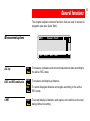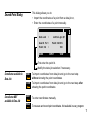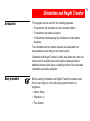
1
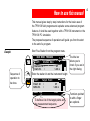
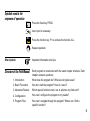
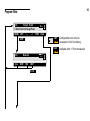
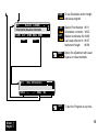
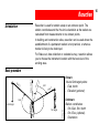
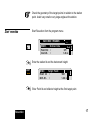
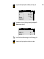
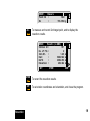
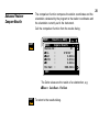
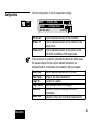
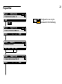
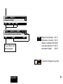
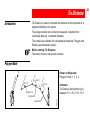
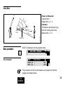
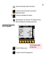
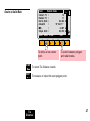
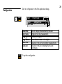
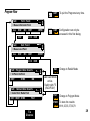
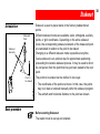
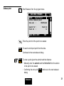
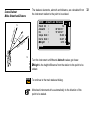
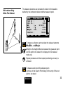
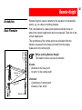
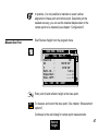
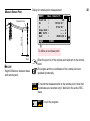
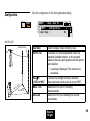
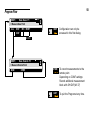
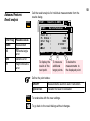
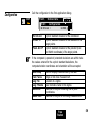
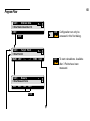
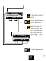
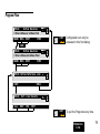
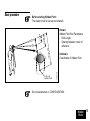
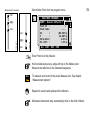
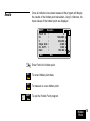
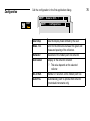
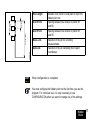
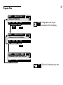
20
30
40
50
TPS1100 Professional Series
Application programs Field Manual 1
English
Version 1.0
The quick way to start with the TPS1100 Programs.
For additional details on single TPS1100 application program
functions refer to the Applications Reference Manual on the CD.
To use the equipment in the permitted manner, please refer to the
detailed safety instructions in the User Manual.
© 1998 Leica Geosystems AG Heerbrugg, ® All rights reserved.
2
Index
Orient. +
Height T.
Resection
Tie
Distance
Stakeout
How to use this manual
4
General functions
6
Orientation and Height Transfer
8
Resection
16
Tie Distance
24
Stakeout
30
Remote Height
46
Free Station
51
Reference Line
62
Hidden Point
72
Remote
Height
Free
Station
Reference
Line
Hidden
Point
3
How to use this manual
This manual gives step by step instructions for the basic uses of
the TPS1100 field programs and explains some advanced program
features. It shall be used together with a TPS1100 instrument or the
TPS1100 PC simulation.
The proposed sequence of operations will guide you from the start
to the end of a program.
Example
The title bar
allows you to
check if you are in
the right dialog.
Enter the station Id and the instrument height.
CONT
F1
FreST\
Point Id
Refl.Ht.
Target Point
:
ST
:
1.60 m
SEARC LIST
MC
Sequence of
operation to
be done.
MAIN MENU: PROGRAMS
FreST\
Station Data
Station Id :
ST
Inst.Ht. :
1.65 m
MC
PROG
MC
Start Free Station from the program menu.
VIEW
To define a list of the target points and
the measurement sequence.
Functions pointed
to with a finger
are optional.
4
Symbols used in the
sequence of operation
PROG
Press the fixed key PROG.
User input is necessary.
ALL
F1
Press the function key F1 to activate the function ALL.
Repeat operation.
Other Symbols
Important information and tips.
Structure of the Field Manual
Each program is constructed with the same chapter structure. Each
chapter answers questions:
1. Introduction
What does the program do? What are its typical uses?
2. Basic Procedure
How do I start the program? How do I use it?
3. Advanced Feature
Which special functions can I use to optimize my field work?
4. Configuration
How can I configure the program to my needs?
5. Program Flow
How can I navigate through the program? Where can I find a
specific function?
5
General functions
Measurement options
AREA\
ALL
ALL key
DIST and REC combination
ALL
F1
DIST
F2
REC
F3
CONT
CONT
F4
Measure Point
DIST
REC
MC
This chapter explains common functions that are used in almost all
programs (see also Quick Start).
CONT
To measure a distance and record measurement data according to
the active REC-mask.
To measure and display a distance.
To record displayed distance and angles according to the active
REC-mask.
To accept displayed distance and angles, and continue to the next
dialog without recording.
6
Search Point Dialog
This dialog allows you to:
• Import the coordinates of a point from a data job or,
MC
• Enter the coordinates of a point manually.
Data Job
:
control.gsi
Search for :
Point Id :
Point Id+E+N
100
SEARC
INPUT
VIEW
First enter the point Id.
Modify the data job selection if necessary.
Coordinates available in
Data Job
SEARC
To import coordinates from data job and go to the next step
without showing the point coordinates
VIEW
To import coordinates from data job and go to the next step after
showing the point coordinates
F1
F2
Coordinates NOT
available in Data Job
INPUT
F3
MEAS
F2
To enter coordinates manually.
To measure and record point coordinates. Not available in every program.
7
Orientation and Height Transfer
Introduction
This program can be used for the following purposes:
• To determine the orientation at the instrument station.
• To determine the station elevation.
• To determine simultaneously the orientation and the station
elevation.
The orientation and the station elevation are calculated from
measurements to as many as ten known points.
Orientation and Height Transfer is often used when more than one
known point is available around the station. Measurements to
additional known points allow a reliability control of the calculated
orientation and station elevation.
Basic procedure
Before starting Orientation and Height Transfer the station must
first be set using one of the following system functions or
programs:
• Station Setup
• Resection, or
• Free Station.
8
=0
t1
Hz1
Hz2
1st target
(E, N)
Dist 2
∆Elev.
2nd target
(E, N, H)
1100pr02
Hz
Orientation
Dis
1. Orientation only
Known:
Target points coordinates:
- East, North
Unknown:
- Orientation
Measure at least...
- Directions to 1 target point
2. Orientation and Height
Transfer
Known:
Target points coordinates:
- East, North, Elevation
Unknown:
- Orientation, Station Elevation
Measure at least...
- Distance and directions to 1
target point
Points with elevation only can be used for the determination of the
station elevation.
Orient. +
Height T.
9
Start Orientation from the program menu.
ORI\
Target Point
Point Id :
Refl.Ht. :
SEARC LIST
10
MC
MAIN MENU: PROGRAMS
1001
1.60 m
MC
PROG
VIEW
To define a list of the target points and
the measurement sequence.
Enter Point Id and reflector height at the first target point.
F1
ALL
F1
To search and import point coordinates from data job.
ORI\
Point Id
Hz
Measure
:
:
1001
363.5754 g
MC
SEARC
To measure and record first target point. See chapter
"Measurement options".
Repeat sequence "Target point entry and Measurement" for your
next target points.
Motorized instruments will drive automatically to the target point.
CALC
F6
To calculate the orientation and the station elevation.
The results dialog displays:
Results
Ori\
Results (L.SQRS)
Station Id :
ST1
No. of Pts :
3
Inst.Ht. :
1.65 m
East
:
5003.542 m
North
:
2356.703 m
Elevation :
453.344 m
S.ORI S.HT STORE MEAS
STORE
F3
+ CONT
F1
To set orientation only.
S.HT
F2
+ CONT
F1
To set station elevation only.
S.ORI
BOTH
F1
+
F2
MEAS
F4
Orient. +
Height T.
MORE
To record the Orientation and Height Transfer results.
S.ORI
F1
MC
• the current station coordinates.
• the oriented horizontal direction
• the a-posteriori standard deviations of the orientation and of the
station elevation.
To set both orientation and station elevation.
To measure additional target points.
Returns to the Target Point dialog.
11
Advanced feature:
Result analysis
Call the result analysis for individual measurements from the
results dialog.
F5
Error Flag
Possible values
NONE
HZ
Measurement
OK
Horizontal angle
DIST
error
Distance error
HT
More Information
Point Id
Pt. Status
Error flag
∆Hz
∆Dist
RECLC
Height difference
error
Results (L.SQRS)
MC
Ori\
:
:
:
:
:
<--
To display the
results of the
next point.
MC
Ori\
MORE
3
ON
NONE
0°00'03''
0.044 m
-->
MEAS
DEL
To measure
additional
target points.
To delete the
measurements to
the displayed point.
Define the point status:
RECLC
F1
ESC
ON/OFF
Measurements used/not used in calculation.
Ignore Elev.
Elevation not used in calculation.
To recalculate with the new settings.
To go back to the result dialogs without changes.
12
Configuration
CONF
F2
Target Point
Ori\
Configuration
Hz Ori Acc :
0.0100 g
Hz Ori Acc
Ht Acc TP
Posn AccTP
MC
Ori\
SHIFT
MC
Call the configuration in the first application dialog.
A priori standard deviation of the orientation.
A priori standard deviation of the elevation of the
target points.
A priori standard deviation of the position (East
and North coordinates) of the target points.
If the computed (a posteriori) standard deviations are within twice
the values entered for the a priori standard deviations, the
computed station coordinates and orientation will be accepted.
User Disp
Two Faces
Log File
Log FlName
Data Job
Meas. Job
Orient. +
Height T.
Use the display mask defined by the user.
Single or two face measurement.
Creation of a logfile.
User definable name for the logfile.
Selection of the job containing the fix point
coordinates.
Selection of the job for recording measurements.
13
Program Flow
14
SEARC LIST
<--
-->
MC
Ori\
Target Point
> Enter Point Id of Target Point
VIEW
CALC
SHIFT CONF
CONF
F2
CALC
F6
ALL
Measure
DIST
REC
MC
Ori\
CONT
I<>II
Configuration can only be
accessed in this first dialog.
available after 1 Point measured
STORE
To set Orientation and/or Height
and leave program
S.ORI
Station Point Number WI 11
Orientation correction WI 25
Station coordinates WI 84-86
Last used reflector Ht WI 87
Instrument Height
WI 88
F3
S.ORI S.HT STORE MEAS
ROBST
MC
Ori\
Results (L.SQRS)
> East, North, Elevation, Orientation
F1
MORE
S.HT
F2
PLOT
Ori\
More Information
RECLC
<--
-->
MEAS
ROBST
F2
Option for adjustment with Least
Square or robust methods.
QUIT
To quit the Program at any time.
MC
SHIFT
DEL
SHIFT
F6
Orient. +
Height T.
15
Resection
Introduction
Resection is used for station setup on an unknown point. The
station coordinates and the Hz-circle orientation at the station are
calculated from measurements to two known points.
In building and construction sites, resection can be used where the
establishment of a permanent station is not practical, or where a
marker is likely to be destroyed.
For Stake out, data collection or cadastral survey, resection allows
you to choose the instrument location with the best view of the
working area.
Known:
1st and 2nd target points:
- East, North
- Elevation (optional)
=0
t2
Hz
Dis
Orientation
Basic procedure
Hz1
Dis
t1
Hz2
1st target
1100pr03
2nd target
Unknown:
Station coordinates:
- Stn. East, Stn. North
- Stn. Elev. (optional).
Orientation
16
Check the geometry of the target points in relation to the station
point. Avoid very small or very large angles at the station.
Start resection
Start Resection from the program menu.
Station Data
:
:
ST1
1.65 m
MC
RESEC\
Point Id
Inst.Ht.
MC
MAIN MENU: PROGRAMS
PROG
CONT
F1
RESEC\
Point Id
Refl.Ht.
Target Point
:
:
1001
1.60 m
MC
Enter the station Id and the instrument height.
Enter Point Id and reflector height at the first target point.
Resection
17
SEARC
To search and import point coordinates form data job.
RESEC\
Measure
Point Id :
Hz
:
V
:
Refl.Ht. :
Slope Dist :
F1
g
g
m
m
To measure and record first target point. (see chapter for
"Measurement options")
RESEC\
Point Id
Refl.Ht.
Target Point
:
:
MC
ALL
1001
363.5754
99.5647
1.60
-----
MC
F1
1002
1.60 m
Enter Point Id and reflector height at the 2nd target point.
SEARC
F1
To search and import point coordinates from data.
18
F1
1002
175.5768 g
To measure and record 2nd target point, and to display the
resection results.
RESEC\
Results (L.SQRS)
Station Id :
ST1
No. of Pts :
2
Inst.Ht. :
1.65 m
East
:
5003.542 m
North
:
2356.703 m
Elevation :
453.344 m
SET
STORE
F3
SET
F1
Resection
STORE
MC
ALL
Measure
:
:
MC
RESEC\
Point Id
Hz
COMP
To record the resection results.
To set station coordinates and orientation, and close the program.
19
Advanced Feature:
Compare Results
The comparison function compares the station coordinates and the
orientation calculated by the program to the station coordinates and
the orientation currently set in the instrument.
Call the comparison function from the results dialog.
F5
MC
Results (L.SQRS)
RESEC\
Compare Results
Station Id :
ST
∆Ori.
:
0°00'03''
∆East
:
0.002
∆North
:
0.012
∆Ht
:
0.034
Fix East :
5003.542
MC
RESEC\
COMP
m
m
m
m
CONT
The Delta values are the results of a substraction, e.g.
∆ East = Calc.East - Fix East
CONT
F1
To return to the results dialog.
20
Configuration
CONF
F2
RESEC\
Station Data
RESEC\
Configuration
Hz Ori Acc :
0.0100 g
MC
SHIFT
MC
Call the configuration in the first application dialog.
Hz Ori Acc
Ht Acc TP
A priori standard deviation of the orientation.
A priori standard deviation of the elevation of the
target points.
Posn AccTP
A priori standard deviation of the position (East
and North coordinates) of the target points.
If the computed (a posteriori) standard deviations are within twice
the values entered for the a priori standard deviations, the
computed station coordinates and orientation will be accepted.
User Disp
Two Faces
Log File
Log FlName
Data Job
Meas. Job
Resection
Use the display mask defined by the user.
Single or two face measurement.
Creation of a logfile.
User definable name for the logfile.
Selection of the job containing the fix point
coordinates.
Selection of the job for recording measurements.
21
Program Flow
22
MC
Resec\
Station Data
> Enter Point Id and Inst. Ht.
SHIFT CONF
CONT
F2
Resec\
Target Point
> Enter 1st Point Id and Refl. Ht.
<--
-->
VIEW
ALL
DIST
REC
MC
Resec\
Measure
> Measure 1st Point
CONT
Resec\
Target Point
> Enter 2nd Point Id and Refl. Ht.
SEARC
<--
-->
VIEW
MC
SEARC
MC
CONF
Configuration can only be
accessed in this first dialog.
DIST
REC
CONT
Resec\
Results (L.SQRS)
> East, North, Elevation; Orientation
SET
STORE
MC
ALL
MC
Resec\
Measure
> Measure 2st Point
COMP
STORE
F3
To set Station and
leave program.
SHIFT QUIT
F6
Resection
Station Point Number WI 11
Orientation correction WI 25
Station coordinates WI 84-86
Last used reflector Ht WI 87
Instrument Height
WI 88
To quit the Program at any time.
23
Tie Distance
Introduction
Tie Distance is used to calculate the distance and the azimuth of a
segment defined by two points.
The polygon points can be directly measured, imported from
coordinate data job, or entered manually.
Two modes are available for calculating tie distances: Polygon and
Radial (see illustrations below).
Before starting Tie Distance:
The station must be set up and oriented.
Polygon Mode
N
Az 1-2
Az 2-3
2
1
3
Az 3-4
Tie Dist 1-2
Tie Dist 2-3
Tie Dist 3-4
4
1100pr04
Hz
=0
°0
0'0
0''
Known or Measured:
Polygon Points 1, 2, 3, 4
Unknown:
Tie Distance and Azimuth (Az.)
between Pt.1 - Pt.2, Pt.2 - Pt.3
...
24
Radial Mode
''
N
1-
2
3
2
4
Tie Dist 1-3
Center
Point
Tie D
ist
Tie Dist 1-2
Basic procedure
3
1-4
4
Start Tie Distance from the program menu.
MAIN MENU: PROGRAMS
PROG
First two points
TieD\
First Point
Point Id :
Refl. Ht. :
MC
Hz
1
1-
Known or Measured:
Central Point: 1
Radial Point: 2, 3, 4
Unknown:
Tie Distance and Azimuth (Az.)
from the central point to the
radial points 2, 3, 4.
100
1.65 m
MC
=0
°00
Az
Az
1-
1100pr05
'00
Az
The procedure for the first tie distance is the same for both the
polygon and radial modes.
Tie
Distance
25
Enter point Id and reflector height of the first point.
ALL
F1
Or IMPOR
F6
To measure and record the first point. (see chapter for
"Measurement options")
To import point coordinates from a data file.
TieD\
Polygon Mode
1st Point :
10
2nd Point :
11
Horiz.Dist :
25.453 m
Azimuth
:
15°34'21''
∆Ht.
:
0.987 m
Slope Dist :
25.472 m
Results in Polygon Mode
NEXT
F1
STORE
F3
NEXT
F1
STORE
F2
F3
To record Tie Distance results.
MC
Repeat sequence for the second point. This completes the first tie
distance and displays the corresponding results dialog.
RAD
F4
F5
F6
To switch between polygon
and radial modes.
To measure or import the next polygon point.
26
NEXT RESET STORE
F1
F2
F3
To define a new center
point.
STORE
F3
NEXT
F1
MC
TieD\
Radial Mode
Center Pt :
10
Radial Pt :
11
Horiz.Dist :
25.453 m
Azimuth
:
15°34'21''
∆Ht.
:
0.987 m
Slope Dist :
25.472 m
Results in Radial Mode
POLY
F4
F5
F6
To switch between polygon
and radial modes.
To record Tie Distance results.
To measure or import the next polygon point.
Tie
Distance
27
Configuration
Call the configuration in the first application dialog.
F2
TieD\
First Point
TieD\
Configuration
Two Faces :
User Disp
Two Faces
Log File
Log FlName
Meas. Job
Data Job
CONT
F1
MC
CONF
NO
MC
SHIFT
Use the display mask defined by the user.
Single or two face measurement.
Creation of a logfile.
User definable name for the logfile.
Selection of the job for recording measurements.
Selection of the job containing the fix point
coordinates.
To quit the configuration.
28
Program Flow
SHIFT
QUIT
To quit the Program at any time.
CONF
Configuration can only be
accessed in this first dialog.
F6
ALL
DIST
REC
CONF
MC
TieD\
First Point
> Measure first/center Point
CONT
DIST
SHIFT
F2
I<>II VIEW
REC
MC
Tied\
Next Point
> Measure next Point
ALL
IMPOR
CONT
IMPORT
TieD\ Polygon Mode Results
> 1st Point / 2nd Point
STORE
RAD
TieD\ Radial Mode Results
> Center Point / Radial Point
NEXT RESET STORE
POLY
MC
NEXT
MC
I<>II VIEW
RAD
F5
Last used Mode
active.
Switch with F5
(RAD/POLY)
POLY
Change to Polygon Mode
STORE
To store the results:
WI11,25,35,37,39,79
F5
F3
Tie
Distance
Change to Radial Mode
29
Stakeout
Introduction
Stakeout is used to place marks in the field at predetermined
points.
Different stakeout modes are available: polar, orthogonal, auxiliary
points, or grid coordinates. Depending on the active stakeout
mode, the corresponding stakeout elements of the measured point
are calculated in relation to the point to be staked.
Changing to a different stakeout mode is possible at anytime.
Measured
Point
Stakeout
elements
Coarse stakeout is an optional step for approximate positioning
preceeding the iterative stakeout process. It may be used to direct
the rod person from the point that has just been staked to the next
point.
The points to be staked can be defined in two ways:
1100pr06
Point to
be staked
Basic procedure
• The coordinates of the point are known. In this case, the points
may be in data or entered manually within the stakeout program.
• The azimuth and horizontal distance to the point are known.
Before starting Stakeout:
The station must be set up and oriented.
30
PROG
Start Stakeout from the program menu.
MC
MAIN MENU: PROGRAMS
STAKE\
Search Point
Define Stakeout point
Data Job :
POINTS.GSI
Search for :
Point Id :
MC
Stakeout point
Point Id
12
SEARC MSTAK INPUT
VIEW
Enter the point Id of the point to be staked.
SEARC
F1
To search and import point from the data.
Continues to the next stakeout dialog.
MSTAK
F2
To enter a point given the azimuth and the distance:
• Manually enter the azimuth and the Horiz.Dist from the station
to the point to be staked.
• Confirming the entry with STAKE
F1 continues to the next stakeout
dialog.
Stakeout
31
STAKE\ Azimuth and Distance
Point Id :
12
Azimuth
:
30°03'23''
Hz
:
15°43'02''
Slope Dist :
35.60 m
Horiz Dist :
34.97 m
∆Height
:
0.75 m
Az
Hz
p
Slo
im
uth
is
eD
tan
ce
STAKE
12
1100pr07
Hz
=0
°00
'00
"
N
MC
The stakeout elements, azimuth and distance, are calculated from
the instrument station to the point to be staked.
Coarse Stakeout
Mode: Azimuth and Distance
STAKE
F1
Turn the instrument until Hz and Azimuth values get closer.
∆ Height is the height difference from the station to the point to be
staked.
To continue to the main stakeout dialog.
Motorized instruments drive automatically to the direction of the
point to be staked.
32
∆D
is
t-
STAKE\
Point Id
Refl. Ht.
∆Hz
∆Dist
∆Height
Elevation
ALL
DIST
REC
CONT
m
m
m
m
POSIT
z+
DIST To measure a distance and calculate the stakeout elements
12
1100pr08
∆H
Polar Stake Out
:
12
:
1.65
:
16°03'23''
:
-1.23
:FILL
0.15
:
159.90
MC
The stakeout elements are calculated in relation to the baseline
defined by the instrument station and the measured point.
Main stakeout dialog
Mode: Polar Stakeout
F2
∆ Hz, ∆ Dist, and ∆ Height.
∆Height is the height difference between the measured point
and the point to be staked. It is displayed in 3D stakeout
mode only.
Repeat procedure unti thel required positioning accuracy is
achieved.
ALL
F1
To measure and record the stakeout point.
Continues to the Search Point dialog for the entry of the next
point to be staked.
Stakeout
33
Advanced Feature:
Configuration of the
stakeout method
F2
Coarse Mode
MC
STAKE\ Azimuth & Distance
STAKE\
Method
Coarse Mod :
Azimuth & Dist
SHIFT METHD
MC
Call the dialog for the configuration of the stakeout method from
any stakeout dialog.
• OFF
Selection of the coarse stakeout mode (see
chapter "Advanced Feature: Coarse mode").
Selection of the main stakeout mode. (see
chapter "Advanced Feature:: Stakeout mode").
Selection of the mode for automatic positioning
to the point to be staked (for motorized
instruments only).
No automatic positioning.
• 2D or 3D
2-dimensional or 3-dimensional positioning.
Ht Offset
Height offset addet to the design elevations of
the points to be staked. CUT and FILL values
refer to the elevations modified by the offset.
Select the graphic mode to be displayed in the
main stakeout dialog (see chapter "Advanced
Feature: Graphic mode").
Stake Mode
Auto Pos.
Graphics
34
Symbols
• From Sta. (▲▼)
• To Sta. (▼▲)
Select the display mode of symbols in the
stakeout dialog. The symbols may be used to
guide the rod person to the point to be staked.
Guidance of the rod person from the instrument
station.
Guidance at the rod, in relation to the
instrument station (e.g. if working in RCS
mode).
Advanced Feature:
Coarse Mode
Coarse Mode = None
The coarse mode is switched off. After the entry of the point to be
staked in the Search Point dialog, the main stakout dialog will be
accessed directly.
Stakeout
35
11
Lin
e+
Of f s
STAKE\
Point Id
Azimuth
Hz
Line
Offset
∆Height
et+
12
Line Offset
:
12
:
30°03'23''
:
15°43'02''
:
1.550 m
:
1.430 m
:
0.982 m
MC
The stakeout elements are calculated in relation to the baseline
defined by the two last points staked out.
Coarse Mode = Line Offset
STAKE
Line and Offset values are displayed after two points have
been staked out.
∆ Height is the height difference from the last point staked.
1100pr09
10
STAKE To continue to the main stakeout dialog.
F1
Motorized instruments drive automatically to the direction of
the point to be staked.
36
–
gth
en
11
STAKE\
Point Id
Azimuth
Hz
∆Length
∆Cross
∆Height
STAKE
∆L
oss+
12
∆ Length and ∆ Cross values are displayed after the first
point have been staked out.
1100pr10
∆C r
Orthogonal
:
12
:
30°03'23''
:
15°43'02''
:
-1.550 m
:
1.430 m
:
0.982 m
MC
The stakeout elements are calculated in relation to the baseline
defined by the instrument station and the last point staked out.
Coarse Mode = Orthogonal
STAKE
F1
∆ Height is the height difference from the last point staked.
To continue to the main stakeout dialog.
Motorized instruments drive automatically to the direction of the
point to be staked.
Stakeout
37
Advanced Feature:
Main stakeout mode
38
en
gth
–
STAKE\
Point Id
Refl. Ht.
∆Cross
∆Length
∆Height
Elevation
ALL
∆L
oss+
DIST
REC
CONT
12
1.65
1.430
-1.550
0.982
0.750
m
m
m
m
m
POSIT
DIST To measure a distance and calculate the stakeout elements
12
F1
∆ Cross and ∆ Length.
∆Height is the height difference between the measured point
and the point to be staked. It is displayed in 3D stakeout
mode only.
Repeat procedure until required positioning accuracy is
achieved.
1100pr11
∆C r
Orthogonal
:
:
:
:
:FILL
:
MC
The stakeout elements are calculated in relation to the baseline
defined by the instrument station and the measured point.
Stake Mode = Orthogonal Stake
ALL
F1
To measure and record stakeout point.
Continues to the Search Point dialog for the entry of to the
next point to be staked.
STAKE\
Auxiliary points
Point Id :
12
Refl. Ht. :
1.65 m
Hz angle 1 :*
----- m
Dist. 1
:*
----- m
Hz angle 2 :
----- m
Dist. 2
:
----- m
Hz angle 1
Dis
t.1
ALL
DIST
REC
CONT
MC
In this mode, the stakeout elements for points that can not be
sighted directly are caculated from measurements to two auxiliary
points.
Stake Mode = Auxiliary Point
POSIT
12
Di
st
.2
The auxiliary point to be measured is marked with an
asterisk (*).
DIST To measure a distance to the first auxiliary point and
1100pr12
Hz angle 2
F2
calculate the stakeout elements Hz angle 1 and Dist. 1.
The asterisks switches to the second auxiliary point to be
measured.
DIST To measure a distance to the second auxiliary point and
F2
calculate the stakeout elements Hz angle 2 and Dist. 2.
CONT To stake out the next point. Continues to the dialog for the
F4
entry of the stakeout point.
Stakeout
39
STAKE\
Point Id
Refl. Ht.
∆East
∆North
∆Height
Elevation
North
DIST
REC
CONT
m
m
m
m
m
POSIT
∆N
or
th
–
ALL
Grid Coordinates
:
12
:
1.65
:
1.430
:
-1.550
:FILL
0.982
:
0.750
MC
The displacements along the grid coordinates axes are calculated
from the measured point to the point to be staked.
Stake Mode = Grid Coordinates
East
12
DIST To measure a distance and calculate the stakeout elements
F2
1100pr13
∆East+
∆ East, ∆ North and ∆ Height.
∆Height is the height difference between the measured point
and the point to be staked. It is displayed in 3D stakeout
mode only.
Repeat the procedure until the required positioning accuracy
is achieved.
ALL
F1
To measure and record the stakeout point.
Continues to the Search Point dialog for the entry of to the
next point to be staked.
40
Advanced Feature:
Graphic mode
The following modes are available for displaying stakeout graphics
in the stakeout dialog:
OFF
No graphics are displayed.
From Station
The graphics are oriented from the instrument
station to the point to be staked. This mode is
recommended for guiding the rod person from
the station.
The graphics are oriented from the current
reflector position to the station. This mode is
recommended for stakeout in RCS mode.
The graphics are oriented to the North. This
mode is recommended for stakeout in RCS
mode and in the grid coordinates mode.
The graphics are oriented to the South. This
mode is recommended for stakeout in RCS
mode and in the grid coordinates mode.
To Station
To North
From North
Stakeout
41
Illustration of the stakeout dialog in the polar stake mode after
having measured a distance.
STAKE\
Polar Stakeout
12
0.000 m
16°03'23''
-1.230 m
0.150 m
159.900 m
hr :
∆Hz :
∆D :
FILL :
Elev :
ALL
DIST
REC
CONT
MC
Graphic mode= from Station
Stake mode = Polar Stake
5
*
POSIT
Symbols:
Instrument station
Reflector position
Point to be staked
*
The scale gives an indication of the distance between the
reflector position and the point to be staked.
The graphics is updated dynamically when turning the instrument
towards the point to be staked.
42
Configuration
CONF
STAKE\
Search Point
STAKE\
Configuration
3D Stake :
F2
3D Stake
3-dimensional stakeout
☞ The height elements are displayed only if an
elevation is available for the point to be staked.
Log File
Creation of a logfile.
Log FlName
User definable name for the logfile.
Data Job
Selection of the job containing the fix point
coordinates.
Selection of the job for recording measurements.
Meas. Job
CONT
F1
ON
MC
SHIFT
MC
Call the configuration in the first application dialog:
To exit the configuration dialog.
Stakeout
43
44
Program Flow
SHIFT QUIT
F6
SEARC MSTAK INPUT
To quit the Program at any time.
MC
Stake\
Search Point
> Enter Point Id
SHIFT
VIEW
CONF
F2
CONF
MC
Stake\
Manual Entry
> Enter Azimuth, Horiz. Dist.
Configuration can only be
accessed in this first dialog.
STAKE
METHD
PLOT
Stake\
Select Method
Select:
Coarse Mode:
none/line/ortho/azi&dist
Stake mode:
Polar/Ortho/Aux/Grid
Auto Pos:
OFF/2D/3D
Ht. Offset:
[m]
Graphics:
no/to stat/from stat/to north
Symbols:
From Sta./To Sta.
CONT
MC
Stake\
Coarse Mode
> Display depends on mode
MC
STAKE
DIST
METHD
REC
CONT
POSIT
PLOT I<>II
Stake\
Select Method
Select:
Coarse Mode:
none/line/ortho/azi&dist
Stake mode:
Polar/Ortho/Aux/Grid
Auto Pos:
OFF/2D/3D
Ht. Offset:
[m]
Graphics:
no/to stat/from stat/to north
Symbols:
From Sta./To Sta.
MC
ALL
MC
Stake\
Stake Mode
> Display depends on mode
CONT
POLAR ORTHO
F1
SHIFT QUIT
F6
Stakeout
F2
F3
AUX
F4
GRID
F5
F6
To quit the Program at any time.
45
Remote Height
Introduction
Remote Height is used to determine the elevation of inaccessible
points, e.g. on cables or building facades.
Basic Procedure
First, the distance to a base point situated vertically below (or
above) the remote height point must be measured. Then aim to the
remote height point.
Vertical
alignement
The coordinates of the remote point are calculated from the
distance measured to the base point and from the angles
measured to the remote point.
Remote
Point
1100pr14
ist.
Slope D
Base Point
Before starting Remote Height:
The station must be set up and oriented.
Known:
- Distance to the base point
- Hz and V to the remote point
Unknown:
- Coordinates of remote point:
Elevation, East, North
46
In practice, it is not possible to maintain an exact vertical
alignement of base point and remote point. Depending on the
needed accuracy, you can set the maximal displacement of the
remote point to be tolerated (see chapter "Configuration").
MAIN MENU: PROGRAMS
REMHT\
Meas. Base Pt.
Point Id :
102
Hz
:
123°32'23''
V
:
10°34'20''
Refl. Ht. :
1.60 m
Slope Dist :
----- m
Elev. Diff :
----- m
ALL
DIST
MC
PROG
MC
Start Remote Height from the program menu.
Measure Base Point
REC REMOT
Enter point Id and reflector height at the base point.
ALL
F2
To measure and record the base point. (See chapter "Measurement
options").
Continues to the next dialog for remote point measurements.
Remote
Height
47
48
REMHT\
Meas. Remote Pt.
Point Id :
103
Hz
:
123°32'23''
V
:
10°34'20''
Slope Dist :
----- m
∆Ht. Diff. :
----- m
East
:
45300.654 m
∆Ht. Diff
Remote Point
BASE
MC
Dialog for remote point measurement.
Measure Remote Point
STORE
1100pr15
To define a new base point.
Base
Point
Enter the point Id of the remote point and aim to the remote
point.
∆ Ht.Diff:
Height Difference between base
and remote point.
The angles and the coordinates of the remote point are
updated dynamically.
STORE To record the measurements to the remote point. Note that
F3
SHIFT
coordinates are recorded only if defined in the active RECmask.
QUIT
F6
To quit the program.
Configuration
Call the configuration in the first application dialog:
F2
REMHT\
Meas. Base Pt.
REMHT\
Configuration
User Disp :
MC
CONF
NO
MC
SHIFT
Hz.Pos.Tol:
1100pr16
Remote Point
Ho
riz.
Dis
t
User Disp
Use the display mask defined by user.
Hz.Pos.Tol
Tolerance for vertical alignement: enter the
maximal horizontal distance to be tolerated
between the base point position and the remote
point position.
☞ A warning is displayed if the tolerance is
exceeded.
Rec ∆Ht
= REC in WI37
To store the ∆Height Difference between
base point and remote point as record WI37.
Meas. Job
Selection of the job for recording
measurements.
Data Job
Selection of the job containing the fix point
coordinates.
Hz.Pos.Tol
Remote
Height
49
Program Flow
REMHT\
Meas Base Pt
> Measure Base Point
ALL
DIST
MC
50
REC REMOT
SHIFT
CONF
Configuration can only be
accessed in this first dialog.
STORE
To record measurements to the
remote point.
Depending on CONF-settings:
Record additional measurement
block with ∆Ht Diff (WI 37)
QUIT
To quit the Program at any time.
F2
CONF
REMHT\
Meas Remote Pt
> Measure Remote Point
BASE
MC
I<>II
STORE
F3
SHIFT
F6
Free Station
Introduction
Free station is used for a station setup on an unknown point.
The station coordinates and the Hz-circle orientation at the station
are calculated from measurements for up to ten known points.
A combination of directions and distances or of directions only may
be measured to the target points.
If bad target points are found in the Free Station results, they can
be suppressed or remeasured. The Free Station can be
immediately recalculated.
Free Station is mostly used when more than two known points are
available around the station. Measurements to additional known
points allow a reliability control of the calculated station coordinates
and orientation.
In building and construction sites, Free Station can be used where
the establishment of a permanent station is not practical, or where
a marker is likely to be destroyed.
For Stake out, data collection or cadastral survey, Free Station
allows you to choose the instrument location with the best view of
the working area.
Free
Station
51
=0
52
Hz
Orientation
Basic procedure
Di
Hz1
st
1
1st target
Hz2
Dist 2
Hz3
Dist
2nd target
3
1100pr17
Station
3rd target
Known:
Target point coordinates:
- East, North
- Elevation (optional)
Unknown:
Station coordinates:
- Stn. East, Stn. North
- Stn. Elev. (optional).
Orientation
Measure at least...
Distance and directions to 2
target points
or directions only to 3 target
points
Points with elevation only can be used in Free Station.
Start Free Station from the program menu.
MAIN MENU: PROGRAMS
FreST\
Station data
Station Id :
Inst.Ht. :
MC
PROG
1001
1.65 m
CONT
F1
FreSt\
Point Id
Refl.Ht.
Target Point
:
:
SEARC LIST
1001
1.60 m
MC
Enter the station Id and the instrument height.
VIEW
To define a list of the target points
and the measurement sequence.
Enter Point Id and reflector height at the first target point.
SEARC
F1
To search and import point coordinates from data job.
Free
Station
53
ALL
ALL
F1
DIST
REC
1001
363.5754
99.5647
1.60
-----
MC
FreSt\
Measure
Point Id :
Hz
:
V
:
Refl.Ht. :
Slope Dist :
g
g
m
m
CONT
To measures and record first target point.
FreSt\
Point Id
Refl.Ht.
Target Point
:
:
1002
1.60 m
MC
See chapter "Measurement options".
Enter Point Id and reflector height at the 2nd target point.
SEARC
F1
To search and import point coordinates from data job.
54
ALL
Measure
:
:
1002
175.5768 g
MC
FreSt\
Point Id
Hz
To measure and record 2nd target point.
F1
Repeat sequence for the next target points.
Note: from the third point on, motorized instruments will drive
automatically to the target.
CALC
F6
To calculate the station coordinates and the orientation.
You may calculate after having measured at least:
• Distance and angles to 2 target points or
• Angles to 3 target points
Free
Station
55
56
The results dialog displays:
Free Station results
• the station coordinates
• the oriented direction (Hz. Ori)
• the a-posteriori standard deviations of the station coordinates
and orientation
FreSt\
Results (L.SQRS)
Station Id :
ST1
No. of Pts :
3
Inst.Ht. :
1.65 m
East
:
5003.542 m
North
:
2356.703 m
Elevation :
453.344 m
SET
STORE
F3
SET
F1
MEAS
F4
STORE MEAS
MORE
MC
• the local scale factor
COMP
To record the free station results.
To set station coordinates and orientation, and close the program.
To measure additional target points. Returns to the Target Point
dialog.
Advanced Feature:
Compare Results
The comparison function compares the station coordinates and the
orientation calculated by the program to the station coordinates and
the orientation currently set in the instrument.
Call the comparison function from the results dialog.
F5
MC
Results (L.SQRS)
FreSt\
Compare Results
Station Id :
ST
∆Ori.
:
0°00'03''
∆East
:
0.002
∆North
:
0.012
∆Ht
:
0.034
Fix East :
5003.542
MC
FreSt\
COMP
m
m
m
m
CONT
The Delta values are the results of a substraction, e.g.
∆ East = Calc.East - Fix East
CONT
F1
To return to the results dialog.
Free
Station
57
Call the result analysis for individual measurements from the
results dialog.
F5
Error Flag
Possible values
NONE
HZ
Measurement
OK
Horizontal angle
DIST
error
Distance error
HT
FreSt\
FreSt\
More Information
Point Id
Pt. Status
Error flag
∆Hz
∆Dist
RECLC
Height difference
error
Results (L.SQRS)
MC
MORE
:
:
:
:
:
<--
To display the
results of the
next point.
MC
Advanced Features:
Result analysis
3
ON
NONE
0°00'03''
0.044 m
-->
MEAS
DEL
To measure
additional
target points.
To delete the
measurements to
the displayed point.
Define the point status:
RECLC
F1
ESC
ON/OFF
Measurements used/not used in calculation.
Ignore Elev.
Elevation not used in calculation.
To recalculate with the new settings.
To go back to the result dialogs without changes.
58
Configuration
CONF
F2
FreSt\
Station Data
FreSt\
Configuration
Hz Ori Acc :
0.0100 g
Hz Ori Acc
Ht Acc TP
Posn AccTP
MC
SHIFT
MC
Call the configuration in the first application dialog.
A priori standard deviation of the orientation.
A priori standard deviation of the elevation of the
target points.
A priori standard deviation of the position (East
and North coordinates) of the target points.
If the computed (a posteriori) standard deviations are within twice
the values entered for the a priori standard deviations, the
computed station coordinates and orientation will be accepted.
User Disp
Two Faces
Log File
Log FlName
Data Job
Meas. Job
Use the display mask defined by the user.
Single or two face measurement.
Creation of a logfile.
User definable name for the logfile.
Selection of the job containing the fix point
coordinates.
Selection of the job for recording measurements.
Free
Station
59
Program Flow
60
MC
FreSt\
Station Data
> Enter Station Id and Inst. Ht.
CONT
SHIFT CONF
F2
CONF
SEARC LIST
<--
-->
MC
FreSt\
Target Point
> Enter Point Id
VIEW
CALC
CALC
F6
ALL
DIST
REC
MC
FreSt\
Measure
> Enter Measure Points
CONT
I<>II
Configuration can only be
accessed in this first dialog.
To start calculations. Available
after 3 Points have been
measured.
STORE MEAS
ROBST
MORE
PLOT
SET
To set the Station and leave the
program.
ROBST
Option for adjustment with Least
Square or robust methods.
STORE
Station Point Number WI 11
Orientation correction WI 25
Station coordinates WI 84-86
Last used reflector Ht WI 87
Instrument Height
WI 88
F1
COMP
SHIFT
F2
F3
FreSt\
More Information
> Results analysis+Additional measurem.
RECLC
<--
-->
MEAS
MC
SET
MC
FreSt\
Results (L.SQRS)
> East, North, Elevation; Orientation
DEL
SHIFT
QUIT
F6
To quit the Program at any time.
Free
Station
61
Reference Line
Introduction
This program is used to set out points along a reference line, with
various offset left and right of the line. The reference line can be
shifted with parallel offsets or even rotated to match predefined
setting out instructions.
The orthogonal setting out elements of the target points are
calculated in relation to the defined reference line.
In Building and Construction, Reference Line is the specialised
program to set out building foundations (batter staking).
It may also be used for simple alignement types such as water and
sewer line layout, or straight roadlines and bridges.
It is very convenient for orthogonal set out thanks to various offset
possibilities and because the point coordinates do not need to be
precalculated. Only the coordinates of the start and end points of
the reference line are needed.
62
Basic procedure
Before starting Reference Line:
The station must be set up and oriented.
A baseline shall be defined in the first step. It can be used as a
reference line or serve as a base for the definition of an offset or
rotated reference line. In the picture, the reference line is defined
by a parallel offset to the right of the baseline.
N
Known:
- 1st BasePt
- 2nd BasePt
Parallel Offset between
Reference line and Baseline.
f. L
ine
∆Offset
∆L
1100pr18
Ba
se
Re
lin
e
ine
2nd Base Pt.
1st Base Pt.
Unknown:
∆ Offset, ∆ Line:
Position of point to set out on
the reference line.
Offset
Line of sight to the baseline points is not needed. They can
be imported from a data file.
Reference
Line
63
Start Reference Line from the program menu.
Refere
line
Base
1100pr19
nce L
ine
Offset Offset +
1st Base Pt.
Offset +
Offset -
direction of the
baseline
to the right of the
baseline
to the left of the
baseline
MC
REFLN\
Define Baseline
1st Point of Baseline
2nd Base Pt.
64
MC
MAIN MENU: PROGRAMS
PROG
Enter the first point of the baseline.
SEARC To search and import point from data job.
F1
Repeat sequence for second point of baseline.
And define the reference line parameters:
REFLN\ Define Reference Line
1st BasePt :
1
2nd BasePt :
2
Offset
:
0.000 m
CONT
MC
Define Reference Line
NEW-L
To define new baseline.
Offset = 0
Reference line = Baseline
Offset ≠ 0
Reference line parallel to Baseline
RefLn\Reference Line Results
Point Id :
3
∆Offset
:
1.230 m
∆Line
:
2.463 m
∆Ht
:
0.235 m
Elevation :
100.500 m
Lin
e
F1
MC
CONT
Setting Out elements
DIST
REC
CONT
Re
fer
en
ce
ALL
Enter Point Id to be set out.
∆Offse
t+
DIST To measure a distance and trigger the calculation of the
F2
1st Ref. Point
1100pr20
∆L
ine
+
Measured
Point
setting out elements: ∆Offset, ∆Line and ∆Ht.
∆Ht:
Elevation:
∆ Offset
∆Offset+
∆ Line
∆Line+
Perpendicular offset
To the right of the
reference line.
Line offset from the
1st Ref. Point.
In the line direction.
ALL
F1
SHIFT
Height Offset in relation to the reference
Elevation (Elevation of the 1st Base Point).
Elevation of the measured point.
To measure and record setting out point. Returns to the
dialog for the definition of the reference line.
QUIT
F6
To quit the Reference Line program.
Reference
Line
65
Advanced Feature:
Rotated Ref. Line
REFLN\ Define Reference Line
1st BasePt :
1
2nd BasePt :
2
Offset
:
5.000 m
Line
:
1.500 m
:
15°00'00''
Angle α
CONT
f. L
ine
Baseline
Configuration:
Line / α = ON
2nd Base Pt.
NEW-L
Enter the Line offset to define the starting point of the
reference line (1st Ref. Point).
Re
∆Offse
MC
Dialog for the definition of a rotated Reference line:
t+
Enter the rotation angle α .
∆L
ine
CONT
F1
Offset +
1st Base Pt.
1100pr21
Line +
1st Ref.
Point
REFLN\
Point Id
∆Offset
∆Line
∆Ht
Elevation
ALL
Ref Line Results
:
3
:
1.230
:
2.463
:
0.235
:
100.500
DIST
REC
MC
+
α
m
m
m
m
CONT
DIST To measure a distance and trigger the calculation of the
F2
setting out elements in relation to the new reference line and
it's starting point.
66
For the configuration Ref.Elev. = 1st Base Point, the reference
elevation for the calculation of ∆Height values is the elevation of
the 1st base point.
You can modify the reference elevation by specifiying a height offset
(Ht.Offset) in the dialog for the definition of the reference line.
REFLN\ Define Reference Line
1st BasePt :
1
2nd BasePt :
2
Offset
:
0.000 m
Line
:
0.000 m
:
0°00'00''
Angle α
Ht.Offset :
1.500 m
MC
Advanced Feature:
Constant reference
elevation
Ht Offset+
Ref. Elevation
1st Base Pt.
Setting out element:
∆Ht
along the vertical, in
relation to the
Reference elevation
∆Ht+
∆Ht–
1100pr22
Elevation
Configuration:
Ref. Elev. = 1st Base Point
Ht. Offset = ON
Reference
Line
67
For the configuration Ref.Elev. = Baseline, the reference elevation
for the calculation of ∆Ht values is the elevation of the baseline at
the reflector position.
You can modify the reference elevation by specifiying a height offset
(Ht.Offset) in the dialog for the definition of the reference line.
Configuration:
Ref. Elev. = Reference Line
Ht. Offset = ON
Elevation
∆ Perp.Ht
∆Ht+
n
Ref. Elevatio
∆Spat.Dist+
2nd Base Point
1100pr23
Ht Offset+
1st Base Point
Setting out elements:
∆Ht
Along vertical
∆Perp.Dist Perpendicular to
the Ref. line
∆Spat.Dist
Line offset along
the Ref. line
Results dialog with setting out elements:
REFLN\
Ref Line Results
Point Id :
3
∆Offset
:
1.230
∆Line
:
2.463
∆Ht
:
0.235
∆Perp.Dist :
100.500
∆Spat.Dist :
ALL
DIST
REC
CONT
MC
Advanced: Height Offset
Interpolated reference
elevation
m
m
m
m
68
Configuration
SHIFT
REFLN\
CONF
Define Baseline
Configuration
MC
REFLN\
MC
Call the configuration in the first application dialog.
F2
Line / α :
Parameters for the definition of the Reference line:
Line /α
α
Ht Offset
Re
2nd Base Pt.
fer
en
ce
Lin
e
Baseline
Offset
Line Offset
Ref. Elev.
☞ In order to change the setting for Ref.
1100pr24
1st Base Pt.
To define a parallel offset of the Reference Line
in relation to the Baseline.
To define a line offset for the starting point of
the Reference Line and an angle between
Reference Line and Baseline.
To define a height offset of the Reference Line
in relation to the reference elevation.
To define the reference elevation for the
calculation of the height offset.
• Ref. Elev. =
1st Base Point
• Ref. Elev. =
Baseline
Elev., the parameter Line/α must be
turned OFF.
The reference elevation is the elevation of the
first Base Point.
The reference elevation is the elevation of the
Baseline at the intersection point with the
vertical through current reflector position.
Reference
Line
69
70
Other parameters
Ref. Elev = Reference Line
Rec Diff
Logfile
To record setting out elements in a
measurement block.
Record measurement block according to RECMask.
Record additional values:
O = ∆Offset, L = ∆Line, H = ∆Height
S = ∆Spat.Dist, P = ∆Perp.Dist (available only
if Ref. Elev. = Baseline)
To display the user-defined display mask in
measurement mode.
To create a logfile.
Log FlName
User definable name for the logfile.
Meas. Job
Selection of the job for recording
measurements.
Selection of the job containing the fix point
coordinates.
Elevation
= NONE
= O, O/L, O/L/H
or
O/S, O/S/P
1100pr25
∆Ht
2nd Ref.
Point
1st Ref. Point
User Disp
Data Job
CONT
F1
To exit the configuration dialog.
REFLN\
Define Baseline
> Enter or Measure 1st Base Point
SEARC MEAS INPUT
MC
Program Flow
SHIFT
VIEW
CONF
Configuration can only be
accessed in this first dialog.
QUIT
To quit the Program at any time.
F2
VIEW
REFLN\ Define Reference Line
REFLN\
ALL
NEW-L
Ref. Line Results
DIST
REC
MC
CONT
MC
SEARC MEAS INPUT
MC
CONF
REFLN\
Define Baseline
> Enter or Measure 2nd Base Point
CONT
SHIFT
F6
Reference
Line
71
Hidden Point
Introduction
The program allows measurements to a point that is not directly
visible using a special hidden-point rod.
The data for the hidden point are calculated from measurements to
the reflectors mounted on the rod with a known spacing and a
known rod length. The rod may be held at any angle as long as it is
stationary for all measurements.
“Measurements” are calculated as if the hidden point was observed
directly. These “calculated measurements” can also be recorded.
Typical uses are:
Measurement of inverts, building corner details of measurement of
points behind overhangs.
72
Before starting Hidden Point:
The station must be set up and oriented.
Known:
Hidden Point Rod Parameters
- Rod Length
- Spacing between center of
reflectors
ng
rod le
th
R1-R
2
3
R1-R
E, N, H of
Hidden Point
Unknown:
Coordinates of Hidden Point
1100pr26
Basic procedure
Set rod parameters in CONFIGURATION.
Hidden
Point
73
Refl.2
Refl.2
1100pr28
Refl.3
Refl.1
MAIN MENU: PROGRAMS
HDNPT\ Measure Reflector 1
Point Id :
1
Point Code :
----Hz
:
289.3570
V
:
64.5875
Horiz.Dist.:
2.616
ALL
DIST
REC
CONT
TARGT
Ht. Diff. :
1.315
ALL
DIST
REC
MC
PROG
Refl.3
MC
Refl.1
1100pr27
74
Start Hidden Point from the program menu.
Measurement sequence:
g
g
m
m
CONT
Enter Point Id at first reflector.
Hold rod stationary at any angle with tip on the hidden point.
Measure the reflectors in the illustrated sequence.
ALL
F1
To measure and record in the active Measure Job. See chapter
"Measurement options".
Repeat for second and optional third reflectors.
Motorized instruments may automatically drive to the third reflector.
Results
HDNPT\
Results
Point Id :
Hz
:
V
:
Slope Dist :
Ht. Diff. :
East
:
NEW
9
120.8865
63.6419
3.020
1.632
102.406
MC
Once all reflectors have been measured the program will display
the results of the hidden-point calculation. Using 3 reflectors, the
mean values of the hidden point are displayed.
g
g
m
m
m
REC
Enter Point Id of hidden point.
REC
To record hidden point data.
NEW
To measure to a new hidden point.
QUIT
To quit the Hidden Point program.
F3
F1
SHIFT
F6
Hidden
Point
75
Configuration
Call the configuration in the first application dialog.
HDNPT\
SHIFT CONF
Measure Refl. 1
HDNPT\
F2
Configuration
User Disp
Use the display mask defined by the user.
Meas. Tol.
Limit for the difference between the given and
measured spacing of the reflectors.
Reflector
Selection of the hidden point rod reflector.
Add.Const.
Display of the reflector constant.
☞
No.of Refl.
Auto Pos.
This value depends on the selected
reflector.
Number of reflectors on the hidden point rod.
Automatically point to optional third reflector
(motorized instruments only)
76
Rod Length
Distance from center of end prism to tip of the
hidden point rod.
Dist R1-R2
Spacing between the centers of prisms R1
and R2.
Dist R1-R3
Spacing between the centers of prisms R1
and R3.
Selection of the job for recording
measurements.
Meas. Job
Data Job
1100pr29
R2
rod length
R3
R1-R3
R1-R2
R1
CONT
F1
Selection of the job containing the fix point
coordinates.
When configuration is completed.
You must configure the hidden-point rod the first time you use the
program. For continued use, it is only necessary to use
CONFIGURATION when you want to change one of the settings.
Hidden
Point
77
Program Flow
HDPNT\
Measure Prism 1
> Measure first Reflector.
DIST
REC
CONF
CONT
DIST
CONF
F2
I<>II
HDPNT\
Measure Prism 2
> Measure second / third Reflector.
ALL
SHIFT
REC
Configuration can only be
accessed in this first dialog.
MC
ALL
MC
78
CONT
HDPNT\
Results (L.SQRS)
>Calculated Hz and V, East, North, Elev.
NEW
MC
I<>II
REC
SHIFT QUIT
F6
To quit the Program at any time.
Leica Geosystems AG, Heerbrugg,
Switzerland has been certified as
being equipped with a quality system
which meets the International
Standards of Quality Management and
Quality Systems (ISO standard 9001)
and Environmental Management
Systems (ISO standard 14001).
Total Quality Management Our commitment to total customer
satisfaction
Ask your local Leica agent for more
information about our TQM program.
Hidden
Point
79
80
710513en-1.0.0
Printed in Switzerland - Copyright Leica
Geosystems AG, Heerbrugg, Switzerland
1998
Original text
Leica Geosystems AG
Geodesy
CH-9435 Heerbrugg
(Switzerland)
Phone +41 71 727 31 31
Fax +41 71 727 46 73
www.leica.com