1
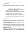
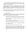
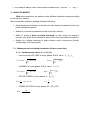
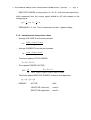
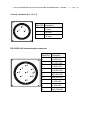
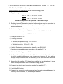
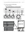
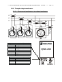
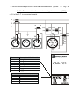
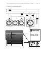
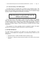
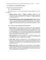
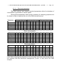
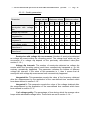
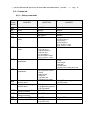
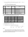
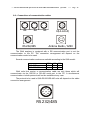
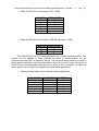
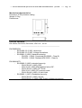
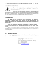
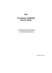
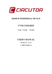
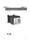
ANALYZER OF THE QUALITY OF
ELECTRIC POWER SUPPLY
QNA-202
(Cód. 771101 / 771102 / 771103)
USER’S MANUAL
( M 981 551 / 01 E )
(c)
CIRCUTOR S.A.
---- ANALYZER OF THE QUALITY OF ELECTRIC POWER SUPPLY QNA-202
MANUAL CONTENTS
1.-
------ Page 1
page
BASIC INSTRUCTIONS .................................................................................... 3
1.1.- Checking the contents of your package........................................................... 3
1.2.- QNA-202 models. ............................................................................................ 3
1.3.- Safety warnings ............................................................................................... 4
1.4.- Operation instructions...................................................................................... 4
2.-
MAIN FEATURES.............................................................................................. 5
2.1.- Basic features .................................................................................................. 5
2.2.- Electrical features ............................................................................................ 6
3.-
ANALYSIS MODES ........................................................................................... 7
3.1.- Measured and calculated parameters (4-wire connection) .............................. 7
3.1.1.- Instantaneous values (L1, L2 & L3) ........................................................... 7
3.1.2.- Instantaneous three-phase values............................................................. 8
3.2.- Measured and calculated parameters (delta connection) ................................ 9
3.2.1.- Instantaneous values (L1, L2 & L3) ........................................................... 9
3.2.2.- Instantaneous three-phase values........................................................... 10
4.-
DATA COLLECTION IN MEMORY (AUTOMATIC MODE).............................. 10
5.-
INSTALLATION & STARTUP .......................................................................... 11
5.1.- Selecting the connection mode...................................................................... 11
5.1.1.- Selecting the connection mode (3 wires / 4 wires)................................... 12
5.1.2.- Selecting the supply voltage .................................................................... 12
5.2.- Connection cables ......................................................................................... 13
5.3.- Starting the QNA analyzer up ........................................................................ 15
5.4.- Connection diagrams of the QNA analyzer.................................................... 16
5.4.1.- Direct connection ..................................................................................... 16
5.4.2.- Through voltage transformers:................................................................. 19
5.5.- On-board battery of the QNA analyzer........................................................... 22
6.-
SETTING THE QNA UP .................................................................................. 22
6.1.- Operation setup of the QNA analyzer ............................................................ 23
6.1.1.- Transformation ratios............................................................................... 23
6.1.2.- Features of the monitored electrical network ........................................... 23
---- ANALYZER OF THE QUALITY OF ELECTRIC POWER SUPPLY QNA-202
------ Page 2
6.1.3.- Data collection process features.............................................................. 24
6.1.4.- Statistical processing ............................................................................... 25
6.1.5.- Quality parameters .................................................................................. 26
6.1.6.- Setting recording conditions (Trigger)...................................................... 26
6.2.- Choosing the parameters to be recorded ...................................................... 27
6.2.1.- Standard file (STD) .................................................................................. 27
6.3.- Events file ...................................................................................................... 30
QNA COMMUNICATIONS........................................................................................ 31
6.4.- Demand format .............................................................................................. 31
6.5.- Commands .................................................................................................... 32
6.5.1.- Setup commands..................................................................................... 32
6.5.2.- Commands for parameter readout........................................................... 33
6.5.3.- File managing commands........................................................................ 34
6.6.- Connections of communication cables .......................................................... 35
7.-
TECHNICAL SPECIFICATIONS...................................................................... 37
8.-
SAFETY CONSIDERATIONS.......................................................................... 39
9.-
MAINTENANCE............................................................................................... 39
10.- TECHNICAL SERVICE.................................................................................... 39
---- ANALYZER OF THE QUALITY OF ELECTRIC POWER SUPPLY QNA-202
------ Page 3
1.- BASIC INSTRUCTIONS
This manual is aimed to familiarize the user with the operation of the power
supply quality analyzer model QNA in order to get the best from its features.
QNA analyzers have been built with components incorporating the most
advanced technology in microelectronics, and offer benchtop features for the market
in terms of measuring and recording of electrical magnitudes in industrial power
supply networks.
You are kindly requested to carefully read this manual before connecting
and powering the analyzer in order to avoid irreversible damage which might be
caused by an improper connection.
1.1.- Checking the contents of your package
After receiving the analyzer, please check the following points:
a) The delivered material meets your order specifications.
b) After unpacking, check that the instrument has not been damaged in
transit.
c) The standard set includes the following items:
3 female 4-pin connectors.
1 female 7-pin connector.
1 female 9-pin connector.
1 female DB9 connector.
1 User’s guide for the QNA.
1 User’s guide for the Software.
1 CD containing the software for PC.
1 GSM antenna (only for the GSM model).
1.2.- QNA-202 models.
Code
Model
771 101
QNA RS-232/RS-485
771 103
QNA GSM (Free – SIM not included)
---- ANALYZER OF THE QUALITY OF ELECTRIC POWER SUPPLY QNA-202
------ Page 4
1.3.- Safety warnings
The manual you hold in your hands contains information and
warnings about the QNA that the user should respect in order to
guarantee a proper operation of all the instrument functions and
keep its safety conditions.
If the instrument is not used as manufacturer’s specifications, the
protection of the instrument can be damaged.
When any protection failure is suspected to exist (for example, it presents
external visible damages), the instrument must be immediately powered OFF. In this
case contact a qualified service representative.
1.4.- Operation instructions
The QNA is a programmable instrument, so offering diverse operation modes
which can be selected from the available programming menus.
Please, before initiating works with the QNA, thoughtfully read the paragraphs
involving INSTALLATION & STARTUP AND SETTING THE QNA UP, in order to
select the most suitable operation mode for your requirements.
Note that with the instrument powered on, the terminals could be dangerous to
touching, and cover opening actions or elements removal may allow the
access to dangerous parts. Therefore, the instrument must not be used until
this is completely installed.
---- ANALYZER OF THE QUALITY OF ELECTRIC POWER SUPPLY QNA-202
------ Page 5
2.- MAIN FEATURES
The QNA network analyzer is an instrument specifically designed for the
accomplishment of monitoring actions over the electric network. Among their main
characteristics, we can remark following:
•
High protection level against severe electrical conditions:
− Wide range of both supply and measuring voltages.
− High protection level against overvoltage and transient events.
•
Connection to either 3 or 4 wire distribution systems.
•
Inner battery which permits the instrument to go on recording works even in
case of supply voltage loss.
•
Inner memory for saving all parameters measured by the QNA.
•
Communication via GSM / RADIO / RS-232 / RS-485 (according to the
model).
•
IP-65 rated instrument. High protection against adverse environmental
conditions.
2.1.- Basic features
The QNA series analyzer is an instrument specially designed for the analysis of
the electric network quality, for that reason, all inputs for voltage and current signals
are isolated by means of transformers.
Moreover, the great variety of available models makes the QNA suitable for any
situation and communication mode.
The inner battery of the instrument assures the continuity of the measuring
process in case of any supply voltage loss event (short or long-term line interruption).
The standard analyzer is equipped with three A.C. voltage inputs and three A.C.
current inputs (through current transformers) which permit a simultaneous
measurement of voltage and current from all three phases, together with the
frequency, in any power system.
By means of an internal microprocessor, the instrument calculates the rest of
main electrical parameters such as the power factor, active power, inductive or
capacitive reactive power of the three phases, as well as the active and reactive
(inductive and capacitive) energies.
---- ANALYZER OF THE QUALITY OF ELECTRIC POWER SUPPLY QNA-202
------ Page 6
To perform the analysis of the quality of the electric network, the QNA will analyze
all cycles from all three voltage phases to detect the occurrence of any event (voltage
dips, short and long line interruptions,...).
QNA analyzers are equipped with an on-board memory (1 Mb or 3 Mb
according to the model) for the collection of quality parameters as well as of main
electrical parameters in 4 quadrants (energy generation and consumption).
Measured and calculated data are periodically saved into that memory at userdefined time intervals (selectable from 1 s to 4 hours) for a further retrieval from a
PC.
The QNA also records an events file in which any possible incident is stored
(Power ON/OFF, voltage loss at any phase, Setup modification, memory erasure,
change of the time of the on-board clock,...).
2.2.- Electrical features
The application of the QNA as a recording instrument for the evaluation of the
quality of the electrical power supply implies the need that this analyzer must deliver
a high protection degree against severe electrical conditions:
•
Protective devices in voltage inputs: Special type fuses able to withstand
short-term pulses, which considerably increases the instrument efficiency.
•
High-energy varistors for the absorption of surges in order to avoid
possible costly repairs.
•
Noise filters in voltage and current inputs to assure reliable measurements
even under most adverse operation conditions.
•
Power supply: transformers with an over power dissipation and insulation.
•
Power supply by built-in battery to assure a voltage supply to the QNA in
case of voltage loss failure.
•
Insulation transformers to guarantee the proper insulation of inputs.
•
Enclosure: The case made of aluminium casting provides a great
mechanical toughness, but also an exceptional shield against external
electromagnetic fields which might appear in extreme situations. Logical
and measuring boards are placed inside a separated zone which even
increases the screening of sensitive components by “Faraday’s cage”
effect.
---- ANALYZER OF THE QUALITY OF ELECTRIC POWER SUPPLY QNA-202
------ Page 7
3.- ANALYSIS MODES
QNA series analyzers can perform under different operation modes according
to the previous setting.
Most remarkable operation settings are these following:
•
Measurement and collection in memory of main electrical parameters from any
power distribution system.
•
Selection of electrical parameters to be saved into memory.
•
Ability of setting a data recording threshold, so that values are saved in
memory only when values exceed or lower limits of the user-defined threshold.
•
Setting of a voltage threshold to define diverse event occurrences (Quality,
voltage sags, line interruptions).
3.1.- Measured and calculated parameters (4-wire connection)
3.1.1.- Instantaneous values (L1, L2 & L3)
-
Line-to-neutral VOLTAGE of every phase, R.M.S. value: V1, V2, V3.
Vn = Vrms =
-
1
N
Vrms =
N
1
(U ) 2
1
i (t ) 2 ⋅ dt
T
; Irms =
1
N
N
1
(i ) 2
ACTIVE POWER of every phase: P1, P2, P3.
Pn =
-
;
CURRENT of every phase, R.M.S. value: I1, I2, I3.
In = Irms =
-
1
u (t ) 2 ⋅ dt
T
1
u (t ) ⋅ i (t ) ⋅ dt
T
;
P=
1
N
N
1
u ⋅i
POWER FACTOR of every phase: PF1, PF2 y PF3.
PFn =
Pn
Irms ⋅ Vrms
---- ANALYZER OF THE QUALITY OF ELECTRIC POWER SUPPLY QNA-202
-
------ Page 8
REACTIVE POWER of every phase: Q1, Q2, Q3 (inductive and capacitive).
Value measured from the current signal shifted by 90º with respect to the
voltage signal.
Qn =
-
π
1
u (t ) ⋅ i (t + ) ⋅ dt
T
2
FREQUENCY: F (Hz) This is measured over the L1 phase voltage.
3.1.2.- Instantaneous three-phase values
-
Average VOLTAGE from the three phases:
Vm =
-
Average CURRENT from the three phases:
Im =
-
Vrms1 + Vrms 2 + Vrms3
3
Irms1 + Irms 2 + Irms3
3
Total three-phase ACTIVE POWER:
Pt = P1 + P 2 + P3
-
Three-phase POWER FACTOR:
PFm =
-
Pt
P1 + P 2 + P3
=
St Ims1 ⋅ Vrms1 + Irms2 ⋅ Vrms2 + Irms3 ⋅ Vrms3
Total three-phase REACTIVE POWER (inductive and capacitive):
Qt = Q1 + Q 2 + Q3
-
ENERGY:
- ACTIVE
: kWh
- REACTIVE (inductive)
: kvarLh
- REACTIVE (capacitive) : kvarCh
---- ANALYZER OF THE QUALITY OF ELECTRIC POWER SUPPLY QNA-202
------ Page 9
3.2.- Measured and calculated parameters (3 - wires)
3.2.1.- Instantaneous values (L1, L2 & L3)
-
Line-to-line VOLTAGE of every phase, R.M.S. value: V12, V23, V31.
Vn = Vrms =
-
1
i (t ) 2 ⋅ dt
T
1 u (t )
× i (t )dt
T
3
(U ) 2
; Irms =
1
N
N
1
(i ) 2
;
P=
1
N
N
1
U ×i
3
POWER FACTOR of every phase: PF1, PF2 y PF3.
PFn =
-
N
1
ACTIVE POWER of every phase: P1, P2, P3.
Pn =
-
1
N
Vrms =
;
CURRENT of every phase, R.M.S. value: I1, I2, I3
In = Irms =
-
1
u (t ) 2 ⋅ dt
T
Pn 3
Irms × Urms
REACTIVE POWER of every phase: Q1, Q2, Q3 (inductive and capacitive).
Qn =
1 u (t ) × i (t + π / 2)
.dt
T
3
Value measured from the current signal shifted by 90º with respect to the
voltage signal.
-
FREQUENCY: F (Hz) This is measured over the L1 phase voltage.
---- ANALYZER OF THE QUALITY OF ELECTRIC POWER SUPPLY QNA-202
------ Page 10
3.2.2.- Instantaneous three-phase values
-
Average VOLTAGE from the three phases:
Vm =
-
CURRENT of every phase, R.M.S. value: I1, I2, I3
Im =
-
Vrms1 + Vrms 2 + Vrms3
3
Irms1 + Irms 2 + Irms3
3
Total three-phase ACTIVE POWER:
Pt = P1 + P 2 + P3
-
Three-phase POWER FACTOR:
PFm =
-
Pt
P1 + P 2 + P3
3
=
St Irms1 × Vrms1 + Im s 2 × Vrms 2 + Im s3 × Vrms3
Total three-phase REACTIVE POWER (inductive and capacitive):
Qt = Q1 + Q 2 + Q3
-
ENERGY:
- ACTIVE:
kWh
- REACTIVE (inductive):
kvarLh
- REACTIVE (capacitive):
kvarCh
4.- DATA COLLECTION IN MEMORY (AUTOMATIC MODE)
The QNA is equipped with an internal clock for both date and time that permits
setting the automatic data recording process in memory (available capacity according
to the model) at regular time periods.
The choice of the recording period and the need of this action will depend on
the previously programmed parameters.
Parameters to be saved into memory are user-programmable, so that, the
analyzer versatility is enhanced and the number of registers that can be stored is
also increased.
The QNA also records in memory an events file into which any possible incident
in the own QNA or in the monitored line will be saved (Power ON/OFF, voltage loss
at any phase, Setup modification, memory erasure, change of the time of the onboard clock,...).
---- ANALYZER OF THE QUALITY OF ELECTRIC POWER SUPPLY QNA-202
------ Page 11
5.- INSTALLATION & STARTUP
The manual you hold in your hands contains information and warnings
that the user should respect in order to guarantee a proper operation of
all the instrument functions and keep its safety conditions.
If the instrument is not used as manufacturer’s specifications, the
protection of the instrument can be damaged. Notice that with the instrument
powered on, the terminals could be dangerous to touching and cover opening actions
or elements removal may allow the access to dangerous parts.
When any protection failure is suspected to exist (for example, it presents
external visible damages), the instrument must be immediately powered OFF.
In this case contact a qualified service representative.
5.1.- Selecting the connection mode
The QNA is a fully user-configurable instrument in terms of the kind of network to
be monitored and the supply voltage of the analyzer.
The QNA can be indistinctly installed in a three-phase distribution line with neutral
conductor (4 wires) or without neutral conductor (3 wires).
The choice of the voltage supply and the connection mode is carried out by
means of some bridges placed inside the QNA casing. Please always check the
position of this bridges before connecting and powering the QNA.
Before any adjustment operation is carried out, the QNA must
be completely disconnected from any power supply source.
*(C-3)
PF8
PF7
PF6
M2
*(D-2)
PF5
PF4
PF3
M3
*(D-1)
*(C-1)
M4
*(C-2)
*(D-3)
M9
M8
*(B-3)
M5
M10
*(B-1)
*(D-6)
M11
*(B-2)
M6
M12
*(A-3)
*(D-7)
M13
*(A-1)
M7
M15
M14
*(A-2)
*(X-N)
*(X-N)
*(X-N)
PF1
PF2
*(D-4)
(TIERRA)
MODEM
3 / 4 WIRES
CONNECTION
TERMINAL
POWER SUPPLY
CONNECTION
TERMINAL
---- ANALYZER OF THE QUALITY OF ELECTRIC POWER SUPPLY QNA-202
------ Page 12
5.1.1.- Selecting the connection mode (3 wires / 4 wires)
The arrangement of the distribution system to be monitored by the QNA can
be selected by means of an inner bridge placed inside the QNA casing. Thus, the
QNA will perform the analysis of the voltage incidences according to the position of
this bridge, that is, voltage events will be detected between phase and neutral for the
4-wire arrangement, and, on the other side, these events will be detected over lineto-line voltages for the 3-wire arrangement.
As for the former case, first of all assure that the QNA is completely
disconnected from the monitored main (both power supply and measuring circuits),
and then remove the frontal cover of the QNA. Check that the position of the bridges
agrees with the desired system arrangement.
Finally, set also the selected configuration in the PC software, since both
settings must always fully coincide.
4-wire configuration
3-wire configuration:
Connector position:
Up
Connector position:
Down
Connector position:
Up (J1)
Connector position:
Down (J4)
5.1.2.- Selecting the supply voltage
The supply voltage of the QNA for any particular application can be selected
by means of an inner bridge placed inside the QNA casing.
First of all, assure that the QNA is completely disconnected from the
monitored main (both power supply and measuring circuits), and then remove the
frontal cover of the QNA. Check that the position of the bridge agrees with the
desired voltage supply.
Power supply:
230 V~
Power supply:
400 V
Connector position:
Up
Connector position:
Down
---- ANALYZER OF THE QUALITY OF ELECTRIC POWER SUPPLY QNA-202
------ Page 13
5.2.- Connection cables
IL1
IL2
RS 232/485
IL3
U(L1-L2-L3)
Antena Radio / GSM
Voltage connector U(L1, L2, L3):
QNA PIN Description
1
3
2
5
4
6
7
1
Voltage UL1
2
Voltage UL3
3
Voltage UL2
4
Earthing terminal
5*
Neutral
6
Supply UAL1
7
Supply UAL2
* Note: This connection is not required when the monitored distribution system has
no neutral conductor.
The connection of the earthing terminal to the system
earth is essential to assure the efficiency of QNA
protective elements.
---- ANALYZER OF THE QUALITY OF ELECTRIC POWER SUPPLY QNA-202
Current connector I(L1, L2, L3):
QNA PIN Description
1
2
3
1
1A input
2
Common
3
5 A input
RS-232/RS-485 communication connector:
QNA PIN Description
1
2
3
5
4
6
8
7
9
1
RX (RS-232)
2
CTS (RS-232)
3
TX (RS-232)
4
RTS (RS-232)
5
DSR (RS-232)
6
GND (RS-232)
7
RX (RS-485)
8
TX (RS-485)
9
GND (RS-485)
------ Page 14
---- ANALYZER OF THE QUALITY OF ELECTRIC POWER SUPPLY QNA-202
------ Page 15
5.3.- Starting the QNA analyzer up
Before powering the analyzer on please check following points:
1) Supply voltage:
230 V~ +40 % / -40 %, 50... 60 Hz.
400 V~ +40 % / -40 %, 50... 60 Hz.
This choice depends on the position of the inner bridge.
2) Earthing terminal: The earthing terminal of the analyzer must be connected to
earth. The lack of this connection implies the inefficiency of some instrument
protective elements.
3) Maximum voltage in the voltage measuring circuit:
4-wire arrangement 500 V~ line-to-neutral. / 866 V~ line-to-line.
3-wire arrangement: 500 V~ line-to-line.
4) Analyzer burden: 6 VA.
5) Working conditions:
•
Working temperature range: 0 ºC to 50 ºC.
•
Working humidity: 25% to 75 % RH.
6) Safety: Designed to meet protection class III as per EN 61010.
7) Maximum measurable current: according to the applied C.T.’s.
Points to check during the installation process:
8) Verify that the earthing terminal of the QNA is connected to the earth in order
to avoid possible interferences over the analyzer to occur. If this earthing
terminal is not connected, then the efficiency of the QNA protection elements
would be reduced.
9) Assure that the applied C.T.’s have been installed in the right phase in terms
of the correspondence of every current and voltage phase.
10) Respect the polarity and connection mode of the applied C.T.’s.
11) Verify the QNA setup.
12) Respect the connection modes shown at each following attached diagrams to
correctly achieve powers, PF, and energies readouts.
---- ANALYZER OF THE QUALITY OF ELECTRIC POWER SUPPLY QNA-202
------ Page 16
5.4.- Connection diagrams of the QNA analyzer
5.4.1.- Direct connection
5.4.1.1.- Connection diagram for L.V. 4-wire power systems
L1
L2
P1
P2
S1
S2
L3
P1
P2
S1
S2
N
1A
5A
1A
P2
S1
S2
1A 5A
1
1
2
5A
P1
3
2
Power Supply
0 - 230 - 400V
1
1
3
2
3
3
Current connection terminal I (L1, L2, L3)
QNA Pin Description
1
Input 1A
2
Common
3
Input 5A
4
No used
5
4
6
Voltage connection terminal U (L1, L2, L3)
QNA Pin
Description
1
Voltage U L1
2
Voltage U L3
3
Voltage U L2
4
Earthing terminal
5
Neutral
6
Supply U AL1
7
Supply U AL2
2
7
QNA-202
---- ANALYZER OF THE QUALITY OF ELECTRIC POWER SUPPLY QNA-202
------ Page 17
5.4.1.2.- Connection diagram for 3-wire power systems (delta connection)
L1
L2
P1
P2
S1
S2
L3
5A
1A
P1
P2
S1
S2
P2
S1
S2
3
2
5A
1A
1
1
2
5A
1A
P1
Power Supply
0 - 230 - 400V
1
1
3
2
3
3
Current connection terminal I(L1, L2, L3)
QNA Pin Description
1
Input 1A
2
Common
3
Input 5A
4
No used
5
4
6
Voltage connection terminal U (L1, L2, L3)
QNA Pin
Description
1
Voltage U L1
2
Voltage U L3
3
Voltage U L2
4
Earthing terminal
5
No used
6
Supply U AL1
7
Supply U AL2
2
7
QNA-202
---- ANALYZER OF THE QUALITY OF ELECTRIC POWER SUPPLY QNA-202
------ Page 18
5.4.1.3.- Connection diagram for 3-wire power systems in ARON mode.
L1
L2
P1
P2
S1
S2
L3
1A
5A
P2
S1
S2
1A
1
1
2
P1
3
2
5A
Power Supply
0 - 230 - 400V
1
1
3
2
3
3
Current connection terminal I(L1, L2, L3)
QNA Pin Description
1
Input 1A
2
Common
3
Input 5A
4
No used
5
4
6
Voltage connection terminal U (L1, L2, L3)
QNA Pin
Description
1
Voltage U L1
2
Voltage U L3
3
Voltage U L2
4
Earthing terminal
5
No used
6
Supply U AL1
7
Supply U AL2
2
7
QNA-202
---- ANALYZER OF THE QUALITY OF ELECTRIC POWER SUPPLY QNA-202
------ Page 19
5.4.2.- Through voltage transformers:
5.4.2.1.- Three current transformers + two voltage transformers
L2
P1
P2
S1
S2
L3
5A
1A
P1
P2
S1
S2
P2
S1
S2
3
2
(P1)A
B(P2)
(P1)A
B(P2)
(S1)a
b(S2)
(S1)a
b(S2)
5A
1A
1
1
2
5A
1A
P1
1
1
3
2
3
2
3
6
Voltage connection terminal U (L1, L2, L3)
QNA Pin
Description
1
Voltage U L1
2
Voltage U L3
3
Voltage U L2
4
Earthing terminal
5
No used
6
Supply U AL1
7
Supply U AL2
Current connection terminal I (L1, L2, L3)
QNA Pin Description
1
Input 1A
2
Common
3
Input 5A
4
No used
5
4
7
(P1)A
B(P2)
(S1)a
b(S2)
Alimentación
0 - 230 - 400V
L1
QNA-202
---- ANALYZER OF THE QUALITY OF ELECTRIC POWER SUPPLY QNA-202
------ Page 20
5.4.2.2.- Two current transformers + two voltage transformers (ARON).
S1 of the C.T. is connected to earth.
L1
L2
P1
P2
S1
S2
L3
S1
S2
1
1
2
P2
1A
5A
1A
P1
3
2
(P1)A
B(P2)
(P1)A
B(P2)
(S1)a
b(S2)
(S1)a
b(S2)
5A
1
1
3
2
3
2
3
6
Voltage connection terminal U (L1, L2, L3)
QNA Pin
Description
1
Voltage U L1
2
Voltage U L3
3
Voltage U L2
4
Earthing terminal
5
No used
6
Supply U AL1
7
Supply U AL2
Current connection terminal I(L1, L2, L3)
QNA Pin Description
1
Input 1A
2
Common
3
Input 5A
4
No used
5
4
7
(P1)A
B(P2)
(S1)a
b(S2)
Alimentación
0 - 230 - 400V
•
QNA-202
---- ANALYZER OF THE QUALITY OF ELECTRIC POWER SUPPLY QNA-202
S2 of the C.T. is connected to earth.
L1
L2
P1
P2
S1
S2
L3
5A
1A
P2
S1
S2
1
3
2
(P1)A
B(P2)
(P1)A
B(P2)
(S1)a
b(S2)
(S1)a
b(S2)
5A
1A
1
2
P1
1
1
3
2
3
2
3
6
Voltage connection terminal U (L1, L2, L3)
QNA Pin
Description
1
Voltage U L1
2
Voltage U L3
3
Voltage U L2
4
Earthing terminal
5
No used
6
Supply U AL1
7
Supply U AL2
Current connection terminal I (L1, L2, L3)
QNA Pin Description
1
Input 1A
2
Common
3
Input 5A
4
No used
5
4
7
(P1)A
B(P2)
(S1)a
b(S2)
Alimentación
0 - 230 - 400V
•
------ Page 21
QNA-202
---- ANALYZER OF THE QUALITY OF ELECTRIC POWER SUPPLY QNA-202
------ Page 22
5.5.- On-board battery of the QNA analyzer
The QNA analyzer is equipped with an intelligent energy charging system. This
means that the instrument continuously checks in an automatic way the status of the
battery, thus the charging process stops when the battery is at its maximum charge
level and, therefore, the span life of the battery is increased.
When the analyzer is connected to the main, the
battery is self-recharging.
The analyzer has an inner battery to assure the power supply of the analyzer
when any event occurs. This battery permits to keep the analyzer continuously
energized during 4 hours in case of lack of voltage supply from the main. This period
of time of operation after a voltage supply loss is user-programmable in order to
economize the battery charge, to assure the detection of possible intermittent voltage
interruptions.
The warranty of a 4-hour operation period is essential to assure the proper
detection and recording of multiple and long-term voltage interruptions.
6.- SETTING THE QNA UP
The QNA analyzer performance will depend on the user-configuration of the
instrument. To accomplish this configuration, two different setup sections can be
distinguished:
•
Operation Setup: To define the QNA analyzer operation mode.
•
File Setup: To define the data collection procedure of the QNA into the internal
memory.
---- ANALYZER OF THE QUALITY OF ELECTRIC POWER SUPPLY QNA-202
------ Page 23
6.1.- Operation setup of the QNA analyzer
Points to be user-defined are following:
6.1.1.- Transformation ratios
The QNA analyzer can take measurements through voltage and current
transformers.
•
Voltage primary value / Voltage secondary value: Set the
transformation ratio of voltage transformers used for measuring purposes.
In case of a direct measurement of the voltage (no voltage transformer
used) then just set 1/1.
•
Current primary value / Current secondary value: The measuring of
current by the QNA analyzer can be effectuated through either ../ 5 A or
../1A C.T. Set at this point the transformation ratio of C.T.’s used for
measuring purposes. Check that the C.T. secondary circuit is connected to
the right current signal input since different inputs are provided for ../ 1A or
.../5A.
6.1.2.- Features of the monitored electrical network
•
Rated voltage: The rated voltage of the power system to be monitored by
the QNA. When the measurement is direct, that is, no voltage transformer
is used, then this voltage matches the network rated voltage. If any .../110
V~ voltage transformer is used, then the rated voltage to be set results
from the application over the network rated voltage of the transformation
ratio. A right configuration of this point is essential since permits setting the
limits for the analysis of power supply quality.
•
Rated frequency: The rated frequency of the power system to be
monitored by the QNA. This parameter is necessary for the calculation of
the signal R.M.S. value in extreme quality networks.
•
Circuit type: When the measurement is done through three current
probes, then the analyzer must be set to work with a three-phase circuit. In
the case of 3-wire networks, that is, networks without neutral conductor,
the analyzer can be set to work in ARON system so that only two current
probes are required.
•
Measurement type: The QNA must be set according to the distribution
system to be monitored, whether with neutral conductor (4 wires) or without
neutral conductor (3 wires). A proper setting of this point is essential to
assure a right detection of event occurrences. This choice must also match
the inner bridge position (See section 5.1.1.-)
---- ANALYZER OF THE QUALITY OF ELECTRIC POWER SUPPLY QNA-202
------ Page 24
6.1.3.- Data collection process features
•
File name: Name of the file to be used for data recording (not modifiable).
•
Recording period: Integration period for data recording into memory of all
selected parameters. Average, maximum and minimum values obtained
along the period will be recorded.
•
Period of voltage sliding window: To carry out the calculation of the
average, maximum and minimum voltage, the QNA obtains one value each
second. This instantaneous value corresponds to the average of Vrms
values which have been calculated within the sliding window defined by the
user (voltage time constant). If this period is set to 1 s, then the
instantaneous value equals the Vrms value.
•
Period of frequency sliding window: To carry out the calculation of the
average, maximum and minimum frequency, the QNA obtains one value
each second. This instantaneous value corresponds to the average of
frequency values which have been calculated within the sliding window
defined by the user (frequency time constant). If this period is set to 1 s,
then this value equals the instantaneous frequency.
---- ANALYZER OF THE QUALITY OF ELECTRIC POWER SUPPLY QNA-202
------ Page 25
6.1.4.- Statistical processing
•
Confidence level for the voltage (%): For each record, the analyzer
saves in memory a maximum and minimum voltage value within a predefined confidence interval. The confidence level (expressed in
percentage) indicates the percentage of measures which must be
considered for analysis purposes inside the confidence interval, by
neglecting extreme values. For instance, if a confidence level of 95 % is
set, then the 2.5% of lowest values and the 2.5% of highest values would
be neglected. Inside the interval, the maximum and minimum values are
obtained and recorded.
If the user want to record the maximum and minimum values taking into
account all measurements (absolute values), then a confidence level of
100 % should be set.
Vrms histogram
User configurable between
51% and 100%
V% threshold
V% threshold
Vmax
•
Vmin
Vrms-1s
Confidence level for the frequency (%): An analogue processing
performed by the QNA-202 over the voltage can be optionally applied over
the frequency. If the user want to record the absolute maximum and
minimum values, then a confidence level of 100 % should be set.
Hz histogram
User configurables between
51% and 100%
Hz% threshold
Hz max
Hz% threshold
Hz min
Hz-1seg
---- ANALYZER OF THE QUALITY OF ELECTRIC POWER SUPPLY QNA-202
------ Page 26
6.1.5.- Quality parameters
•
% of voltage dip: The detection of a voltage dip depends on the value set in
this point (% of the rated voltage). Every semicycle whose R.M.S. value is
below the defined limit value is stated to be a voltage dip. The analyzer will
indicate the number of cycles which have not reached the defined voltage
value and if these semicycles have successively occurred (intervals).
•
% of voltage for Power OFF event / Seconds for Power OFF event: We will
consider as a power OFF (voltage loss, line interruption) the voltage drop
below a defined value (% of the rated voltage) during a determined period of
time. These two parameters are used to define the power OFF event.
•
% of correct voltage for high voltage event / % of correct voltage for low
voltage event: Two limits to define a voltage range outside from which the
quality of the voltage is not correct, can be also set by the user. The period of
time during which the voltage has kept within these defined limits is also
indicated. The values for these limits are defined as a % of the set rated
voltage.
% of seconds (N) that Vrms-1s
is within thresholds
V
n1
n2
Vq
Vq
Vnom
Treg
N = (n1+n2)/Trec
t
Vq=Threshold_Q% x Vnom
6.1.6.- Setting recording conditions (Trigger)
You can set certain conditions (Trigger) so that values are saved into memory
only when these conditions are met.
-
To record values in memory, the two user-defined TRIGGER conditions must
be simultaneously met, if any condition is not met, then no data will be saved
into memory.
-
If the trigger conditions are disabled, then values will be always saved into
memory according the user-defined recording period.
-
If the trigger conditions are simultaneously met at any moment within the
selected recording period, then average values over all the period will be
saved into memory.
---- ANALYZER OF THE QUALITY OF ELECTRIC POWER SUPPLY QNA-202
------ Page 27
Two types of trigger conditions are available:
•
•
Time trigger (Start/ End date): Setting of dates and times for the starting
and ending actions of the recording process.
-
To disable the time trigger, all values must be set to zero.
-
If only START/END times are set (two dates set to zero), then the
defined recording period will be daily repeated.
Level trigger: Setting of a parameter to be used as a trigger condition, as
well as its maximum and minimum range-limiting values. You must here
process as follows:
-
Trigger parameter: Choice of the parameter to be used as the
trigger condition for data recording actions.
-
Maximum / Minimum trigger value: Values will be saved into
memory when either the instantaneous value of any of the three
phases (L1, L2 or L3) or the three phase value of the selected
parameter is higher than the maximum or lower than the minimum
set value.
Parameter
Vp-p
Vp-n
A
kW
kvarL
kvarC
PF
Hz
kVA
Admissible values
0 999999
0 999999
0 9999999
-9999999 9999999
-9999999 9999999
-9999999 9999999
-1.00 1.00
40.0 99.9
0 9999999
6.2.- Choosing the parameters to be recorded
Parameters to be recorded by the QNA in its internal memory are user-definable,
so that, you can always obtain the maximum efficiency from the instrument memory
capacity at each particular situation by saving only useful information (maximum of
100 parameters).
6.2.1.- Standard file (STD)
The standard file (STD) is used to store all parameters which are periodically
recorded. These parameters can be classified into diverse groups:
---- ANALYZER OF THE QUALITY OF ELECTRIC POWER SUPPLY QNA-202
------ Page 28
6.2.1.1.- Electrical parameters
The QNA analyzer can measure electrical parameters either for situations of
consumption or generation of electric power.
Among these parameters, these strictly necessary for analyzing purposes can
be chose in order to optimize the use of the QNA internal memory.
Parameter
Vp-p
Vp-n
A
Hz x 10
kVA
Average values
Maximum values
L1 L2 L3 LIII L1 L2 L3 LIII
X
X
X
X
X
X X
X
X
X
X
X
X
X X
X
X
X
X
X
X
X X
X
X
X
X
X
Minimum values
L1 L2
L3
X
X
X
X
X
X
X
X
X
X
LIII
X
X
X
X
Power consumption
+kW
+kvarL
+kvarC
+PFx100
+kWh
+kvarLh
+kvarCh
X
X
X
X
X
X
X
X
X
X
X
X
X
X
X
X
X
X
X
X
X
X
X
X
X
X
X
X
X
X
X
X
X
X
X
X
X
X
X
X
X
X
X
X
X
X
X
X
X
X
X
X
X
X
X
X
X
X
X
X
X
X
X
X
X
X
X
X
X
X
X
Power generation
-kW
-kvarL
-kvarC
-PFx100
-kWh
-kvarLh
-kvarCh
X
X
X
X
X
X
X
X
X
X
X
X
X
X
X
X
X
X
X
X
X
X
X
X
X
X
X
X
X
X
X
Note: When selecting the parameters to be recorded, check that selected parameters
are coherent with the connection arrangement (3 wire / 4 wire) set in the QNA
analyzer.
---- ANALYZER OF THE QUALITY OF ELECTRIC POWER SUPPLY QNA-202
------ Page 29
6.2.1.2.- Quality parameters
Parameter
Average values
Maximum values
L1
L2
L3
X
X
X
Voltage dip intervals
X
X
X
Integrated Hz
X
Integrated V
X
X
X
X
X
X
% of voltage quality
X
X
X
X
X
X
Wave form V
X
X
X
Wave form I
X
X
X
Semicycles
dips
with
voltage
L1
L2
L3
X
Minimum values
L1
L2
L3
X
X
X
X
X
X
X
Semicycles with voltage dip occurrences: Number of semicycles detected
as voltage dip events within the recording period. The voltage level which set the
occurrence of a voltage dip depend on the previously user-defined value.(See
section 6.1.5.-)
Voltage dip intervals: The number of semicycles detected as voltage dip
events within the recording period could have consecutively happened or, on the
contrary, sporadically happened. This parameter indicates the number of different
voltage dip intervals. If the value of this parameter is 1, then it means that all
semicycles with voltage dip occurrences have consecutively happened.
Integrated Hz: This parameters equals the value of the frequency obtained
after the measurement by the application of the user-defined time constant which
have been defined in section 6.1.4.Integrated V: This parameter equals the value of the voltage obtained after
the measurement by the application of the user-defined time constant which have
been defined in section 6.1.4.% of voltage quality: The percentage of time during which the average value
keeps within admissible voltage limits. These limits are set in section 6.1.4.-
---- ANALYZER OF THE QUALITY OF ELECTRIC POWER SUPPLY QNA-202
------ Page 30
6.3.- Events file
The analyzer also records and events file that contains information on the
occurrence moment, duration and minimum voltage of any incidence happening.
These incidences are following:
Power On: Indication of the moment when the QNA is turn on. This moment matches
the moment when the instrument is powered on.
Power OFF: Indication of the moment when the QNA is turn OFF. This moment will
depend on the period of time defined by the user for an operation with a power
supply by the internal battery, or also if any power supply loss occurs.
Setup modification: Record of the moment when any modification of the instrument
Setup is realized.
Memory format: Indication of the moment when the user has decided the QNA
internal memory to be formatted.
Forced memory format: The QNA internal memory will be automatically formatted if
any error in this internal memory is detected.
Delete a file: Indication of the moment when the user has deleted any file from the
QNA internal memory. If the first data shown by the .EVE file is the indication that a
file has been delete, then this means that the deleted file was the events file.
Time change: Indication of any change of the date or time of the analyzer’s on-board
clock. The record of this event type is quite important, since when an illogical interval
of time between two successive readouts are observed in the graphical
representation of any parameter, this might be due to a change of the time of the onboard clock.
Voltage ON L1, Voltage ON L2, Voltage ON L3: Indication of the moment when the
QNA has detected a voltage dip or a line interruption. This value will depend on the
configuration set in the section 6.1.5.-.
Voltage OFF L1, Voltage OFF L2, Voltage OFF L3: Indication of the moment when
the voltage of the instrument exceeds the minimum value; that is, the moment when
the network voltage exceeds the value defined as power OFF voltage (See section
6.1.5.-).
---- ANALYZER OF THE QUALITY OF ELECTRIC POWER SUPPLY QNA-202
------ Page 31
QNA COMMUNICATIONS
One of the main features of the QNA in terms of communications is the use of
the Z-MODEM protocol, both for the data retrieval and the instrument setting actions.
This protocol is specially designed for the transmission via modem links. Main
features of this protocol are following :
− Full-Duplex protocol which gets the maximum efficiency from the link.
− Automatic adaptation of the baud rate to the phone line quality.
− Automatic adaptation of frame length.
− Complete system of error detection and correction.
− The communication is not cut off in case of punctual errors in frames, but
the system tries for several times to resend the same information until the
verification of a complete communication interruption.
The application of this protocol assures to get optimum data transmission times
with a minimum number of incidences.
6.4.- Demand format
PROTOCOL: Question / Answer
The demand format is: $PPCCCAA... ch [LF] (example = $00VER71)
The answer format is: $PPAA... ch [LF]
$
PP
CCC
AA
Ch
[LF]
Any message starts with this symbol (ASCII- 36).
The identification code (00) for the portable QNA (decimal-ASCII).
COMMAND.
ARGUMENT (Decimal- ASCII).
CHECK-SUM : Check-sum of all the elements forming the message. It is
calculated by the decimal addition of all the previous bytes in ASCII and then
translating the result into hexadecimal. Two digits are taken.
example = $00RAL --> 36 + 48 + 48 +82 + 65 + 76 = 355
355 decimal or 163 hexad. CHECK-SUM = 63 ----> $00RAL63 [LF]
LINE FEED indicates the end of the message (ASCII 10).
---- ANALYZER OF THE QUALITY OF ELECTRIC POWER SUPPLY QNA-202
------ Page 32
6.5.- Commands
6.5.1.- Setup commands
COMMAND
CONCEPT
QUESTION
ANSWER
VER
INI
RCL
WCL
Read QNA version
Reset
Read date
Write date
$00 4 digits
$00ACK
$00XX/XX/XX XX:XX:XX
$00ACK
$00ERR
RRT
Read
ratios
$00VER
$00INI
$00RCL
$00WCLXX/XX/XXXX
XX:XX:XX
transformation $00RRT
$00 + (6) Primary U
+ (3) Secondary U
+ (5) Primary I
+(1) Secondary I
+(1) 0–III-fase,1–Aron
+(1) 0–3 wire,1–4 wire
WRT
Write
ratios
transformation $00WRT
$00ACK
RRS
Read
communication $00RRS
parameters
$00 + (2) Peripheral number
+ Parity
+ Data length
+ Stop bits
+ (4) Baud rate
+ (4) Baud rate COM2 (No used)
WRS
Write
communication $00WRS
+(2) Peripheral number
parameters
$00ACK
Read recording
and file name
Write recording
and file name
$00 + (5) Recording period
+ (8) File name
$00ACK
+ (6) Primary U
+ (3) Secondary U
+ (5) Primary I
+(1) Secondary I
+(1) 0–III-fase,1–Aron
+(1) 0–3 wire,1–4 wire
+ Parity
+ Data length
+ Stop bits
+ (4) Baud rate
+ (4) baud rate COM2
RPA
WPA
CLEP
CLEN
RTD
WTD
period $00RPA
period $00WPA
+ (5) Recording period
+ (8) File name
Reset to zero of Positive $00CLEP
Energy counters
Reset to zero of Negative $00CLEN
Energy counters
Read battery OFF time
$00RTD
$00 (4) OFF time
Read battery OFF time
$00WTD
$00ACK ch
+ (4) OFF time
---- ANALYZER OF THE QUALITY OF ELECTRIC POWER SUPPLY QNA-202
------ Page 33
6.5.2.- Commands for parameter readout
COMMAND
CONCEPT
QUESTION
RVQ
RWH
Read voltage quality
Read active energy
$00RVQ
$00RWH
RLH
Read inductive energy
$00RLH
RCH
Read capacitive energy
$00RCH
RAL
Read of all instantaneous $00RAL
parameters
ANSWER
$00 + (9 x 3) ascii char
$00 + 9 positive energy
+ 9 negative energy
$00 + 9 positive energy
+ 9 negative energy
$00 + 9 positive energy
+ 9 negative energy
$00 long parameters[30] hexascii
+ Current units hexascii char
+ Power units hexascii char
The arrangement of parameters in the RAL command is as follows: 30 x 8
bytes in hexa-ASCII format according to above attached order.
[ 0 ] L1
[ 4 ] L1
[ 8 ] L1
[ 12 ] L1
[ 16 ] L1
[ 20 ] L1
[ 24 ] L1
[ 1 ] L2
[ 5 ] L2
[ 9 ] L2
[ 13 ] L2
[ 17 ] L2
[ 21 ] L2
[ 25 ] L2
[ 2 ] L3
[ 6 ] L3
[ 10 ] L3
[ 14 ] L3
[ 18 ] L3
[ 22 ] L3
[ 26 ] L3
[3] =0
[7] M
[ 11 ] M
[ 15 ] III
[ 19 ] III
[ 23 ] III
[ 27 ] M
[ 28 ]
[ 29 ] III
Quality voltage
Energy voltage
Current
Active power
Inductive power
Capacitive power
Power factor (*)
Frequency
Apparent power
- 2 bytes: current units 00 - mA / 01 - A
- 2 bytes: power units
00 - W / 01 - kW
(*) - Power factor (x 100) : If capacitive then 200 are added.
0 ---------------------------- 100 ------------------------ 200
+0.0
Ind.
1.0
Cap
- 0.0
Note:
Quality voltage equals the value of the voltage used for the event monitoring.
Energy voltage equals the value of the voltage used for the energy recording.
Samples taken for this analysis are lower than for the event monitoring due to the
great number of calculations which are required.
---- ANALYZER OF THE QUALITY OF ELECTRIC POWER SUPPLY QNA-202
------ Page 34
Both values can be sometimes be different when an event has occurred due to
the accuracy difference.
6.5.3.- File managing commands
COMMAND
DIN
DIR
CONCEPT
Number
memory
Directory
memory
of
of
QUESTION
files
a
file
ANSWER
in $00DIN
$00 5 digits
in $00DIR
+ 5 File number
$00 + 12 file.ext
+ 7 bytes no.
+ 17 date of file creation
$00FILE NOT FOUND
$00ERR
$00ACK
$00 + 12 file.ext
+ 17 beginning date
+ 17 ending date
+ 6 Bytes no. ASCII
$00ACK
$00ERR
$00 + 17 beginning date
+ 17 ending date (the QNA starts
data transference in ZMODEM)
DEL
Delete a file
$00DEL
+ (12) file.ext
DIF
Consult a file content
$00DIF
+ 12 file.ext
FOR
Format memory
$00FOR
SZC
Ask for a file
$00SZC
+ file.ext
SZP
Ask for a part of a file
$00SZP
+ 12 file.ext
+ 17 beginning date
+ 17 ending date
$00ERR01 File does not exist
$00ACK (the QNA starts data
transference in ZMODEM)
$00ERR00 QNA in Setup menu
$00ERR File does not exist or
beginning date > ending date
Note: Date format is “DD/MM/YY hh:mm:ss” with a length of 17 bytes.
---- ANALYZER OF THE QUALITY OF ELECTRIC POWER SUPPLY QNA-202
------ Page 35
6.6.- Connections of communication cables
IL1
IL2
IL3
U(L1-L2-L3)
RS 232/485
Antena Radio / GSM
The QNA analyzer is equipped with a RS communication port to set the
communication to the PC. The connection arrangement will depend on the
communication mode to be used.
Several communication modes are available according to the QNA model:
GSM
X
QNA GSM
QNA 232/485
485
X
X
232
X
QNA units that require a communication cable are only those which will
communicate via the RS-232 or RS-485 serial port to the PC. A simultaneous
communication via both protocols will not be available at any case.
The protocol to be used in QNA RS-232/RS-485 units will depend on the cable
connection arrangement.
2
1
3
5
4
7
9
6
8
RS 232/485
---- ANALYZER OF THE QUALITY OF ELECTRIC POWER SUPPLY QNA-202
•
Cable for RS-232 communication (PC - QNA)
QNA PIN
1
2
3
4
5
6
•
------ Page 36
FEMALE DB9
3
7
2
8
4
5
Cable for RS-485 communication (RS 485 converter - QNA)
QNA PIN
7
8
9
FEMALE DB9
2
1
5
The QNA RS-232 can be communicated to a PC via an external modem. This
system can be applied in these facilities for which a communication via the
conventional phone line is wanted to be set. The communication cable to be used in
these cases is different, and also the modem unit must be set to have no control of
the DTR and to automatically hold the line on when a call is received. (Consult the
user’s guide of the modem to be used for any particular application).
•
Communication cable for an external modem application.
QNA-303 PIN
1
2
3
4
5
6
MALE DB25
3
5
2
4
6
7
MALE DB9
2
8
3
7
4-6
5
---- ANALYZER OF THE QUALITY OF ELECTRIC POWER SUPPLY QNA-202
------ Page 37
7.- TECHNICAL SPECIFICATIONS
Power supply:
Supply voltage:
Independent from the measuring circuit: 230 or 400 V ± 40 %
Frequency:
50...60 Hz.
Burden:
6 VA
Working temperature: -10...+50 ºC
Auxiliary power supply:
Battery: Ni-M-H
Autonomy: 4 h of continuous operation
Voltage measurement:
Measuring system: 3 wires or 4 wires arrangement (choice by inner connection)
Measuring range: 0 to 500 V~. (line-to-neutral).
4-wire network: 0 to 500 V~ (line-to-neutral).
0 to 866 V~ (line-to-line).
3-wire network: 0 to 500 V~ (line-to-line).
Scale switch:
Automatic.
Other voltages: Through voltage transformers.
Frequency :
45 to 65 Hz.
Current measurement:
Two independent current signal inputs: 0...5 A and 0...1 A
Admissible overload of current circuit: 1.2 In
Other currents:
Through current transformers
Accuracy:
Voltage: 0.5 % of readout ± 1 digit.
Current: 0.5 % of readout ± 1 digit.
Power: 1 % of readout ± 1 digit.
Measuring conditions to assure accuracy class::
- Errors due to external voltage and current transformers not included
- Temperature range : 5 ºC to 45 ºC
- Power factor
: 0.5 to 1
- Measuring range
: between 5 % and 100 %
Internal memory:
Memory size: 1Mb (3 Mb as optional)
Memory configuration: FIFO
---- ANALYZER OF THE QUALITY OF ELECTRIC POWER SUPPLY QNA-202
------ Page 38
Mechanical characteristics:
Enclosure: IP-55 protection casing
Weight: 2.5 kg
Dimensions:
Relevant standards
EN 60664, EN 61010, EN 61036, VDE 110 , UL 94
__________________________________________
EM EMISSION
− EN 61000-3-2 (1995), Harmonics.
− EN 61000-3-3 (1995), Voltage fluctuations.
− EN 50081-2 (1993), Industrial emission.
− EN 55011 (1994): Conducted (EN 55022 - Class B).
− EN 55011 (1994): Radiated (EN 55022 - Class A).
EM IMMUNITY
− EN 50082-2 (1995), industrial immunity.
− EN 61000-4-2 (1995), ESD.
− ENV 50140 (1993), EM Radiated field of RF.
− EN 61000-4-4 (1995), EFT burst.
− ENV 50141 (1993), RF common mode.
− EN 61000-4-8 (1995), 50 Hz H-field
− EN 50082-1 (1997), Residential immunity.
− EN 61000-4-5 (1995), Surges.
− EN 61000-4-11 (1994), Dips, Supply voltage interruptions.
---- ANALYZER OF THE QUALITY OF ELECTRIC POWER SUPPLY QNA-202
------ Page 39
8.- SAFETY CONSIDERATIONS
The user should take into account all installation instructions
indicated in sections INSTALLATION & STARTUP and TECHNICAL
SPECIFICATIONS of this manual.
Notice that with the instrument powered on, the terminals could
be dangerous to touching, and cover opening or elements removal actions may allow
the access to dangerous parts. The analyzer has been designed and tested to meet
IEC 348 standard and is factory-shipped in proper operating conditions.
9.- MAINTENANCE
The QNA does not require any special maintenance. No adjustment,
maintenance or repairing action should be done over the instrument open and
powered and, should those actions are essential, high-qualified operators must
perform them.
Before any adjustment, replacement, maintenance or repairing operation is
carried out, the instrument must be totally disconnected from any power supply
source.
When any protection failure is suspected to exist, the instrument must be
immediately put our of service. The instrument’s design allows a quick replacement in
case of any failure.
10.-
TECHNICAL SERVICE
For any inquiry about the instrument performance or If any failure happens,
please contact to CIRCUTOR’s technical service.
CIRCUTOR S.A. - After-sales service
Lepanto, 49
08223 - TERRASSA (BARCELONA - SPAIN)
Tel - + 34 93 745 29 00
fax - + 34 93 745 29 14
E-mail : [email protected]