1
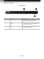
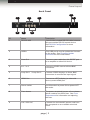
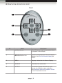
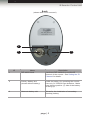
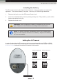
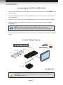
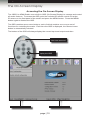
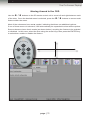
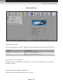
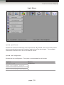
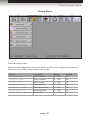
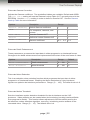
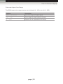
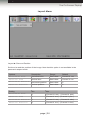
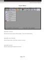
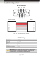
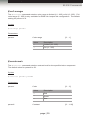
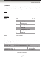
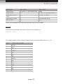
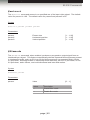
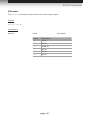
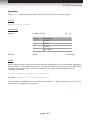
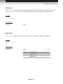
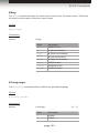
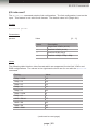
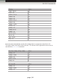
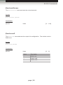
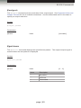
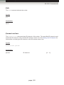
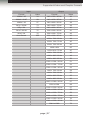
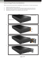
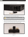
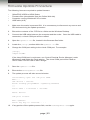
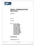
Audio
3GSDI
to
HDMI
3GSDI Embedder
Scaler
GEF-3GSDI-2-HDS
User Manual
Release A6
3GSDI to HDMI Scaler
Important Safety Instructions
GENERAL SAFETY INFORMATION
1.
Read these instructions.
2.
Keep these instructions.
3.
Heed all warnings.
4.
Follow all instructions.
5.
Do not use this product near water.
6.
Clean only with a dry cloth.
7.
Do not block any ventilation openings. Install in accordance with the manufacturer’s
instructions.
8.
Do not install or place this product near any heat sources such as radiators, heat
registers, stoves, or other apparatus (including amplifiers) that produce heat.
9.
Do not defeat the safety purpose of the polarized or grounding-type plug. A polarized
plug has two blades with one wider than the other. A grounding type plug has two
blades and a third grounding prong. The wide blade or the third prong are provided for
your safety. If the provided plug does not fit into your outlet, consult an electrician for
replacement of the obsolete outlet.
10. Protect the power cord from being walked on or pinched particularly at plugs,
convenience receptacles, and the point where they exit from the apparatus.
11. Only use attachments/accessories specified by the manufacturer.
12. To reduce the risk of electric shock and/or damage to this product, never handle or
touch this unit or power cord if your hands are wet or damp. Do not expose this
product to rain or moisture.
13. Unplug this apparatus during lightning storms or when unused for long periods of time.
14. Refer all servicing to qualified service personnel. Servicing is required when the
apparatus has been damaged in any way, such as power-supply cord or plug is
damaged, liquid has been spilled or objects have fallen into the apparatus,
the apparatus has been exposed to rain or moisture, does not operate normally,
or has been dropped.
15. Batteries that may be included with this product and/or accessories should never be
exposed to open flame or excessive heat. Always dispose of used batteries
according to the instructions.
RACK MOUNT SAFETY INFORMATION
1.
Maximum recommended ambient temperature: 40 ˚C (104 ˚F).
2.
Increase the air flow as needed to maintain the recommended temperature
inside the rack.
3.
Do not exceed maximum weight loads for the rack. Install heavier equipment in the
lower part of the rack to maintain stability.
ii
3GSDI to HDMI Scaler
Warranty Information
Gefen warrants the equipment it manufactures to be free from defects in material and
workmanship.
If equipment fails because of such defects and Gefen is notified within two (2) years from
the date of shipment, Gefen will, at its option, repair or replace the equipment, provided
that the equipment has not been subjected to mechanical, electrical, or other abuse or
modifications. Equipment that fails under conditions other than those covered will be
repaired at the current price of parts and labor in effect at the time of repair. Such repairs
are warranted for ninety (90) days from the day of reshipment to the Buyer.
This warranty is in lieu of all other warranties expressed or implied, including without
limitation, any implied warranty or merchantability or fitness for any particular purpose, all of
which are expressly disclaimed.
1.
Proof of sale may be required in order to claim warranty.
2.
Customers outside the US are responsible for shipping charges to and from Gefen.
3.
Copper cables are limited to a 30 day warranty and cables must be in their original
condition.
The information in this manual has been carefully checked and is believed to be accurate.
However, Gefen assumes no responsibility for any inaccuracies that may be contained
in this manual. In no event will Gefen be liable for direct, indirect, special, incidental, or
consequential damages resulting from any defect or omission in this manual, even if
advised of the possibility of such damages. The technical information contained herein
regarding the features and specifications is subject to change without notice.
For the latest warranty coverage information, refer to the Warranty and Return Policy under
the Support section of the Gefen Web site at www.gefen.com.
PRODUCT REGISTRATION
Please register your product online by visiting the Register Product page under the
Support section of the Gefen Web site.
iii
3GSDI to HDMI Scaler
Contacting Gefen Technical Support
Gefen, LLC
c/o Customer Service
20600 Nordhoff St.
Chatsworth, CA 91311
Telephone:
(818) 772-9100
(800) 545-6900
Fax:
(818) 772-9120
Email:
[email protected]
Visit us on the Web:
www.gefenpro.com
Technical Support Hours:
8:00 AM to 5:00 PM Monday - Friday, Pacific Time
For 24 / 7 support, see the back of the product for the
support number
3GSDI to HDMI Scaler is a trademark of Gefen, LLC.
Important Notice
Gefen, LLC reserves the right to make changes in the hardware, packaging, and any
accompanying documentation without prior written notice.
HDMI, the HDMI logo, and High-Definition Multimedia Interface are trademarks or
registered trademarks of HDMI Licensing in the United States and other countries.
© 2013 Gefen, LLC. All Rights Reserved.
All trademarks are the property of their respective owners.
iv
3GSDI to
Audio
HDMI
Embedder
Scaler
Operating Notes
•
The built-in On-Screen Display (OSD) provides convenient operation of the Scaler.
The supplied IR Remote control operates the OSD.
•
The IR Remote Control IR channel must be identical to that of the Scaler.
•
The 3GSDI to HD Scaler supports many input and output resolutions. For a complete
list of supported formats, see Supported Video and Graphic Formats.
•
Supports SMPTE standards 259M, 292M, SMPTE 274M, SMPTE 296M,
ITU-R BT.656 and ITU-R BT.601. Handles 3G-SDI SMPTE 425-A and 425-B / formats
1080P 50/59.94/60.
•
Supports HDMI 1.3 with 225 MHz Video Bandwidth, 10-bit Deep Color
(RGB & YCbCr 4:4:4 only), and up to 8 channels of converted SDI audio embedded
into HDMI.
•
Internal software (firmware) may be upgraded via the built-in Serial or USB ports.
The included DB-9 cable is provided for this purpose. Note that software updates
performed on the USB port will be quicker due to its higher data transfer rate.
v
3GSDI to HDMI Scaler
Features and Packing List
Features
•
Maximum image output resolution supported: 2048 x 1080p (2K)
•
Pattern generation of color bars, and cross-hatch patterns
•
10-bit Deep Color support at when using YCbCr 4:4:4 or RGB 4:4:4
output color spaces
•
Four aspect ratio modes (Full Screen, Panoramic, Letter/Pillar Box, Extract/Crop)
•
Film Mode (produces a progressively scanned output image from an interlaced
scanned input image accounting for cadence (e.g. 3:2 / 2:2 pull-down)
•
Configuration of clean aperture size and position
•
SDI audio channel selection for audio output
•
Fully integrated sprite-based Menu System
•
Supports 8-Channel PCM audio and Dolby® Digital / DTS® AC3-encoded audio
•
Custom frame rate and/or video timings on output
•
Digital audio output (S/PDIF Coax)
•
RS-232 port for automation
•
Rack-mountable
®
1080P
Packing List
The 3GSDI to HDMI Scaler ships with the items listed below. If any of these items are not
present in your box when you first open it, immediately contact your dealer or Gefen.
•
•
•
•
•
1 x 3GSDI to HDMI Scaler
1 x IR remote contol unit
1 x AC power cord
1 x Set of rack ears
1 x Quick-Start Guide
vi
3GSDI to
Audio
HDMI
Embedder
Scaler
Table of Contents
01
Getting Started
Panel Layout.......................................................................................................... 2
Front Panel..................................................................................................... 2
Back Panel..................................................................................................... 3
IR Remote Control Unit.......................................................................................... 4
Front............................................................................................................... 4
Back............................................................................................................... 5
Installing the Battery....................................................................................... 6
Setting the IR Channel................................................................................... 6
Installation.............................................................................................................. 7
Connecting the 3GSDI to HDMI Scaler.......................................................... 7
Sample Wiring Diagram................................................................................. 7
02
Operating the 3GSDI to HDMI Scaler
The On-Screen Display........................................................................................ 10
Accessing the On-Screen Display................................................................ 10
Moving Around in the OSD.......................................................................... 11
General Menu.............................................................................................. 12
Patterns Menu.............................................................................................. 13
Output Menu................................................................................................ 14
Input Menu................................................................................................... 18
Picture Menu................................................................................................ 21
Layout Menu................................................................................................ 24
Aspect Menu................................................................................................ 25
03
Advanced Operation
RS-232 Configuration........................................................................................... 30
RS-232 Interface.......................................................................................... 30
RS-232 Settings........................................................................................... 30
RS-232 Commands.............................................................................................. 31
04Appendix
Supported Video and Graphic Formats................................................................ 56
Uploading an EDID.............................................................................................. 58
Gamma Look-up Table......................................................................................... 59
Mounting Plate Installation................................................................................... 60
Fuse Replacement............................................................................................... 61
Firmware Update Procedure................................................................................ 63
Specifications....................................................................................................... 64
viii
3GSDItoHDMI
Scaler
01 Getting Started
Panel Layout.......................................................................................................... 2
Front Panel..................................................................................................... 2
Back Panel..................................................................................................... 3
IR Remote Control Unit.......................................................................................... 4
Front............................................................................................................... 4
Back............................................................................................................... 5
Installing the Battery....................................................................................... 6
Setting the IR Channel................................................................................... 6
Installation.............................................................................................................. 7
Connecting the 3GSDI to HDMI Scaler.......................................................... 7
Sample Wiring Diagram................................................................................. 7
Getting Started
Panel Layout
Front Panel
1
3
2
ID
Name
Description
1
IR
This IR sensor receives signals from the IR
remote control unit (not included).
2
3GSDI
This LED will glow blue when 3GSDI signals
are detected on the output.
3
Power
This LED indicator will glow bright red when
the scaler is powered ON.
page | 2
Getting Started
Panel Layout
Back Panel
8
1
2
4
3
6
9
5
7
ID
Name
Description
1
RS-232-422
Connect the included RS-232 cable between
this port and the RS-232 control device.
See RS-232 Configuration for more
information.
2
USB In
This USB port is used to update the firmware
on the scaler. See Firmware Update
Procedure for more information.
3
Coax Out
Connect a coax cable from this S/PDIF port
to an amplifier or other A/V device.
4
In 1 / In 2
Connect a 3GSDI source to these BNC
connectors.
5
Loop Out 1 / Loop Out 2
Connect 3GSDI displays to these BNC
connectors to monitor the input signal.
6
HDMI Out
Connect an HDTV display (or other sink
device) to this HDMI port.
7
Power switch
Use this switch to power ON or power-OFF
the scaler.
8
Fuse drawer
The power receptacle houses a fuse drawer
which contains one 250V fuse. See Fuse
Replacement for information on replacing
the fuse.
9
110 / 220V AC
Connect the included AC power cord from
this receptacle to an available electrical
outlet.
page | 3
Getting Started
IR Remote Control Unit
Front
1
2
3
5
4
ID
Name
Description
1
Activity indicator
This LED glows bright orange when a key
is pressed on the remote.
2
A/S/D/W/ENTER
Used to control features in the On-Screen
Display. See The On-Screen Display for
details.
3
MENU
Displays / hides the On-Screen Display
4
SOURCE
This button has no function.
5
OUTPUT
Consecutively press this button to cycle
through the available output resolutions.
See Supported Video and Graphic Formats
for a list of available formats.
page | 4
Getting Started
IR Remote Control Unit
Back
(shown with cover removed)
1
2
ID
3
Name
Description
1
DIP switch bank
Use these DIP switches to set the IR
channel of the remote. See Setting the IR
Channel for details.
2
Primary battery slot
(shown without battery)
Holds the battery for operating the remote.
Use only 3V CR2032-type batteries. Make
sure that the positive (+) side of the battery
is facing up.
3
Alternate battery slot
Allows for the installation of secondary
(backup) battery.
page | 5
Getting Started
IR Remote Control Unit
Installing the Battery
The IR remote control unit ships with two batteries. Only one battery is required for
operation. The second battery is a spare. Use only 3V CR2032-type batteries.
1.
Remove the back cover the IR Remote Control unit.
2.
Insert the included battery into the primary battery slot. The positive (+) side of the
battery should be facing up.
3.
Replace the back cover.
WARNING: Risk of explosion if battery is replaced by an incorrect
type. Dispose of used batteries according to the instructions.
NOTE: An Activity Indicator that flashes quickly while holding down
any one of the buttons indicates a low battery. Replace the battery
as soon as possible.
Setting the IR Channel
In order for the included IR remote control to communicate with the 3GSDI to HDMI
Scaler, the IR remote control must be set to the same channel as the scaler. Use the
#remotechan command to set the IR channel of the scaler.
Channel 0 (default):
Remote Channel 1:
ON
1
2
Remote Channel 2:
ON
1
Remote Channel 3:
ON
1
DIP switches
page | 6
2
2
ON
1
2
Getting Started
Installation
Connecting the 3GSDI to HDMI Scaler
1.
Use the included locking HDMI cable to connect a Hi-Def source to the HDMI In port
on the scaler.
2.
Connect a BNC-type cable from the Ref In connector, on the scaler, to an external
clock reference.
3.
Connect a coax cable from the Coax Out connector to an external audio amplifier.
4.
Connect a BNC-type cable from the Out A / Out B connector(s) to the 3GSDI
destination.
NOTE: In order to output dual link 1080p Full HD, when using
HD-SDI, both Out A and Out B must be connected to the destination.
5.
Connect the included AC power cord from the power supply to an available electrical
outlet.
Sample Wiring Diagram
SDI CABLE
HDMI CABLE
3G-SDI
Loop Output
COAX AUDIO CABLE
3G-SDI
Loop Output
3G-SDI Source
3G-SDI Source
Scaler
HD Display
Audio Receiver
GEF-3GSDI-2-HDS
WARNING: This product should always be connected to a grounded
electrical AC outlet.
page | 7
3GSDItoHDMI
Scaler
02 Operating the
3GSDI to HDMI Scaler
The On-Screen Display........................................................................................ 10
Accessing the On-Screen Display................................................................ 10
Moving Around in the OSD.......................................................................... 11
General Menu.............................................................................................. 12
Patterns Menu.............................................................................................. 13
Output Menu................................................................................................ 14
Input Menu................................................................................................... 18
Picture Menu................................................................................................ 21
Layout Menu................................................................................................ 24
Aspect Menu................................................................................................ 25
Using the 3GSDI to HDMI Scaler
The On-Screen Display
Accessing the On-Screen Display
The 3GSDI to HDMI Scaler uses a built-in OSD (On-Screen Display) to manage and control
all scaler features. To access the OSD, point the included IR remote control unit at the
IR sensor on the front panel of the scaler and press the MENU button. Press the MENU
button again to dismiss the OSD.
The OSD contains seven menu buttons, each of which contains one or more set of
functions for controlling the scaler. Each time the OSD is displayed, the General menu
button is automatically selected.
The bottom of the OSD will always display the current input and output resolution.
LED indicates a
button was pressed
Press MENU to
display the OSD
Current input resoltuion
Current output resolution
page | 10
Using the 3GSDI to HDMI Scaler
The On-Screen Display
Moving Around in the OSD
Use the A
/ D buttons on the IR remote control unit to move left and right between each
W buttons to access each
of the tabs. Once the desired menu is selected, press the S /
feature within the menu.
Most of the submenus have an ► symbol, indicating that there are additional options.
If one of these menus is selected, it will automatically be expanded to show all the options.
Some submenus have check marks (as shown below), requiring the feature to be enabled
or disabled. In this case, select the item using the arrow keys, then press the ENTER key
to select then enable or disable the feature.
page | 11
Using the 3GSDI to HDMI Scaler
The On-Screen Display
General Menu
General ► Language
Sets the language of the OSD. Select the desired language and press the ENTER key.
Options
Description
English (default)
Sets the OSD in English
French
Localizes the OSD in French
General ► Save Configuration
Saves the current configuration of the scaler. The current configuration of the scaler is
saved in memory.
General ► Restore default configuration
Restores the factory-default settings of the scaler.
page | 12
Using the 3GSDI to HDMI Scaler
The On-Screen Display
Patterns Menu
Patterns ► Color Bars
Produces a color bar pattern, similar to a standard SMPTE bar pattern used for color
calibration. After selecting this option, press the ENTER button to enable / disable the
color bar pattern. When the color bar pattern is enabled, no video output will be displayed.
Patterns ► Cross Hatch
Produces a color bar pattern, similar to a standard SMPTE bar pattern used for color
calibration. After selecting this option, press the ENTER button to enable / disable the
color bar pattern. When the color bar pattern is enabled, no video output will be displayed.
page | 13
Using the 3GSDI to HDMI Scaler
The On-Screen Display
Output Menu
Output ► Available Formats
If this option is set to Monitor Supported, then only output resolutions found in the EDID
of the display can be selected. If set to All, then any of the available output resolutions,
provided by the scaler, can be selected.
Options
Description
Default
All
All output formats available
All
Monitor Supported
Only monitor-supported
resolutions are selectable
Output ► Video Output Format
Selects the video output resolution. See Supported Video and Graphic Formats for a list of
available output formats.
page | 14
Using the 3GSDI to HDMI Scaler
The On-Screen Display
Output ► Graphic Output Format
Selects the graphic (VESA) output resolution. See Supported Video and Graphic Formats
for a list of available output formats.
Output ► Custom Output Format
This option customized the output format.
Options
Description
HTotal
Total Horizonal Lines
HActive
Active Horizontal Lines
HSync Back Porch
Horizontal Back Porch
HSync Width
Horizontal Sync Width
VTotal
Total Vertical Lines
VActive
Active Vertical Lines
VSync Back Porch
Vertical Back Porch
VSync Width
Vertical Sync Width
Refresh Rate
Refresh (Frame) Rate
The following table lists the formulas for obtaining the minimum and maximum values for
each settings. The minimum and maximum values depend upon the current output format.
Options
Minimum Value
Maximum Value
HTotal
HActive - HSync Back
Porch
3500
HActive
1
HTotal - HSync Back Porch
HSync Back Porch
1
HTotal - HActive
HSync Width
1
HSync Back Porch
VTotal
VActive + VSync Back
Porch
3500
VActive
1
VTotal - VSync Back Porch*
VSync Back Porch
1
VTotal - VActive
VSync Width
1
VSync Back Porch
Refresh Rate
0
13
*If the maximum VActive value reaches 2048, then the maximum value is set to 2048.
(continued on next page)
page | 15
Using the 3GSDI to HDMI Scaler
The On-Screen Display
The following table lists the Refresh Rates and their corresponding values (0 - 13).
Value
Refresh (frame) rate
Value
Refresh (frame) rate
0
23.98
7
59.94
1
24
8
60
2
25
9
65
3
29.97
10
70
4
30
11
75
5
48
12
80
50
13
85
6
Output ► Link Configuration
Selects the output link configuration with respect to color space.
Options
Default
RGB 4:4:4
RGB 4:4:4
YCbCr 4:4:4
YCbCr 4:2:2
Output ► Frame Rate
Selects the frame rate of the output signal.
Options
Default
Default
60 Hz
48 Hz
50 Hz
59.95 Hz
60 Hz
75 Hz
85 Hz
page | 16
Using the 3GSDI to HDMI Scaler
The On-Screen Display
Output ► Deep Color
Sets the deep color mode. When set to Automatic, the deep color is programmed
according to the EDID of the sink device.
Options
Description
Default
Automatic
EDID-specified color
Automatic
Force 8 bits
Forces 8-bit color
page | 17
Using the 3GSDI to HDMI Scaler
The On-Screen Display
Input Menu
Input ► Input Format
Selects the resolution and timing of the input format. By default, this is set to Auto Detect
which automatically senses the resolution and timing of the input signal. The available
resolutions under this menu are in SD and HD format.
Input ► Link Configuration
Selects the link configuration. This option is not available for all formats.
Options
Default
Single Link
Single Link
Dual Link YCbCr (4:4:4)
Dual Link RGB (4:4:4)
Dual Link 1080p/576p/480p
page | 18
Using the 3GSDI to HDMI Scaler
The On-Screen Display
Input ► Clean Aperture
Allows adjustment of the input signal position. The clean aperture parameters allow an
area within the production aperture to be defined. The minimum clean aperture size is
0 pixels by 0 lines. If the Non-Standard Sync option is enabled, then the input is set to
DFP sync.
Options
Description
Range
Default
Horizontal Size
Sets Horizontal size
1 ... 100
100
Vertical Size
Sets Vertical size
1 ... 100
100
Horizontal Position
Sets Horizontal position
1 ... 100
50
Vertical Position
Sets Vertical position
1 ... 100
50
Input ► Film Mode
When enabled, produces a progressive output signal from an interlaced input signal. This
feature automatically detects repeated field sequences present in interlaced signals, such
as 50 Hz or 60 Hz field sequences (no repeated fields), 60 Hz 3:2 pull-down, including
broken or edited sequence detection, 60 Hz 2:2: pull-down, 50 Hz 2:2 pull-down, static
frames, and multi-directional and inter-field motion.
Options
Description
Enable
Enables film mode
Disable (default)
Disables film mode
Input ► Audio
Sets the number of audio channels. Range: [1 ... 8]. The default value is 1.
(continued on next page)
page | 19
Using the 3GSDI to HDMI Scaler
The On-Screen Display
Input ► Remote Channel
This option changes the IR channel to between 0 and 3. When the remote channel
of the Scaler is changed, the DIP switches on the IR remote must be changed to the
corresponding IR channel in order to operate the Scaler. See Setting the IR Channel
for details on how to set the IR channel on the IR remote control unit.
Options
Description
0 (default)
IR channel 0
1
IR channel 1
2
IR channel 2
3
IR channel 3
page | 20
Using the 3GSDI to HDMI Scaler
The On-Screen Display
Picture Menu
Picture ► Image Colour
Allows individual adjustment of the Red, Green, and Blue color components, brightness,
and black level (RGB/Y Output Offset) of the image.
Options
Description
Range
Default
Contrast Red
Red contrast
0 ... 255
50
Contrast Green
Green contrast
0 ... 255
50
Contrast Blue
Blue contrast
0 ... 255
50
Brightness Red
Red brightness
0 ... 255
50
Brightness Green
Green brightness
0 ... 255
50
Brightness Blue
Blue brightness
0 ... 255
50
RGB/Y Output Offset
Black level
0 ... 1023
0
page | 21
Using the 3GSDI to HDMI Scaler
The On-Screen Display
Picture ► Gamma Correction
Adjusts the Gamma coefficient. Two predefined tables are available: Default and sRGB.
The User Table setting will use the Gamma Lookup Table (LUT) currently stored in the
EEPROM. Use the Custom setting in order to define a Gamma LUT. See the Gamma
Look-up Table for more information.
Options
Description
Range
Default (default)
Default Gamma coefficient
-
-
sRGB
For computers, cameras, and
printers
-
-
User Table
Uses the Gamma LUT
-
-
Custom
Defines a custom Gamma LUT
-
-
Gamma Coefficient
Gamma coefficient
0.3 ... 3.0
1.0
Picture ► Detail Enhancement
These parameters processes the input data in either progressive or interlaced format.
Changes to the detail enhancement are implemented at the start of the next frame of video.
Options
Description
Range
Default
Detail Enhancement
Detail enhancement
0 ... 100
0
Noise Threshold
Noise threshold
0 ... 100
0
Picture ► Noise Reduction
This is an adaptive noise reduction function which processes the input data in either
progressive or interlaced format. Enabling the Noise Reduction to noisy interlaced
signals can optimize de-interlacer performance. Range: [0 ... 100]. The default value is 0.
Picture ► Motion Threshold
Sets the intraframe motion detection threshold for the de-interlacer on the VXP
processor. Video artifacts can be created when de-interlacing (creating interlaced fields
from progressive fields). This function allows adjustment of the threshold used by the
de-interlacer motion detection algorithm, removing / minimizing motion artifacts in the
converted video. Range: [0 ... 15]. The default value is 4.
page | 22
Using the 3GSDI to HDMI Scaler
The On-Screen Display
Picture ► Output Color Range
The RGB output color range may be set to limited (16 - 235) or to full (0 - 255).
Options
Description
Auto (default)
Use color range of output signal
16 - 235
Color range of output signal is limited
0 - 255
Output color is expanded to full-range
page | 23
Using the 3GSDI to HDMI Scaler
The On-Screen Display
Layout Menu
Layout ► Size and Position
Set the size and the position of the image. Note that this option is not available in the
panoramic aspect mode.
Options
Description
Range
Default
Horizontal Size
Horizontal size
See below
Current H. res.
Vertical Size
Vertical size
See below
Current V. res.
Horizontal Position
Horizontal position
See below
0
Vertical Position
Vertical position
See below
0
Setting
Min
Max
Horizontal Size
1
(Current H. res.) - (Current H. pos.)
Vertical Size
1
(Current V. res.) - (Current V. pos.)
Horizontal Position
0
(Current H. res.) - (Current H. size)
Vertical Position
0
(Current V. res.) - (Current V. size)
page | 24
Using the 3GSDI to HDMI Scaler
The On-Screen Display
Aspect Menu
Aspect ► Full Screen
Stretches the output signal to fill the display. This is the default setting.
Aspect ► Letter / Pillar Box
Sets the aspect ratio to fit a letter or pillar box format.
Aspect ► Panoramic
Sets the output signal to panoramic format.
page | 25
Using the 3GSDI to HDMI Scaler
The On-Screen Display
Aspect ► Extract
This a function allows the Scaler to zoom in on a subset of the input video signal.
This feature allow you to zoom on one selected section of the input picture.
Options
Description
Range
Default
Extract Size
Size (%)
0 ... 100
100
Horizontal Position
Horizontal position
0 ... 100
50
Vertical Position
Vertical position
0 ... 100
50
Aspect ► Through
This function defines a sub-window that is always centered on the screen. The position is
the relative position of the window within the full picture. This feature allows you to display
one selected section of the input picture without modifying its size.
Options
Description
Range
Default
Horizontal Size
Horizontal size
1 ... 100
-
Vertical Size
Vertical size
1 ... 100
-
Horizontal Position
Horizontal position
0 ... 100
-
Vertical Position
Vertical position
0 ... 100
-
NOTE: When changing the input format, the scaler will try and apply
the current settings to the new input format. If this is not possible
(e.g. the value is beyond the zoom limit), then the default value
(100% size) will be used.
page | 26
3GSDItoHDMI
Scaler
03 Advanced Operation
RS-232 Configuration........................................................................................... 30
RS-232 Interface.......................................................................................... 30
RS-232 Settings........................................................................................... 30
RS-232 Commands.............................................................................................. 31
Advanced Operation
RS-232 Configuration
RS-232 Interface
5 4
3
2 1
DE-9
6 7
8
9
DA-15
RS-232 Controller
Scaler
DCD
1
1
DCD
RXD
2
2
RXD
TXD
3
3
TXD
DTR
4
4
DTR
GND
5
5
DSR
6
6
RTS
7
7
CTS
8
8
CTS
R1
9
9
R1
Only TXD, RXD, and GND pins are used.
DB-25
GND
DSR
RTS
DC-37
RS-232 Settings
Description
Setting
Baud rate
115200
Data bits
8
Parity
None
Stop bits
1
Hardware flow control
None
DD-50
IMPORTANT: When sending RS-232 commands, a carriage return
must be included at the end of the command. A space must be
included between the command and each parameter.
page | 30
Advanced Operation
RS-232 Commands
Command
Description
#aspect
Sets the aspect ratio of the output signal
#audio
Changes the audio channel
#autolock
Enables / disables automatic Genlock
#blacklev
Sets the black level of the output signal
#bright
Sets the brightness of the specified color component
#cleanaper
Defines an area within the production aperture
#colrange
Sets the color range to limited or full
#contrast
Sets the contrast of the specified color component
#custom
Modifies the output format
#deepcolor
Sets the deep color mode
#devtype
Returns the device type that is connected
#deversion
Displays the current hardware and software version
#enhance
Sets the enhancement detail of the output signal
#extract
Zooms-in on specified are of the input video signal
#filmmode
Enables / disables film mode
#frame
Set the frame rate of the output signal
#gamma
Sets the gamma correction mode
#input
Sets the input timing for the source signal
#insel
Sets the input channel
#key
Used to emulate the IR remote control unit using RS-232
#language
Set the OSD to the specified language
#linkconf
Sets the link configuration
#motionthres
Sets the intraframe motion detection threshold
#noisereduc
Sets the noise reduction value
#noisethres
Sets the noise threshold value
#outconf
Sets the output link configuration
#outconf
Sets the output resolution of the output signal
#pattern
Displays the specified test pattern
#rb
Reboots the scaler
#remotechan
Sets the IR channel of the scaler
#restore
Resets the scaler to factory-default settings
#save
Saves all current settings to the PROM
#sizepos
Sets the size and position of the output signal
#through
Defines an area of the output image with cropping
#version
Displays the current firmware, kernel, and configuration
page | 31
Advanced Operation
RS-232 Commands
#aspect
The #aspect command sets the aspect ratio of the output signal.
Syntax:
#aspect param1
Parameters:
param1
Aspect ratio
Value
Description
1
Full screen
2
Letter / Pillar box
3
Panoramic
4
Extract
5
Through
[1 ... 5]
Notes:
If the Extract or Through mode is selected, the default values are used. To modify the
parameters for Extract or Through mode refer to these commands in this manual.
#audio
The #audio command changes the audio channel. The default setting for param1 is 1.
Syntax:
#audio param1
Parameters:
param1
Audio channel
page | 32
[1 ... 8]
Advanced Operation
RS-232 Commands
#autolock
The #autolock command enables or disables the Genlock mode. The default setting for
param1 is 0.
Syntax:
#autolock param1
Parameters:
param1
Aspect ratio
Value
Description
0
Disable
1
Enable
[0 ... 1]
#blacklev
The #blacklev command sets the black level of the output signal. This is the equivalent
of adjusting the RGB/Y Output Offset using the OSD. Refer to the Picture Menu for more
information. The default setting is 0.
Syntax:
#blacklev param1
Parameters:
param1
Level
page | 33
[0 ... 1023]
Advanced Operation
RS-232 Commands
#bright
The #bright command sets the color brightness for the specified color component.
The default setting for param2 is 50.
Syntax:
#bright param1 param2
Parameters:
param1
param2
Color
Value
Description
0
Red
1
Green
2
Blue
Color level
[0 ... 2]
[0 ... 100]
#cleanaper
The #cleanaper command allows adjustment of the input signal position. Each parameter
allows an area within the production aperture to be defined. The minimum clean aperture
size is 0 pixels by 0 lines.
Syntax:
#cleanaper param1 param2 param3 param4
Parameters:
param1
param2
param3
param4
Horizontal size (default = 100)
Vertical size (default = 100)
Horizontal position (default = 50)
Vertical position (default = 50)
page | 34
[1 ... 100]
[1 ... 100]
[1 ... 100]
[1 ... 100]
Advanced Operation
RS-232 Commands
#colrange
The #colrange command sets the color range to limited (16 - 235) or full (0 - 255). Full
color range (0 - 255) is only available for RGB 4:4:4 output link configuration. The default
setting for param1 is 0.
Syntax:
#colrange param1
Parameters:
param1
Color range
Value
Description
0
Limited (16 - 235)
1
Full (0 - 255)
[0 ... 1]
#contrast
The #contrast command sets the contrast level for the specified color component.
The default value for param2 is 50.
Syntax:
#contrast param1 param2
Parameters:
param1
param2
Color
Value
Description
0
Red
1
Green
2
Blue
Contrast
page | 35
[0 ... 2]
[0 ... 100]
Advanced Operation
RS-232 Commands
#custom
The #custom command modifies the output format. The minimum and maximum values
depend upon the current output format. The attribute is specified by param1. Use param2
to set the value of the attribute, specified by param1.
Syntax:
#custom param1 param2
Parameters:
Value
param1
Value
Description
0
Horizontal Total
1
Horizontal Active
2
Horizontal Back Porch
3
Horizontal Sync Width
4
Vertical Total
5
Vertical Active
6
Vertical Sync Back Porch
7
Vertical Sync Width
8
Refresh Rate
[0 ... 8]
param2Value for param1
Notes:
Use the following table to calculate the minimum and maximum values for each attribute,
when specifying param2.
Description
Min. Value
Max. Value
Horizontal Total
H. Active + H. Sync Back Porch
3500
Horizontal Active
1
H. Total - H. Sync Back Porch
Horizontal Back Porch
1
H. Total - H. Active
Horizontal Sync Width
1
H. Sync Back Porch
(continued on next page)
page | 36
Advanced Operation
RS-232 Commands
Description
Min. Value
Max. Value
Vertical Total
V. Active + V. Sync Back Porch
3500
Vertical Active
1
V. Total - V. Sync Back Porch*
Vertical Sync Back
Porch
1
V. Total - V. Active
Vertical Sync Width
1
V. Sync Back Porch
Refresh Rate
0
13
*If this value reaches 2048, then the maximum value is set to 2048.
Example:
In the following example, the Vertical Total is set to 2000 lines:
#custom 4 2000
The following table lists the Refresh Rates and their corresponding values (0 - 13).
Value
Refresh (frame) rate
0
23.98
1
24
2
25
3
29.97
4
30
5
48
6
50
7
59.94
8
60
9
65
10
70
11
75
12
80
13
85
page | 37
Advanced Operation
RS-232 Commands
#deepcolor
The #deepcolor command sets the deep color mode. The default value for param1 is
Automatic (Auto).
Syntax:
#deepcolor param1
Parameters:
param1
Value
Value
Description
0
Auto
1
Force 8-bit
[0 ... 1]
#devtype
The #devtype command displays the type of device that is connected. This command
is used by the update program, when updating the firmware, but can be executed for any
reason.
Syntax:
#devtype
Parameters:
None
Example:
#devtype
#DEVTYPE HDMITO3GSDI
page | 38
Advanced Operation
RS-232 Commands
#deversion
The #deversion command displays the current hardware (card) and software version in
the format: CARD_VERSION?SOFTWARE_VERSION.
Syntax:
#deversion
Parameters:
None
Example:
#deversion
#DEVERSION 1?3.2.6
#enhance
The #enhance command improves the detail of the output signal. The default value for
param1 is 0.
Syntax:
#enhance param1
Parameters:
param1
Level
page | 39
[0 ... 100]
Advanced Operation
RS-232 Commands
#extract
The #extract command zooms-in on specified are of the input video signal. The default
value for param1 is 100. The default value for param2 and param3 is 50.
Syntax:
#extract param1 param2 param3
Parameters:
param1
param2
param3
Extract size
Horizontal position
Vertical position
[1 ... 100]
[1 ... 100]
[1 ... 100]
#filmmode
The #filmmode command, when enabled, produces a progressive output signal from an
interlaced input signal. This feature automatically detects repeated field sequences present
in interlaced signals, such as 50 Hz or 60 Hz field sequences (no repeated fields), 60 Hz
3:2 pull-down, including broken or edited sequence detection, 60 Hz 2:2: pull-down, 50 Hz
2:2 pull-down, static frames, and multi-directional and inter-field motion.
Syntax:
#filmmode param1
Parameters:
param1
Value
Value
Description
0
Disable film mode
1
Enable film mode
page | 40
[0 ... 1]
Advanced Operation
RS-232 Commands
#frame
The #frame command sets the frame rate of the output signal.
Syntax:
#frame param1
Parameters:
param1
Value
Value
Description
5
48 Hz
6
50 Hz
7
59.94 Hz
8
60 Hz
11
75 Hz
13
85 Hz
page | 41
[see table]
Advanced Operation
RS-232 Commands
#gamma
The #gamma command sets the gamma correction mode of the output signal.
Syntax:
#gamma param1 param2
Parameters:
param1
param2
Gamma setting
Value
Description
0
Default
1
sRGB
2
Custom
3
User table
Mode
[0 ... 3]
[see below]
Notes:
If the Custom mode is used, then set the gamma coefficient value in the second parameter.
If User Table is used, then set param2 = 1 to use the table currently saved in the EEPROM.
To write a new gamma LUT (Look-Up Table) file, you must use the updater with the
following command:
updater %comport% gamma [filename].csv
Example: updater com1 gamma mygamma.csv
If the Default or sRGB mode is used, then set param2 = 0. See the Gamma Look-up Table
for details on the gamma LUT format.
page | 42
Advanced Operation
RS-232 Commands
#input
The #input command sets the input timing for the source signal. See Supported Video
and Graphic Formats for a list of available input formats and their associated values.
Syntax:
#input param1
Parameters:
param1
Value
#insel
The #insel command sets the input channel. The default setting is Channel A.
Syntax:
#insel param1
Parameters:
param1
Value
Value
Description
1
Channel A
2
Channel B
page | 43
[1 ... 2]
Advanced Operation
RS-232 Commands
#key
The #key command emulates the same control used on the IR remote control. Either the
full word or the first letter of the word can be used.
Syntax:
#key param1
Parameters:
param1
String
Value
Description
menu
MENU button
up
W (Up arrow button)
down
S (Down arrow button)
left
A (Left arrow button)
right
D (Right arrow button)
enter
ENTER button
source
SOURCE button
output
OUTPUT button
#language
The #language command sets the OSD to the specified language.
Syntax:
#language param1
Parameters:
param1
Language
Value
Description
0
English
1
French
page | 44
[0 ... 1]
Advanced Operation
RS-232 Commands
#linkconf
The #linkconf command sets the link configuration. The link configuration is set on the
input. This feature is not valid for all formats. The default valus is 0 (Single link).
Syntax:
#linkconf param1
Parameters:
param1
Value
[0 ... 3]
Value
Description
0
Single link YCbCr (4:2:2)
1
Dual link YCbCr (4:4:4)
2
Dual link RGB (4:4:4)
3
Dual link 1080p / 576p / 480p
Notes:
The following table lists the video formats which are supported for dual link YCbCr and
RGB configurations. The values in the right-hand column are for use with the #outconf
command.
Timing
Value
720p / 23.98
15
720p / 24
14
720p / 25
13
720p / 30
11
720p / 50
10
720p / 59.94
9
720p / 60
8
1035i / 59.94
17
1035i / 60
16
1080i / 50
24
1080i / 50M
25
(continued on next page)
page | 45
Advanced Operation
RS-232 Commands
Timing
Value
1080i / 59.94
23
1080i / 60
22
1080sf / 23.98
35
1080sf / 24
33
1080sf / 25
31
1080sf / 29.97
29
1080sf / 30
27
1080p / 23.98
34
1080p / 24
32
1080p / 25
30
1080p /29.97
28
1080p / 30
26
2K-sf / 23.97
73
2K-sf / 24
74
2Kp / 23.98
75
2Kp / 24
76
Some formats automatically set the link configuration to progressive dual link 4:2:2.
The table, below, lists these video formats. The values in the right-hand column are for
use with the #outconf command.
Dual link 1080p / 576p / 480p
Value
1080p / 60
18
1080p / 59.94
19
1080p / 50
20
480p / 59.94
6
576p / 50
7
3G Level-B
Value
1080p / 60
18
1080p / 59.94
19
1080p / 50
20
page | 46
Advanced Operation
RS-232 Commands
#motionthres
The #motionthres command sets the intraframe motion detection threshold for the
de-interlacer on the VXP processor. Video artifacts can be created when de-interlacing
(creating interlaced fields from progressive fields). This function allows adjustment of the
threshold used by the de-interlacer motion detection algorithm, removing / minimizing
motion artifacts in the converted video. The factory-default setting is 4.
Syntax:
#motionthres param1
Parameters:
param1
Value
[0 ... 15]
#noisereduc
The #noisereduc command sets the noise reduction value.
Syntax:
#noisereduc param1
Parameters:
param1
Value
page | 47
[0 ... 100]
Advanced Operation
RS-232 Commands
#noisethres
The #noisethres command sets the noise threshold.
Syntax:
#noisethres param1
Parameters:
param1
Value
[0 ... 100]
#outconf
The #outconf command sets the output link configuration. The default value is
RGB 4:4:4.
Syntax:
#outconf param1
Parameters:
param1
Value
Value
Description
0
RGB 4:4:4
1
YCbCr 4:4:4
2
YCbCr 4:2:2
page | 48
[0 ... 2]
Advanced Operation
RS-232 Commands
#output
The #output command sets the resolution of the output signal. See Supported Video and
Graphic Formats for list of available resolutions. Use the associated value in the table to
specify an output resolution.
Syntax:
#output param1
Parameters:
param1
Value
[see table]
#pattern
The #pattern command displays the specified test pattern. The original output signal is
masked when the test pattern is displayed.
Syntax:
#pattern param1
Parameters:
param1
Value
Value
Description
0
No pattern
1
Color bar
2
Cross hatch
page | 49
[0 ... 2]
Advanced Operation
RS-232 Commands
#rb
The #rb command reboots the scaler.
Syntax:
#rb
Parameters:
None
#remotechan
The #remotechan command sets IR channel of the scaler. The specified IR channel must
match the IR channel of the included IR remote control unit. See Setting the IR Channel for
instructions on setting the IR channel on the IR remote control unit.
Syntax:
#remotechan param1
Parameters:
param1
IR channel
page | 50
[0 ... 3]
Advanced Operation
RS-232 Commands
#restore
The #restore command resets the 3GSDI to HDMI Scaler to factory-default settings.
Syntax:
#restore
Parameters:
None
#save
The #save command saves all the current parameter settings to the PROM.
These parameters will be reloaded upon the next boot up.
Syntax:
#save
Parameters:
None
page | 51
Advanced Operation
RS-232 Commands
#sizepos
The #sizepos command sets the size and the position of the image. This option is not
available when the Aspect Mode is set to Panoramic.
Syntax:
#sizepos param1 param2 param3 param4
Parameters:
param1
param2
param3
param4
Horizontal size
Vertical size
Horizontal position
Vertical position
[1 ... max]
[1 ... max]
[0 ... max]
[0 ... max]
Notes:
Use the following formulas to calculate the maximum values for each parameter:
param1:
param2:
param3:
param4:
Current horizontal resolution - current horizontal position
Current vertical resolution - current vertical position
Current horizontal resolution - current horizontal size
Current vertical resolution - current vertical size
page | 52
Advanced Operation
RS-232 Commands
#through
The #through command defines a sub-window that is always centered on the screen.
The position of the sub-window is relative to the size and position of the original output
signal.
Syntax:
#through param1 param2 param3 param4
Parameters:
param1
param2
param3
param4
Horizontal size
Vertical size
Horizontal position
Vertical position
[1 ... 100]
[1 ... 100]
[0 ... 100]
[0 ... 100]
#version
The #version command displays the current version of host firmware, Kernel, and the
configuration version.
Syntax:
#version
Parameters:
None
page | 53
3GSDItoHDMI
Scaler
04Appendix
Supported Video and Graphic Formats................................................................ 56
Uploading an EDID.............................................................................................. 58
Gamma Look-up Table......................................................................................... 59
Mounting Plate Installation................................................................................... 60
Fuse Replacement............................................................................................... 61
Firmware Update Procedure................................................................................ 63
Specifications....................................................................................................... 64
Appendix
Supported Video and Graphic Formats
The following table contains all supported video and graphic formats supported by
the 3GSDI to HDMI Scaler. The Value column contains a list of parameters used by
RS-232.
Input
Output
Format
Value
Format
Value
480i
0
480i
0
480p / 59.94 Hz
6
480p / 59.94 Hz
6
576i
1
576
1
576p / 50 Hz
7
576p
7
720p / 23.97 Hz
15
720p / 23.97
15
720p / 24 Hz
14
720p / 24
14
720p / 25
13
720p / 25
13
720p / 29.97
12
720p / 29.97
12
720p / 30
11
720p / 30
11
720p / 50
10
720p / 50
10
720p / 60
8
720p / 60
8
720p / 59.94
9
720p / 59.94
9
1035i / 59.94
64
1035i / 59.94
64
1035i / 50
63
1035i / 50
63
1080i / 50
24
1080i / 50
24
1080i / 50M
25
1080i / 50M
25
1080i / 59.94
23
1080i / 59.94
23
1080i / 60
22
1080i / 60
22
1080p / 23.98
34
1080p / 23.98
34
1080p / 24
32
1080p / 24
32
1080p / 25
30
1080p / 25
30
1080p / 29.97
28
1080p / 29.97
28
1080p / 30
26
1080p / 30
26
1080p / 50
20
1080p / 50
20
1080p / 50M
21
1080p / 50M
21
1080p / 59.94
19
1080p / 59.94
19
1080p / 60
18
1080p / 60
18
1080sf /23.98
35
2K-p / 23.98
75
1080sf / 24
33
2K-p / 24
76
page | 56
Appendix
Supported Video and Graphic Formats
Input
Output
Format
Value
Format
Value
1080sf / 25
31
640 x 350 / 85 Hz
36
1080sf / 29.97
29
640 x 400 / 85 Hz
37
1080sf / 30
27
640 x 480 / 60 Hz
38
2K-p / 23.98
73
640 x 480 / 75 Hz
39
2K-p / 24
74
640 x 480 / 85 Hz
40
2K-sf / 23.98
75
800 x 600 / 60 Hz
41
2K-sf / 24
76
800 x 600 / 75 Hz
42
Auto Detect
255
800 x 600 / 85 Hz
43
1024 x 768 / 60 Hz
44
1024 x 768 / 75 Hz
45
1024 x 768 / 85 Hz
46
1280 x 854
65
1152 x 864 / 75 Hz
47
1280 x 768 / 60 Hz
48
1280 x 960 / 60 Hz
49
1280 x 960 / 85 Hz
50
1280 x 1024 / 60 Hz
51
1280 x 1024 / 75 Hz
52
1280 x 1024 / 85 Hz
53
1360 x 768 / 60 Hz
54
1366 x 768 / 60 Hz
56
1366 x 923 / 50 Hz
55
1440 x 900 / 60 Hz
66
1440 x 1080 / 60 Hz
67
1600 x 1024
68
1600 x 1200 / 60 Hz
57
1600 x 1200 / 65 Hz
58
1600 x 1200 / 70 Hz
59
1600 x 1200 / 75 Hz
69
1680 x 1050 / 60 Hz
70
1920 x 1200 / 60 Hz
71
2048 x 1080
72
page | 57
Appendix
Uploading an EDID
The 3GSDI to HDMI Scaler allows a custom EDID to be uploaded and read by the
display / sink device. Use the instructions below to upload an EDID. The EDID must
be .bin format.
1
Download the 3GSDI-2-HDS firmware file from the Gefen Web site.
2
Extract the contents of the .zip file to the desired directory.
3
Copy the EDID file, to be uploaded, into the same directory as the extracted files.
4
Open the Updater.ini file and locate the [Device Firmware] section.
[Device Firmware]
device1=Device1.bin
device5=Device5.bin
FPGA=3GSDI-2-HDMI-SCALER.bin
Micro=appMain.mot
EDID=EDID.bin
5
Replace the EDID=EDID.bin line with the name of the EDID to be uploaded.
For example:
EDID=Dell_EDID.bin
6
Locate the [Force Update] section and change the values to the following:
[Force Update]
device1=0
device5=0
FPGA=0
Micro=0
EDID=1
7
Run the GefenUpdater.exe file.
page | 58
Appendix
Gamma Look-up Table
The Gamma Look Up Table (LUT) can be programmed using the GefenUpdater.exe
program from the Gefen software package. To do this, following the instructions below:
1
Create the Gamma LUT.
2
Create a standard ASCII text file with the following line:
GefenUpdater GAMMA filename.csv
where filename.csv is the name of the Gamma LUT file.
3
Save the file as UpdateGamma.bat. Make sure that the GefenUpdater.exe file
resides in the same directory (or is in the path) as the UpdateGamma.bat file.
4
Connect a USB cable from the computer to the 3GSDI to HDMI Scaler.
5
Power on the 3GSDI to HDMI Scaler. Once the scaler has powered up, run the
UpdateGamma.bat file.
The LUT is a standard .CSV file. Each line contains Red, Green and Blue values separate
by comma ”,”. A value must be between 0 and 1023. A file must contain 1024 lines:
1023,0,0 1023,0,0
1023,0,0
1023,0,0
1023,0,0
1023,0,0
1023,0,0
…
…
1023,0,0 (Line 1)
(Line 1024)
page | 59
Appendix
Mounting Plate Installation
Rack mount ears are provided for installation of this unit into a 1U rack mount space.
1.
2.
3.
4.
Locate the side screws on the unit.
Remove the front 2 screws that are located closest to the front of the unit.
Using the removed screws, screw the rack mounting bracket into the unit.
Repeat the procedure on the opposite side of the unit.
1
Front of unit
Rear of unit
2
3
4
page | 60
Appendix
Fuse Replacement
The 3GSDI to HDMI Scaler contains a fuse as part of the internal power supply. This fuse
can easily be replaced by using the following steps.
STOP: Before installing modules and prevent the risk of possible
electrical shock, unplug the AC power cord from back of the scaler.
1.
Disconnect the power AC power cord from the IEC connector on the scaler.
2.
Locate the fuse door, between the IEC connect and the power switch, on the back
of the unit.
3.
Use a small flat-head screwdriver to gently pry the locking mechanism, on the fuse
door, from the scaler.
4.
Remove the fuse door.
page | 61
Appendix
Fuse Replacement
5.
Remove the fuse from the C-cradle on the fuse door.
6.
Replace the fuse. Only use a 5mm x 20mm 250V / 2A fuse.
ATTENTION: Do not use a fuse other than the type specified by
the manufacturer. Replacement of an incorrect fuse can result in
electrical fire and damage to the scaler, which will void the warranty.
7.
Gently replace the fuse drawer until it locks into place. Do not force the fuse drawer
into place. If the fuse drawer does not lock into place, the fuse may not be centered
in the C-cradle. In this case, rotate the scaler on its side and reinstall the fuse drawer.
This will allow the fuse to stay centered as the fuse drawer is installed.
page | 62
Appendix
Firmware Update Procedure
The following items are required to update firmware:
•
•
•
•
GefenPRO 3GSDI to HDMI Scaler
Firmware files (downloaded from the Gefen Web site)
Computer running Windows® XP or better.
USB cable (A-B)
1.
Make sure the scaler is powered ON. It is unnecessary to disconnect any source and
SDI devices during the update procedure.
2.
Extract the contents of the .ZIP file to a folder on the Windows Desktop.
3.
Connect the USB cable between the computer and the scaler. Once the USB cable is
connected, a virtual COM port will be created.
4.
Open the Updater.ini file, located in the firmware files folder.
5.
Locate the [Setup] section within the Updater.ini file.
6.
Change the COM port setting to the virtual COM port. For example:
[Setup]
comport=COM5
If the virtual COM port is not known, use Control Panel ► Device Manager (under
Windows®) and locate the Ports section. The virtual COM port will be listed as
Silicon Labs CP210x USB to UART Bridge.
7.
Save the Updater.ini file.
8.
Execute the GefenUpdater.exe file.
9.
The update process will take several minutes.
Successfully open the com port COM5
Wait...
Usb device : CP2103.
Flash already programmed...Updating firmware
...
...
Total Time : 0 minutes 1 seconds.
Reset Device.
Com port closed.
Exit updater.
Press any key to continue . . .
10. If any portion of the update process fails, run the GefenUpdater.exe again.
page | 63
Appendix
Specifications
Supported Formats
Output Resolution (max.)
•
2048 x 1080p (2K)
Input Video Bandwidth
•
2 x 2.97 Gbps (max.)
(two 3G-SDI BNC connectors)
Maximum Pixel Clock
•
225 MHz
Power Indicator
•
1 x LED, blue
3GSDI Indicator
•
1 x LED, green
Power Switch
•
1 x Rocker-type
Video Input
•
2 x BNC, female
Video Loop Output
•
2 x BNC, female
Video Output
•
1 x HDMI Type A 19-pin, female
Audio Output
•
1 x S/PDIF
USB
•
1 x Type-B (USB 2.0, used for firmware update)
RS-232
•
1 x DB-9, female
Power Input
•
100 - 240V AC (50/60 Hz)
Power Consumption
•
20W (max.)
Rack Size
•
1U
Dimensions (W x H x D)
•
17” x 1.73” x 7.7”
(432mm x 44mm x 195mm)
Unit Weight
•
2.8 lbs (1.3 kg)
Electrical
Connectors
Operational
Physical
page | 64
Stretch it, Switch it, Split it, Control it.
Gefen’s got it. ®
20600 Nordhoff St., Chatsworth CA 91311
1-800-545-6900 818-772-9100 fax: 818-772-9120
www.gefenpro.com [email protected]
Pb
This product uses UL or CE listed power supplies.


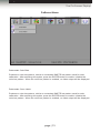
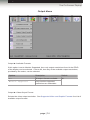


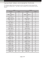


![XLite ToolSet Software [v05]](http://vs1.manualzilla.com/store/data/006304861_1-6990b54c95ba147b0c6f68f733c5e98d-150x150.png)
