1
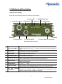
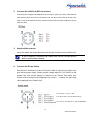
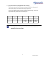
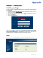
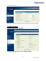
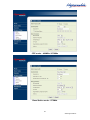
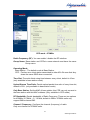
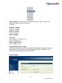
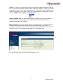
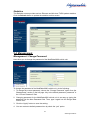
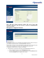
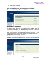
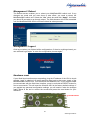
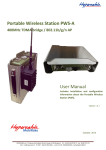
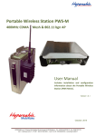
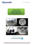
MobiRake20 Mobile Solution OFDM-TDMA Vehicle Unit UHF Band – 400MHz / 500 MHz / 873MHz / 918MHz User Manual Includes install, configuration and trouble shooting information for the broadband wireless access outdoor radio. Version 1.0.4 1 www.hypercable.fr Copyright Copyright © 2012 all rights reserved. No part of this publication may be reproduced, adapted, stored in a retrieval system, translated into any language, or transmitted in any form or by any means without the written permission of the supplier. About This Manual This manual includes install, configuration and trouble shooting for the 400MHz / 873MHz Licensed band Vehicle Unit. It can help you in avoiding the unforeseen problems and use the wireless VSU correctly. Technical Support If you have difficulty resolving the problem while installing or using the wireless VSU, Please contact the supplier for support. 2 www.hypercable.fr Table of Contents CONVENTIONS ..................................................................................................................................................................... 4 CHAPTER 1 INTRODUCTION ....................................................................................................................................... 5 1-1 FEATURES AND BENEFITS ............................................................................................................... 5 CHAPTER 2 HARDWARE INSTALLATION................................................................................................................. 7 2-1 PRODUCT KIT ................................................................................................................................. 8 2-2 SYSTEM REQUIREMENTS ................................................................................................................ 8 2-3 MECHANICAL DESCRIPTION ........................................................................................................... 9 INSTALL THE VEHICLE SUSCRIBER UNIT ........................................................................................ 10 CHAPTER 3 CONFIGURATION .................................................................................................................................. 13 3-1 START-UP AND LOG IN .................................................................................................................. 13 3-2 WIRELESS SETUP .......................................................................................................................... 15 3-4 MANAGEMENT ............................................................................................................................. 21 CHAPTER 4 VOLTAGE – POWER & CABLE NEEDS ................................................................................................. 26 4-1 MOBIRAKE SPECIFICATIONS ......................................................................................................... 26 4-2 FODU & INDOOR SPECIFICATIONS ............................................................................................... 26 3 www.hypercable.fr Conventions This publication uses the following conventions to convey instructions and information: This symbol means reader take note. Notes contain helpful suggestions or references to materials not contained in this manual. This symbol means reader be careful. In this situation, you might do something that could result in equipment damage or loss of data. This warning symbol means danger. You are in a situation that could cause bodily injury. Before you work on any equipment, be aware of the hazards involved with electrical circuitry and be familiar with standard practices for preventing accidents. 4 www.hypercable.fr Chapter 1 Introduction MobiRake Mobile Data Solution - 400MHz / 873MHz Licensed band Vehicle Unit is a cost-effective point-to-point / point-to-multipoint solution for Licensed band wireless mobile data transmission deployment and could be equipped with Ethernet interface. This Licensed band VSU provides customers with the greatest flexibility to deploy applications due to customers’ need and would be easily upgraded or switched to another interface with the lowest cost. This licensed band Vehicle Unit is incorporated with Time Division Duplex technology that they could be operated on a single channel. With highly-powered OFDM-TDMA technology, this radio is a long distance high capacity vehicle unit for 400MHz / 873MHz licensed UHF band. 1-1 Features and Benefits Effective spectrum utility / variable capacities 400MHz radio has 2 channel bandwidths (5/10MHz) for optional, which is adjustable via software. This function provides flexibilities of channel plan and variable capacities for different applications. FLEXIBILITY Detachable antennas allow operators to select the optimum antenna for specific environments. MANAGEABILITY Through the Web-based utility, the Wireless VSU is fully manageable locally and remotely. In addition, built-in SNMP support lets the operator, whether ISP or enterprise, expand the network infrastructure with ease. FETURES Provides the easy installation and high performance outdoor PTP / PTMP wireless mobile network up to 20 KM. Technique operating in the 400MHz / 873MHz. 5 www.hypercable.fr Transmit Power Control : Supports settable transmit power levels to adjust coverage cell size, ranging f from full, half(50%), quarter(25%) eighth(12.5%) and min Provides WEP-128 bits AES-256 bits as well as MAC access control to increase security. Provides Web-based configuration utility, user friendly interface. Support SNMP (Simple Network Management Protocol) for management. IP-68 rated weather-proof housing 6 www.hypercable.fr Chapter 2 Hardware Installation This chapter describes initial setup of the MobiRake20 vehicle unit. Warnings In order to comply with international radio frequency (RF) exposure limits, dish antennas should be laced at a minimum of 8.7 inches (22 cm) from the bodies of all persons. Other antennas should be laced a minimum of 7.9 inches (20 cm) from the bodies of all persons. Do not work on the system or connect or disconnect cables during periods of lightning activity. This equipment must be grounded. Never defeat the ground conductor or operate the equipment in the absence of a suitably installed ground conductor. Contact the appropriate electrical inspection authority or an electrician if you are uncertain that suitable grounding is available. Ultimate disposal of this product should be handled according to all national laws and regulations. Do not locate the antenna near overhead power lines or other electric light or power circuits, or where it can come into contact with such circuits. When installing the antenna, take extreme care not to come into contact with such circuits, as they may cause serious injury or death. For proper installation and grounding of the antenna, please refer to national and local codes. Only trained and qualified personnel should be allowed to install, replace, or service this equipment. To meet regulatory restrictions, the radio and the external antenna must be professionally installed. The network administrator or other IT professional responsible for installing and configuring the unit is a suitable professional installer. Following installation, access to the unit should be password protected by the network administrator to maintain regulatory compliance. The 400MHz / 873MHz licensed band radio and POE injector can be damaged by incorrect power application. Read and carefully follow the installation instructions before connecing the system to its power source. Follow the guidelines in this chapter to ensure correct operation and safe use of the licensed band radio. 7 www.hypercable.fr 2-1 Product Kit Before installation, make sure that you the following items: 400MHz / 873MHz Licensed band VSU………….....……....…………..x 1 Terminal Block………………..………………….………………………...x 1 Product CD………………………………………………………..……..….x 1 Quick Installation Guide……………………………….……………..…..x 1 NOTE: If any of the above items are missing or damaged, please contact your local dealer for support. System Requirements 2-2 System Requirements Before installing the 400MHz / 873MHz Licensed band VSU, please make sure that these requirements have been met: A 10/100 Mbps Local Area Network device such as a hub or switch. (optional) Category 5 SSTP or SFTP networking cable. (From the VSU to PC) A Web browser for configuration: Microsoft IE 5.0 or later, or Netscape Navigator 5.0 or later version. Installing TCP/IP protocol to the computer. 8 www.hypercable.fr 2-3 Mechanical Description Vehicle Unit (VSU) Please refer to the following table for the meaning of each feature. 3. Power LED 1. Power Input (M12) 4. LAN Active 2. LED Switch 7. Power Switch 5. RSSI LED indicator 8. LAN Port (M12) 6. Reset button 9. N- Jack Antenna Connector Vehicle Subscriber Uuit Figure Feed 10~30VDC power to the Vehicle Unit via this power Jack, please follow the pin assignment for correct + / - polarity, mix that might cause the damage of radio. Switch up: Turn on the LED indicators Switch down: Turn off the LED indicators 1 Power Input (M12) 2 LED Switch 3 Power LED Indicate status of power on or off. 4 LAN Active LED Indicate status of LAN active 5 RSSI LED indicator This function only works at CPE mode to indicate the RSSI from Basestation, 5 LEDs (levels) totally, more LEDs means stronger signal level. 6 Reset button press it and hold the reset button for 5~10 seconds, the Vehicle Unit will back to factory default settings. 7 Power Switch ○: OFF 8 LAN Port (M12) 9 N- Jack Antenna Connector / —: ON Use the SFTP cat.5 cable with M12 connector to connect to the Vehicle Unit, and the other end to other Ethernet device such as PC or switch / router. Here you can attach the proper antenna with the Vehicle unit to wirelessly connect to the networks. In order to improve the RF signal radiation of your antenna, proper antenna installation is necessary. 9 www.hypercable.fr INSTALL the Vehicle Suscriber Unit This section show you how to mount the Vehicle unit, please read it carefully before you start to install the hardware. Be safe and step by step to finish the hardware installation. Discone Antenna To Antenna 10~30VDC 10/100 BaseT Ethernet Device Hardware Installation Figure This vehicle unit can be damaged by incorrect power application. Read and follow the installation instructions carefully before connecting the system to its power source. 1. Mounting the vehicle unit in the car Only trained and qualified personnel should be allowed to install, replace, or service this equipment. 10 www.hypercable.fr 2. Connect the LAN Port (M12 connector) This Vehicle Unit support 10/100M Ethernet connection. Attach your SFTP cat.5 Ethernet cable with the M12 connector on the Vehicle Unit, and then connect the other end of the cable to the other Ethernet devices. Please follow the below pinouts assignment for the Ethernet cable. 3. Attached the antenna Users can attach the proper antenna to the N-type connector on the Vehicle Unit. To meet regulatory restrictions, the Vehicle Unit and the external antenna must be professionally installed. 4. Connect the Power Cable Use the M12 connector to make a DC power cable to connect the Vehicle Unit and Vehicle power supply. Feed in proper voltage range DC (10~30VDC) to the Vehicle Unit with correct polarity to make sure the Vehicle Unit works well. Please refer to below pinouts assignment for correct + / - polarity, mix that might cause damage to the Vehicle Unit. Pin 1: Brown – marron + VDC Pin3: Blue –Bleu –VDC (for Moxa switch) Pin 5: Green –Vert Masse et – VDC for MobiRake 11 www.hypercable.fr 5. Align the antenna by the RSSI Bar Led or beeper This function only works at CPE mode to indicate the RSSI from Basestation, 5 LEDs (levels) totally, more LEDs means stronger signal level. You can hear different tempo of beeper in different signal strength,there are 5 signal levels totally, please refer to the following list. Signal level 1(Min) 2 3 4 5(Max) RSSI -92~-88dBm -87~-78dBm -77~-63dBm -62~-43dBm -42~+10dBm LED Status 1* Yellow 2 * Yellow 2 * Yellow + 1 * green 2 * Yellow + 2 * green 2 * Yellow + 3 *green You should read and follow the installation instructions carefully before connecting the system to its power source. This wireless Vehicle Unit can be damaged by incorrect power supply. 12 www.hypercable.fr Chapter 3 Configuration 3-1 Start-up and Log in In order to configure the OFDM-TDMA Vehicle Unit, use the web browser and please do the following: 1. Type the IP address http://192.168.1.1 of this radio in the Location (for IE) or Address field and press Enter. 2. Enter the system name (the default setting is “admin”) and password (the default setting is “password”). 3. Click on the “Login” button. After you have logged-in the main page, the About, Basic Setup, Wireless Setup, Status, Statistics, Management and Logout buttons will be shown. The main menu provides links to the whole sections of the web configuration interface. About The About screen describes the product information briefly. Information of the radio includes Device Name, MAC Address, and Firmware Version information. 13 www.hypercable.fr Basic Setup / IP Setup The Device Name is used to give a name to your MobiRake2000 vehicle unit. This will enable you to manage it more easily if you have multiple radios on your network. Ethernet Data Rate: you can choose the Ethernet data rate you need VLAN (802.1Q): enable this feature and assign a management Vlan ID to the radio. Those PC without same Vlan ID will not be allowed to connect this radio and configure it. IP Address: Type the IP address you want to set to your MobiRake2000 vehicle unit. (Default: 192.168.1.1). IP Subnet Mask: The MobiRake2000 vehicle unit’s Subnet Mask must be the same as your Ethernet network. We recommended that you do NOT change the value. (Default: 255.255.255.0). Default Gateway: The MobiRake2000 vehicle unit will use this value for default Gateway. Primary DNS Server: The MobiRake2000 vehicle unit will use this value for primary Domain Name Server. Secondary DNS Server: The MobiRake2000 vehicle unit will use this value for secondary Domain Name Server. Basic Setup / STP Setup Spanning tree protocol (STP): You may Enable or Disable the Spanning Tree 14 www.hypercable.fr Protocol used in this radio. Note: If you complete the settings, please click on “Apply” for changes to take effect. 3-2 Wireless Setup Wireless Setup / Radio Settings Base Station mode - 400MHz / 873MHz 15 www.hypercable.fr CPE mode – 400MHz / 873MHz Base Station mode - 873MHz 16 www.hypercable.fr CPE mode - 873MHz Radio Frequency (RF): You can enable / disable the RF interface. Group Name: Base station and CPEs in same network must have the same Group name. Operating Mode: Base Station:The default mode is Base Station. CPE:Perform as a client station associated to other APs. Be sure that they share the same SSID when connected. Time Slot: Time slot divide using time between every client, default is 10ms. (only available in base station mode) Upload Stream Time Ratio: Decide upload packet time ratio of every time slot, default is 50%. (only available in base station mode) Only Base Station: Set the MAC of base station, this CPE can only connect to the base station with this MAC address. (Only available in CPE mode) RF Bandwidth: Decide bandwidth of Radio Frequency. There are two options for 400MHz / 873MHz -- 5 / 10 MHz, default is 5MHz. 873MHz radio only support 5MHz channel BW. Channel / Frequency: Configure the channel (frequency) of radio. Only one channel for 873MHz radio. 17 www.hypercable.fr TX Rate Range: Normally choice transmission rate as “Best”, system will adapt best rate for real environment. Including: 64QAM 3/4, (54Mbps) 64QAM 2/3, (48Mbps) 16QAM 3/4, (36Mbps) 16QAM 1/2, (24Mbps) QPSK 3/4, (18Mbps) QPSK 1/2, (12Mbps) BPSK 3/4, (9Mbps) BPSK 1/2, (6Mbps) TX Power : Setting power of TX, default is Full Half: -3 dBm from full Quarter: -6 dBm from full Eighth: -9 dBm from full Min: -12 dBm from full Fragmentation packet length: Decide the length of the maximum fragmentation packet. When packet is large than setting, it would divide to smaller segment package. By default, it will divide the length of segment packet automatic Security/Cipher 18 www.hypercable.fr Cipher :To prevent unauthorized radios from accessing data transmitted over the link, the Encryption Settings window offers WEP/AES features, making your data transmission over air more secure and allows you to specify Encryption Key(s) if you enable encryption for the radio. There are three degrees of encryption could be selected: NONE, 128 bits WEP and 256 bits AES. Cipher Phrase: After you select the encryption, please key-in the same phrase in this field of the both radios (local and remote) and then press apply, radio will generate a password automatically. Flow control Flow control is the process of managing the rate of data transmission between two nodes to prevent a fast sender from outrunning a slow receiver. It provides a mechanism for the receiver to control the transmission speed, so that the receiving node is not overwhelmed with data from transmitting node. PS. this function only available in Base Station mode 19 www.hypercable.fr Status The status page of Base station mode provides below information from remote CPEs: MAC Address, IP Address, RSSI, Rx rate, remote RSSI(RSSI value of remote CPEs – for easier antenna alignment in the field), Tx rate. Base Station Mode The status page of CPE mode provides below information from remote Base station: Group Name, MAC Address, Channel, Encryption, RSSI, IP Address, Rx rate, remote RSSI (RSSI value of BS – for easier antenna alignment in the field), Tx rate. CPE Mode – 400MHz / 873MHz CPE Mode – 873MHz 20 www.hypercable.fr Statistics The Statistics screen provides various Ethernet and Wireless TX/RX packet statistics. Click the Refresh button to update the statistics on this screen. 3-4 Management Management / Change Password Here allow you to change the password of the MobiRake2000 vehicle unit. To change the password of the MobiRake2000 vehicle unit, do the following: 1. To change the current password, choose the “Change Password” option from the “Management” section in the left page. Key-in the default password “password” in the “Current Password” filed. 2. Changing password for the MobiRake2000 vehicle unit is as easy as typing the password into the New Password field. Then, type it again into the Retype New Field to conf 3. Click the “Apply” button to save the setting. 4. You can restore to default password too by check the “yes” option. 21 www.hypercable.fr Note: After you change password, please take note of your new password. Otherwise, you will not able to access the MobiRake2000 vehicle unit setup. Management / Upgrade Firmware The Upgrade Firmware menu will display the Upgrade Firmware window so that you could update the latest firmware on the MobiRake2000 vehicle unit. Please make sure that you have downloaded the latest and correct firmware from the website before upgrading the firmware of the MobiRake2000 vehicle unit. To upgrade the latest firmware, complete the following: Using browser to access the main page of the MobiRake2000 vehicle unit. 1. Select “Upgrade Firmware” from the Management section. 2. Input the exact file path and name or select the file by clicking Browse button, then press Upload button to upgrade the firmware. 22 www.hypercable.fr 3. Please wait for few seconds. If download fail, please repeat the step 1~3 to download again. Note! Do not power off the unit when it is being upgraded. Management / Backup / Restore Settings Management / Time Setting The current system settings can be saved into a file as a backup by clicking “Backup”. The saved file can be loaded back on the radio by clicking “Browse”. When you have selected the settings file, click “Retrieve” to begin the process. Furthermore, you may click “Restore” to factory default settings. Time: While you connect this MobiRake2000 vehicle unit to Internet, it could automatically synchronize the current time with the Time Server that you have set. Time Server: the central time of the Time Server. Time Server Port: the port of the Time Server. Time Zone: You may select the appropriate local time zone for your radio from a list of all available time zones. Default: GMT. 23 www.hypercable.fr Management / Event Log Enable SysLog if you have a Syslog Server on your network environment. If enable, you need to input the Syslog Server IP Address (default is 0.0.0.0) and the port number your Syslog Server is configured to use. The default port number is 514. The Event Log Window lists MobiRake2000 vehicle unit events. Click on “Refresh” to update the network events or “Save As…” to save the event into a file on your computer. Click “Apply” if you made any changes. 24 www.hypercable.fr Management / Reboot The Reboot screen enables you to reboot your MobiRake2000 vehicle unit. If any changes are made and you want them to take effect, you need to reboot the MobiRake2000 vehicle unit. Select the “Yes” check box and click “Apply”. It will take you about 50 seconds to go through reboot. The Web-browser will not be accessible until the MobiRake2000 vehicle unit has finished its reboot process. Management / Logout Click log out when you finished all the configurations, if there is anything missed, you can selected “login again” to enter the configuration process again. Hardware reset If your Web User Interface stops responding, ping the IP address of the VSU to check whether “reply” is obtained, or unplug and then plug back in the power supply of the MobiRake2000 Vehicle unit. This will reboot the Wireless VSU. If you are still unable to communicate with the Web User Interface, press in and hold the RESET button for five to ten seconds. This will reset the Wireless VSU to the factory default settings. If you applied any personal configuration settings, you will need to make the changes again. Below is the tool to revolve the screws and press the reset button for your reference: Reset button 25 www.hypercable.fr Chapter 4 Voltage – power & cable needs 4-1 MobiRake specifications Model (Indoor / Vehicle) 873 MHz 5W DC input range 10~30V DC MobiRake Vehicle Unit Pure Tx mode Pure Rx mode Power consumption Main board + RF module (Max. 16.8W) 12VDC 1.4A 1.2A Power cable 24VDC 0.75A 0.6A MOXA AWG Number 21 AWG (0.723mm) MAX current * 1.2~1.6A Hypercable 20 AWG (0.812mm) 1.5~2A 4-2 FODU & Indoor specifications Modèle (Extérieur POE) 800MHz 5W Tension d’alimentation 15~35V DC 400MHz 5W 15~35V DC 2.4GHz / 5GHz 0.2W 15~35V DC Modèle (intérieur et véhicule) 800MHz 5W Tension d’alimentation 10~30V DC 400MHz 5W 10~30V DC 2.4GHz / 5GHz 0.2W 10~30V DC Puissance consommée Carte mère et module radio (Max. 16.8W) + chauffage (12W) Carte mère et module radio (Max. 13.8W) + chauffage(12W) Carte mère et module radio (Max. 8W) + chauffage (12W) Puissance consommée Carte mère et module radio 16.8W) Carte mère et module radio 13.8W) Carte mère et module radio (Max. (Max. (Max. 8W) 26 www.hypercable.fr 27 www.hypercable.fr