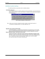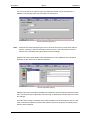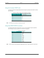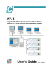
1
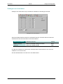
WA-32 Enhancement Software For AM-32/AM-32VGA In-Picture Audio Meter/Alarm Systems User’s Guide Version 2.4 12/08/05 Chromatec WA-32 Michael Stevens & Partners Ltd. has made every effort to ensure the accuracy of information contained within this document which is nevertheless supplied for information purposes only and does not constitute any form of warranty or guarantee. All trademarks acknowledged. The information in this document is subject to change without notice. Michael Stevens & Partners Ltd Invicta Works Elliott Road Bromley Kent BR2 9NT UK Tel: +44 (0)20 8460 7299 Fax: +44 (0)20 8460 0499 Email: [email protected] web site: www.michael-stevens.com www.chromatec.com 2009 Michael Stevens & Partners Ltd Chromatec WA-32 Contents INTRODUCTION Main Features USING THE CONTROLLER Running the Controller for the first time Logging in Selecting a frame Controlling bar graphs Test signals Assignments Main cursor Alarm status Muting alarms Uploading presets AES/EBU receiver status Timecode display USING THE CONFIGURATOR Running the Configurator for the first time The Configurator tool bar Logging in Applying changes Saving and loading configuration files. Hardware options and assignments status GENERAL ATTRIBUTES Video attributes Audio Monitor Peak hold Timecode attributes 1 1 2 2 2 2 3 3 3 3 3 4 4 4 5 6 6 6 7 7 7 7 8 8 8 9 9 SCALE ATTRIBUTES BAR ATTRIBUTES LEVEL BAR ATTRIBUTES PHASE BAR ATTRIBUTES USING LABELS USING GROUPS SETTING ALARMS 10 11 11 13 14 15 16 Showing alarms Alarms auto reset 16 16 2009 Michael Stevens & Partners Ltd Chromatec WA-32 Defaults Video loss alarm Audio loss alarm Carrier loss alarm Anti-phase alarm Analogue over level alarm Digital over level alarm USING THE UPLOADER Logging in THE EVENT LOG DATABASE USING THE REPORT VIEWER The Report Viewer tool bar Using grid view Using record view Running reports DATABASE MAINTENANCE Logging in 16 17 18 19 20 21 22 23 23 24 24 24 25 25 26 28 28 SCHEDULING EVENTS 29 The Scheduler tool bar Logging in Adding a new task Scheduling events 29 29 30 31 SOLVING OPERATIONAL PROBLEMS Sample operational problems and their solutions INSTALLATION Minimum pre-requisites: Using PC ports INSTALLING THE WA-32 SOFTWARE Installation trouble shooting SETTING UP THE SERVER Editing Server properties APPENDIX A Using the command line APPENDIX B Using the RS Components converter Using the Acceleport RS422 card Using other RS422-RS232 converters 2009 Michael Stevens & Partners Ltd 32 32 33 33 33 34 35 36 37 40 40 42 42 43 43 Chromatec WA-32 Introduction Introduction The Chromatec WA-32 software suite is designed to control up to four AM-32 or AM-32VGA In-picture Audio Meter and Alarm Systems. It integrates remote control and remote configuration and considerably enhances usability and flexibility. Additionally, alarm and status information may be accessed via a network. The WA-32 Enhancement Software package operates within the familiar Windows® environment. Main Features • Client server architecture allows control and configuration on a single PC or over a network • Full remote control and configuration for up to four AM-32 or AM-32VGA units • Access alarm and status information over a network • Full logging of alarm events to disk for up to 32 audio channels • System event logging and reports • Serial control of optional external input video switcher (AM-32 only) so that background video can be made to follow monitored audio The WA-32 software will run on Windows 98 Second Edition, Windows NT4 and Windows 2000. It will not run on Windows 95 or Windows 98 First Edition. Note: This manual should be read in conjunction with the Chromatec AM-32 user manual. 2009 Michael Stevens & Partners Ltd 1 Version 2.4 Chromatec WA-32 Using the Controller Using the Controller The Controller application provides remote monitoring of video and audio alarm status for selected AM-32 frames. In addition bar graphs/test signals can be inserted and preset configuration files can be uploaded. Configurator files or Presets are created using the Configurator. The main Controller form Running the Controller for the first time The Server must be running before the Controller is run. When run for the first time, the Controller will request the TCP/IP address of the PC on which the Server is running. In addition it will ask if alarm logging is required from this copy of the Controller. Only reply NO to logging if there is, or is likely to be, another Controller logging alarms for the same frame. This is to prevent duplicate alarms for the same unit in a distributed system with multiple Controllers and frames. Please refer to the Solving operational problems chapter if this causes problems. If all programs are run on the same PC, then ‘localhost’ may be entered as the TCP/IP address. If the Server is run on a different PC then enter the Server’s TCP/IP address or name. The Server is discussed in the Installation chapter. The Controller can be run from the Chromatec program group via the start menu or from the Launch Pad as described in the Installation chapter. Logging in Click on ‘Login’ in the tool bar and Log in to the application by entering the appropriate user name and password. This will provide access to the Controller. Selecting a frame Use the Control drop down list to select an AM-32 frame to control. If necessary click on the padlock symbol to lock the selected frame’s local controls. 2009 Michael Stevens & Partners Ltd 2 Version 2.4 Chromatec WA-32 Using the Controller Controlling bar graphs Bar graphs may be inserted into the video channel of the AM-32 by clicking on the ‘picture’ icon next to the ‘padlock’ icon. Click the video icon again to turn inserted bars off. The slider below the padlock and video icons controls the fade level of the inserted bars. Test signals The ‘picture’ icon to the immediate left of the ‘padlock’ icon also controls the insertion or removal of test signals. With Insert On showing in the lower status bar, right click the ‘picture’ icon until Test Pattern OFF appears in the lower status bar. Continue to right click to cycle through the available test signals. Left click the ‘picture’ icon to return to Insert On/Off. Assignments The Assignments status should show the current assignments of the frame Audio Monitor output, the Phase Bar at the top of the AM-32 in-vision display and the optional video select source. Please refer to the Using the Configurator chapter for details of assignment changes. Main cursor The main cursor allows the audio monitored to be moved to a particular channel pair by clicking that pair’s alarm window or by clicking on the left and right Main cursor arrows. Alarm status The alarm status of the selected video source for video loss and up to 16 audio pairs is shown in the Monitoring and Alarm Status boxes. If a monitored event has occurred the alarm box will flash red. Double click on the flashing box to reveal the Alarm Status display. The Controller Alarm Status for channels 19 and 20 In this case channel 20 has experienced audio loss. Click Reset to reset the alarm, otherwise click OK to dismiss the Status Alarm display. Note: A reset alarm will return after the Set Time period for that alarm if the triggering event has not been removed. In this case channel 20 restored to normal level. 2009 Michael Stevens & Partners Ltd 3 Version 2.4 Chromatec WA-32 Using the Controller The Alarms in System icon will also flash even if the event triggering that alarm is present on a frame not currently selected by the Controller for monitoring. Muting alarms An audio alert in the form of a .wav file can be sent to any sound card and connected speakers on the PC on which the Controller is running. This alarm can be muted by clicking on the Sound On icon, by using the Mute Alarm function in the Options menu or by clearing the fault that triggered the alarm(s). Uploading presets Configuration files or presets can be uploaded to the monitored AM-32 frame from the Upload command in the Preset menu. Please refer to the Using the Configurator chapter for details of creating configuration files. It is possible to schedule uploads of different configuration files using the Scheduler to alter the configuration of one or more AM-32 frames at set times. The Scheduler is discussed in the Scheduling events chapter. AES/EBU receiver status The receiver status of all digital channels can be viewed by enabling it in the View menu. The AES/EBU Receiver Status display 2009 Michael Stevens & Partners Ltd 4 Version 2.4 Chromatec WA-32 Using the Controller Timecode display If the timecode option is fitted, timecode can be viewed by enabling it in the View menu. The timecode display Note: The timecode display is for guidance only and cannot be guaranteed to be frame accurate as Windows only updates it at irregular intervals. 2009 Michael Stevens & Partners Ltd 5 Version 2.4 Chromatec WA-32 Using the Configurator Using the Configurator For new systems, or if Chromatec modules or frames have been added or removed, the Configurator should be used to assign required alarms and select audio and video monitoring options. Running the Configurator for the first time The Server must be running before the Controller or Configurator is run. When run for the first time, the Configurator will request the TCP/IP address of the PC on which the Server is running. If all programs are running on the same PC, then ‘localhost’ can be entered as the TCP/IP address. If the Server is run on a different PC then enter the Server’s TCP/IP address or name. The Server is discussed in the Installation chapter. The Configurator can be run from the Chromatec program group via the start menu or from the Launch Pad as described in the Installation chapter. However, in systems with multiple AM-32 frames it is recommended to launch the Configurator from the Controller Edit menu. In this way, the Configurator will always access the AM-32 frame selected in the Controller frame control spin box. The Configurator tool bar Load and Save Configuration commands can be accessed from the File menu or the Tool Bar. However, only the Tool Bar provides access to the Undo, Apply global defaults, and the Upload/Download configuration commands. The Configurator may be exited via the File menu, clicking on the Exit Configurator icon or be clicking on the cross at the right of the Configurator window in the normal way. Save Download Apply current AM-32 current configuration defaults configuration to PC Load Undo new configuration Upload new configuration to AM-32 Exit configurator The Configurator Tool Bar 2009 Michael Stevens & Partners Ltd 6 Version 2.4 Chromatec WA-32 Using the Configurator Logging in Click on ‘Login’ in the tool bar and Log in to the application by entering the appropriate user name and password. This will provide access to the configuration menus. Applying changes Configuration changes have no effect on the AM-32 or AM-32VGA until the the changes have been uploaded using the Upload new configuration tool (upward arrow in tool bar). Saving and loading configuration files. Changes may be saved to and loaded from a file. These configuration files can then be used as presets to configure one or more AM-32 frames using the Uploader or more conveniently from the Scheduler. The Scheduler is discussed in the chapter ‘Using the Scheduler’. Hardware options and assignments status If necessary use the ‘download current configuration’ tool (downward arrow in tool bar) to refresh the status and configuration screens. The Hardware Options section of the Information form should now show which cards or options are fitted in the current frame. Assignments and hardware The Assignments status section should show the current assignments of the frame Audio Monitor output, the Phase Bar at the top of the AM-32 in-vision display and the Video Select source (AM-32 with external switcher only). 2009 Michael Stevens & Partners Ltd 7 Version 2.4 Chromatec WA-32 Using the Configurator General attributes Use this form to configure Video, Audio Monitor, Peak Hold and Timecode attributes. Video attributes Configure video attributes or select defaults. Video attributes Video attributes Parameter selection Operating mode Composite, YUV, RGB Display Internal, External or Auto Internal Standard PAL or NTSC NTSC Pedestal Check this box to apply NTSC pedestal Defaults Click here to reset Video attributes to their default values (Composite, Auto, PAL) Audio Monitor Configure audio monitor output or select defaults. Audio monitor 2009 Michael Stevens & Partners Ltd 8 Version 2.4 Chromatec WA-32 Using the Configurator Audio attributes Parameter selection Mode Stereo, Sum, Left on both, Right on both Assign Channels 1&2 to 21&32 or Main cursor Defaults Click here to reset Audio attributes to their default values (Stereo, Main cursor) Peak hold Configure Peak hold attributes or select defaults. Peak hold attributes Peak hold attributes Parameter selection Enable Check this box to enable Peak hold Time Select 0.5, 1.0, 3.0, 10.0, 30.0 seconds or Infinite Indication colour Click this area to bring up 16 colour palette Defaults Click here to reset Peak hold attributes to their default values (Enabled, 3.0 secs, White) Timecode attributes Configure Timecode attributes or select defaults. Timecode attributes 2009 Michael Stevens & Partners Ltd 9 Version 2.4 Chromatec WA-32 Using the Configurator Timecode attributes Parameter selection Enable Check this box to enable timecode display Position Choose appropriate display position Format VITC or LTC Numbers colour Click here to select colour from palette Background colour Click here to select colour from palette Defaults Click here to reset Timecode attributes to their default values (Enabled - if option present, centre of screen, VITC, red numbers on black background) Scale attributes Configure Scale attributes or select defaults. Scale attributes Analogue scale attributes Parameter selection Type PPM (DIN, BBC, Nordic), VU, Extended VU Position Off, Both sides, Left side, Right side Analogue 0dB Ref 0 to +11dBu Digital scale attributes Parameter selection Type PPM (DIN, BBC, Nordic), VU, Extended VU, AES/EBU Position Off, Both sides, Left side, Right side Digital/Analogue Scale Ref 0 to –30dB Scale attributes Parameter selection Scale colour Click this area to bring up 16 colour palette Defaults Click here to reset Scale attributes to their default values (Analogue: DIN PPM Both sides, 0.0dBu Digital: AES/EBU, Both sides, -18dB) 2009 Michael Stevens & Partners Ltd 10 Version 2.4 Chromatec WA-32 Using the Configurator Bar attributes Configure Bar attributes or select defaults. Bar attributes Note: Show Analogue channel Parameter selection Off Check this box to disable analogue bars From/To Select the From/To range from the available channels Show Digital channel Parameter selection Off Check this box to disable digital bars From/To Select the From/To range from the available channels The available range is detected automatically from the AM-32 frame selected for control for both the digital and analogue channels Level Bar attributes The Level Bar attributes allows analogue or digital bars to be configured singly or in multiples using the Multi-Select facility. Use the Screen Label, Name/Description or Bar/Channel spin boxes to select a particular bar. The Name/Description spin box will be greyed out unless Keyboard label style has been selected. 2009 Michael Stevens & Partners Ltd 11 Version 2.4 Chromatec WA-32 Using the Configurator To select a range of bars before making changes use the Multi-Select tool. Multi-Select tool To select a series of multiple entries hold the Shift control down, whilst highlighting the desired channel range. To select discontinuous channels hold the Cntlr key down and highlight individual channels. The normal Windows selection techniques via the Shift and Ctrl keys are enhanced by the All, Invert and Alternate controls. 2009 Michael Stevens & Partners Ltd 12 Version 2.4 Chromatec WA-32 Using the Configurator The following parameters can be controlled: Level bar attributes Parameter selection Default Bar width 10 to 32 pixels 14 Next Bar Spacing 2 to 32 pixels 2 Over-range colour Select from 16 colour palette White Upper-range colour Select from 16 colour palette Yellow Lower-range colour Select from 16 colour palette Green Background colour Select from 16 colour palette Grey Analogue upper-range point -30dB to +12dB 0 Analogue lower-range point -30dB to +12dB -10 Digital upper-range point -30dB to +12dB -8 Digital lower-range point -30dB to +12dB -18 Phase Bar attributes The Phase Bar attributes allows the Phase Bar to be configured. Phase Bar attributes Parameter selection Default Enable Check this box to enable the Phase Bar Enabled Mode Choose Bar+Hold or Bar only Bar+Hold Assign Assign to main cursor or select a pair of channels Main cursor Multi-Indicators Choose between In+Out, Out only or OFF OFF Phase-In colour Click box to select from a palette of 16 colours Green Phase-Out colour Click box to select from a palette of 16 colours Purple Position Select Phase Bar vertical position Top Click the Defaults button to restore the Level Bars and Phase Bar to default settings. 2009 Michael Stevens & Partners Ltd 13 Version 2.4 Chromatec WA-32 Using the Configurator Using labels Numerical or five character alphanumeric labels may be applied to each Bar if required. Use the Labels form to create the labels. Assigning Labels in Keyboard style The displayed options depend on the style chosen. The Keyboard style (illustrated) provides a 5-character on-screen name field and a 40-character description field. The Numerical style applies numerical labelling and supports the 40-character description field. Selecting OFF in the style spin box turns of all labelling. Note: Label attributes Parameter selection Default Style Choose between OFF, Numerical and Keyboard Numerical Bar label colour Click box to select from a palette of 16 colours Yellow Screen name Enter five character name (Keyboard style only) 01 to 32 Description Channel01 to Channel32 (Keyboard or Numerical) Channel 01 to 32 Label form controls Parameter selection Screen name map Displays labels and provides direct entry Clear Clears all screen names and descriptions Defaults (next to clear button) Establishes labelling text/number defaults in ‘Default’ column, but not style or label colour The overall Defaults button at the bottom of the Label form recalls the Numerical style and establishes the default numerical bar labelling and colour. Any labels will be lost. Save the configuration (which will include any labels) before returning to Numerical style. 2009 Michael Stevens & Partners Ltd 14 Version 2.4 Chromatec WA-32 Using the Configurator Using groups Groups are automatically assigned to channels on the basis of the installed cards. Analogue cards will form one group and digital cards will form a second group. This form allows the meter operating mode, background colour, main cursor colour and overall vertical/ horizontal position to be chosen for ALL groups. The separation between groups may also be chosen. Groups attributes Note: The spacing control will be greyed out and disabled if only one group is present. (i.e. all analogue channels or all digital channels) The displayed options depend on the style chosen. The Keyboard style (illustrated) provides a 5-character on-screen name field and a 40-character description field. The Numerical style applies numerical labelling and supports the 40-character description field. Selecting OFF in the style spin box turns of all labelling. Note: Group attributes Parameter selection Default Meter Operating Mode Choose between Full, Half and Quarter Full Spacing Select spacing between groups in 32 increments Minimum Horizontal position Select overall horizontal position in 40 increments 5 increments Vertical position Select overall vertical position in 20 increments 5 increments Background colour Click box to select from a palette of 16 colours Black Main cursor colour Click box to select from a palette of 16 colours Cyan The Defaults button at the bottom of the Group form recalls the default values shown. 2009 Michael Stevens & Partners Ltd 15 Version 2.4 Chromatec WA-32 Using the Configurator Setting alarms The alarms attributes form provides access to the configuration of all AM-32 alarms. Alarm attributes Showing alarms The display of alarms with the level and phase bar graphs can be disabled without preventing the generation of external alarms. Check ‘Display Alarm Indicators’ to show alarms with the bar graphs. Alarms auto reset The time that an alarm remains asserted after a triggering event has occurred and has been cleared can be set with the Alarms Auto Reset spin box. Select between 0 seconds and 12 hours or OFF. Defaults Click Defaults to load ALL alarm defaults. 2009 Michael Stevens & Partners Ltd 16 Version 2.4 Chromatec WA-32 Using the Configurator Video loss alarm The video loss alarm is only activated when the video sync of the video input is absent for more than 300ms. Video Loss alarm Check the Enable Alarm box to show the video loss alarm. Note: The video loss alarm is NOT shown with the bar graphs display. It will be generated as an external alarm and appears on the WA-32 remote alarm monitor tool, the Chromatec Controller. 2009 Michael Stevens & Partners Ltd 17 Version 2.4 Chromatec WA-32 Using the Configurator Audio loss alarm Audio loss alarms may be enabled for individual or all channels. Audio Loss alarms Check the Enable Channels boxes for the desired channels. Check the All box to select all channels and click the Invert button to invert the selection. Audio loss variables Parameter selection Default Enable channels Select from 1 to 32 channels None Set time Select from 5 to 60 seconds 30 seconds Set threshold Select from –50 to 0 dB -30 dB The Set time variable is the duration that the audio level must lie below the Set threshold for audio loss to occur as an event. Use the defaults button to set this form to its default values. 2009 Michael Stevens & Partners Ltd 18 Version 2.4 Chromatec WA-32 Using the Configurator Carrier loss alarm Carrier loss alarms may be enabled for individual or all digital channels. Carrier Loss alarms Check the Enable Channels boxes for the desired channels. Check the All box to select all channels and click the Invert button to invert the selection. Audio loss variables Parameter selection Default Enable channels Select from 1 to 32 channels None Set time Select from 5 to 60 seconds 30 seconds The Set time variable is the duration that the audio level must lie below the digital carrier threshold for carrier loss to occur as an event. Use the defaults button to set this form to its default values. 2009 Michael Stevens & Partners Ltd 19 Version 2.4 Chromatec WA-32 Using the Configurator Anti-phase alarm Anti-phase alarms may be enabled for individual or all channels. Anti-phase alarms Check the Enable Channels boxes for the desired channels. Check the All box to select all channels and click the Invert button to invert the selection. Audio loss variables Parameter selection Default Enable channels Select from 1 to 32 channels None Set time Select from 0.25 to 10 seconds 1 second Set degrees Any negative (-ve) value, 45°+ and 90°+ 90°+ The Set time variable is the duration that the audio phase must lie outside the Set degrees threshold for a phase error to occur as an event. Use the defaults button to set this form to its default values. 2009 Michael Stevens & Partners Ltd 20 Version 2.4 Chromatec WA-32 Using the Configurator Analogue over level alarm Analogue over level alarms may be enabled for individual or all analogue channels. Analogue over level alarms Check the Enable Channels boxes for the desired channels. Check the All box to select all channels and click the Invert button to invert the selection. Audio loss variables Parameter selection Default Enable channels Select the available analogue channels None Set level Select from 0.0dB to 20 dB 8 dB The Set level variable is the level that the analogue audio must lie above for an over level condition to occur as an event. Use the defaults button to set this form to its default values. 2009 Michael Stevens & Partners Ltd 21 Version 2.4 Chromatec WA-32 Using the Configurator Digital over level alarm Digital over level alarms may be enabled for individual or all digital channels. Digital audio over level alarms Check the Enable Channels boxes for the desired channels. Check the All box to select all channels and click the Invert button to invert the selection. Audio loss variables Parameter selection Default Enable channels Select the available analogue channels None Set level/Samples Select from 0.0dB to -20 dB or 1 to 12 samples 0 dB The Set level/samples variable is the level or number of samples that the digital audio must lie above for an over level condition to occur as an event. Use the defaults button to set this form to its default values. 2009 Michael Stevens & Partners Ltd 22 Version 2.4 Chromatec WA-32 Using the Uploader Using the Uploader The Uploader is provided to upload configuration files to selected AM-32 frames. It may be run from the Chromatec program group, the Launch Pad or from within the Controller. Logging in Click on ‘Login’ in the tool bar and Log in to the application by entering the appropriate user name and password. This will provide access to the file and edit menus. The Uploader Uploading configuration files To upload a configuration file to a selected AM-32 frame proceed as follows: • Select the file by typing its full name and path or use browse • Select the frame to upload to • Click on Send The selected AM-32 will be configured with the selected preset. This operation may also be performed automatically at set times with chosen presets for specific frames by using the Chromatec Scheduler. 2009 Michael Stevens & Partners Ltd 23 Version 2.4 Chromatec WA-32 The event log database The event log database Event logs are created in a database format compatible with Crystal Reports. A Report Viewer is provided to read these logs and a Log Maintenance tool allows logs to be archived and compressed. These utilities may be run from the Chromatec program group or the Launch Pad. Using the report viewer The Report Viewer may be used to view all or selected events in browse or grid format. Standard or custom reports may be created, viewed and/or printed. Before the application loads, a choice of current or archived log will be presented. Log selection The choice made can be changed subsequently via the file menu. The Report Viewer The Report Viewer tool bar The Report Viewer tool bar provides easy access to the available commands. The Report Viewer may be exited via the File menu or by clicking on the cross at the right of the application window in the normal way. Exit Record view Grid view The Report Viewer tool bar 2009 Michael Stevens & Partners Ltd 24 Version 2.4 Chromatec WA-32 The event log database Using grid view The Report Viewer grid view may be useful in displaying the log contents in spread sheet format. The display may be sorted against each field, by clicking on the column header. Filters may also be applied. The Report Viewer grid format Using record view The Report Viewer record view allows log contents to be viewed item by item. Click on the arrow keys to navigate through the log. The Report Viewer record format 2009 Michael Stevens & Partners Ltd 25 Version 2.4 Chromatec WA-32 The event log database Running reports The main function of the report generator is to allow log contents to be printed. Select either ‘View ALL Events’ or ‘Create Custom Report’ then click on Run Report to display the log in a printable format. Creating simple custom reports The custom reports facility is a useful way of searching for specific data in the log. The search may be delimited by event date, User name, Application or event details. Creating simple custom reports To search for a specific event type, enable the Event field and enter the appropriate data. The Wilcard symbol ? can be used for a single character and the * symbol can be used for multiple characters. For example to search for instances where the Server has been started by a particular user, enable the User field and select a user, enable Applications and select Server and enable Event and type *Logged*. The report generated will only display events where the chosen user logged in to the Server. To search for alarms associated with a particular frame, type 2009 Michael Stevens & Partners Ltd 26 Version 2.4 Chromatec WA-32 The event log database the frame’s name in the Event field i.e *AM-32 1*. Use the name chosen when configuring Server properties. To search for the occurrence of specific alarms, use Expert mode. Creating custom reports in expert mode The expert custom reports facility is intended to be used by individuals familiar with Event Log database structure and Crystal Reports operations. Creating custom reports in expert mode Record selection formulae are used in almost exactly the same way they are used in Crystal Reports. There is one notable exception, string values must only be enclosed with single quotation marks. For further details of Crystal Reports operations, which are beyond the scope of this manual, please refer to the appropriate Crystal Reports documentation. 2009 Michael Stevens & Partners Ltd 27 Version 2.4 Chromatec WA-32 The event log database Database Maintenance The Database Maintenance utility is provided to allow logs to be periodically archived. Logging in Click on ‘Login’ in the tool bar and Log in to the application by entering the appropriate user name and password. This will provide access to the file and edit menus. Log maintenance The following parameters may be chosen when creating archives: • The data before which log records are archived – default ‘current date’ • The archive period – default 30 days • log compression – default compact The archive period may be changed through the Edit menu. Regular log archiving can be scheduled using the Chromatec Scheduler. 2009 Michael Stevens & Partners Ltd 28 Version 2.4 Chromatec WA-32 Scheduling events Scheduling events The Chromatec Task Scheduler provides a convenient tool to access Microsoft Scheduler with either general or Chromatec ‘robots’. At present the Chromatec robots supported are the Database Maintenance tool and the Preset Uploader. The Chromatec Task Scheduler The Scheduler tool bar The Scheduler tool bar provides easy access to the available commands. The Scheduler may be exited via the File menu or by clicking on the cross at the right of the Configurator window in the normal way. Delete task New task Refresh task list (F5) Edit task properties Run task The Scheduler Tool Bar Logging in Click on ‘Login’ in the tool bar and Log in to the application by entering the appropriate user name and password. This will provide access to the file and edit menus. 2009 Michael Stevens & Partners Ltd 29 Version 2.4 Chromatec WA-32 Scheduling events Adding a new task A new General or Robot task may be created by via the Edit menu or by highlighting any task in the task window and right clicking to reveal all the available commands. Clicking on New Robot Task will start the Robot Scheduling Wizard. Choose a suitable task name. Select the desired robot – in this case upload.exe in the Robots directory. Select the desired preset configuration from the Presets directory and select the frame to upload the configuration to. Click Finish to end the Wizard and launch Microsoft Scheduler to schedule the upload event. The Robot Wizard Note: A robot based on the Database Maintenance tool will use the Archive and Date settings already chosen – see the Database maintenance section of the Event log database chapter for more information. Clicking on New General Task will simply ask for a task name before running Microsoft Scheduler. 2009 Michael Stevens & Partners Ltd 30 Version 2.4 Chromatec WA-32 Scheduling events Scheduling events Microsoft Scheduler may be invoked by right clicking a task in the Chromatec Task Scheduler window and selecting Edit Task Properties, by highlighting a task and clicking the Edit Properties icon in the tool bar. Microsoft Scheduler Tasks can also be managed by using the Scheduled Tasks tool in the Accessories Program Group. However, the Microsoft tool will not automatically apply the correct command line options. Command line options are dealt with in Appendix A. Please refer to your operating system documentation or online help for assistance with using Microsoft Scheduler. 2009 Michael Stevens & Partners Ltd 31 Version 2.4 Chromatec WA-32 Solving operational problems Solving operational problems Installation or general inter-application communication problems are dealt with in the installation chapter. Sample operational problems and their solutions One or more bar graph attributes or alarm settings are completely misadjusted Use the global or individual Defaults controls to recall sensible values. Alternatively recall a recently saved stable configuration. The Phase display has been enabled but does not appear on stereo signals The Phase display only appears if stereo signals are out of phase by more than the threshold (default ± 90°) The Configurator information screen has no valid hardware options or assignments Check that the Server is running and connected to a populated AM-32 frame. If necessary use the Download Configuration tool to refresh the status and alarms data. Remember to save any wanted configuration data. A selected AM-32 frame configuration can be read, but not updated Check that the data port (port 1) of the frame is set to PC/AM32. If necessary, refer to the Installation chapter for help in trouble shooting Server port settings. The Video Select source cannot be changed from the Configurator Video Select can only be set from the local AM-32 controls. Set this to Main Cursor and use the cursor control in the Controller application to change the background video to match the audio monitor output when using an upstream video switcher. The Configurator needs to be changed to look at a different frame Remember to launch the Configurator from the Controller in a multiple frame system, having first selected the chosen frame. A Controller in a multiple frame system does not log alarms Please refer to Michael Stevens & Partners service department for further assistance. The Simple custom report cannot be made to search for specific alarms Use the Expert mode and create your own custom report to search in the Details field. 2009 Michael Stevens & Partners Ltd 32 Version 2.4 Chromatec WA-32 Installation Installation The Chromatec WA-32 Enhancement Software is designed for the AM-32 and AM-32VGA In-picture Audio Meter and Alarm Systems. The main application consists of a server application and two client applications, the Controller and the Configurator. The server MUST run on the same PC that the AM-32 unit(s) are physically connected to. The Controller, Configurator and utility applications may run either on the same PC as the server or on another PC that is on the same network as the server. Minimum pre-requisites: • A PC running Windows 98 Second Edition, NT4 with SP 5 or higher or Windows 2000 • A parallel or USB port dongle supplied with the WA-32 Enhancement Software package • An RS422 serial connection from the host PC to at least one AM-32 or AM-32VGA frame with at least one monitoring card • A serial port may also be required to control any upstream switcher option • Controlled AM-32 frames should have port 1 set to PC/AM32 • Ensure that the AM-32 has v2.3 firmware (or later) and the AM-32VGA has v1.5 firmware (or later) • A sound card and connected speakers to hear the audio alert .wav file Using PC ports No configuration is required of PC ports, but both a parallel or USB port for the software ‘dongle’ and at least one spare serial port must be available. The parallel ‘dongle’ has a through port to allow the onward connection of any device such as a printer. The AM-32 frame requires an RS422 connection to the PC. Unless the PC already has an RS422 port, an RS232 to RS422 converter for each PC serial port or an RS422 add-in card may be required. Notes: Chromatec recommends using the Chromatec model SDC-1 RS232 to RS422 converter which comes with specially wired cable. Other converters and their recommended cable requirements are shown in Appendix B. Additional serial ports (up to four in total) may be required on the host PC for additional AM-32 or AM-32VGA frames. 2009 Michael Stevens & Partners Ltd 33 Version 2.4 Chromatec WA-32 Installation Installing the WA-32 software Note: • To view all application windows, set graphics resolution to at least 1024 x 768 • Remove any previous version of the WA-32 software using the Add/Remove Programs application in the Windows Control Panel. Do not fit the DK2 dongle until WA-32 installation is complete. • Insert the WA-32 CD and the installation should start immediately – if it does not, run the setup.exe file on the CD • Obey any installation program prompts and restart the PC when prompted • If supplied with a parallel type DK2 dongle, ensure that this is fitted to athe parallel port of the host PC chosen to run the server before running the server programme. • If supplied with a USB type dongle, ensure that this is fitted to a free USB port of the host PC chosen to run the server. The PC will detect new hardware and begin searching for the appropriate driver. This is supplied as a separate file on the WA-32 CD-ROM. Follow the prompts to install the DK2 driver before running the WA-32 server programme. If upgrading from a version earlier than v2.0, backup custom files before erasing the existing Chromatec folder (usually C:\Chromatec). Then restore the custom files to the new Chromatec directory. If successful, the installation program will install a Chromatec program group and a task bar icon. Any of the installed programs may be run from the program group using Start>Programs>Chromatec or from the task bar icon. Please see the Operation chapter for an explanation of program features. 2009 Michael Stevens & Partners Ltd 34 Version 2.4 Chromatec WA-32 Installation Installation trouble shooting The following guide may help trouble shoot installation problems: Locked File Detected The installation program may need to update some files that Windows is using. These files can only be updated in a DOS session whilst Windows is rebooting. Select Reboot when prompted to update these files. Select reboot for Windows to update this file Tip: Make a note of the files changed during the installation and back them up prior to committing to the Reboot option in case other applications fail. Upgrade stops program initialisation If initialisation problems are experienced after performing an upgrade from a version earlier than v2.0, despite backing up and restoring custom files, the Windows Registry may need to be edited. Please contact Michael Stevens & Partners Technical Support for assistance. Server Window displays ‘Running in demo mode’ Check that the parallel or USB dongle has been correctly installed before running the server application. If necessary, repeat the installation of the DK2 driver from the supplied CD-ROM. This driver supports both the parallel and USB dongle types. The DK2 driver embedded in the WA-32 software only supports the parallel dongle. Suitable drivers are also available from: http://www.deskey.co.uk/deskey_downloads.php 2009 Michael Stevens & Partners Ltd 35 Version 2.4 Chromatec WA-32 Installation Setting up the Server Run the Server from the Chromatec program group or task bar launcher using the appropriate password. If this is the first time the Server has been run it must be configured to establish the following parameters: • A unique TCP/IP port number • Administrator and user names and passwords • Chromatec AM-32/AM-32VGA frame comm port assignment To enter the Server configuration for the first time use default password ‘ADMINISTRATOR’, remembering to change the administrator name and password afterwards and add any additional users. A TCP/IP port number will be requested. This number must be unique on your network (default 3128). See your network administrator to get an unused port number. st Server TCP/IP Settings – 1 time run Once this number has been confirmed click the OK button to continue. The Server Application will then minimise itself on the task bar. To continue setting up the Server double-click the Server Icon in the task bar, or right-click the Icon and choose Show Window. 2009 Michael Stevens & Partners Ltd 36 Version 2.4 Chromatec WA-32 Installation Editing Server properties To access Server properties select Properties from the Edit menu of the Server Window. The Server Window Note: Do not enter data into the Data In or Data Out windows or click on Send at this time. This facility is for software development purposes only. Server Properties (General) Use the Number of Devices spin box to select the number of devices the host PC can communicate with. Do not select more than are actually connected. Note: The Logging window in this form will also show the Chromatec packages installed on the PC. This information is also present in the splash graphic that may appear when the Server application loads (optional). 2009 Michael Stevens & Partners Ltd 37 Version 2.4 Chromatec WA-32 Installation For up to four devices, the Device Type and serial port (COM 1-8) can be selected. In addition a user-friendly name may be chosen for each device. Server Properties (Device 1) Note: If frames have been linked using the Link-In and Link-Out ports to create a 32-channel system, connect the host PC running the Server to Port 1 of the first frame. This port must be set to PC/AM32 using the frames local user settings. Password and user name details of the Administrator and any additional users should be entered from the Users form of Server Properties. Server Properties (Users) Password and user name MUST be different. Explanatory text may also be entered for each user. Use the plus sign to add users, the minus sign to delete them and the disk icon to save the changes. Once the Server setup is complete remove the properties form by clicking OK. Use the view menu of the Server Window to prevent the splash screen from showing if necessary and to hide the Server Window. 2009 Michael Stevens & Partners Ltd 38 Version 2.4 Chromatec WA-32 Installation The following applications are installed, by default, in the Chromatec program group when both the main WA-32 and Data Logging software is installed: • Chromatec Configurator – configures selected AM-32 frame • Chromatec Controller – controls display and monitors alarms for selected AM-32 frame • Chromatec Log Maintenance – compacts and archives log files • Chromatec Preset Uploader – uploads preset file to selected AM-32 frame • Chromatec Reporter – log viewer for all Chromatec events • Chromatec Scheduler – invokes and improves Microsoft Task Scheduler • Chromatec Server – communicates with AM-32 frames and Chromatec applications The installed applications can be run in a number of different ways: • From the Chromatec Program Group via the Start menu • From the Chromatec Launch Pad on the task bar • From other Chromatec applications • From the Scheduler • From the command line The Chromatec Launch Pad 2009 Michael Stevens & Partners Ltd The Chromatec Program Group 39 Version 2.4 Chromatec WA-32 Appendix A Appendix A Using the command line Many of the Chromatec WA-32 applications can be run from the command line with appropriate switches as shown in the following tables: Controller Command line switch Description -Ax Specifies which AM-32 frame is to be displayed Where x = number of AM-32 to be viewed (Valid Range 0-3) Example C:\Chromatec\AM32\Controller.exe -A2 Makes the Controller run and display the alarm status of AM-32 2 Configurator Command line switch Description -Ax Specifies the AM-32 for which the configuration is to be retrieved/edited Where x = number of AM-32 (Valid Range 0-3) -Nx Specifies Name of AM-32 Where x = name of AM-32 Example C:\Chromatec\AM32\Configurator.exe –A3 Makes the Configurator run and point to AM-32 3 2009 Michael Stevens & Partners Ltd 40 Version 2.4 Chromatec WA-32 Appendix A Uploader Command line switch Description -Rx This command line argument makes the Uploader run and send the specified AM-32 preset to the frame denoted by the Ax switch Where x = path of valid preset file -Ax Specifies which AM-32 to send the specified preset to. Where x = number of AM-32 (Valid Range 0-3) Example -Rc:\Chromatec\AM32\Presets\AllAlarmsOn.cfg -A0 Makes the uploader run as a hidden application and send AllAlarmsOn.cfg to AM-32 0 DB maintenance Command line switch Description -Px Specifies Server Task priority. Only valid for Windows NT and Windows 2000 machines Where x = S Standard task priority = H High task priorty Example C:\Chromatec\AM32\Robots\DBMaintenance.exe -PH Makes the DB Maintenance utility run at High task priority Note: In normal use the appropriate commands and switches are passed between applications automatically. The Chromatec Scheduler Wizard always applies the correct command line switches for the Uploader and DB Maintenance ‘robot’ utilities. 2009 Michael Stevens & Partners Ltd 41 Version 2.4 Chromatec WA-32 Appendix B Appendix B The SDC-1 Serial Data Converter is supplied with a 5 metre 3-pair RS422 cable wired for the AM-32. This cable has been wired to carry a +5V supply from port 1 of the AM-32 to the Chromatec SCD-1. No further adaptors are required to interface with 9 pin serial PC ports. 25 pin serial ports will require a standard 9 to 25 pin port adaptor. Cable requirements for other converters are discussed in this appendix. For further details please contact the appropriate supplier. Using the RS Components converter The RS Components RS422-RS232 converter part number 201-758 requires cable wired as shown: Cable from AM-32 RS422 port to RS422-232 converter AM-32 RS422 9 pin male ‘D’ connector Screw terminals on converter 2 4 3 5 7 3 8 6 Cable from RS422-232 converter to 9/25 pin PC serial port 25 pin male ‘D’ connector at converter 9 pin female ‘D’ connector for 9 pin PC serial port 25 pin female ‘D’ connector for 25 pin PC serial port 2 3 2 3 2 3 7 5 7 7 – 8 wired together 4 – 5 wired together Note: The switch on the RS converter should be set to the DCE position. The cable from the RS422-232 converter to the PC should not be longer than 3 metres. Pin numbers not shown do not need to be wired. 2009 Michael Stevens & Partners Ltd 42 Version 2.4 Chromatec WA-32 Appendix B Using the Acceleport RS422 card The Digi International Acceleport RS422 card will require a specially wired cable to interface with the AM-32. Cable from AM-32 RS422 port to Acceleport converter Note: Acceleport cable end 9 pin male ‘D’ connector AM-32 RS422 9 pin male ‘D’ connector Shell 5 6 8 7 3 8 7 9 2 Pin numbers not shown do not need to be wired. Using other RS422-RS232 converters The following table shows the AM-32 port 1 pin-out. This information may be required for those wishing to use port converters not covered in this appendix: AM-32 port 1 pin-out Note: Pin number Signal 1 +5V 2 Rx- 3 Tx- 4 GND 5 GND 6 +5V 7 Rx+ 8 Tx+ 9 GND Take care not to connect ground or signal wires to pin 1, which carries 5V for the SDC-1. 2009 Michael Stevens & Partners Ltd 43 Version 2.4