1
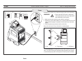
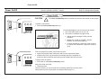
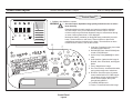
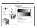
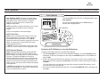
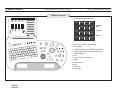
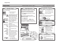
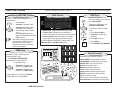
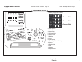
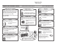
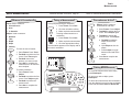
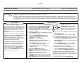
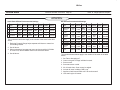
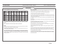
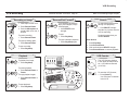
GE Medical Systems LOGIQ 700 Quick Start Guide Direction 2227865–100 Revision 0 E 1999 by General Electric Company Copyright User Documentation REVISION HISTORY REV DATE 0 DIRECTION 2227865–100 REASON FOR CHANGE May 21, 1999 6.5 and 8.0 Releases LIST OF EFFECTIVE PAGES PAGE NUMBER Title Revision History REVISION NUMBER 0 0 PAGE NUMBER 1–30 Back Page REVISION NUMBER PAGE NUMBER REVISION NUMBER 0 N/A Please verify that you are using the latest revision of this document. Information pertaining to this document is maintained on GPC (GE Medical Systems Global Product Configuration). If you need to know the latest revision, contact the GE Ultrasound Clinical Answer Center at 1–800–682–5327 or 414–524–5698, #1 for Applications; #5 for Ultrasound. GE Medical Systems GE Medical Systems: Telex: 3797371 P.O. Box 414, Milwaukee, Wisconsin 53201 U.S.A. (Asia, Pacific, Latin America, North America) GE Ultraschall: Deutschland GmbH & Co KG Beethovenstraße 239, Postfach 11 05 60, D–42665 Solingen GERMANY Tel: +49 (0) 212.28.08.208 Fax: +49 (0) 212.28.02.28 . USA Only CAUTION CAUTION: “United States law restricts this device to sale or use by or on the order of a physician” if sold in the United States. Read and understand the LOGIQ 700 Basic User Manual (2227866–100) and the Advanced Reference Manual (2227867–100) for operational details and safety concerns. LOGIQ 700 Illustration Direction 2227865–100 REV 0 Page 1 Refer To: Getting Started Chapter Front View 1. Peripherals. Peripherals are placed in front for Release 8.0 EXPERT and PRO Series or on top for Release 8.0 Update and 6.5. 2. Gel Holders. a. Top of Control Panel. Place the gel bottle here. b. Below Display Monitor. Warm and store the gel bottle here. 3. Speakers. Stereo speakers are provided for audio Doppler, VCR playback, and error notification. 4. Display Monitor. System imaging monitor. 5. Power Switch. On/Stand-by switch. 6. Probe Holders and Probes. All imaging probes can be plugged into any of the probe ports. Probes are automatically activated when the probe is lifted from its yoke (or manually via [Code S]), except for the 618e, 739 I/T. 7. Control Panel. All operator controls are located on the Control Panel. 8. Handles and Raise/Lower Button. Use the handles to move the system. Use the button to raise and lower the control panel. Push and hold the button while moving the control panel up/down. 9. Optical Disk. Optical disk and disk storage areas. 10.Brake and Footrest. The brake pedal and footrest (the footrest is not available on all systems). 11. Footswitch. Use the footswitch to freeze an image or to send an image to the designated hard copy device. ÏÏ ÏÏ ÏÏ ÏÏ LOGIQ 700 Illustration LOGIQ 700 Illustration LOGIQ 700 Illustration Direction 2227865–100 REV 0 Page 2 Refer To: Getting Started Chapter Back View 1. Storage Area. Use the storage area to store the Quick Start, VCR tapes, endocavitary probe, gel, sheaths, etc. 2. Peripherals. Peripheral shelf for Release 8.0 Update and 6.5. The printer sets across the peripheral shelf. The VCR can be set on top of the printer. If the VCR is the only peripheral, place it here. 3. Cord Wrap. Wrap the cord around the Power Cord Wrapping fixture provided in the back of the unit. 4. Footswitch Storage. Used to store the footswitch. 5. Connector Panel. Used to connect peripheral devices to the system. 6. Power Cord and Circuit Breaker. The Power Cord connects into the system here and the Circuit Breaker is located here. 7. Air Filter. The Air Filter is located in the back of the unit. Power Direction 2227865–100 REV 0 Page 3 Refer To: Getting Started Chapter Power 1. 2. To connect the system to the electrical supply (refer to the illustration), 4. OI WARNING 1. Ensure that the wall outlet is a dedicated 15/20 Amp branch circuit of the appropriate type, depending on the system. 2. Make sure that the system’s power switch is turned off. 3. Unwrap the power cable. Make sure you allow sufficient slack in the cable so that the plug is not pulled out of the wall if you move the system. 4. Push the power plug securely into the wall outlet. Keep unit one foot (30.5 cm) from wall or curtains/drapes. a b 3. c a. On b. Trip (Loose) c. Off (Reset) The Circuit Breaker is located at the back of the console, on the left side. It is used for turning off (disconnecting) all power to the system. It automatically trips power to the system in case of power overload. Power Power On/Off Power On/Off Direction 2227865–100 REV 0 Page 4 Refer To: Getting Started Chapter Power On/Off CAUTION I O The Power On/Stand-by switch is located on the front of the console on the left side. To power on the system, 1. Push the Power on/Stand-by switch up. LOGIQ 700 MR EXPERT Series The following happens over the next several minutes: 1. The control panel lights turn on, then off. 2. The system is initialized. During this time, S Start up status messages scroll across the SoftMenu. S Relays click on and the LOGIQt 700 MR, EXPERT, or PRO screen appears. S Controls available for a particular mode are dimly lit; controls not available for a particular mode are not lit. Prior to turning off the system, ensure that you have: S Made all necessary image, worksheet, and summary report hard copies. S Waited until archive copy and delete commands have been completed; all prints have been produced; and that all queued DICOM jobs have been sent. OI To power down the system, 1. Push down on the Power On/Stand-by switch. After power down each day: S Disinfect probes. Wait ten to fifteen (10–15) seconds before switching system back on after power down and do not turn off the system immediately after turning it on. Control Panel Layout Direction 2227865–100 REV 0 Page 5 Refer To: Getting Started Chapter Control Panel 1. SoftMenu plus SoftMenu controls. WARNING 2. Acoustic Output. Optimizes image quality and allows user to reduce beam intensity. 1 Read descriptions for each control you intend to use before adjusting Acoustic Output or any control that affects Acoustic Output. Use the minimum output to get the best diagnostic image or measurement during an exam. Values greater than 0.1 are displayed. Mechanical effects (cavitation) on biological tissue produced by acoustic beam. Thermal effects on soft tissue. Thermal effects on tissue with ossified bone near the focal point of the beam. Thermal effects on bone located near the surface, such as the cranium. 2 6 7 5 9 8 3 10 4 11 Control Panel Layout 3. Code Key. Pressing this key plus a letter activates system features. 4. DICOM End Exam. Sends DICOM jobs at end of DICOM exam. 5. Online Help. Press [Code H] for online help. 6. Auto Optimize. Optimizes the image in B Mode, Color Flow Mode, and Doppler Mode. 7. Zoom. Magnifies the image. 8. Set. Fixes cursors, accesses/exits tasks, and cycles through menu selections. 9. ROI Size. Sizes the region of interest, views recalled archive or CINE images one image at a time, pages through a series of menu pages, and cycles through body patterns. 10.Trackball. Multiple uses. 11. Freeze. Freezes/unfreezes the image. Monitor Adjustments Adjusting the Monitor Direction 2227865–100 REV 0 Page 6 Refer To: Getting Started Chapter Adjusting the Monitor Top View To adjust the Brightness, Press [Code K]. Click the VIDEO TEST PATTERN softkey. Images are recalled in a few moments. Press ROI Size until the following test pattern appears: 3 2 1. 2. 3. 4. 5. Brightness ALC On/Off Contrast Degaussing Control Ambient Light Control Sensor 1 5 Turn the brightness knob to the left or right until monitor’s background black matches the black in the upper, left-hand rectangle of the test pattern. This is probably not the detent position. To adjust the Contrast, S Turn the contrast knob to the left or right. S Increase the Contrast to display the complete or desired range of gray shades. Press Freeze to return to scanning. Do not change the controls once they have been set. Once set, the display then becomes the reference for the hard copy device(s). You can tilt the monitor up and down and pivot the monitor 85° to the left and right. Probes Direction 2227865–100 REV 0 Page 7 Connecting CAUTION 2. . Failure to lock the connector in place MAY CAUSE intermittent problems with probes already connected. Activating (Manual) Activating (Automatic) 1. Carefully remove probe from carrying case. DO NOT let probe head hang free. 2. Turn connector handle to horizontal position. 3. Place probe head 3. securely into probe connector yoke. 4. Align connector with probe port and carefully push into place. Lower the control panel to connect AMA probes to the third probe port 4. from the left. 5. Turn connector locking handle to the full vertical position. 5 Refer To: Getting Started and Probes Chapters 1. Carefully lift probe upward until probe is free of probe holder. 2. Carefully slide probe away from probe holder and around control panel. To manually activate a probe (618e, 739I/T), 1. Press [Code S]. 2. Click PROBE ID softkey corresponding to desired probe. To reset to automatic activation, 1. Press [Code S]. Click Previous/Next. 2. Click AUTO. Disconnecting 2. Deactivating . 1. Carefully slide probe around control panel toward its probe holder. 2. Match the colored ring on probe to colored ring on probe holder. 3. Place probe into its probe holder. DO NOT apply excess force to probe head or to probe holder. Follow recommended cleaning instructions after each use. Probes 1. Be sure that the probe head is clean before disconnecting the probe. 2. Place the probe in its corresponding probe holder. 3. Move the probe locking handle into the horizontal position. 4. Pull the probe and connector straight out of the probe port. 3. 5. Carefully slide the probe and connector away from the probe port and around the right side of the keyboard. 6. Ensure the cable is 4. free, then store the probe in its carrying case. Peripheral Setup Peripheral Setup Direction 2227865–100 REV 0 Page 8 Presetting Print Keys/VCR 1 Code P To go to the preset menu, 1. Press [Code P]. To record the image onto the printer, camera, or disk storage that has been preset, 1. Press Freeze. 2. Press P1/2, or Shift + P1/2 (SP1/2). An optional footswitch may be used to print images sent to P1. Freeze To preset the peripheral devices, 1. Press ROI Size until you reach Page 6 of 6. Press Set to select SNY SVO 9500 for Serial Port 1. 2. Press Set to select SNY UP 18/2900 for Serial Port 3 (Sony 1800/2900 printer). DICOM To Print... 2 P1 Refer To: Getting Started and DICOM Chapters The displayed archive reference number (IM#) indicates the number of the next image to be archived. To set up DICOM, 1. Ensure that the network is physically connected. 2. Configure the LOGIQ 700 to the network via [Code P], Page 4 of 6. 3. Set up each DICOM device via [Code N], the Device Configuration menu. Make sure to activate the device. 4. Tie each DICOM print and storage device to a print key via [Code P], Page 5 of 6. 5. Set up Worklist search/display criteria via [Code N], the Worklist Setup menu. Make sure to at least search on the patient’s first and last name, date of birth, gender, ID, and exam Accession Number. t To monitor/control DICOM devices, Press [Code N]. The DICOM Status menu appears. To specify print keys P1/2 or Shift + P1/2. 1. Press ROI Size to the left until you reach Page 5 of 6. 2. Specify the print key and color. Trackball to the appropriate print key under COLOR or GRAY, then press Set to place an asterisk to select. 3. Specify archive/print parameters by placing an asterisk under the appropriate print key next to HARD DISK, MOD, SNY UP 2900, DICOM device, etc. Press Exit to save. P 1 2 N Via the DICOM Status menu you can verify devices, determine which jobs are in the queue for a particular device, send jobs to a different device, or delete jobs. Refer to the DICOM chapter in the Advanced Reference Manual. Starting an Exam Direction 2227865–100 REV 0 Page 9 Refer To: Getting Started Chapter Starting an Exam To start a new patient exam, 1. Press New Pt. New Pt Image Presets Y Return . 2. Type a Y to verify that this is a new patient. Press Return. 3. Trackball to select the appropriate exam category. Press Set. Exam Category determines presets, available applications, and worksheets. 4. Fill in appropriate patient data, OR, for DICOM users, press ROI Size to go to the Worklist Schedule. Trackball to select a patient, then press Set. The New Patient menu appears with the data filled in. Press Exit. 5. Select the application. Image Presets selects, modifies, creates, archives, or views system or user presets. Remember, user and factory-defined presets are dependent upon the Exam Category and Application selected on the New Patient Menu and Image Presets softkey. 6. Select a probe. Begin scanning. To end a DICOM exam, press End Exam. This sends all queued images and partial print jobs to the specified device (one job at a time). Starting an Exam Auto Optimize Auto Optimize Direction 2227865–100 REV 0 Page 10 Refer To: Image Optimize Chapter Auto Optimize Auto Optimize (AUTO) optimizes the image based upon a specified region of interest or anatomy within the B Mode image, Color Flow ROI, or Spectral Doppler in order to improve the contrast of the displayed image data. AUTO is available in single/multi image, on live, frozen, or CINE images, and while in zoom in Spectral Doppler. AUTO is not available on archived images. To activate AUTO in B, Color Flow, or Doppler Modes, press Auto Optimize. You can also activate AUTO via the AUTO softkey in B Mode and in Doppler Mode. Auto Optimize AUTO Color Flow AUTO in Color Flow Mode optimizes the Color Flow ROI by adjusting the Color Flow or PDI maps and thresholds and PDI compression curves. AUTO improves overall color sensitivity, especially in low–flow states. This improves the color performance while reducing optimization time. In AUTO Color Flow, the baseline must be set at zero. In PDI, you cannot create an AUTO topographic map. AUTO Spectral Doppler Optimizing AUTO B Mode to a selected ROI/Anatomy AUTO in Doppler Mode optimizes the spectral data. AUTO adjusts the velocity scale/PRF, baseline shift, dynamic range, gray maps, invert (if preset), and angle (if preset). The benefit of AUTO can be found in reduced optimization time and a more consistent and accurate optimization process. Upon deactivation, the spectrum is returned to the original map and dynamic range; however, the velocity scale, baseline, and angle is still optimized. In AUTO Spectral Doppler, ask the patient to hold still while activating AUTO. You may need to reposition the cursor to remain within the vessel. To optimize the image based on a selected ROI in B Mode, 1. Click Previous/Next to move to the second B Mode SoftMenu. Click the AUTO ROI softkey downward. An ROI box is displayed on the image and CREATE appears on the SoftMenu in place of ROI. 2. Position and size the AUTO ROI over the part of the image you want to use to optimize the image. Size the ROI by adjusting the ROI Size rocker switch. Position the ROI by moving the Trackball. You may find that you can skip this step and simply accept the default ROI position, which uses the majority of the image data. 3. After you have positioned and sized the ROI, click the AUTO CREATE softkey downward and press Set. B Mode Controls Direction 2227865–100 REV 0 Page 11 Refer To: Image Optimize Chapter B Mode Controls 1. Softkey Displays and Controls: 2 3 4 5 UP/DOWN LT/RT 1 1 6 CE FRAME AVG 8 9 10 12 11 B Mode Controls 2. 3. 4. 5. B FR/RES FRM RT ON/OFF AUTO RAOI ON 3 VIDEO INVERT SMOOTH FILTER MEDIAN FILTER OFF 0 OFF UP/DOWN ON/OFF AUTO RAOI LT/RT 7 B EDGE ENHCE 0 B DYN RANGE 54 SELECT MAP + Previous/ Next A B/M TINT MAP OFF B FR/RES B FLOW BCKGRND FRM RT ON + [Code A] + B Flow B Flow (8.0 EXPERT and Update) Auto 3DView Coded Harmonics (8.0 EXPERT and Update) Multi Frequency and Harmonic Imaging (6.5 + 8.0 PRO Series) 6. TGC 7. Focus: Number and Position 8. Depth 9. Auto Optimize 10.Gain 11. ROI Size 12.Angle Steer Image Quality Image Quality Acoustic Output 1 Optimizes image quality and allows user to reduce beam intensity. To increase/decrease, 1. Click up/down. Read descriptions for each control you intend to use before adjusting Acoustic Output or any control that affects Acoustic Output. WARNING Acoustic Use the minimum output to Output get the best diagnostic Hazard image or measurement during an exam. Direction 2227865–100 REV 0 Page 12 Coded Harmonics Refer To: Image Optimize Chapter Focus Number & Position 2&3 Coded Harmonics imaging utilizes Digitally Encoded Ultrasound (DEU) to enhance near field resolution for improved small parts imaging as well as far field penetration. 1. Press Harmonics (Release 8.0 EXPERT and Update) 4 Optimizes image by increasing resolution for a specific area. Focus Number (B Mode) >> Click up to increase; click > down to decrease. Focus Position Multi Frequency optimizes the probe’s capabilities at multiple frequencies to image different patient types. 1. Press Multi Freq. 2. Click appropriate ___ FREQ softkey. Click up to move focal zone to near field; click down to move focal zone to far field. Tissue Harmonic Imaging frequencies are preceded by a ‘T’ (Release 6.5 and 8.0 PRO). 5 6 cm Adjusts field of view to image deeper structures or 14 cm structures near the skin line. Display Values greater than 0.1 are displayed. Mechanical Index (MI) Mechanical effects (cavitation) on biological tissue produced by acoustic beam. Soft Tissue (TIS) Thermal effects on soft tissue. Thermal Index Bone (TIB) Thermal effects on tissue with ossified bone near the focal point of the beam. Cranial (TIC) Code X Thermal effects on bone located near the surface, such as the cranium. To change display, 1. Press [Code X]. 2. Click softkey up/down. 2 Depth 3 6 6 Near Field 1 4 5 7 Far Field < TGC Balances the image so brightness is consistent throughout image. To decrease/increase, move slide pot to left/ > right. Gain 7 Changes overall image brightness. To increase/decrease, turn dial right/left. Changing M Mode Gain does not affect B Mode image gain. CINE/CINE Timeline Direction 2227865–100 REV 0 Page 13 CINE Timeline Activating CINE/CINE Timeline 1 Useful for viewing short segments of an image/timeline. 1. Press Freeze. Freeze 2. Trackball to activate CINE. 3. Trackball left (backward) or right (forward) to manually move through CINE memory. –OR– Press ROI Size right/left to step forward/backward through CINE memory. The CINE Timeline gauge shows your location in CINE memory. A B Mode CINE frame counter appears in the upper right-hand corner of the display. . Refer To: Getting Started Chapter CINE Store 2 Archive Menu 1 To cancel a CINE store, click CANCEL CINE STORE. 3 2 1. CINE Gauge. CINE Timeline memory window. 2. Timeline Icon. Indicates current window of timeline information, in proportion to entire memory. 3. Frame Indicator. Indicates position of B Mode image frame for this group of timeline vectors. To activate B Mode CINE/CINE Timeline only, click B-MODE CINE or TMLINE CINE softkey. BEGIN LOOP REVIEW CINE Loop Automatic review of CINE segment. To activate CINE Loop, 1. Click BEGIN LOOP REVIEW. Not available for CINE Timeline. To edit CINE Loop, 1. Trackball to desired start position. Click EDIT LEFT. 2. Trackball to desired end position. Click EDIT RIGHT. To stop CINE Loop, move the Trackball. To exit CINE Loop. press Freeze. CINE/CINE Timeline EDIT LEFT EDIT RIGHT RESTORE ALL FRAMES DELETE FRAME LOOP SPEED EDIT LEFT CINE STORE 1/1 EDIT RIGHT CANCEL CINE STORE 2 1 1 To store a CINE Loop or 3DView, click CINE STORE. Set Return BEGIN LOOP REVIEW 3D MODE To review the archived CINE Loop, 1. Press Archive Menu. 2. Trackball to CINE Loop segment. 3. Press Set to select. 4. Press Return. 5. Click BEGIN LOOP REVIEW. Post Processing Available post processing controls: VIDEO INVERT. Images black on white. COLOR MAP. Cycles through color maps. COLOR TAG. Tags velocity range. B-Color. Activates B-Color. Maps Gray. Selects gray map. Zoom. Zooms region of interest. Angle Correct. Adjusts Doppler angle. Baseline. Adjusts Color Flow baseline. Invert. Inverts color map. CF. Removes color from Color Flow image. Auto Optimizes. Optimizes image/spectrum. Comment Comment Direction 2227865–100 REV 0 Page 14 Annotating International Characters The annotation keyboard is always active. Begin typing. Press the ←, →, ↑, ↓ keys to point out a part of the anatomy. To reposition annotation cursor, Comment 1. Press Comment. 2. Trackball to move cursor. 3. Begin typing. To type an international character, 1. Press the Option key (marked on the keyboard as a triangle) plus a combination of keystrokes, shown below: ã, õ, ñ . . . . . . á, é, í, ó, ú . . . â, ê, î, ô, û . . . ä, ë, ï, ö, ü . . . à, è, ì, ò. ù . . . å ........... ø ........... ç ........... ß ........... æ .......... G, S, I . . . . . . Russian . . . . . Greek . . . . . . . To revise existing text, 1. Press Comment. 2. Trackball to where you want to add/ change information. 3. Typeover existing text or press Word Del. To delete previous character, press Backspace. To delete a word, press Word Del. To delete all comments, Shift Delete All Backspace Body Patterns + n + a,o,n + e + a,e,i,o,u + i + a,e,i,o,u + u + a,e,i,o,u + ; + a,e,i,o,u +a +o +c +s +’ +G, D, P Adds body pattern to the display. To activate, 1. Press Body Pattern. 2. Click desired body pattern softkey. 3. Trackball to position probe marker. Click Angle Correct to rotate probe marker. 4. Press Set. To deactivate, press Body Pattern. Library Stores 23 annotation scripts. Code L AO Press and hold down the Shift and Delete All keys. Measurements and calculations are also deleted from the display. To move comment cursor to home position, press Home. To specify a new home position, 1. Press Comment. 2. Trackball to where you want the new home position to be. 3. Press and hold down the Shift and Set Home keys. Refer To: Getting Started Chapter 1 2 5 2 3 3 1. 2. 3. 4. 5. Exit. Comment Library [Code L]. Arrow keys. Delete All/Backspace. Word Tab/Word Delete. 4 6 7 Aorta Exit Return 1. Press [Code L]. 2. Type the code (up to 4 characters). Trackball to TEXT column. 3. Type the script. Press Return. 4. Press Exit when you are done. 8 9 10 6. Set Home/Home. 7. Return key. 8. Option key (n). 9. Body Pattern. 10.Comment key. Using Library Scripts Recalls script to the display. AO 1. Type the code. 2. Press Set. Set Multi Image Direction 2227865–100 REV 0 Page 15 Different Images Live Held Freeze . To activate Multi Image, 1. Press Multi Image. Any control changes only affects the live image. To select the other image, 1. Press Image Select. Control settings transfer to newly selected image. Identical Images 2 Held Live Live B/W Live Live CF Live 4 Use Multi Image with Code Z On to: S Get 2 live images S Apply color To activate Multi Image, 1. Press Multi Image. 2. Press [Code Z] and click SIMUL softkey to ON. 3. Press CF to activate color flow. Most controls affect both images, except CF and color flow controls. Multiple CINE Loops CINE 3 You can create identical (Code Z On) or different (Code Z Off) CINE loops. 1 Use Multi Image with Code Z Off to: S View anatomy larger than the probe’s field of view or footprint S Get 2 shots on one photo S Compare 2 different scan planes Held Live Refer To: Getting Started Chapter To create multiple CINE Loops, 1. Set [Code Z] to OFF. Press Freeze. 2. Move the Trackball. 3. Click BEGIN LOOP REVIEW. 4. Press Image Select. 5. Move the Trackball. 6. Click BEGIN LOOP REVIEW. To activate CINE in Multi Image, press Freeze. Move the Trackball. To activate CINE Loop, click BEGIN LOOP REVIEW. 3DView is not available in Multi Image. Aligning CINE Loops BEGIN LOOP REVIEW EDIT LEFT EDIT RIGHT LOOP SPEED EDIT LEFT 1/1 EDIT RIGHT 1 CINE STORE SYNC MODE LOOP ALIGN 4 To align multiple CINE Loops, 1. Click SYNC MODE to select type of synchronization: S LOOP START. Aligns both loops to start at same time. Shorter loop stops until longer loop ready to start again. S LOOP ALIGN. Aligns both loops to start and end at same time. CINE Store To store a CINE Loop, click CINE STORE. 2 3 Multi Image Color Flow/PDI Controls Color Flow/PDI Mode Controls Direction 2227865–100 REV 0 Page 16 Refer To: Image Optimize Chapter Color Flow/PDI Controls 1. Softkey Displays and Controls: UP/DOWN 1 1 1 LT/RT WALL FILTER 13 COLOR MAP CF FR/RES Hz V–0 FR RATE PACKET SIZE FILTER MODE FRAME AVG COLOR THRES 66% + Next 1 10 ACE OFF COLOR TAG COLOR TAG SIZE COLOR TAG POS + [Code A] OFF 2. Auto Optimize 3. ROI Size 4. M Mode 4 2 5. Angle Steer 5 3 6 8 6. SV Gate 7. Angle Correct 7 9 10 12 11 13 14 8. Baseline 9. Invert 10. Velocity Scale 11. CF (Color Flow) 12. Doppler Gain and Auto Angle 13.PDI 14.PW Doppler Mode Controls Direction 2227865–100 REV 0 Page 17 Refer To: Image Optimize Chapter Doppler Mode Controls 1. Softkey Displays and Controls: UP/DOWN WALL FILTER LT/RT 78 Hz 1 1 1 SWEEP DOPPLER DYN SPEED RANGE MEDIUM 32 DISPLAY DOPPLER QUICK SELECT DYN GAIN ANGLE TRACE RANGE CORRECT ABS ABOVE 1 DOP TINT MAP OFF SPECTRL AVG VIDEO INVERT OFF OFF TRIPLEX VSCALE QUICK SELECT ANGLE TRACE CONTROL RATIO CORRECT PW 1/2 ABOVE 2 3 4 15 11 5 7 15 6 8 9 12 10 13 14 2. Auto Optimize 3. Volume 4. Angle Steer 5. SV Gate (Size) 6. Angle Correct 7. Baseline 8. Invert 9. Velocity Scale 10.Trackball (SV Gate Position) 11. Cursor 12.Doppler Gain 13.PW 14.Update 15.Spectral Trace Doppler Mode Controls + Previous/Next + Previous/Next + Previous/Next Doppler/Color Flow Mode Controls Doppler/Color Flow Mode Controls Power Doppler Imaging 1 Power Doppler Imaging (PDI) is a color flow mapping technique used to map the strength of the Doppler signal coming from the tissue rather than the frequency shift of the signal. To activate/deactivate, press PDI. Click COLOR MAP to cycle through power and topographic maps. Volume 2 Controls Doppler Audio output. To increase/decrease, turn dial right/left. Direction 2227865–100 REV 0 Page 18 Refer To: Image Optimize Chapter Angle Correct Baseline 7 5 Adjusts Doppler angle to correct the velocity scale. Positions Doppler spectrum and Color bar baseline. To adjust angle, click left/right. Or press Auto Angle Correct. Or adjust QUICK ANGLE CORRECT softkey. Click up/down. Invert 8 Flips Doppler spectrum; inverts color flow. Doppler Gain 6 Amplifies received Doppler signals and Color Doppler inside color window. Also Auto Angle Correct. To increase/decrease, turn dial right/left. Invert Press Invert. Velocity Scale 9 Adjusts velocity scale to accommodate faster/slower blood flow velocities. Press down to auto angle. Rotate dial to adjust auto angle. To increase/decrease, click up/down. Cursor 3 Displays Doppler Cursor on B Mode image or in Update, toggles between B Mode or Color Flow controls and Doppler Controls. 1. Press Update. 2. Press Cursor to toggle between Doppler and B Mode or Color Flow controls. SV Gate Size & Position 10 Controls Doppler sample area size. 2 10 5 Sample Volume Gate Size 4 Angle Steer 4 Slants the linear image left/right to get more information without moving the probe. Click left/right 3 10 9 7 8 6 1 3 Click up to increase; down to decrease. Sample Volume Gate Position Trackball left/right to position Mode Cursor. Trackball up/down to position over vessel. M Mode Controls Direction 2227865–100 REV 0 Page 19 Refer To: Image Optimize Chapter M Mode Controls 1. Softkey Displays and Controls: UP/DOWN LT/RT 1 0 1 UP/DOWN 3 2 M DYN RANGE M EDGE ENHCE 60 SWEEP SPEED VIDEO INVERT MEDIUM OFF LT/RT WALL FILTER 1.0 COLOR MAP SWEEP SPEED cm/s V–0 MEDIUM PACKET SIZE FILTER MODE FRAME AVG COLOR THRES 10 ACE OFF 66% COLOR TAG COLOR TAG SIZE COLOR TAG POS + [Code A] M Color Flow + Next + [Code A] OFF 2. 3. 4. 5. 6. 4 5 Gain M Mode Cursor Color Flow Update 6 M Mode Controls Basic Measurements Basic Measurements Direction 2227865–100 REV 0 Page 20 Distance & Circumference 1 Trace: Used to measure: S Circumference S Area S % Stenosis Caliper: Used to measure: S Distance S Time S Depth S Slope S Velocity Freeze Trace/ Caliper Trace/ Caliper Set To trace an area of interest, 1. Press Freeze. Press Trace. 2. Trackball to position the first cursor. Press Trace again. 3. Trackball around the anatomy you want to trace. 4. Press Set to complete the measurement or let the trace auto complete. To measure distance... 1. Press Freeze. Press Caliper. 2. Trackball to position the first cursor. Press Caliper again. 3. Trackball to position the second cursor. 4. Press Set to complete the measurement. Taking a Measurement Refer To: General Measurements & Calculations Circumference & Area 2 To be prompted through a calculation, 1. Press Freeze. Press Calc. Freeze 2. Click the calculation softkey. 3. Make required measurements. Freeze Caliper Calc PULSE INDEX To assign measurements to a calculation, 1. Press Freeze. Press Calc. 2. Make required measurements. 3. Click the appropriate softkey. Caliper The calculation appears on the display and on the exam’s worksheet. Ellipse Ellipse: Used to measure circumference and area. 1. Press Freeze. Press Caliper. 2. Trackball to position the first cursor. Press Caliper again. 3. Trackball to position the second cursor. Click Ellipse. a. Trackball to translate ellipse around fixed cursor. b. Click Ellipse to size the ellipse. c. Press Caliper to toggle between fixed and active cursor. 4. Press Set to complete the measurement. Set 3 Editing Measurements To erase the last part of the active trace, press Backspace. 3 1 2 1 To remove an active caliper, press Backspace. To delete all measurements and annotations from the display (but not from the worksheet), press and hold down Shift and Delete All. OB Exam Starting an OB Exam 1 New Pt Y Direction 2227865–100 REV 0 Page 21 Return OB/GYN OPERATOR ID DOB (G)RAVIDA (P)ARA (A)BORTION (E)CTOPIC GA or EDD # OF FETUSES HISTORY REFERRING MD PAST EXAM DATA Biometry Worksheet 1. Press [Code P], Page 1 of 6. 2. Trackball to OB Calc Pkg Type. Select US, Tokyo (Japan), or Osaka (Japan). 3. Trackball to CUA Method (Hadlock). Select Average or Regression (Hadlock BPD, FL, HC, AC only). 4. Trackball to Heart Rate Method – Manual. Select to calculate heart rate over 2 or 3 beats. Type the following information (press Return after each entry), PATIENT NAME Patient’s name. PT ID Exam Reports OB Presets 2 To start an OB/GYN exam, 1. Press New Pt. 2. Type a Y to verify that this is a new patient. Press Return. 3. Trackball to select the OB/GYN exam. Press Set. Refer To: General Measurements & Calculations Patient’s identifying number. OB–2/3 Report SoftMenu (US) Your initials. Woman’s date of birth. FETAL COMP2 FETAL COMP 1 SUMMARY Anatomy Worksheet Summary Report Multiple Gestation OB DOPPLER GRAPHS ANATOMY BIO– METRY Displays measurements, gestational age, growth percentile, source Indicates imaged anatomy. Displays pertinent exam information. Displays each fetus’s exam information. Past Exam Data Lets users enter past exam data (via New Patient Menu). OB Graphs Displays OB Growth Charts OB Doppler Report OB automatic vascular calculation worksheet Number of pregnancies. FETUS A Number of births. Number of abortions. Number of ectopic pregnancies. Type LMP, gestational age, or estimated date of delivery. HEART RATE GS REPORTS FL FETUS A USER–1 FETUS A REPORTS BPD OB–1 Calculation SoftMenus (US) OB–2/3 GYN REPORTS Number of fetuses. CRL ACCEL UTERINE S/D PULSE INDEX FETUS A REPORTS FETUS A REPORTS CRD S/D RESIS INDEX HEART RATE AFI AC HC FL BPD USER 2 UTERINE S/D PULSE INDEX CRD S/D RESIS INDEX OB–1 FETUS A USER 3 USER 4 USER 5 REPORTS USER 6 USER 7 USER 8 OB–2/3 Calculation SoftMenus (US) Patient’s history. Name of the referring physician. Press EXIT. Select application. OB SoftMenus (Tokyo) 1 FETUS A REPORTS Type a ‘Y’ to enter past exam data for the fetus(es). DICOM Note: Press ROI Size. Trackball to patient name on the Worklist menu. Press Set to select. Patient data is transferred to the New Patient menu. OB Exam BPD CRL FL APTD xTTD GYN UTERINE S/D PULSE INDEX FETUS A 2 OB SoftMenus (Osaka) GS REPORTS AC FETUS A REPORTS HEART RATE ACCEL AFI FETUS A REPORTS FTA BPD AFI CRL FL HL LV FETUS A REPORTS HEART RATE ACCEL CRD S/D RESIS INDEX CRD S/D RESIS INDEX FETUS A REPORTS UTERINE S/D PULSE INDEX GYN OB Exam OB Exam Gestational Sac Use the prompted method to take three distance measurements in two different scan planes to measure the gestational sac, if you choose to do this measurement without using Multi Image. 1. Click the GS softkey. The first caliper appears. 2. Take the first distance measurement: a. Trackball to position caliper. Press Caliper. b. Trackball to position caliper. Press Set. The second caliper appears. 3. Take the second distance measurement: a. Trackball to position caliper. Press Caliper. b. Trackball to position caliper. Press Set. The third caliper appears. Press Freeze to unfreeze the image. Change the scan plane. Press Freeze. 4. Take the third distance measurement: a. Trackball to position caliper. Press Caliper. b. Trackball to position caliper. Press Set. 5. The measurement and its resultant estimated fetal age are recorded onto the display and Biometry Worksheet. Direction 2227865–100 REV 0 Page 22 . Refer To: General Measurements & Calculations CINE GS Measurement If you use CINE to measure the GS after obtaining images in two scan planes, take three distance measurements, then click GS. Use ROI Size to move through CINE. DO NOT exit calculations while taking measurements in CINE. If you do exit via the CALC key, the measurements are deleted. Multiple Gestation Starting an Exam 1. Press New Pt. 2. Fill in exam information, including the NUMBER OF FETUSES (1–4). Moving to Next Fetus While Scanning 1. Click FETUS X softkey (where X indicates the letter of the fetus you want to scan). Viewing OB Reports 1. Click the REPORTS softkey. 2. Then click the softkey corresponding to the report you want to view. Moving to the Next Fetus’s Worksheet 1. Press ROI Size. Editing the Number of Fetuses During an Exam 1. Press New Pt. 2. Press Return to verify that this IS NOT a new exam. 3. Trackball to NUMBER OF FETUSES (1–4). Type the number of fetuses. 4. If you decreased the number of fetuses, specify which fetus’s data needs to be deleted by clicking the appropriate DELETE FETAL DATA softkey. 5. Press New Pt or Exit to return to scanning. OB Fetal Trending Direction 2227865–100 REV 0 Page 23 Past Exam Data 2 Past Exam Data 1 The Past Exam Data 1 menu is used to record the fetus’s measurements from up to the past six exams. S Femur length (FL), S Biparietal diameter (BPD), S Head circumference (HC), S Abdominal circumference (AC), and S Estimated fetal weight (EFW) Calculations from today’s exam are filled in on this menu automatically. To fill in the PAST EXAM DATA 1 menu, 1. Type the exam’s date. 2. Type the exam’s FL. Type in the rest of the measurements. You do not need to enter the decimal point. 3. Press ROI Size to move to the PAST EXAM DATA 2 menu or to the next fetus’s PAST EXAM DATA 1 menu. The Past Exam Data 1 menu is used to record the fetus’s measurements from up to the past six exams. S FL/BPD S FL/AC S FL/HC, and S HC/AC Calculations from today’s exam are filled in on this menu automatically. To fill in the PAST EXAM DATA 2 menu, 1. Type the exam’s date. 2. Type the exam’s FL/BPD. Type in the rest of the ratios. You do not need to enter the decimal point. 3. Press ROI Size to move to the next fetus’s PAST EXAM DATA 1 menu or press Exit to save and exit the New Patient Menu and return to scanning. OB Fetal Trending Refer To: General Measurements & Calculations Fetal Trending Fetal Trending Growth Graphs are produced for each fetus, providing you use the specified authors’ calculations (Hadlock, Merz, Jeanty, Williams, or Brenner). Data for these graphs is taken from the current exam as well as from the data entered on the PAST EXAM DATA 1/2 menus. To view OB Graphs, 1. Click the REPORTS softkey, click the GRAPHS softkey, then click the softkey corresponding to the report you want to view. Click Previous/Next to move to the ratio OB graphs. To move to the next fetus’s data, press ROI Size. 2. If required, type a new age gestational age in the EDIT GA field. The OB GRAPH plots current and previous exam calculation measurements on the growth curve and gives a growth percentile (GP). The fetus’s age (in weeks) is charted along the x axis; the calculation’s measurement (in cm or g) is charted along the y axis. Vascular Exam Vascular Exam Direction 2227865–100 REV 0 Page 24 Vascular Exam Presets To select % Stenosis preset, 1. Press [Code P], Page 1 of 6. 2. Trackball to % Stenosis Method. Select Area or Diameter. 3. Trackball to RI Calc Method–Auto. Select PS or ED. Manual Vascular Calcs Manual Vascular Calcs require you to manually take measurements which will be assigned to the Manual Carotid Summary Report. Calculations assigned to the Manual Carotid Summary Report do not appear on the Auto Vascular Calcs Carotid Summary Reports and vice versa. New Vascular Exam New Pt Return Y VASCULAR Set To start a vascular exam, 1. Press New Pt. 2. Type a Y to verify that this is a new patient. Press Return. 3. Trackball to select the vascular exam. Press Set. Refer To: General Measurements & Calculations Auto Vascular Calcs Auto Vascular Calcs enable the LOGIQt 700 to detect and identify a cardiac cycle andS allows the user to assign measurements and calculations during live timeline imaging or while the image is S frozen or in CINE. Peak values are detected for venous flow. A Volume Flow measurement is also available to measure the rate of flow of a vessel in units of ml/min. S Auto Vascular Calcs Presets S To activate Auto Vascular Calcs, press Spect Trace ([Code Q]). Click the AUTO VASC CALCS S softkey to LIVE or FROZEN. To set up vessel names on the application Vessels Setup menus, press Spect Trace ([Code Q]). Click SPECIFY VESSEL NAMES. The application’s Vessels Setup Menu appears. Trackball to the first available space and type the vessel. Press Exit. The vessel(s) now appear on the exam’s SoftMenu. The assigned calculations to this vessel display, but do not appear on the report pages. To select the calculations to be displayed in a continuously scrolling window in Auto Vascular Calcs, press Freeze. Click Previous/Next until you reach SELECT VASC CALC. Select the calculations you want to display by clicking the calculation’s softkey. Save these as your default calculations by clicking the SAVE AS DEFAULT softkey. Verify or cancel your selection by clicking SAVE YES/NO. To return to the exam, click the ASSIGN VESSEL softkey. SELECT TRACE on the Auto Vascular Calcs SoftMenu lets you indicate whether cardiac cycle detection, and therefore cardiac cycle identification, should use peak timeline data above, below, or above and below (composite) the baseline. Auto Vascular Calcs Exam To select a different cardiac cycle, press Freeze. Press Caliper. You must select the start or peak caliper to select a different cycle. Use the Trackball to move to the desired cardiac cycle. Press Set. You need a couple of good cycles in front ot the new cardiac cycle for this to be successful. Oftentimes this is problematic near a freeze bar. Or, you can move through CINE memory with the Trackball until the desired cardiac cycle is selected by the system. To edit a caliper identifier, press Freeze. Press Caliper. To move to the next crosshair identifier, press Caliper again. Reposition the identifier using the Trackball. Press Set. Use the Caliper key to cycle through identifiers. Use the Trackball to move the active identifier. Use the Trace key to retrace the cycle. Press Set to complete the edit. To assign the selected auto vascular calcs to a vessel, click Previous/Next until you reach the SoftMenu with the desired vessel. Click the system/user vessel softkey. The system vessel is transferred to the worksheet. Archive Direction 2227865–100 REV 0 Page 25 Archiving an Image To record image(s) onto the hard disk or MOD, 1. Press Freeze. 2. Press Home or Set Home to label the archived image. Type the text to identify this patient’s archived image (up to seven (7) characters). 3. Press P1/2 or SP1/2 to archive the image. The system momentarily transfers the current image to the hard disk or MOD. Queuing an Image to Print To queue an image to print from the MOD to the DEFF print queue device, 1. Trackball to highlight the image to be queued for print. Press Set. An asterisk appears in front of the tagged image. 2. Trackball to the PRINT QUEUE box. 3. Press Set. A ‘p’ appears in the SZ column to indicate this image is queued to print. Deleting an Image Copying an Image To copy image(s) between the hard disk and MOD, 1. Trackball to highlight the image to be copied. Press Set to select the image 2. Trackball to the COPY IMAGES box. Press Set. Images being copied are prefixed by a negative sign (–). DO NOT turn off the system while the system is copying or deleting archive images. Depending on the number of images, this could take up to six minutes. Images on the MOD are prefixed by a plus sign (+). To delete an image(s), 1. Trackball to highlight the image to be deleted. Press Set. An asterisk appears. 2. Click DELETE IMAGES softkey. 3. Verify the delete command by clicking DELETE YES or cancel delete command by clicking DELETE NO. Formatting an MOD 1. Insert the MOD. 2. Press Archive Menu. The Archive Menu and SoftMenu appear. 3. Click ARCHIVE FORMAT softkey. 4. Verify format by clicking FORMAT YES. To eject an MOD, press Archive Menu. The Archive Menu SoftMenu appears. Click EJECT MOD softkey. Refer To: Recording Images Recalling an Image Archive Menu To recall an image, 1. Press Archive Menu. The Archive Menu with a list of currently-stored images and the Archive SoftMenu appear. 2. Trackball to highlight the image to be viewed. Press Set to tag the image. An asterisk (*) appears next to the patient’s name. 3. Trackball to RECALL IMAGE and press Set. The image appears on the screen. You can perform measurements, calculations (unless the archive does not match the current patient’s), and annotations on an archived image. To view multiple recalled images via slide show (no measurements can be performed), 1. Trackball to highlight the image to be viewed. Press Set to tag the image. Repeat until you have tagged all the images you wish to view. 2. Trackball to RECALL IMAGE and press Set. 3. Press ROI Size left/right to view the recalled images. To return to scanning, press Freeze. Archive 3DView How to Use 3DView CAUTION Direction 2227865–100 REV 0 Page 26 Refer To: Image Optimize Chapter This 3DView application is designed for qualitative information only and has no provision for any measurement or computation ability; also, no specific reconstruction resolution is provided or claimed for this option. No position information is collected for source scans used for 3D reconstructions and distortion or skewing will be introduced if frames are not acquired at a uniform rate or spacing. Also, acquiring frames by rocking the probe may create additional distortion due to the use of non-parallel source images. Remember that the 3D images created are intended for subjective evaluation only, and may have distortion that is not obvious. Auto 3DView Press Auto 3D from a live image. The Auto 3DView Preset SoftMenu appears; the name of the last-selected user preset appears on the display along with the 3DView ROI, and the Update and Freeze keys blink. Click the desired 3DView preset. The preset SoftMenu disappears. Position the 3DView ROI with the Trackball and size the 3DView ROI with ROI Size. Press Update (or the right foot pedal) to start acquiring new 3DView data. Perform a 2D scan of the anatomy. Press Freeze (or the left foot pedal) to render the 3DView. The 3DView is automatically rendered. You may have to manually override the automatic Sweep Length setting determined by the system. You can override this rendered 3DView manually or by selecting a different user preset by clicking the DISPLAY 2D softkey. Then select MANUAL 3D or one of the other user preset softkeys. Manual 3DView 1. Perform a 2D scan of the anatomy. Press Freeze. RV/MIN COLOR inverts image Move Trackball. Click BEGIN LOOP REVIEW. Horizontal MAX COLOR enhances bright pixel intensities to gray scale 2. Edit loop size using EDIT LEFT/EDIT RIGHT image in surrounding tissue while softkeys. Edit out extraneous frames using showing the color in vessels. Vertical DELETE FRAME softkey. Click Previous/Next to access this SoftMenu. 8. Specify around which AXIS to rotate the 3DView: 3. Click 3D MODE softkey. Use ROI Size to size and horizontal or vertical. Trackball to position ROI. 9. Select RANGE, 0/90, –45/45, 0/180, or 90/90. 4. Select the RECON METHOD for 3DView 10.Click Previous/Next. Specify whether you want reconstruction. HI RES for high resolution. the B Mode image displayed in the background of LO RES for low resolution. the 3DView via 3D BACKGND. Specify the SHEAR for quick reconstruction. direction (VIEW). Specify the rotational resolution RESLICE quad cut plane rotate, rotational, cut (ROTATE RES). plane, and rotational cut plane modes. 11. Click RENDER 3D softkey. This generates the 5. Select SWEEP LENGTH that represents the 3DView. Rendered image __ of __ displays actual sweep length or set to AUTO. while the 3DView is being created. 6. Click Previous/Next. Select # VIEWS to be rendered, 1–18. To adjust the criteria used to create the 3DView, 7. Set how to PROJECT the image. 1. Click the CANCEL 3D softkey. Change the MIN enhances dark objects in B Mode. criteria, then click the RENDER 3D softkey again. RV/MIN inverts dark objects/white background. DO NOT turn the system off and back on while MAX enhances bright objects in B Mode. cancelling a 3DView. The 3DView starts at 1/3 the AVG Averages white/black objects. speed and may be adjusted. No measurements are SURFACE enhances anatomy’s surface edges. allowed on the 3DView. COLOR shows just color on black background. MIN COLOR enhances dark objects of anatomy. To return to 2D imaging, Click DISPLAY 2D. 3DView Hints Direction 2227865–100 REV 0 Page 27 Refer To: Image Optimize Chapter 3DView Hints Abdomen and Renal 3DView Recommended Settings Exam Mode RECON Breast 3DView Recommended Settings PROJECT AXIS RANGE VIEWS VERT 45/45 18 SWEEP LENGTH PROJECT AXIS RANGE VIEWS B Mode HI RES MIN VERT HORZ 45/45 0/90 18 0.5–2.5cm HORZ 45/45 0/90 18 0.5–1.0cm Renal Mass B Mode HI RES MIN Renal Vascularity Color Flow HI RES MAX COLOR VERT 45/45 18 0.5–2.0cm 2. Hydro– nephrosis Ductal System B Mode B Mode HI RES MIN VERT 45/45 18 0.5–4.0cm 3. Breast Mass Cystic Type B Mode HI RES MIN VERT 45/45 18 0.5–4.0cm 4. Liver Mass B Mode HI RES MIN VERT 45/45 18 0.5–5.0cm 4. 5. Hepatic Portal Veins B Mode HI RES LO RES MIN MAX VERT HORZ 45/45 0/90 18 0.5–4.0cm B Mode HI RES MIN VERT 45/45 0/90 Breast Mass Solid Type 18 0.5–3.0cm 5. Liver Vascularity Color Flow MIN 45/45 0/90 18 0.5–1.5cm VERT 45/45 0/90 VERT HORZ HI RES MAX COL COL MIN Lymph Nodes 18 0.5–3.0cm Color Flow VERT 0/90 18 0.5–1.5cm Aorta HI RES MIN COL HORZ 0/90 18 0.5–2.0cm 7. The numbered notes below apply to the number of the exam in the table above. 1. Obtain a sagittal and transverse image. 2. Use M12L or 739L probe for capsular flow with two focal zones. Use a symmetric velocity map (SVI). 3. Medial Filter and post processing B Maps may improve contrast resolution. 4. Delete frame with shadowing or bright echoes. 5. No comments. 6. Use two to three focal zones. Use a symmetric velocity map (SVI). 7. Higher frame averaging may be helpful. Breast Tissue RECON 2. 6. 1. SWEEP LENGTH Mode 1. 3. 0.5–2.0cm Exam B Mode Color Flow HI RES HI RES MIN HI RES MAX COL The numbered notes below apply to the number of the exam in the table above. 1. Edit any images with shadowing. 2. Sweep through network of ducts. 3. Size ROI box to cystic structure. Use a high contrast map and activate Median Filter. 4. Median Filter or post processing gray maps for optimum contrast resolution. 5. Sweep through network of nodes. B-Color may be helpful in improving contrast resolution. On Biopsy exams, use a 0–90 angle to see biopsy needle and tracks. 3DView 3DView 3DView Hints Direction 2227865–100 REV 0 Page 28 Refer To: Image Optimize Chapter 3DView Hints Small Parts 3DView Recommended Settings Exam 1. Mode RECON Thyroid B Mode Thyroid Color Flow Testicular B Mode Testicular Color Flow 2. 3. 4. OB 3DView Recommended Settings SWEEP LENGTH PROJECT AXIS RANGE VIEWS HI RES MIN VERT 45/45 18 0.5–3.0cm HI RES MAX COLOR VERT 45/45 18 0.5–3.0cm HI RES MIN VERT 45/45 18 0.5–3.0cm HI RES MAX COLOR VERT 45/45 18 0.5–3.0cm The numbered notes below apply to the number of the exam in the table above. 1. Reducing Dynamic Range helps separate solid tissue or mass from surrounding vessels. 2. See #1 above. 3. When evaluating a homogenous organ such as a testicle in B Mode or Color Flow, use the Median Filter to see soft tissue better. 4. See #3 above. Exam SWEEP LENGTH Mode RECON PROJECT AXIS RANGE VIEWS OB Aorta Abdominal Vessels Color Flow HI RES MAX COLOR HORZ 45/45 18 0.5–1.0cm 2. Cord Insert Color Flow HI RES MAX COLOR HORZ VERT 45/45 10-18 0.5–1.0cm 3. Fetal Cerebral Vessels Color Flow HI RES MAX COLOR MAX VERT 45/45 0/90 18 0.5–2.0cm 4. Circle of Willis Color Flow HI RES MAX COLOR HORZ 45/45 18 0.5–1.0cm 5. Fetal Face B Mode HI RES MAX HORZ 45/45 18 1.0–2.0cm 6. Fetal Spine B Mode HI RES MAX HORZ 45/45 18 0.5–1.5cm 7. Fetal Humeral Head B Mode HI RES MAX HORZ 45/45 18 0.5–1.0cm 8. Choroid Cyst B Mode HI RES MIN HORZ 45/45 18 0.5cm 1. The numbered notes below apply to the number of the exam in the table above. 1. Set Frame Averaging to 7. 2. Lower color gain to image individual vessels. 3. Scan coronal. 4. Scan transverse or axial. 5. 26–30 week fetus. Scan coronal or sagittal. 6. Include rib insert in editing CINE Loop. 7. Applies to fetal femoral head at 25–36 weeks as well. 8. Use small region of interest. 3DView Hints Direction 2227865–100 REV 0 Page 29 Refer To: Image Optimize Chapter 3DView Hints Vascular 3DView Recommended Settings Exam 1. 2. Mode AXIS Hints, continued RANGE VIEWS SWEEP LENGTH RECON PROJECT HORZ 45/45 18 0.5–1.0cm The rendering time is dependent upon the number of CINE frames, size of the 3D region of interest, and choice of HI or LO RES and SHEAR reconstruction method. The longer (more frames) the CINE Loop, the greater the rendering time. Carotid Sagittal Color Flow SVI HI RES MIN COLOR Carotid Transverse Color Flow HI RES MIN COLOR VERT 0/90 18 0.5–1.0cm Carotid Color Flow HI RES MIN COLOR VERT HORZ 45/45 0/90 18 0.5–1.0cm MIN VERT HORZ 45/45 0/90 18 0.5–1.0cm Use SHEAR to quickly view the 3D volume of interest to verify that all parameters have been set correctly. VERT HORZ 45/45 0/90 18 0.5–1.0cm On a biopsy exam, use a 0/90 angle to see the biopsy needle tracks during multiple passes into the lesion. 3. 4. Venous B Mode Venous Color Flow 5. HI RES MIN COL HI RES MAX COL The numbered notes below apply to the number of the exam in the table above. 4./5. Depends on how the sweep of scan is performed. Hints In Color Flow Velocity edit rendered CINE Loops, removing the frames that are not needed. Also raise the Color Threshold to increase color detail. In B Mode, select different gray maps to obtain the best contrast resolution. B-Color is also useful to improve contrast resolution. When vessel pulsatility is noted, increase frame averaging. If a vessel appears elongated in either direction on the 3D display, use a shorter sweep length to improve the image or edit the number of frames in the CINE Loop. Set the Frame Averaging to a higher level. When using opaque color maps, change the Color Threshold to 100%. In symmetric color maps, the Frame Average is preset to 7. The larger the 3D ROI, the greater the rendering time. For cysts, sweep in the plane with the cleanest edges. Edit the CINE Loop to include only the mass. Use high contrast maps. Activate Median Filter. The 3D rendering brings out the edges of the lesion much better than 2D. In B Mode, select different gray maps for the best contrast resolution. B-Color may be helpful in improving the contrast resolution of the mass. Opaque maps tend to reduce noise in 3D Color Flow renderings. In Color Flow Mode, try to minimize great changes in vessel orientation. Use a symmetric velocity map (SVI) to enhance color continuity. Longer sweep lengths tend to create or appear to create greater separation of vascular structures. Choose a sweep length that most closely represents the actual sweep length. A sweep length selection larger or smaller than the actual size may cause a distortion of the anatomy. When using opaque maps, both MAX COLOR and MIN COLOR give the same result since no surrounding B Mode tissue is displayed. For Surface-rendered 3DViews, activate B-Color then adjust the window and color level to accentuate the surface of the anatomy to be rendered. Then deactivate B-Color, if desired, and render the 3DView. 3DView VCR Recording VCR Recording Direction 2227865–100 REV 0 Page 30 Recording an Image 1 1. Insert tape into the VCR. 2. Press Record/Pause. 3. Push the Microphone to record audio voice over, if desired. Play Stop To pause recording, 1. Press Record/Pause. Record Pause Reverse/Fast Forward 1 Record Pause Play Stop Record Pause Mic To reverse/fast forward the tape (VCR stopped, image not displayed), 1. Click REV/FF to the left/right. Play Stop Play Stop Record Pause Record Pause Record Pause Record Pause Hold the key in place while the VCR is searching. Slow Search 1. Press Play/Stop. 2. Press Record/Pause. 3. Click and hold down REV/FF left/right. 4. Press Record/Pause to resume playback. VCR Counter 2 The VCR Counter displays in the upper left-hand corner as +/–Hour:Minute:Second (+0:07:00). To playback an image, 1. Press Play/Stop. To pause playback, 1. Press Record/Pause or Freeze. To stop playback, 1. Press Play/Stop. To search backward/forward (during VCR playback), 1. Click REV/FF left/right. Playback begins when you release REV/FF. To stop recording, 1. Press Play/Stop. To begin playback again, 1. Press Record/Pause or Freeze. Play Stop Play Stop To stop, 1. Press Play/Stop. Playback 1 Search 1 To begin videotape playback, 1. Press Play/Stop again. To begin recording again, 1. Press Record/Pause. Refer To: Recording Images Chapter 1 1 2 T Code T To reset the VCR Counter, 1. Press [Code T]. You must have a cassette in the VCR. GE Medical Systems GE Medical Systems: Telex 3797371 P.O. Box 414, Milwaukee, Wisconsin 53201 U.S.A. (Asia, Pacific, Latin America, North America) GE Ultraschall: Tel: +49 (0) 212.28.08.208 Deutschland GmbH & Co KG Fax: +49 (0) 212.28.02.28 Beethovenstraße 239, Postfach 11 05 60, D–42665 Solingen GERMANY