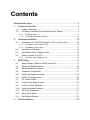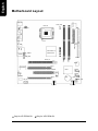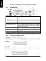
1
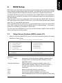
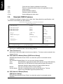
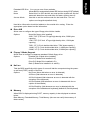
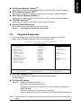
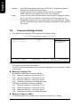
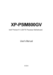
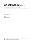
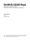
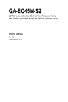
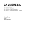
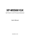
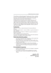
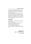
XP-P5CM-GV/
XP-P5CM-GL
Intel® Pentium® 4 LGA775 Processor Motherboard
User's Manual
M-050501
Copyright Declaration
© 2005 Gigatrend Technology Co., Ltd. All rights reserved. No part of this manual may be
reproduced, copied, translated, or transmitted in any form or by any means without express
permission from Gigatrend Technology. Companies and product names mentioned in this
document are trademarks or registered trademarks of their respective owners.
Legal Disclaimer
The information and content of this document is provided "as is", without warranty of any kind,
express or implied, including but not limited to the warranties of merchantability, fitness for a
particular purpose and non-infringement. Gigatrend Technology assumes no responsibility for
errors or omissions in this document or other documents which are referenced by or linked to
this document. The content of this document are subject to change without prior notice.
Gigatrend Technology may make improvements and/or changes in the product described in
this publication at any time and without prior notice. In no event shall Gigatrend Technology be
liable for any special, incidental, indirect or consequential damages of any kind arising out of
or in connection with the use or performance of this document. If you are uncertain about any
installation procedures, please consult a qualified computer technician.
Terms of Use
To avoid unnecessary errors of operation, please consult the user manual prior to hardware
installation. For more up-to-date information, please link to our company website at http://
www.axper.com.tw
Prior to beginning installation procedures, please make sure that your computer turned off and
is connected to a grounded power outlet. If your system is not turned off during installation,
this could result in harm or damage to the motherboard, the components as well as to the
user.
Motherboard
XP-P5CM-GV/XP-P5CM-GL
Motherboard
XP-P5CM-GV/XP-P5CM-GL
May 25, 2005
May 25, 2005
Contents
Motherboard Layout ......................................................................... 4
1. Product Introduction .................................................................. 5
1.1.
Feature Summary ............................................................................. 5
1.2.
I/O Back Panel and Connectors&Jumper Setting ........................... 6
1.2.1. I/O Back Panel ....................................................................................... 6
1.2.2. Connectors&Jumper Setting ................................................................ 6
2.
Hardware Installation ............................................................... 10
2.1.
Installation of a LGA775 Pentium 4 CPU and Fan Sink ................ 10
2.1.1. Installation of a LGA775 CPU ............................................................ 10
2.1.2. Installation of Fan Sink ....................................................................... 11
2.2.
Installation of Memory..................................................................... 12
2.3.
Installation of the Graphics Card ................................................... 13
2.4.
What is Axper's G.E.A.R.? ............................................................... 13
2.4.1. Graphics Card Support List ............................................................... 13
3.
BIOS Setup ............................................................................ 17
3.1.
Setup Screen Features (BIOS version:F1) .................................... 17
3.2.
Standard CMOS Features .............................................................. 18
3.3.
Advanced BIOS Features ............................................................... 20
3.4.
Integrated Peripherals .................................................................... 21
3.5.
Power Management Setup ............................................................ 23
3.6.
PnP/PCI Configuration ................................................................... 24
3.7.
PC Health Status ............................................................................ 25
3.8.
Frequency/Voltage Control ............................................................. 26
3.9.
Load Fail-Safe Defaults ................................................................. 27
3.10. Load Optimized Defaults ................................................................ 27
3.11.
Set User Password ........................................................................ 27
3.12. Save & Exit Setup ............................................................................ 27
3.13. Exit Without Saving.......................................................................... 27
4.
Driver Installation ..................................................................... 28
IT8712F
KB_MS
CPU_FAN
COM1
LGA775
FDD
VGA
LPT
ATX_12V
ATX
Intel 915GV j/
Intel 915GLk
SUR_CEN
SYS_FAN
DIMM1
IDE1
PCIE_16
DIMM2
AUDIO
F_AUDIO
XP-P5CM
LAN
USB
R_USB
BIOS
RTL8100C
PCI1
ICH6
GLk
GEAR
-GV j /
English
Motherboard Layout
SATA2
SATA0
CODEC
PCI2
CD_IN
F_USB1
Only for XP-P5CM-GV.
4
Only for XP-P5CM-GL.
BAT
CLR_CMOS
PWR_LED
F_PANEL
English
1.
Product Introduction
The user manual provides steps related to quick installation. If you wish to view complete
",open User Manual button located on the driver
product information, please select the "
CD or link to our website at http://www.axper.com to received the most up-to-date information.
1.1.
Feature Summary
CPU
Chipset
Memory
Slots
On-Board IDE
On-Board Floppy
On-Board SATA
On-Board Peripherals
On-Board LAN
On-Board VGA
On-Board Sound
BIOS
I/O Control
Hardware Monitor
Form Factor
LGA775 for Intel® Pentium® 4 Processor
Intel® Pentium® 4 533/800MHz FSB
L2 cache depends on CPU
North Bridge: Intel® 915GV /GL
South Bridge: Intel ® ICH6
2 184-pin DDR DIMM sockets, supports up to 2GB DRAM (Max.)
Supports dual channel DDR400/DDR333 DIMM
Supports only 2.5V DDR SDRAM
1 PCI Express x 16 slot device support *
1 GEAR slot device support
2 PCI slots support 33MHz & PCI 2.2 compliant
1IDE controller provides IDE HDD/CD-ROM with PIO, Bus Master
(Ultra DMA33/ATA66/ATA100) operation modes
Can connect up to 2 IDE devices
1 Floppy port supports 2 FDD with 360K, 720K,1.2M, 1.44M and
2.88M bytes
2 Serial ATA ports
1 Parallel port supports Normal/EPP/ECP mode
1 Serial port (COM1), 1 VGA port
6 USB 2.0/1.1 ports (4 x Rear, 2 x Front by cable)
1 Front Audio connector
1 PS/2 Keyboard
1 PS/2 Mouse
Built-in RTL8100C chip
1 RJ45 port
Built-in Intel® 915GV /GL chipset
ALC655 CODEC
Supports 2/4/6 channel
Line Out / Line In / Mic In
CD In
Licensed AWARD BIOS
Supports BIOSNow!
IT8712F
CPU/System fan revolution detect
CPU/System fan fail warning
CPU temperature detect
System voltage detect
Micro ATX size form factor, 23.6cm x 24.3cm
* PCI Express x 16 card runs up to x 4 mode
Only for XP-P5CM-GV.
Only for XP-P5CM-GL.
5
English
1.2.
I/O Back Panel and Connectors&Jumper Setting
1.2.1.
I/O Back Panel
Parallel Port
PS/2 Mouse
LAN
Line In
USB
Line Out
MIC In
PS/2 Keyboard
COM1
PS/2 Keyboard
PS/2 Mouse connector
Parallel port (LPT)
COM1 (Serial port)
VGA port
USB
(Universal Serial Bus Port)
LAN (RJ45 LAN Port)
Line In
Line Out
MIC In
1.2.2.
VGA
USB
Connects PS/2 standard keyboard and PS/2 standard
mouse
Connects to printer
Connects to serial-based mouse or data processing devices
Connects to 15-pin D-Sub device such as a monitor
Prior to use, please make sure that your system as well
as the connected attachments support the USB interface.
If driver installation is required, please consult the USB
section of the user manual.
Internet connection with speed of up to10/100Mbps
Connects to optical devices, CD players and other audio
input devices
Connects to speakers or headphones
Connects to microphone
Connectors&Jumper Setting
FDD (Floppy Disk Drive Connector)
The FDD connector is able to connect a single floppy disk drive via a FDD cable. Usually one
edge of the FDD cable is marked in red, please attach this marked edge to position 1 on the
connector.
2
34
1
33
IDE (IDE Connector)
The IDE connector is able to connect two IDE devices via an IDE cable and requires checking
of the IDE jumper setting.
6
2
40
1
39
The cooler fan power connector supplies a +12V power voltage via a 3-pin/4-pin(only for CPU_FAN)
power connector and possesses a ful-proof connection design.
Most coolers are designed with color-coded power connector wires. A red power connector wire indicates a positive connection and requires a +12V power voltage. The black connector wire is the
ground wire (GND).
Please remember to connect the power to the cooler to prevent system overheating and failure.
Caution!
Please remember to connect the power to the CPU fan to prevent CPU overheating and failure.
PIN
1
1
CPU_FAN
SYS_FAN
SIGNAL
1
GND
2
+12V
3
4
Sense
Speed Control (Only for CPU_FAN)
ATX_12V (+12V Power Connector)
The ATX_12V power connector provides power to the CPU. If this connector is not Attached,
the system will not start.
PIN
SIGNAL
1
GND
3
4
2
GND
1
2
3
4
+12V
+12V
ATX (ATX Power Connector)
The ATX power connector provides power to the motherboard. Prior to connection, please
make sure that the power supply is disconnected.
PIN
13
1
24
SIGNAL
PIN
SIGNAL
1
2
3.3V
3.3V
13
14
3.3V
-12V
3
GND
15
GND
4
+5V
16
PS_ON (soft on/off)
5
6
GND
+5V
17
18
GND
GND
7
GND
19
GND
8
Power Good
20
-5V
9
10
5V SB (stand by +5V)
+12V
21
22
+5V
+5V
11
+12V
23
+5V
12
3.3V (only for 24-pin ATX)
24
GND
12
PWR_LED
Connects to the system power LED indicator whereby the power is indicated as ON or OFF.
However, the indicator will flash when the system is suspended.
PIN
1
SIGNAL
1
2
MPD+
MPD-
3
MPD-
7
English
CPU_FAN (CPU Fan Power Connector); SYS_FAN (System Fan Power Connector)
SPK-
SPK+
MSG+
MSGPW+
PW-
The F_Panel Control Connector connects to certain connectors on the front panel of the
system casing such as IDE Hard Disk Active LED, speaker, reset, and power on/off connectors.
You can use the schematic diagram below as the basis for connection.
2
1
20
19
HD+
HDRESRES+
NC
English
F_PANEL (Front Panel Control Connector)
PIN
SIGNAL
HD
IDE Hard Disk Active LED
SPK
RES
Speaker Connector
Reset Switch
PW
Soft Power Connector
MSG
Message LED/Power/Sleep LED
NC
NC
SATA0/SATA2 (Serial ATA Connector, controlled by ICH6)
The SATA0/2 connector is able to connect a single Serial ATA device via a SATA cable.
For the connected SATA hard disk to work correctly, please check the related BIOS setting
and install proper driver for the SATA controller.
PIN
1
1
7
SIGNAL
GND
2
TXP
3
TXN
4
GND
PIN
SIGNAL
5
RXN
6
7
RXP
GND
F_AUDIO (Front Audio Connector)
Connects to the audio connector located on the front panel of the system casing
(dependent on case design). When use of the front panel audio connector is required,
please remove the 5-6 pin, 9-10 pin jumper.
Please note that use of only the front panel audio connector or the rear panel audio connector
is permitted.
PIN
10
9
2
1
SIGNAL
6
Rear Audio (R)
7
Reserved
3
MIC_BIAS
4
POWER
8
9
NO PIN
Front Audio (L)
5
Front Audio (R)
10
Rear Audio (L)
Connects CD-ROM or DVD-ROM audio connector.
PIN
8
SIGNAL
MIC
GND
CD_IN (Optical Drive Audio Connector)
1
PIN
1
2
SIGNAL
1
2
CD_L
GND
3
GND
4
CD_R
Connects to the USB connector located on the front panel of the system casing (dependent on
case design). Note: Please make sure that each USB connection matches its designated
position. If connections are made incorrectly, the result can lead to inability to use the function
or even damage.
PIN
SIGNAL
PIN
SIGNAL
9
1
10
2
1
POWER
6
USB Dy+
2
3
POWER
USB Dx-
7
GND
4
USB Dy-
8
9
GND
NO PIN
5
USB Dx+
10
NC
SUR_CEN (Surround Center Connector)
Please contact the place of purchase for the optional SUR_CEN cable.
PIN
SIGNAL
6
5
1
2
SUR OUTL
SUR OUTR
2
1
3
GND
4
No Pin
5
6
CENTER_OUT
BASS_OUT
CLR_CMOS (Clear CMOS)
You can clear the motherboard CMOS with the jumper to return your system to its initial
status. To prevent improper usage, the jumper does not include the jumper plug. If you wish
to use the Clear CMOS function, please short circuit the 1-2 Pin.
1
Open : Normal
1
Short : Clear CMOS
BAT(Battery)
The improper removal of the battery can result in harm. When replacing a
battery, please make sure you use one that is of similar brand and model
number.
For information related to battery specifications and precautions, please refer
to the manufacturer instructions.
If you wish to delete the data stored in the CMOS, please follow the steps
below:
1. Please turn off your computer and unplug the power.
2. Remove the battery from the motherboard.
3. Wait 10 minutes and then replace the battery onto the motherboard.
4. Plug in the power supply and turn on your system.
9
English
F_USB1 (Front USB Connector)
English
2.
Hardware Installation
1. Please make sure that the CPU used is supported by your motherboard.
2. Please be aware of the placement position of the CPU. If the CPU does not
insert properly, do not apply force but check the placement position.
3. Please make sure that an even layer of heat sink paste is added between the
CPU and the fan sink.
4. Please do not turn on the power prior to installing the fan sink. Doing so can
result in overheating and lead to permanent damage to the CPU.
5. Please follow the CPU specifications when setting the frequency. It is not
recommended that system speed settings exceed that of hardware
specifications. If you wish to set your system speed to exceed the recom
mended specifications, please check your hardware specifications eg: CPU,
graphics card, memory, hard drive
The following must be supported to allow the use of Hyper-Threading Technology:
- an Intel Pentium 4 CPU with HT
- a motherboard supporting HT
- HT selection feature within BIOS
- an operating system supporting HT
2.1.
Installation of a LGA775 Pentium 4 CPU and Fan Sink
2.1.1.
Installation of a LGA775 CPU
1. Push the socket lever arm down and away from the CPU
socket and raise it up completely.
2. Open the load plate and gently remove the plastic cover.
3. Hold the CPU with your thumb and index fingers (do not
touch the bottom of the CPU when holding it).
Align notchs on the two sides of the CPU with the small
sockets of the CPU socket and place the CPU straight
down.
10
2.1.2.
Installation of Fan Sink
1. Apply a thin coating of thermal paste to complete cover
the surface of the CPU.
2. Align the four fasteners of the fan sink with the four holes
around the CPU socket. Push down each fastener and
you should hear a "click" when the fastener is attached.
Make sure the four fasteners are attached securely.
Prior to installation of the fan sink, check the direction of
each fastener by the arrow engraved on fastener top.
Before attaching the fasteners, turn each fastener
clockwise. To uninstall the fan sink, release each fastener
by rotating the fastener along the direction of the arrows
and pull them up.
3. Connect the 4-wire power cable of the fan sink to the
CPU_FAN header on the motherboard to complete the
installation.
11
English
4. Make sure the CPU is properly installed and then close
the load plate. Lower the socket lever and engage it to
lock the CPU in place.
English
2.2.
Installation of Memory
1. Before installing or removing memory, please make sure that the computer power
is turned off to prevent hardware damage.
2. Please make sure that the memory used is supported by the motherboard.
3. Memory modules have a foolproof insertion design. The memory can be in
stalled only when facing the correct position. If you cannot insert the module,
please switch directions.
4. It is recommended that memory of similar capacity, specifications and brand be
used.
The motherboard supports DIMM memory modules, whereby BIOS will automatically detect
memory capacity and specifications. Memory modules are designed so that they can be
inserted only in one direction.
1. Unfasten the clips on each end of the memory slots.
Correctly align the memory module in the slot and
push downwards..
2. Once the memory module is correctly inserted, the
clips will automatically refasten. If the memory
module is positioned in the wrong direction, it will
not insert. If this occurs, please switch directions.
12
Installation of the Graphics Card
To install or remove an AGP graphics card,
first pull out the white GEAR knob before
insertion or removal. Releasing the GEAR
knob will hold the graphics card firmly in
place.
2.4.
What is Axper's G.E.A.R.?
The revolutionary and innovative G.E.A.R. (GIGABYTE Enhance AGP Riser) interface provides an additional interface for traditional AGP Graphics card on Intel chipset based PCI
Express solution motherboard. It supports most of the AGP Graphics card available in the
market from AGP 4X to AGP 8X graphics cards.
Note the following Information Before Use
1) Remove the sticker on the G.E.A.R. slot before inserting your AGP graphics card.
2) G.E.A.R. interface is designed to provide a temporary AGP solution before the mass
availability of PCI Express graphics card. It is suggested to use PCI Express X 16
interface graphics card to avoid the damage of your AGP graphics card.
3) G.E.A.R. interface is created through PCI interface signal and voltage switching to AGP
interface, due to this technical specification difference, it might cause AGP graphics
card life-span shortens.
4) Please view the graphics cards support list currently validated by Axper engineers.
2.4.1.
Graphics Card Support List
(The items below are all supported under the Windows XP operating system.
When using an add-on graphics card, please first delete the onboard graphics
driver before installing the driver for the add-on graphics card.)
Figure 1-1. 4X AGP Card
Graphics Chip
Nvidia
Maker
Gigabyte
Gigabyte
Gigabyte
Gigabyte
Gigabyte
Gigabyte
Model Name
GA-620
GA-622
GA-660 Plus
GA-GF2560
GA-GF2000
GA-GF1280
To be continued...
13
English
2.3.
1. Before installing the graphics card, please carefully read the accompanying user manual.
As well, make sure the computer power is turned off.
2. If you install a PCI Express x 16 card and wish to remove it, please gently press the latch
to release the card as the picture below shows before removal.
English
Figure 1-2. 4X AGP Card
Graphics Chip
Nvidia
ATi
SiS
Savage
Maker
Gigabyte
Gigabyte
Gigabyte
Gigabyte
Gigabyte
Gigabyte
ELSA
ELSA
ELSA
ELSA
Leadtek
Leadtek
Leadtek
Gigabyte
Gigabyte
Gigabyte
Gigabyte
Gigabyte
Gigabyte
Prolink
ASUS
Model Name
GV-GF2010D
GA-GF3000D
GV-GF1280-32E
GV-GF1280T-32P
GV-GF3200TF
GV-GF3500TF-GH
Gladiac Ultra
Gladiac 517
Gladiac 517vivo
Gladiac 525 A128
WinFast A170 TH
WinFast A250 TO
WinFast A250 Ultra
GV-AR64DL-T-SI
GV-AR64S-H
GV-AP64D
GV-AP64DH
GV-AP128DG-H
GV-AF128D-GH
SiS315 64MB
V3500
Maker
Gigabyte
Gigabyte
ASUS
ASUS
ASUS
MSI
MSI
Leadtek
Leadtek
Albatron
Gigabyte
Gigabyte
Gigabyte
Gigabyte
Gigabyte
Gigabyte
Triplex
Power Color
Model Name
GV-N57L128D
GV-N59X128D
V9180TD
V9480-TVD
V9520
MX440-VTD8X MS-8888
Ti4600-TD-8X
WinFast A280LE TD
WinFast A310 TD
NVIDIA 5950
GV-R9700 Pro
GV-R9700
GV-R9500
GV-R9200C3
GV-R98P128D
GV-R92P128VH
Xabre Pro
Xabre 600 Pro
Figure 2. 8X AGP Card
Graphics Chip
Nvidia
ATi
SiS
To be continued...
14
English
Figure 3. PCI Express x16 Card
Graphics Chip
Nvidia
ATi
Maker
Gigabyte
Gigabyte
Gigabyte
Gigabyte
Gigabyte
Gigabyte
Gigabyte
Gigabyte
Gigabyte
Gigabyte
Gigabyte
ASUS
Gigabyte
Gigabyte
Gigabyte
Gigabyte
Gigabyte
Gigabyte
Gigabyte
Gigabyte
ASUS
ASUS
MSI
Model Name
GV-NX53128D
GV-NX57128D
GV-NX59128D
GV-NX62128D
GV-NX66256D
GV-NX66T128VP
GV-NX66T128D
GV-NX68T256DH
GV-NX55128DP
GV-NX68U256D
GV-NX62TC256D
EN6600/TD/128
GV-RX30S128D
GV-RX60P128D
GV-RX60X128V
GV-RX70128D
GV-RX70P128D
GV-RX80T256V
GV-RX80L256V
GV-RX80256D
AX800XT
AX700PRO
RX600 XT-TD128
For the most up-to-date information related to graphics card support, please link to our
website at http://www.axper.com
15
16
English
English
3.
BIOS Setup
BIOS (Basic Input and Output System) stores all the information of the motherboard settings
that is needed for system initiation within the CMOS. The CMOS SETUP utility allows the user
to make changes in BIOS configurations that are required or to activate certain features.
The CMOS SETUP saves each item configuration in the CMOS SRAM of the motherboard.
When the power is turned off, the battery on the motherboard supplies the required power to
the CMOS SRAM.
When the power is turned on, pushing the <Del> button during the BIOS POST (Power-On
Self Test) will bring up the CMOS SETUP screen. If you wish to enter the BIOS setup, please
press "Ctrl + F1" at the BIOS setup screen.
When using BIOS setup for the first time, it is recommended that you save the present BIOS
onto a disk in case you need to reset the BIOS back to its original settings. If you wish to
update to a new BIOS, the "BIOSNow!" can be used.
The user can select "BIOSNow!" as a way to quickly and easily update or back up BIOS
without entering the operating system.
3.1.
ø
Setup Screen Features (BIOS version:F1)
When you enter the CMOS SETUP screen, you will see the following screen and setting
selections as shown below.
CMOS Setup Utility-Copyright (C) 1984-2005 Award Software
}
}
Standard CMOS Features
Advanced BIOS Features
Load Fail-Safe Defaults
Load Optimized Defaults
}
}
Integrated Peripherals
Power Management Setup
Set Supervisor Password
Set User Password
}
}
PnP/PCI Configurations
PC Health Status
Save & Exit Setup
Exit Without Saving
}
Frequency/Voltage Control
ESC: Quit
F8: BIOSNow!
higf: Select Item
F10: Save & Exit Setup
Time, Date, Hard Disk Type...
Instructions
< , , , ,Enter>
<Page Up,Page Down>
<Esc>
<F1>
<F2>
<F5>
Movement in all four directions to highlight a desired option,
pressing <Enter> will select the option and take you to its
appropriate screen
Used to toggle up and down the available options for a
particular item, whereby <Page Up> can also be used to
increase value option and <Page Down> to decrease
value option
Return to main setup screen or exit setup
Gives the list of options available for each item
Gives the list of options available for the current item
Returns settings to previous values (not applicable to main setup
screen)
17
English
<F6>
<F7>
Gives the list of options available for each item
Return to Optimized default values (not applicable to main
setup screen)
Enters BIOSNow! feature
Displays system information
Saves settings and exits setup
<F8>
<F9>
<F10>
3.2.
Standard CMOS Features
ø Includes the settings for items such as date, time, floppy disk drive specifications, and
hard drives connected to the IDE interface.
CMOS Setup Utility-Copyright (C) 1984-2005 Award Software
Standard CMOS Features
}
}
}
}
Date (mm :dd:yy)
Time (hh:mm :ss)
Fri, Jan 9 2005
22:31:24
IDE Channel 0 Master
IDE Channel 0 Slave
IDE Channel 2 Master
IDE Channel 2 Slave
[None]
[None]
[None]
[None]
Drive A
Drive B
Floppy 3 Mode Support
[1.44M, 3.5"]
[None]
[Disabled]
<Month>
Jan. to Dec.
Halt On
[All, But Keyboard]
Base Memory
Extended Memory
Total Memory
640K
127M
128M
<Day>
1 to 31 (or maximum
allowed in the month)
higf: Move
Enter: Select
F5: Previous Values
+/-/PU/PD: Value
F10: Save
F6: Fail-Safe Defaults
Item Help
Menu Level}
Change the day, month,
year
<Week>
Sun. to Sat.
<Year>
1999 to 2098
ESC: Exit
F1: General Help
F7: Optimized Defaults
n Date (mm:dd:yy)
Allows you to setup the date in the mm:dd:yy fashion.
n Time (hh:mm:ss)
Allows you to set up the date in the hh:mm:ss fashion. The time must be entered in the
24-hour format.
n IDE Channel 0 Master(Slave) [IDE Device Setup]
IDE HDD Auto-Detection Press "Enter" to select this option for automatic device
detection.
IDE Channel 0 Master(Slave) You can use one of three methods:
Auto
Allows BIOS to automatically detect IDE devices during POST(default)
None
Select this if no IDE devices are used and the system will skip the
automatic detection step and allow for faster system start up.
Manual
User can manually input the correct settings
Access Mode Use this to set the access mode for the hard drive. The four
options are:CHS/LBA/Large/Auto(default:Auto)
n IDE Channel 2 Master(Slave)
[IDE Device Setup]
IDE HDD Auto-Detection Press "Enter" to select this option for automatic device
detection.
18
Hard drive information should be labeled on the outside drive casing. Enter the
appropriate option based on this information.
n Drive A/B
Allows user to configure the type of floppy drive his/she installs.
Options:
None (No floppy drive installed)
360K, 5.25" (5.25 inch PC-type high-density drive; 360K bytes
capacity.)
1.2M, 5.25" (5.25 inch AT-type high-density drive; 1.2M bytes
capacity.)
720K, 3.5" (3.5 inch double-sided drive; 720K bytes capacity.)
1.44M, 3.5" (3.5 inch double-sided drive; 1.44M bytes capacity.)
2.88M, 3.5" (3.5 inch double-sided drive; 2.88M bytes capacity.)
n Floppy 3 Mode Support
Allows user to configure a Japanese standard 3 Mode floppy drive.
Options:
Disabled (No 3 Mode drive installed)
Drive A (3 Mode Drive installed in A:)
Drive B (3 Mode Drive installed in B:)
Both (3 Mode Drive installed in A: and B:)
n Halt on
Tells the BIOS specifically which types of errors will halt the computer during the poweron self test (POST) section of the boot.
Options:
No Errors (Never halt when an error is detected)
All Errors (Halt whenever an error is detected)
All, But Keyboard (Halt whenever an error is detected with the
exception of the keyboard)
All, But Diskette (Halt whenever an error is detected with the ex
ception of the diskette)
All, But Disk/Key (Halt whenever an error is detected with the
exception of the diskette and keyboard) (default:All, But Keyboard)
n Memory
When BIOS is displayed during POST, memory capacity is also displayed as shown
below:
Base Memory, Extended Memory, Total Memory (the user can verify the accuracy of
these values)
19
English
Extended IDE Drive You can use one of two methods:
Auto
Allows BIOS to automatically detect IDE devices during POST(default)
None
Select this if no IDE devices are used and the system will skip the
automatic detection step and allow for faster system start up.
Access Mode
Use this to set the access mode for the hard drive. The two
options are:Large/Auto(default:Auto)
English
3.3.
ø
Advanced BIOS Features
Allows the configuration of advanced settings such as boot sequence, password
check, etc.
CMOS Setup Utility-Copyright (C) 1984-2005 Award Software
Advanced BIOS Features
} Hard Disk Boot Priority
[Press Enter]
Item Help
First Boot Device
[Floppy]
Menu Level}
Second Boot Device
[USB-FDD]
Third Boot Device
[Hard Disk]
Select Hard Disk Boot
Password Check
[Setup]
Device Priority
#
CPU Hyper-Threading
[Enabled]
Limit CPUID Max. to 3
[Disabled]
No-Execute Memory Protect (Note)
[Enabled]
CPU Enhanced Halt (C1E) (Note)
[Enabled]
CPU Thermal Monitor 2(TM2) (Note)
[Enabled]
CPU EIST Function (Note)
[Enabled]
On-Chip Frame Buffer Size
[8MB]
higf: Move
Enter: Select
F5: Previous Values
+/-/PU/PD: Value
F10: Save
F6: Fail-Safe Defaults
ESC: Exit
F1: General Help
F7: Optimized Defaults
" # " If the installed CPU is an Intel Pentium 4 CPU supporting Hyper-Threading Technology,
the system will automatically provide this option.
n Hard Disk Boot Priority
The user can select the boot order for hard disks connected to onboard IDE, SATA,
SCSI, RAID controllers or other add-on cards.
n First / Second / Third Boot Device
The user can select the order in which the system will boot.
Options:
Floppy, LS120, Hard Disk, CDROM, ZIP,USB-FDD, USB-ZIP, USBCDROM, USB-HDD, LAN, Disabled
n Password Check
Allows user to set a password. To remove the password entry requirement, enter
SETUP and make sure there is no entry and then press <Enter>.
Options:
System (Password entry is required during system start up and to enter
CMOS SETUP)
Setup (Password entry is required to enter CMOS SETUP)(default:Setup)
n CPU Hyper-Threading
Allows user to enable the CPU Hyper-Threading function, of which must also be sup
ported by the operating system. (default: Enabled)
n Limit CPUID Max. to 3
This option will be available when you install an Intel Prescott processor.
Enable this item when you install old operating systems (example:NT 4.0)
(default: Disabled)
(Note) If the installed CPU supports this function, the system will automatically provide this
option.
20
Allows user to enable the No-Execute Memory Protect function. (default: Enabled)
n CPU Enhanced Halt (C1E) (Note)
Allows user to enable the CPU Enhanced Halt (C1E) function. (default: Enabled)
n CPU Thermal Monitor 2(TM2) (Note)
Allows user to enable the CPU Thermal Monitor 2(TM2) function.(default: Enabled)
n CPU EIST Function (Note)
Allows user to enable the CPU EIST function.(default: Enabled)
n On-Chip Frame Buffer Size
Allows user to set the size of the on-chip frame buffer.
Options:
1MB/4MB/8MB/16MB/32MB (default:8MB)
3.4.
ø
Integrated Peripherals
This menu allows you to control the various ports of the computer such as IDE,
SATA, USB, IEEE1394, COM port, LPT port, AC97 audio, etc.
CMOS Setup Utility-Copyright (C) 1984-2005 Award Software
Integrated Peripherals
On-Chip Primary PCI IDE
[Enabled]
Item Help
On-Chip SATA Mode
[Enhanced]
Menu Level}
x PATA IDE Set to
Ch.0 Master/Slave
If a hard disk
SATA Port 0/2 Set to
Ch.2 Master/Slave
controller card is
USB Controller
[Enabled]
used, set at Disabled
USB 2.0 Controller
[Enabled]
USB Keyboard Support
[Disabled]
[Enabled]
USB Mouse Support
[Disabled]
Enable onboard IDE
AC97 Audio
[Auto]
PORT
Onboard H/W LAN
[Enabled]
OnBoard LAN Boot ROM
[Disabled]
[Disabled]
Onboard Serial Port 1
[3F8/IRQ4]
Disable onboard IDE
Onboard Parallel Port
[378/IRQ7]
PORT
Parallel Port Mode
[SPP]
x ECP Mode Use DMA
3
higf: Move
Enter: Select
F5: Previous Values
+/-/PU/PD: Value
F10: Save
F6: Fail-Safe Defaults
ESC: Exit
F1: General Help
F7: Optimized Defaults
n On-Chip Primary PCI IDE
Allows the user to enable or disable the first onboard IDE channel.
(default:Enabled)
n On-Chip SATA Mode
Options:
Disabled (Disable this function.)
Auto (BIOS will detect automatically)
Combined (Support up to 4 hard drives: Two for SATA ports and two for
PATA IDE ports)
Enhanced (Allow up to 4 hard drives to be used)
Non-Combined (SATA will be configured to PATA mode)(default:Enhanced)
(Note) If the installed CPU supports this function, the system will automatically provide this
option.
21
English
n No-Execute Memory Protect (Note)
English
n PATA IDE Set to
Options:
Ch.0 Master/Slave, Ch.1 Master/Slave
(default:Ch.0 Master/Slave )
n SATA Port 0/2 Set to
This value depends on the settings of "On-Chip SATA Mode" and "PATA IDE Set to". For
example, if you set PATA IDE to Ch. 1 Master/Slave, this option will be automatically set to
Ch. 0 Master/Slave.
n USB Controller
Allows the user to enable or disable the onboard USB controller. (default:Enabled)
n USB 2.0 Controller
Allows the user to enable or disable the onboard USB2.0 (default:Enabled)
n USB Keyboard Support
Allows user to use a USB-based keyboard (Enable if you are using a USB keyboard,
otherwise Disable) (default:Disabled)
n USB Mouse Support
Allows user to use a USB-based mouse (Enable if you are using a USB mouse,
otherwise Disable) (default:Disabled)
n AC97 Audio
Allows the user to use the onboard AC97 audio (default:Auto)
n Onboard H/W LAN
Allows the user to enable or disable the onboard LAN (default:Enabled)
n OnBoard LAN Boot ROM
Allows user to enable or disable booting from a network drive (default:Disabled)
n Onboard Serial Port 1
Allows the user to enable or disable the first onboard serial port
Options:
Auto, 3F8/IRQ4, 2F8/IRQ3, 3E8/IRQ4, 2E8/IRQ3, Disabled (default:3F8/IRQ4)
n Onboard Parallel Port
Allows the user to enable or disable the onboard parallel port.
Options:
378/IRQ7, 278/IRQ5, 3BC/IRQ7, Disabled (default:378/IRQ7)
n Parallel Mode
Use this to select the operation mode for the parallel port.
Options:
SPP, EPP, ECP, EPP+ECP (default:SPP)
n ECP Mode Use DMA
Allows the user to select the ECP Mode Use DMA
Options:
1, 3, Disabled (default:3)
22
ø
English
3.5.
Power Management Setup
This is used to control the various power saving features of the PC.
CMOS Setup Utility-Copyright (C) 1984-2005 Award Software
Power Management Setup
[S1(POS)]
Item Help
[Instant-Off]
Menu Level}
[Enabled]
[S1]
[Enabled]
Set suspend type to
[Disabled]
Power On Suspend under
Everyday
ACPI OS
0:0 :0
[Disabled]
[S3]
[Disabled]
Set suspend type to
Enter
Suspend to RAM under
[Soft-Off]
ACPI OS
ACPI Suspend Type
Soft-Off by PWR-BTTN
PME Event Wake Up
ModemRingOn
Resume by Alarm
x Date (of Month) Alarm
x Time (hh:mm :ss) Alarm
Power On by Mouse
Power On by Keyboard
x KB Power ON Password
AC BACK Function
higf: Move
Enter: Select
F5: Previous Values
+/-/PU/PD: Value
F10: Save
F6: Fail-Safe Defaults
ESC: Exit
F1: General Help
F7: Optimized Defaults
n ACPI Suspend Type
Allows user to select the Advanced Configuration and Power Interface(ACPI) as S1/
POS (Power On Suspend) or S3/STR(Suspend To RAM) (default:S1/POS)
n Soft-Off by PWR-BTTN
Controls whether the PC shuts off immediately after hitting the power button or delaying
a few seconds. (default:Instant-Off)
Options:
Instant-off (PC shuts off immediately)
Delay 4 Sec. (PC shuts off after a 4-sec. delay)
n PME Event Wake Up
Allows user to select the Power Management Event (PME) wake up function which
requires the system to have a +5VSB power supply using a rate of 1A or less.
(default:Enabled)
n ModemRingOn
To use this feature, an Ethernet card supporting the PCI2.2 or newer standard must be
used. (default:Enabled)
n Resume by Alarm
If set to Enabled, the user can set the date and time for automatic system power-on.
(default:Disabled)
Settings:
Date (of Month) Alarm :
Everyday, 1~31
Time (hh: mm: ss) Alarm : (0~23) : (0~59) : (0~59)
n Power On by Mouse
Allows user to turn on system using the mouse. (default:Disabled)
n Power On By Keyboard
Allows user to turn on system using the keyboard. (default:Disabled)
23
English
n KB Power ON Password
Allows user to set a 1-5 character long password for powering on the keyboard. Select
Enter to complete setting.
n AC BACK Function
Allows user to select system status when power is removed and returned.
Options:
Memory (return prior to power removal)
Full-On (return to full system power)
Soft-Off (use of Soft PWR button to power on system)(default:Soft-Off)
3.6.
ø
PnP/PCI Configuration
This menu allows you to configure your PCI slots. You can assign IRQ's for various PCI
slots.
CMOS Setup Utility-Copyright (C) 1984-2005 Award Software
PnP/PCI Configurations
PCI 1 IRQ Assignment
[Auto]
Item Help
PCI 2 IRQ Assignment
[Auto]
Menu Level}
PCI 3 IRQ Assignment
[Auto]
Device(s) using this
INT:
Simple COMM. Cntrlr
- Bus 0 Dev30 Func 3
higf: Move
Enter: Select
F5: Previous Values
+/-/PU/PD: Value
F10: Save
F6: Fail-Safe Defaults
ESC: Exit
F1: General Help
F7: Optimized Defaults
n PCI 1 IRQ Assignment
Allows you to assign an IRQ for the first PCI slot. Options: Auto,3,4,5,7,9,10,11,12,14,
15 (default:Auto)
n PCI 2 IRQ Assignment
Allows you to assign an IRQ for the second PCI slot. Options: Auto,3,4,5,7,9,10,11,12,
14,15 (default:Auto)
n PCI 3 IRQ Assignment
Allows you to assign an IRQ for the third PCI slot. Options: Auto,3,4,5,7,9,10,11,12,14,
15 (default:Auto)
24
ø
English
3.7.
PC Health Status
This menu displays the current CPU temperature, the fan speeds, voltages etc.
CMOS Setup Utility-Copyright (C) 1984-2005 Award Software
PC Health Status
Vcore
OK
Item Help
DDR25V
OK
Menu Level}
+3.3V
OK
+12V
OK
Current CPU Temperature
45°C
Current CPU FAN Speed
4440 RPM
Current SYSTEM FAN Speed
0 RPM
CPU Warning Temperature
[Disabled]
CPU FAN Fail Warning
[Disabled]
SYSTEM FAN Fail Warning
[Disabled]
CPU Smart FAN Control
[Enabled]
CPU Smart FAN Mode
[Auto]
higf: Move
Enter: Select
F5: Previous Values
+/-/PU/PD: Value
F10: Save
F6: Fail-Safe Defaults
ESC: Exit
F1: General Help
F7: Optimized Defaults
n Current Voltage(V) Vcore / DDR25V / +3.3V / +12V
Automatically checks system voltage
n Current CPU Temperature
Automatically checks CPU temperature
n Current CPU / SYSTEM FAN Speed (RPM)
Automatically checks CPU/SYSTEM fan speed
n CPU Warning Temperature
If CPU temperature exceeds the temperature users select, alarm will occur. (default:
Disabled)
Options:
60oC / 140oF
70oC / 158oF
80oC / 176oF
90oC / 194oF
Disabled
n CPU / SYSTEM FAN Fail Warning
Allows users to enable or disable the CPU/System Fan Fail Warning function. (default:
Disabled)
n CPU Smart FAN Control
Allows users to enable or disable the CPU Smart FAN Control function. (default:
Enabled) With this item set to enabled, CPU fan changes speed depending on CPU
temperature.
n CPU Smart FAN Mode
Allows users to set the CPU Smart FAN mode when CPU Smart FAN Control is set to
Enabled. (default: Auto)
25
English
Options:
Note:
3.8.
ø
Auto (BIOS autochecks which type of CPU fan is installed and sets the
optimcal CPU Smart FAN control mode.)
Voltage (Set this item to Voltage if a 3-pin CPU fan is installed.)
PWM (Set this item to PWM if a 4-pin CPU fan is installed.)
In fact, you can set the CPU Smart Fan Control mode to Voltage for either 3pin or 4-pin CPU fan. However, for those 4-pin CPU fans that are not
designed following Intel's 4-wire fans PWM control specifications, setting
the CPU Smart Fan Control mode to PWM may not effectively reduce the CPU
fan speed.
Frequency/Voltage Control
This allows user to configure CPU frequency and voltage settings.
CMOS Setup Utility-Copyright (C) 1984-2005 Award Software
Frequency/Voltage Control
CPU Clock Ratio
[15X]
Item Help
Memory Frequency For
[Auto]
Menu Level}
Memory Frequency (Mhz)
266
Set CPU Ratio if CPU
Ratio is unlocked
higf: Move
Enter: Select
F5: Previous Values
+/-/PU/PD: Value
F10: Save
F6: Fail-Safe Defaults
ESC: Exit
F1: General Help
F7: Optimized Defaults
n CPU Clock Ratio
Allows user to set the CPU Clock Ratio.
If the CPU used locks this feature, then it will not be displayed or will not function. (based
on CPU type)
n Memory Frequency For
for FSB(Front Side Bus) frequency=533MHz,
2.50
Memory Frequency = Host clock X 2.50.
3.00
Memory Frequency = Host clock X 3.00.
4.00
Memory Frequency = Host clock X 4.00.
Auto Set Memory frequency by DRAM SPD data.
for FSB(Front Side Bus) frequency=800MHz,
1.66
Memory Frequency = Host clock X 1.66.
2.00
Memory Frequency = Host clock X 2.00.
2.66
Memory Frequency = Host clock X 2.66.
Auto Set Memory frequency by DRAM SPD data.
n Memory Frequency (Mhz)
The memory frequency is based on the " Memory Frequency For" setting.
26
ø
Save & Exit Setup
To save any changes you made to the BIOS you must choose this option. The
system will automatically exit setup and perform a system restart. Pushing <F10>
will have the same effect.
Push <Y> and <Enter> to save and exit setup. If you do not wish to save, select <N> or
<Esc> to return to the main menu.
3.13.
ø
Set User Password
Use this to set the password that is needed to either enter into the BIOS or to boot the
system. Entering in a blank field will disable the password.
Please input an 8 character long password and then select Enter. You will be required
to re-enter the password for confirmation. If you wish to remove the need for password
entry, leave the entry blank and then select Enter. BIOS will then display "PASSWORD
DISABLED". Once you have completed the password setting, you will need to go to
"Advanced BIOS Features" and select "Password Check" for setup of password check.
3.12.
ø
Load Optimized Defaults
Like the Fail-Safe mode above, this option loads the BIOS default settings, but runs the
system at optimal performance.
Please select <Y> and <Enter> to load optimized defaults.
3.11.
ø
Load Fail-Safe Defaults
Use this option to reset your BIOS settings to the system defaults. You should only use
this if you are encountering serious problems.
Please select <Y> and <Enter> to load Fail-Safe defaults. Once this is loaded, your
system may be slowed since this uses a minimal performance setting to allow stable
system running.
3.10.
ø
English
3.9.
Exit Without Saving
Use this option instead of the one above if you wish to exit the BIOS without saving the
changes you have made. Pushing <ESC> will have the same effect.
Push <Y> and <Enter> to exit setup. You can return to the main menu by pushing <N>or
<Esc>.
27
English
4.
Driver Installation
Driver installation for the Windows 2000/XP operating systems is simple. Once you insert
the provided driver disks into your optical drive, the AUTORUN screen will appear. If this
screen does not appear, you can use "D:\setup.exe" (with "D" being the specified drive) to
bring up the screen shown below. Just follow the screen instructions to easily complete
driver installation.
Open User Manual
Display system information
Open Readme File
Browse CD
Contact Us
axper Install -Displays required driver installation, select "Go" for
automatic installation
Customize Installation - Allows specific choice of drivers for installation
axper Utilities - Displays axper's unique utilities
Software - Displays the required software
28