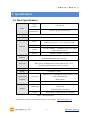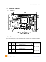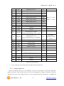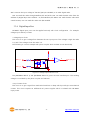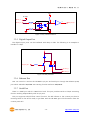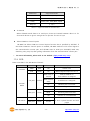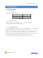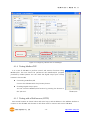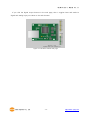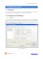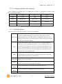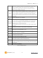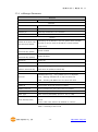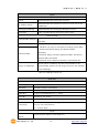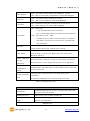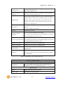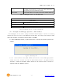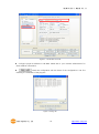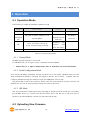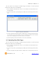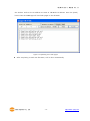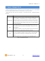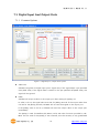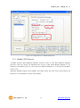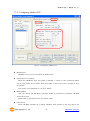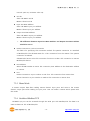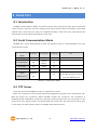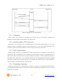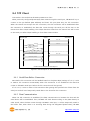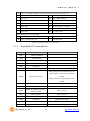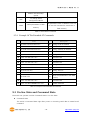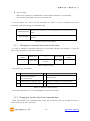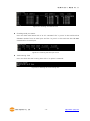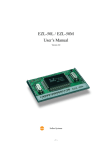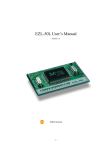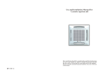
1
Modular I/O Device Server CIE-M10 User’s Manual Version 1.1 2009-07-01 Sollae Systems http://www.sollae.co.kr CIE-M10 User’s Manual Ver. 1.1 1 Contents 1 CONTENTS ...............................................................................................................................- 1 - 2 PRODUCT BRIEFS ....................................................................................................................- 5 2.1 Introduction .......................................................................................................................................................... - 5 2.2 Components ......................................................................................................................................................... - 5 - 3 SPECIFICATION ........................................................................................................................- 6 3.1 Brief Specification .............................................................................................................................................. - 6 3.2 Hardware Interface ............................................................................................................................................ - 7 - 3.2.1 Dimension .................................................................................................................................................... - 7 3.2.2 JP1 Port ......................................................................................................................................................... - 7 3.2.3 Analog Input Port ..................................................................................................................................... - 8 3.2.4 Digital Input Port ...................................................................................................................................... - 9 3.2.5 Digital Output Port ............................................................................................................................... - 10 3.2.6 Ethernet Port ............................................................................................................................................ - 10 3.2.7 Serial Port .................................................................................................................................................. - 10 3.2.8 LED ............................................................................................................................................................... - 11 4 GETTING STARTED .............................................................................................................. - 13 4.1 Test Operation .................................................................................................................................................. - 13 - 4.1.1 PC „s IP Address ..................................................................................................................................... - 13 4.1.2 Installing CIE-M10 ................................................................................................................................. - 13 4.1.3 Configuring CIE-M10 ........................................................................................................................... - 13 4.1.4 Testing Modbus/TCP ............................................................................................................................ - 14 4.1.5 Testing with a Web browser (HTTP) ............................................................................................. - 14 5 CONFIGURING PARAMETERS ............................................................................................ - 16 5.1 Parameters ......................................................................................................................................................... - 16 5.2 Configuring with ezManager ..................................................................................................................... - 16 - 5.2.1 ezManager ................................................................................................................................................ - 16 5.2.2 Configuring Method with ezManager ......................................................................................... - 17 5.2.3 ezManager Buttons............................................................................................................................... - 17 5.2.4 ezManager Parameters ....................................................................................................................... - 19 5.2.5 Example of ezManager Operation – MAC Address............................................................... - 23 6 OPERATION ........................................................................................................................... - 25 6.1 Operation Mode .............................................................................................................................................. - 25 - Sollae Systems Co., Ltd. -1- http://www. eztcp.com CIE-M10 User’s Manual Ver. 1.1 6.1.1 Normal Mode .......................................................................................................................................... - 25 6.1.2 Serial Configuration Mode ................................................................................................................ - 25 6.1.3 ISP Mode ................................................................................................................................................... - 25 6.2 Uploading New Firmware ........................................................................................................................... - 25 6.3 Uploading New Web Pages ....................................................................................................................... - 26 7 INPUT / OUTPUT PORTS .................................................................................................... - 28 7.1 Digital Input And Output Ports ................................................................................................................ - 29 - 7.1.1 Common Options .................................................................................................................................. - 29 7.2 Modbus/TCP ...................................................................................................................................................... - 30 - 7.2.1 Introduction .............................................................................................................................................. - 30 7.2.2 Standard Modbus/TCP ........................................................................................................................ - 30 7.2.3 Modbus/TCP Protocol ......................................................................................................................... - 31 7.2.4 Configuring Modbus/TCP .................................................................................................................. - 32 7.2.5 Mater Mode ............................................................................................................................................. - 33 7.2.6 Serialized Modbus/TCP ....................................................................................................................... - 33 7.3 Macro Mode...................................................................................................................................................... - 34 - 7.3.1 Introduction .............................................................................................................................................. - 34 7.3.2 Operators................................................................................................................................................... - 34 7.3.3 Operand ..................................................................................................................................................... - 34 7.3.4 Example of Equation ............................................................................................................................ - 35 7.4 Web (HTTP) ........................................................................................................................................................ - 37 - 7.4.1 Configuring Web Function ................................................................................................................ - 37 7.4.2 Security ....................................................................................................................................................... - 38 7.4.3 User Web Page ....................................................................................................................................... - 38 8 SERIAL PORT ........................................................................................................................ - 39 8.1 Introduction ....................................................................................................................................................... - 39 8.2 Serial Communication Mode ..................................................................................................................... - 39 8.3 TCP Server .......................................................................................................................................................... - 39 - 8.3.1 Connection ............................................................................................................................................... - 40 8.3.2 Serial Data Before TCP Connection ............................................................................................... - 40 8.3.3 Data Communication ........................................................................................................................... - 40 8.3.4 Terminating Connection ..................................................................................................................... - 40 8.4 TCP Client ........................................................................................................................................................... - 41 - 8.4.1 Serial Data Before Connection ........................................................................................................ - 41 8.4.2 Data Communication ........................................................................................................................... - 41 8.4.3 Terminating Connection ..................................................................................................................... - 42 8.4.4 DNS .............................................................................................................................................................. - 42 Sollae Systems Co., Ltd. -2- http://www. eztcp.com CIE-M10 User’s Manual Ver. 1.1 8.5 AT Command .................................................................................................................................................... - 42 8.6 UDP ....................................................................................................................................................................... - 43 9 AT COMMAND MODE ........................................................................................................ - 45 9.1 Introduction ....................................................................................................................................................... - 45 9.2 AT Command Format .................................................................................................................................... - 45 - 9.2.1 Basic Command Format ..................................................................................................................... - 45 9.2.2 Basic Response Format ....................................................................................................................... - 45 9.2.3 Basic AT Commands ............................................................................................................................. - 45 9.2.4 Example of Basic AT Commands .................................................................................................... - 46 9.2.5 Expanded AT Command Set ............................................................................................................. - 47 9.2.6 Example Of The Extended AT Commands ................................................................................. - 48 9.3 On-line State and Command State ........................................................................................................ - 48 - 9.3.1 Changing to Command State from On-line State ................................................................. - 49 9.3.2 Changing to On-line State from Command State ................................................................. - 49 9.4 TCP Connection ............................................................................................................................................... - 50 - 9.4.1 Active Connection – Client................................................................................................................ - 50 9.4.2 Passive Connection – Server ............................................................................................................ - 50 9.5 TCP Disconnection .......................................................................................................................................... - 50 - 9.5.1 Active Disconnection ........................................................................................................................... - 51 9.5.2 Passive Disconnection ......................................................................................................................... - 51 10 ADDITIONAL FUNCTIONS .................................................................................................. - 52 - 10.1 Security Function............................................................................................................................................. - 52 - 10.1.1 Password .................................................................................................................................................... - 52 10.1.2 Access Control with MAC Address ................................................................................................ - 52 10.1.3 Access Control with IP Address ...................................................................................................... - 52 10.1.4 Access Control from ezManager .................................................................................................... - 52 10.1.5 Disabling Security Functions ............................................................................................................ - 52 10.2 Managing TCP Sessions ............................................................................................................................... - 53 - 10.2.1 How To Disconnect TCP Sessions .................................................................................................. - 53 10.3 IP Address Notification Function ............................................................................................................. - 54 10.4 Telnet Function ................................................................................................................................................. - 54 - 10.4.1 Commands For Telnet Console ....................................................................................................... - 54 11 TECHNICAL SUPPORT/WARRANTY /PRECAUTIONS..................................................... - 56 - 11.1 Technical Support ........................................................................................................................................... - 56 11.2 Warranty .............................................................................................................................................................. - 56 - 11.2.1 Refund ......................................................................................................................................................... - 56 Sollae Systems Co., Ltd. -3- http://www. eztcp.com CIE-M10 User’s Manual Ver. 1.1 11.2.2 Free A/S...................................................................................................................................................... - 56 11.2.3 Charged A/S ............................................................................................................................................. - 56 11.3 Precautions......................................................................................................................................................... - 56 12 MODIFICATION HISTORY OF THIS DOCUMENT ............................................................ - 58 - Sollae Systems Co., Ltd. -4- http://www. eztcp.com CIE-M10 User’s Manual Ver. 1.1 2 Product Briefs 2.1 Introduction The need for the data communication system via Internet is rapidly increasing due to the development of Internet. In order to send and receive data via Internet, TCP/IP protocol must be used. Any machines that need an Internet connection must implement TCP/IP protocol. In order for any device to implement TCP/IP protocol, the machine must either be able to implement TCP/IP protocol by itself, have an open TCP/IP source implanted, or must use an OS that is capable of implementing the protocol. However, the above options require a great deal of time, cost, and effort to make it work. CIE-M10 uses Modbus/TCP and HTTP to provide users with ability to control and monitor remote digital output ports and analog/digital input ports. Therefore, with CIE-M10, remote I/O ports can easily be controlled and monitored at the same time. Also, CIE-M10 provides the Macro functions to change automatically the output port values based on the value of input ports. Not only that CIE-M10 can control and monitor digital I/O ports, it also provides with functions that can covert the serial data to TCP/IP data and vice versa. Therefore, one CIE-M10 can perform numerous functions at the same time. Along with its strong TCP/IP/UDP functions, CIE-M10 also provides DHCP and PPPoE functions to be used in cable and xDSL networks. And it has DDNS (Dynamic DNS) function, so it can be used more easily in the internet. It is also equipped with online debugging functions that will allow the users to quickly respond to the problems that might occur during the installation. 2.2 Components CIE-M10 body Sollae Systems Co., Ltd. -5- http://www. eztcp.com CIE-M10 User’s Manual Ver. 1.1 3 Specification 3.1 Brief Specification Input 3.3V (±10%) Voltage Power Current 190 mA @ 3.3V without load Consumption Size 64.4 mm x 40 mm x 17 mm Weight about 17 g Digital Input Ports – 8 Ports (3.3V CMOS) Input Interface Analog Input Ports – 1 Port with 10bits ADC Output Digital Output Ports – 8 Port (3.3V CMOS) 1 x UART (300bps ~ 230400bps) with 3.3V CMOS Serial RTS/CTS Flow Control Network 10Base-T/100Base-TX (RJ45) Ethernet 10/100M bits auto-sense Network Auto MDI/MDX(cable auto sensing) TCP, UDP, IP, ICMP, ARP, DHCP, PPPoE, Telnet Protocols DNS lookup, DDNS(Dynamic DNS), Modbus/TCP, HTTP RFC2217(Telnet COM Port Control Option) Debugging Online debugging function RoHS Compliant to RoHS Modbus/TCP – Slave/Master, Passive/Active, Serial Communicati I/O Ports Web browser(HTTP) Macro Mode on Mode Serial Port TCP Server/Client, AT emulation, UDP Configuration Utility through LAN or Serial Utilities ezManager Socket Test Firmware/HTML uploading ezVSP Virtual Serial – TCP/IP Driver for Windows Table 3-1 Brief Specification Firmware and Utility can be downloaded from our website. (http://www.eztcp.com) Sollae Systems Co., Ltd. -6- http://www. eztcp.com CIE-M10 User’s Manual Ver. 1.1 3.2 Hardware Interface 3.2.1 Dimension Figure 3-1 CIE-M10‟s Dimension 3.2.2 JP1 Port JP1 is a user interface which is not populated by any connecters to be connected to user device with user‟s conector. The pitch is 2.54mm. # Name Description Dir. 1 DI0 Digital Input Port 0 In 2 DI1 Digital Input Port 1 In 3 DI2 Digital Input Port 2 In 4 DI3 Digital Input Port 3 In 5 DI4 Digital Input Port 4 In 6 DI5 Digital Input Port 5 In 7 DI6 Digital Input Port 6 In Sollae Systems Co., Ltd. -7- Etc. Min VIL= -0.3V Max VIL= 0.8V Min VIH= 2.0V Max VIH= 5.5V http://www. eztcp.com CIE-M10 User’s Manual Ver. 1.1 8 DI7 Digital Input Port 7 In 9 DO0 Digital Output Port 0 Out 10 DO1 Digital Output Port 1 Out 11 DO2 Digital Output Port 2 Out 12 DO3 Digital Output Port 3 Out Min VOH = 2.9V, 13 DO4 Digital Output Port 4 Out Max VOL = 0.4V 14 DO5 Digital Output Port 5 Out 15 DO6 Digital Output Port 6 Out 16 DO7 Digital Output Port 7 Out 17 GND Ground − 18 GND Ground − 19 ADVREF 20 ADC_IN0 ADC Reference Voltage In (Input Voltage Range: 2.6V ~ 3.3V) 10bit ADC Analog Input Port 0 In (Input Voltage Range: 0V~ADVREF) Conversion Time: 2.33us 21 RXD Receive Data In 22 CTS Clear To Send In 23 TXD Transmit Data Out 24 RTS Request To Send Out 25 RESET- Reset(Active Low) In 26 ISP- 27 VCC Power Input (DC 3.3V) − 28 VCC Power Input (DC 3.3V) − 29 GND Ground − 30 GND Ground − ISP Mode: Low when it boots up (Internally pulled-up, Active Low) In Table 3-2 JP1 Specification 4 pin connector (JP2) will be removed after the first production. 3.2.3 Analog Input Port There is an analog input port in the CIE-M10. This port is connected to 10 bits ADC (Analog to Digital Converter). User should input 2.6V~3.3V to the ADVREF for reference voltage of the ADC. ADC_IN0 port is for user‟s analog sensors, its input voltage should be between 0V ~ ADVREF. The Sollae Systems Co., Ltd. -8- http://www. eztcp.com CIE-M10 User’s Manual Ver. 1.1 ADC converts the input voltage of the ADC_IN0 (0V~ADVREF) to 0~1023 digital value. User can read this value through Modbus/TCP and HTTP. User can read the ADC value from the address of (Digital Input Port Address + 4) with Modbus/TCP. When user read the ADC value with a web browser, user can read this value with $a0 variable. 3.2.4 Digital Input Port CIE-M10‟s digital input ports can be applied variously with circuit configuration – for example: voltage input and Dry-Contact. • Voltage Input Circuit This circuit is to get a voltage from between the two input ports. If the voltage is high the value is 1, and if the voltage is low the value is 0. The following is a circuit example with photo-coupler which isolates circuits electrically. 3.3V INPUT_1 INPUT_2 1 1K( 1/4W) 2 CIE_M10_DI 1K( 1/4W) Figure 3-2 Voltage Input Interface Circuit The [EXTERNAL INPUT 1] and [EXTERNAL INPUT 2] ports are user interface port. The working voltage is concluded by the photo-coupler and resistors. • Dry-Contact Circuit This circuit is to get a signal from mechanical switches or relays which provide just a mechanical contact. This circuit requires an additional DC power supplier which is isolated with CIE-M10‟s input power. Sollae Systems Co., Ltd. -9- http://www. eztcp.com CIE-M10 User’s Manual Ver. 1.1 3.3V DC PWR INPUT_A 1 INPUT_B 2 1K( 1/4W) CIE_M10_DI 1K( 1/4W) Figure 3-3 Dry-Contact Interface 3.2.5 Digital Output Port The digital output ports can be interfaced with relays or SSR. The following is an example to interface to relays. VC C CIE_M10_DO OU TPU T_1 OU TPU T_2 Figure 3-4 Relay Interface 3.2.6 Ethernet Port User can control or monitor the CIE-M10‟s I/O port and serial port through the Ethernet (LAN) port which embeds 10M/100M auto-sensing function and auto MDI/MDIX. 3.2.7 Serial Port There is a UART port which is CMOS-3.3V level. This port provides serial to TCP/IP converting function working independently with its I/O ports. This port supports RTS/CTS flow control function. The RTS informs to the counter part that its receiving buffer is free and is ready to get data. And the CIE-M10 gets CTS information from the counter part‟s RTS. Sollae Systems Co., Ltd. - 10 - http://www. eztcp.com CIE-M10 User’s Manual Ver. 1.1 Parameters Supported Values Baud rate 300 ~ 230,400 bps Data bits 8, 7, 6, 5 Parity None, Even, Odd, Mark, Space Stop bit 1, 1.5, 2 Table 3-3 Supported Values of the Serial Port TX Interval When CIE-M10 sends data to its serial port, there are intervals between data. It is for slow serial devices to give it enough time to process. The unit is byte. Telnet COM Port Control Option CIE-M10 has Telnet COM Port Control Option function that is specified by RFC2217. If the Telnet COM Port Control Option is enabled, CIE-M10 sends the CTS control signal to the communication counter part, and CIE-M10 sets its serial port items(RTS, Baud rate, data bits, parity, stop bit) after getting information from the communication counter part. For more information, please refer to our website. (http://www.eztcp.com) 3.2.8 LED There are 4 LEDs in the CIE-M10 as followed. Mode Common Name Color Status Description PWR Red On Power is on Do0 Green On When Digital Output Port 0 is 1 Blink every 1 Static IP address or second An IP address is assigned. STS_ACT Yellow Normal Mode LINK_ACT ISP Mode Green Blink 4 times every On Modbus/TCP Connected Blink Transmitting data to LAN On LAN link is established Blink Receiving data from LAN Off LAN link is not established When CIE-M10 is in the ISP mode STS_ACT Yellow Off LINK_ACT Green On/Off Sollae Systems Co., Ltd. IP address isn‟t assigned. - 11 - in which upload firmware and web pages http://www. eztcp.com CIE-M10 User’s Manual Ver. 1.1 Serial Configuration Mode STS_ACT Yellow LINK_ACT Green Blink every 1 CIE-M10 is in the ISP mode which second Configures CIE-M10 through the On/Off serial port Table 3-4 LEDs Sollae Systems Co., Ltd. - 12 - http://www. eztcp.com CIE-M10 User’s Manual Ver. 1.1 4 Getting Started 4.1 Test Operation 4.1.1 PC ‘s IP Address Change PC‟s IP addresses as followed: IP Address 10.1.0.2 Subnet Mask 255.0.0.0 Gateway IP address - Table 4-1 PC IP 4.1.2 Installing CIE-M10 CIE-M10‟s operating voltage is DC 3.3V. You have to use a stable power supplier. Then the green LED of the RJ45 connector will blink. 4.1.3 Configuring CIE-M10 Using ezManager, change the settings of CIE-M10. Click [Search All] button on the ezManager window. Then, ezManager will search for every ezTCP on the local network. When there is no found device, click [Windows Firewall] button on the ezManager window to check for firewall setting. If this setting is ON, the ezManager could not perform the search. When CIE-M10 is found, the MAC address of CIE-M10 will be shown on the [Search List] window. (The MAC address is also written on the bottom of the product case.) To configure it clearly, please press [Factory Reset] button to reset it with initial values. Sollae Systems Co., Ltd. - 13 - http://www. eztcp.com CIE-M10 User’s Manual Ver. 1.1 Figure 4-1 Configuring CIE-M10 with an ezManager 4.1.4 Testing Modbus/TCP It is a test of CIE-M10 to perform control and monitor functions using Modbus/TCP. This test should be performed with Modbus/TCP program provided by Sollae Systems. You can check the digital output port 0 easily because it has an LED. Connecting a Modbus/TCP Connect the CIE-M10 with the [Connect] button. Checking Digital Output ports You can check the Modbus/TCP function by pressing the buttons in the “I/O Port”. Figure 4-2 Testing Modbus/TCP . 4.1.5 Testing with a Web browser (HTTP) Start a web browser as shown below and write http:// and IP address in the address window to connect to the CIE-M10 web browser. It will allow users to monitor and control CIE-M10. Sollae Systems Co., Ltd. - 14 - http://www. eztcp.com CIE-M10 User’s Manual Ver. 1.1 If you click the digital output buttons in the web page, then it toggles those and sends its digital and analog input port values to the web browser. Figure 4-3 CIE-M10‟s default web page Sollae Systems Co., Ltd. - 15 - http://www. eztcp.com CIE-M10 User’s Manual Ver. 1.1 5 Configuring Parameters 5.1 Parameters To communicate with TCP/IP, user should set IP address related parameters. All parameters including IP address are set by ezManager which is supplied by Sollae Systems. 5.2 Configuring with ezManager 5.2.1 ezManager The parameters of CIE-M10 (IP address, I/O ports, serial port and etc) can be configured by an application utility for Windows, ezManager. ezManager operates in Windows platform (Windows 98, 98SE, 2000, ME, XP, Vista). The following window is the window that pops up when the user starts ezManager for the first time. Figure 5-1 ezManager Sollae Systems Co., Ltd. - 16 - http://www. eztcp.com CIE-M10 User’s Manual Ver. 1.1 5.2.2 Configuring Method with ezManager There are [MAC], [IP], [Serial] tabs in the ezManager according to configuration method. Please refer to the following table. MAC IP Serial Media LAN LAN Serial Method UDP Broadcast UDP Unicast Serial Port Identification MAC Address IP Address COM Port Properties UDP port 50005 UDP Port 50005 115200/N/8/1 Table 5-1 Configuration Method with ezManager 5.2.3 ezManager Buttons The followings are descriptions about buttons in the ezManager. Search for all ezTCP series (including CIE-M10) connected to the local network. The MAC addresses of each ezTCP will be shown on the Search All [Search Results] box. (The MAC address of CIE-M10 is written on the bottom of the product.) The setting values of each ezTCP will be shown on right side of [Search Results]. Input 6 digit number written on the CIE-M10 to the MAC ADDRESS input box or Input CIE-M10‟s IP address in the IP address category on Read the IP tab. This will allow for the user to read setting parameters for a specific CIE-M10. When there are too many ezTCPs connected to the network and it is hard to find a desired ezTCP from the LIST box, this button may be conveniently used. After changing the settings, save the changes to ezTCP. CIE-M10 will Write automatically reset after the save. Therefore, pressing this button may cause system shutdown during normal use. View Comment Open Read (Serial) Write (Serial) Set If this check box is checked, ezManager displays CIE-M10‟s nick name which is set in the Comment. To read CIE-M10‟s parameters through serial port, open a serial port which is connected to the CIE-M10 in advance. Reading parameters from CIE-M10 through the serial port. Writing parameters to CIE-M10 through the serial port. CIE-M10 provides user authentication function in order to prevent other Sollae Systems Co., Ltd. - 17 - http://www. eztcp.com CIE-M10 User’s Manual Ver. 1.1 Password people from changing its settings. The authentication process is done using a password and this button will allow users to change the password. This password will be used when connected to the web (HTTP). The ID is „admin‟ in this case. User can check the status of CIE-M10 during its operation. When the button is clicked, a new window will pop up and show operation time, Status current IP address, data amount via serial port and other information. Double-Clicking each devices of the [Search List] will also yield the same information. Factory Reset Resetting parameters of the CIE-M10 This will be used to read debugging messages from CIE-M10. In order to use this function, activate [Debugging Message] option under [Option] Debugging Message tab. When the debugging is over, please deactivate the [Debugging Message] option to reduce network load. The debugging messages are transmitted to the LAN in shape of UDP broadcast. Change F/W HTML Export Variables Import Variables Multi Write PING/ARP Simple Test Windows Firewall Exit uploading new firmware or new html files in the ISP mode Exporting the current parameters to a file Importing a saved file to ezManager Configuring multiple CIE-M10s Doing ping tests and managing ARP table Doing tests of serial to TCP/IP converting function. When the PC‟s firewall is activated, ezManager may not be operated properly. By clicking this button, the user can easily check their Windows firewall status. Terminating the ezManager. Table 5-2 ezManager Buttons Sollae Systems Co., Ltd. - 18 - http://www. eztcp.com CIE-M10 User’s Manual Ver. 1.1 5.2.4 ezManager Parameters Network Product Product name and firmware version Network Local IP Address CIE-M10‟s IP Address Subnet Mask Subnet Mask of the network Gateway IP Gateway IP Address of the network DNS IP Address Name Server‟s IP Address Option Obtain an IP From The First Received Packet Obtain an IP Automatically (DHCP) Obtain an IP Automatically (PPPoE) Obtaining an IP address in the first packet after CIE-M10 booted up and is used as CIE-M10‟s Local IP Address temporarily DHCP Enabled PPPoE Enabled PPPoE ID PPPoE ID PPPoE Password PPPoE Password Obtain DNS Server When CIE-M10 gets IP addresses by DHCP or PPPoE, it gets Address Automatically DNS server IP address automatically. Notify IP Change DDNS(dyndns.org) – Using DDNS service of DynDNS Protocol TCP – Sending CIE-M10‟s IP to the host with TCP UDP – Sending CIE-M10‟s IP to the host with UCP Interval Interval to send IP address information (Unit: Minute) DDNS ID Account ID: when the Protocol is DDNS DDNS Password Account Password: when the Protocol is DDNS Port TCP or UDP port of the host (Protocol: TCP or UDP) Data Type Data Format (ASCII/HEX) (Protocol: TCP or UDP) DDNS: CIE-M10‟s host name which is registered in the DDNS Host Name(custom) server TCP or UDP: Host name or IP address to connect Table 5-3 ezManager Network Tab Sollae Systems Co., Ltd. - 19 - http://www. eztcp.com CIE-M10 User’s Manual Ver. 1.1 Option Option Telnet Enable/Disable the Telnet login function Enable/Disable the IP Search Function in the IP tab of the IP Address Search ezManager Debugging Message Enable/Disable the Debugging Message Function Comment User Comment about the product (nick name) ezTCP Firewall Allowed MAC Address Only the host having the MAC address can connect to the CIE-M10 Only the hosts having IP address range can connect to the Allowed IP Range CIE-M10. The range is calculated by making bitwise AND between Allowed IP Range and Network Mask. (Example) Network Mask Allowed IP Range: 192.168.1.1,Network Mask: 255.255.0.0 Bitwise AND: 192.168.0.0 Allowed IP hosts‟ address: 192.168.0.0~192.168.255.255 If this option is enabled, only the host specified in the Apply to ezManager Allowed MAC address and IP range can access the CIE-M10 with ezManager, Table 5-4 ezManager Option Tab Serial Port Serial Port Serial Type - Baudrate Baudrate (300bps∼230,400bps) Parity Parity (NONE, EVEN, ODD, MARK, SPACE) Data Bits Length of the Data Bits (5, 6, 7, 8 bits) Stop Bit Stop Bit (1, 1.5, 2 bits) Flow Flow Control (NONE, RTS/CTS) Interval between byte which outgoes from CIE-M10‟s the serial TX Interval Port for slow serial devices 0 ~ 25 (Unit: Byte) TCP/IP Communication Mode Sollae Systems Co., Ltd. Communication Mode of the Serial Port - 20 - http://www. eztcp.com CIE-M10 User’s Manual Ver. 1.1 Peer Address Peer Port Local Port COD – TCP Client: A host name or IP address to connect U2S – UDP: A host name of IP address to send UDP datagram COD – TCP Client: A port number to connect U2S – UDP: A port number to send UDP datagram T2S – TCP Server: Local port to listen on as a TCP server U2S – UDP: Local port to receive UDP datagram T2S – TCP Server: Event Byte - 0: ignores data before the connection - Not 0: stores data before the connection and transmits it COD – TCP Client or U2S – UDP: - CIE-M10 tries to a make a TCP connection or transmits UDP data if the byte from its serial port is greater than this parameter Timeout TCP connection will be disconnected if there‟s no data communication during the Timeout (Unit: second) CIE-M10 transmits data in its buffer if there‟s no incoming data Data Frame from its serial port during the Data Frame time. (Unit: 10ms, Minimum Value: 4) Telnet COM Port Control (RFC2217) Disable TCP Transmission Delay Create an ezVSP Port When this field is enabled, it sends not only serial port data but also serial port‟s control signal with telnet protocol. (RFC2217) CIE-M10 stops TCP nagle timer to reduce delay when it send data to the remote host. Creating a new virtual serial port for ezVSP with proper parameters. (Supporting ezManager from 2.0j and ezVSP from 2.2h) Table 5-5 ezManager Serial Tab I/O Port – Basic Settings Web(HTTP) Enable/Disable the web server to monitor and control the I/O ports with web browers Web(HTTP) Port Web server‟s port number (default: 80) Size of Web(HTTP) Size of user‟s web pages (80KB, 96KB, 112KB) Page 80KB is recommended Modbus/TCP Sollae Systems Co., Ltd. - 21 - http://www. eztcp.com CIE-M10 User’s Manual Ver. 1.1 Enable/Disable Modbus/TCP to monitor and control the I/O Modbus/TCP ports with Modbus/TCP Notify Input Port When its input port‟s value is changed, it sends response Change data without any master‟s query. Slave: When a master request a query to read and write, it outputs data its output port or sends its input port value Master/Slave Master: Write its input port data to the remote device‟s output ports. Reads the remote device‟s input port and reflects it its output port. Interval to sends queries to slave when it operates as a Poll Interval master (Unit: 1ms, Resolution: 10ms) Unit ID Modbus/TCP Unit ID Input Port Address (Reference Number) Input Port Base The difference between Input Port Base Address and Output Address Port Base Address should be over 8. Out Port Address (Reference Number) Out Port Base Address The difference between Input Port Base Address and Output Port Base Address should be over 8. Passive Connection Operates as a TCP server for Modbus/TCP Active Connection Operates as a TCP client for Modbus/TCP A host name or IP address to make a TCP connection for Peer Address Modbus/TCP Passive Connection: TCP port number to listen to Peer Port Active Connection: TCP port of the remote host to make a TCP connection Table 5-6 ezManager I/O Port – Basic Settings Tab I/O Port – I/O Port Option Digital Input Valid Time The input signal should keep during the Valid Time to recognize it. (Unit: 1ms, Resolution: 10ms) Digital Output Macro Enable/Disable the Macro function Do0 ~ Do7 Equations for macro function Sollae Systems Co., Ltd. - 22 - http://www. eztcp.com CIE-M10 User’s Manual Ver. 1.1 CIE-M10 outputs data to its output ports after [Delay] time Delay is expired. (Unit: 1ms, Resolution: 10ms) Initial State The initial values of its output ports when CIE-M10 boots up Table 5-7 ezManager I/O Port – I/O Port Option Tab I/O Port – I/O Port Comment Digital Input Di0 ~ Di7 Each digital input port name Digital Output Do0 ~ Do7 Each digital output port name Table 5-8 ezManager I/O Port – I/O Port Comment Tab 5.2.5 Example of ezManager Operation – MAC Address The ezManager can be used to change IP address related settings of ezTCP. The Following example will show you how to read CIE-M10‟s setting values and change those settings. Please follow this procedure to change the setting values of CIE-M10. When ezManager‟s [Read], or [Search All] button is clicked, the following window will pop up. Figure 5-2 Searching ezTCP If 1 or more ezTCP is found, MAC address will be shown in the ezManager‟s [Search Result] box. Check to make sure that the MAC address shown in the [Search Result] window is as same as the MAC address written on the product‟s sticker. If there‟s no response, check the firewall in your PC. Sollae Systems Co., Ltd. - 23 - http://www. eztcp.com CIE-M10 User’s Manual Ver. 1.1 Figure 1-3 A CIE-M10 is found Configure proper IP address to CIE-M10. Please ask to your network administrator for the IP address information. Check the configuration with this button if the configuration is OK. The following is a screenshot of the ping test. Figure 5-4 Ping test Sollae Systems Co., Ltd. - 24 - http://www. eztcp.com CIE-M10 User’s Manual Ver. 1.1 6 Operation 6.1 Operation Mode The following is a table of CIE-M10‟s operation mode. Mode How to enter Function Baudrate Normal ISP-: High or Open when it boots up Normal User defined Serial Configura ISP- Low for 20ms~1,000ms in the Normal Mode tion ISP Configuring the CIE-M10 through serial port 1. ISP- Low when it boots up 2. ISP- Low more than 1 second Uploading new firmware and 115,200bpsNone-8-1 – user‟s web page Table 6-1 ezTCP Operation Mode 6.1.1 Normal Mode CIE-M10 operates normally in this mode. If a CIE-M10‟s ISP- pin is high or open, it operates as Normal Mode. Please refer to “7. Input / Output Ports” and “8. Serial Port” for more information. 6.1.2 Serial Configuration Mode User can set CIE-M10‟s parameters through its serial port in this mode. CIE-M10 enters into the Serial Configuration Mode by inputting low signal to the ISP- pin for 20ms ~ 1,000ms. User can configure CIE-M10 through the serial port with the ezManager in this mode. The yellow LED of the RJ-45 connector blinks every 0.5 second and all security functions are disabled. So user can fix some problems because of security functions. 6.1.3 ISP Mode User can upload new firmware and user‟s web page in the ISP mode. If the ISP pin is low when the CIE-M10 boots up, it enters into the ISP mode. And if the ISP pin is low more than 1 second in the Normal Mode, it enters into the ISP mode as well. 6.2 Uploading New Firmware Sollae Systems Co., Ltd. - 25 - http://www. eztcp.com CIE-M10 User’s Manual Ver. 1.1 User can upload a new firmware to CIE-M10 through the Ethernet in the ISP mode with [Change F/W / HTML] menu in the ezManager. Run CIE-M10 as ISP Mode and connect it to the Ethernet. And press [Search All] to find the CIE-M10. After find the product, press [Change F/W / HTML] then the following windows will be open. Figure 6-1 Change F/W / HTML Window Select a firmware with [Open Firmware / HTML] button or drag new firmware and drop into the window. And set the IP address as same as CIE-M10‟s IP address. Press the [Send] button then the ezManager will send the firmware to the CIE-M10. After completing to send new firmware, it will re-boot automatically. 6.3 Uploading New Web Pages User can upload user‟s web pages to CIE-M10 through the Ethernet in the ISP mode with [Change F/W / HTML] menu in the ezManager. Run CIE-M10 as ISP Mode and connect it to the Ethernet. And press [Search All] to find the CIE-M10. After find the product, press [Change F/W / HTML] then the following windows will be open. Select web pages with [Open Firmware / HTML] button or drag and drop those into Sollae Systems Co., Ltd. - 26 - http://www. eztcp.com CIE-M10 User’s Manual Ver. 1.1 the window. And set the IP address as same as CIE-M10‟s IP address. Press the [Send] button then the ezManager will send web pages to the CIE-M10. Figure 6-2 Uploading user‟s web pages After completing to send new firmware, it will re-boot automatically. Sollae Systems Co., Ltd. - 27 - http://www. eztcp.com CIE-M10 User’s Manual Ver. 1.1 7 Input / Output Ports There are 8 digital input ports, 1 analog input port and 8 digital output ports in the CIE-M10. User should make hardware interfaces to the CIE-m10 for user own purpose. Those input and output ports are monitored or controlled three ways – Modbus/TCP, Macro, and HTTP. Method Description Modbus/TCP protocol is used to communicate with CIE-M10‟s I/O ports. When CIE-M10 is in Slave/Passive mode, it operates as a standard Modbus/TCP Modbus/TCP device. It can be operated as a master. A master outputs data after reading remote device‟s input ports and write to the remote device‟s output ports after reading its input ports. It can also establish TCP active connection. It is a mode that allows the users automatically controls output port‟s value based on input port status by setting Macro values prior to CIE- Macro M10 operation. During Macro operation, current status values may be read using HTTP or Modbus/TCP, but output values cannot be controlled. CIE-M10 can be controlled and monitored using web browsers. Connect to CIE-M10‟s IP address via web browser to access CIE-M10‟s HTTP control and monitor web page. This webpage shows current status values. User can upload user‟s own web pages into the CIE-M10 as well. Table 7-1 Controlling the I/O port Sollae Systems Co., Ltd. - 28 - http://www. eztcp.com CIE-M10 User’s Manual Ver. 1.1 7.1 Digital Input And Output Ports 7.1.1 Common Options Figure 7-1 Digital Input / Output Ports Option Valid Time CIE-M10 recognizes its digital input ports‟ signals only if the signal keeps a pre-specified time (Valid Time). If the signal doesn‟t remain for the pre-specified time(Valid Time), this signal will be ignored. Delay CIE-M10 will output a value to the output port after waiting for [Delay] ms. In order to do so, the signal value must last for [Delay] seconds. If the output value does not last for the [Delay] seconds, CIE-M10 will not send that signal to the output port. If the [Delay] value is set as 0, CIE-M10 will send the output value to the output port immediately. The [Delay] is used for Modbus/TCP, Macro, HTTP, and other functions provided by CIEM10. The unit used for the [Delay] is 1ms. However, since the accuracy is only guaranteed Sollae Systems Co., Ltd. - 29 - http://www. eztcp.com CIE-M10 User’s Manual Ver. 1.1 in 10ms, the designated values will round down in units of 10ms according to the designated values by the users Initial State User can set the initial state of the output ports. If it boots up, it sets the initial values to its output ports. 7.2 Modbus/TCP 7.2.1 Introduction Modbus was announced to control PLCs (Programmable Logic Controller) which are used widely for factory automation by Modicon. It is a de-facto standard in industrial automation market now. Modbus is divided by Master and Slave. Maters are usually programs which are working on the computers and slaves are usually devices which are controlled by masters. Modbus is a protocol which communicates through serial lines (RS232, RS422, and RS485). But as Ethernet devices are increasing, Modbus/TCP which communicates over TCP/IP network was released. 7.2.2 Standard Modbus/TCP Usually a master is a program which works on a computer and a slave is a device which is controlled by the master. If the master queries to the slave, the slave replies to the master. The following is an example how to configure the CIE-M10 for the standard Modbus/TCP. Sollae Systems Co., Ltd. - 30 - http://www. eztcp.com CIE-M10 User’s Manual Ver. 1.1 Figure 7-2 Configuration for standard Modbus/TCP 7.2.3 Modbus/TCP Protocol CIE-M10 supports Read Multiple Registers (Function Code: 3) and Write Multiple Registers (Function Code: 16) among the Modbus/TCP‟s function codes. Read Multiple Registers is for reading the CIE-M10‟s input port value and Write Multiple Registers is for writing the CIE-M10‟s output ports. Because CIE-M10 supports both Master and Slave mode and both active and passive TCP connection, it can adapted in various environments. Sollae Systems Co., Ltd. - 31 - http://www. eztcp.com CIE-M10 User’s Manual Ver. 1.1 7.2.4 Configuring Modbus/TCP Figure 7-3 Configuring Modbus/TCP Modbus/TCP CIE-M10‟s I/O ports are controlled by Modbus/TCP. Notify Input Port Change When the CIE-M10‟s input port state is changed, it inform to the connected master with a reply packet. This is useful when user wants to know input ports‟ change as soon as possible. This option is not standard so it is off in default. Master/Slave User can choose the CIE-M10‟s operation mode. To operate as a standard, CIE-M10 should be a slave. Please refer to following section for master mode.. Poll Interval When CIE-M10 operates as a master, CIE-M10 send queries to the slave every this Sollae Systems Co., Ltd. - 32 - http://www. eztcp.com CIE-M10 User’s Manual Ver. 1.1 interval. (Unit: ms, minimum value: 10) Unit ID Slave: CIE-M10‟s unit ID Master: Slave‟s unit ID Input Port Base Address Slave: CIE-M10‟s input port address Master: Slave‟s input port address Output Port Base Address Slave: CIE-M10‟s output port address Master: Slave‟s output port address The difference between Input Port Base Address and Output Port Base Address should be over 8. Passive Connection / Active Connection This field is for specifying TCP connection method. The passive connection is a standard of Modbus/TCP. The CIE-M10 waits for a TCP connection from the master if the passive connection is selected. CIE-M10 also has an active TCP connection function to make a TCP connection to remote Modbus/TCP device. Peer Address When CIE-M10 makes an active TCP connection, Peer Address is the destination address to connect. Port Passive Connection: A port number to wait for a TCP connection from remote host. Active Connection: A port number to make a TCP connection to remote host 7.2.5 Mater Mode A master outputs data after reading remote device‟s input ports and write to the remote device‟s output ports after reading its input ports. User can make a remote switch system with this mode. 7.2.6 Serialized Modbus/TCP CIE-M10‟s I/O port can be accessed through the serial port with Modbus/TCP. The data is as same as data over TCP of Modbus/TCP. Sollae Systems Co., Ltd. - 33 - http://www. eztcp.com CIE-M10 User’s Manual Ver. 1.1 To use this function, you have to set it as followed. Figure 7-4 Enabling Serialized Modbus/TCP 7.3 Macro Mode 7.3.1 Introduction CIE-M10 can operate by some macros (equations). CIE-M10 turns on or off automatically its output ports according to pre-defined equations. Check Macro check box in ezManager to activate CIE-M10 macro mode. 7.3.2 Operators The algorithm used in the Macro mode is Boolean Algebras. The AND, OR, NOT are used as operators. Parenthesis can also be used. The priority of operators is in the following order: parenthesis > NOT > AND > OR. Each operator is represented by the following symbols. Operator Symbol Parenthesis Open ( Parenthesis Close ) NOT / Description Since calculations within the parenthesis have the highest priority, they will be calculated first. Parenthesis may be nested used. Operand that follows NOT operator is toggled. If Operand values that surrounds AND operator all AND * 1, the result value will be 1. If either one of them is 0, the result will be 0 as well. If Operand values that surrounds OR operator all 0, OR + the result value will be 0. If either one of them is 1, the result will be 1 Table 7-2 Macro Operators 7.3.3 Operand Operands used in macro mode are each input port. Each input port is designated with i0 ~ i7 Sollae Systems Co., Ltd. - 34 - http://www. eztcp.com CIE-M10 User’s Manual Ver. 1.1 symbol based on their sequence. The operand is case-insensitive. 7.3.4 Example of Equation The following is a screenshot which has two equations. Figure 7-5 ezManager with Macro Equations In this case, the equations for two output port are as the following. Output Port Equation Do0 i0 + i1 Do2 i0 * /(i1 + i7) Description Perform OR for i0 and i1. Spaces in between two operands may be ignored Perform NOT with value after performing OR for i1 and i7. Then, perform AND with that value and i0 Table 7-3 Examples of Macro Equations Based on input values from three input ports, the output values are as the following. Output ports that equations are not applied will be maintained as 0 (OFF). Sollae Systems Co., Ltd. - 35 - http://www. eztcp.com CIE-M10 User’s Manual Ver. 1.1 Input Port Output Ports i0 i1 i7 Do0 Do1 Do2 Do3 Do4 Do5 Do6 Do7 0 0 0 0 0 0 0 0 0 0 0 0 0 1 0 0 0 0 0 0 0 0 0 1 0 1 0 0 0 0 0 0 0 0 1 1 1 0 0 0 0 0 0 0 1 0 0 1 0 1 0 0 0 0 0 1 0 1 1 0 0 0 0 0 0 0 1 1 0 1 0 0 0 0 0 0 0 1 1 1 1 0 0 0 0 0 0 0 Table 7-4 Output Ports Values According to Input Ports Value Sollae Systems Co., Ltd. - 36 - http://www. eztcp.com CIE-M10 User’s Manual Ver. 1.1 7.4 Web (HTTP) When HTTP check box in ezManager is selected, CIE-M10 input/output port values may be monitored and controlled using web browser. User can upload user‟s web pages into the CIE-M10 as well. 7.4.1 Configuring Web Function Figure 7-6 Enabling Web Function of the CIE-M10 Web(HTTP) User can monitor and control the CIE-M10‟s input and output ports with web server. Web(HTTP) Port The default web port is 80. But changing web port is required in some cases. To access to the specific web port with web browser, add a colon( and port number in the end of address in the web browser. Sollae Systems Co., Ltd. - 37 - http://www. eztcp.com CIE-M10 User’s Manual Ver. 1.1 (example) http://10.1.0.1:8080 Size of Web(HTTP) Page User can select user web page space size. But we are strongly recommend you to use 80KB because if you use others your web page might destroyed when you upload new firmware to the CIE-M10. 7.4.2 Security If you set a password with the [Set Password] button, you have to enter the password when you login with web page. The ID is „admin‟ in this case. Figure 7-7 Login CIE-M10 with a web server 7.4.3 User Web Page User can upload user specific web pages. For more information about it, please visit our web site‟s SUPPORT page. Sollae Systems Co., Ltd. - 38 - http://www. eztcp.com CIE-M10 User’s Manual Ver. 1.1 8 Serial Port 8.1 Introduction CIE-M10 provides RS232↔TCP/IP conversion function along with input/output port monitor and control function. Using this function, existing serial devices may be easily connected to the TCP/IP network. Also, TCP server, TCP client, AT command emulation, UDP, and many other devices are supported to provide various applications to the users. 8.2 Serial Communication Mode CIE-M10 has 5 serial communication modes. The following chart is a brief explanation for each communication mode Communication Protocol Connection Topology TCP Server TCP Passive 1:1 AT Command TCP TCP Client TCP Active 1:1 UDP UDP - 1:N Serial Modbus/ Modbus/TCP TCP Mode Active Etc. 1:1 Passive CIE-M10‟s I/O ports are - 1:1 controlled through the serial port with Modbus/TCP Table 8-1 Communication Mode 8.3 TCP Server T2S is the mode that CIE-M10‟s serial port operates as a server. When TCP connection comes through previously designated [Local Port] from remote host, CIEM10 will accept TCP connection. When CIE-M10 accepts the connection, TCP connection is established. After establishing connection, data that comes through serial port will be sent to the remote host after TCP/IP process, and TCP/IP data that comes from the remote host will be sent to the serial port after TCP/IP process to establish data communication. Sollae Systems Co., Ltd. - 39 - http://www. eztcp.com CIE-M10 User’s Manual Ver. 1.1 Figure 8-1 Description of TCP Server Mode 8.3.1 Connection When remote host connects to CIE-M10, user devices that are connected to CIE-M10 can establish full duplex data communication with remote host. 8.3.2 Serial Data Before TCP Connection Data before TCP connection will be handled based on the [Event Byte] settings. If it is 0, the data that comes to CIE-M10‟s serial port will be ignored. If it is not 0, the serial data before TCP connection will be temporarily saved to be sent to the host after the connection 8.3.3 Data Communication When the TCP connection is established, the data communication in between the host and the serial device will be established. Then, CIE-M10 will send data according to the [Data Frame]. In other words, when the data comes through CIE-M10‟s serial port, it will be temporarily saved in the buffer. Then, when there is no incoming data during the designated [Data Frame], CIE-M10 will send the saved data. If the [Data Frame] is 0, CIE-M10 will send serial port‟s data immediately. The unit used for the [Date Frame] is 10m seconds. 8.3.4 Terminating Connection When the connected host terminates the connection, or there is no data communication during the designated [Timeout], the TCP connection will be automatically terminated. The unit used for [Timeout] is 1 second. Sollae Systems Co., Ltd. - 40 - http://www. eztcp.com CIE-M10 User’s Manual Ver. 1.1 8.4 TCP Client COD mode is the mode that CIE-M10 operates as a client. When previously configured [Event Byte] data comes through the serial port, CIE-M10 will try to connect to the pre-defined [Peer Address] and host‟s TCP port [Peer Port] via TCP connection. When the remote host accepts the TCP connection, the TCP connection will be established. After the connection is established, the data that comes through the serial port will be sent to the remote host after TCP/IP handling. The TCP/IP data that comes from the remote host will be sent to the serial port after TCP/IP handling to form data communication. Remote RemoteHost Host ezTCP Listen Serial Device DATA “AB” Request TCP con DATA “C” nection Accept TCP con nection Ack connected DATA “ABC” (TCP/IP) DATA “DEF” DATA “DEF” (TCP/IP) DATA “GHI” (TCP/IP) DATA “GHI” <COD connection sequence – Event Byte: 3> Figure 8-2 TCP Description of TCP Client Mode 8.4.1 Serial Data Before Connection Data before TCP connection will be handled based on the [Event Byte] settings. If it is 0, it tries to make a TCP connection automatically when TCP connection is not established. The data that comes to CIE-M10‟s serial port before the TCP connection will be ignored. If it is not 0, it tries to make a TCP connection after getting the specified size of data from the serial port and will send temporarily saved data to the host after the connection. 8.4.2 Data Communication When the TCP connection is established, the data communication in between the host and the serial device will be established. Then, CIE-M10 will send data according to the [Data Frame]. In other words, when the data comes through CIE-M10‟s serial port, it will be temporarily saved in the buffer. Then, when there is no incoming data during the designated [Data Frame], CIE-M10 Sollae Systems Co., Ltd. - 41 - http://www. eztcp.com CIE-M10 User’s Manual Ver. 1.1 will send the saved data. If the [Data Frame] is 0, CIE-M10 will send serial port‟s data immediately. The unit used for the [Date Frame] is 10m seconds. 8.4.3 Terminating Connection When the connected host terminates the connection, or there is no data communication during the designated [Timeout], the TCP connection will be automatically terminated. The unit used for [Timeout] is 1 second. 8.4.4 DNS If you input an IP address in the [Peer Address], it tries to connect to the IP address. If you input the host name in the [Peer Address], it queries IP address to the DNS server which you have configured in the Network tab. 8.5 AT Command ATC mode allows users to use AT commands to control CIE-M10 like modem control. In ATC mode, only TCP connection is allowed. In ATC mode, AT commands can be used to change environmental factor values and IP address. Also, it allows users to establish and terminate TCP connection Sollae Systems Co., Ltd. - 42 - http://www. eztcp.com CIE-M10 User’s Manual Ver. 1.1 Figure 8-3 AT Command Mode Please refer to the “9. AT Command Mode” for more information. 8.6 UDP U2S is a mode that performs UDP communication. In UDP communication, data is sent in block units. Therefore, data that comes through CIEM10‟s serial port must be classified in block units to send it elsewhere. The block unit classification process is performed as the following. Sollae Systems Co., Ltd. - 43 - http://www. eztcp.com CIE-M10 User’s Manual Ver. 1.1 When the amount of received data via CIE-M10 serial port is as same as previously configured data byte count, [Event Byte], or the duration of the data exceeds [Data Frame], the incoming data will be recognized as one block. Since UDP communication does not involve establishing connection, N: M communication may be performed using broadcast. Therefore, it can be conveniently in changing RS485 multi drop type network to Ethernet. Remote Host ezTCP Serial Device “AB” DATA “ABC” (UDP) 5ms “C” “A” DATA “A” (UDP) 10ms “BC” 9ms DATA “BCA” (UDP) “A” <U2S Transmission sequence – Event Byte:3, Data Frame: 1> Figure 8-4 UDP Communication Mode Sollae Systems Co., Ltd. - 44 - http://www. eztcp.com CIE-M10 User’s Manual Ver. 1.1 9 AT Command Mode 9.1 Introduction In ATC mode, users can use AT commands to use CIE-M10‟s serial port flexibly. For example, AT+PRIP command can be used to designated an IP address and ATD command to establish connection to that IP address. Therefore, multiple communications with different hosts can be established after one another. Also, ATA command allows users to perform manual connection. 9.2 AT Command Format 9.2.1 Basic Command Format AT Command starts with „AT‟ and it ends with „<CR>‟. AT Command <CR>(0x0d) Table 9-1 AT Command Format 9.2.2 Basic Response Format <CR>(0x0d) <LF>(0x0a) Result Code <CR>(0x0d) <LF>(0x0a) Table 9-2 Response Format Result Code ATV1 ATV0 Description OK 0 Command OK CONNECT 1 TCP Connected NO CARRIER 3 TCP Disconnected ERROR 4 Command Error Values Values Responses to queries (example: AT+PRIIP?) Table 9-3 Result Code 9.2.3 Basic AT Commands Com- Description Sollae Systems Co., Ltd. Comments - 45 - http://www. eztcp.com CIE-M10 User’s Manual Ver. 1.1 mand Wait for connection request from the remote A Passive connection host (The remote host CIE-M10) D Active connection CIE-M10 connect to the remote host (CIE-M10 The remote host) Decides whether to echo commands to serial E Echo / No Echo port (E0 – No Echo, E1 – Echo) H Off hook TCP Connection Close Returns the information of CIE-M10 I Information ATI3: Firmware version ATI7: MAC address O Return Online Go back On-line state from Command state Decides whether to return result codes Q Quiet Mode (Q0: Displays result codes Q1: Disable response to serial port) S2: Escape Code(default: 43) S3: Carriage Return Code(default: 13) S S Register S4: Line Feed Code(default: 10) S5: Backspace Code(default: 8) S12: Escape Code Guard Time(default: 50) V Selecting Result Code Z Reset V0 – Number V1 – String Reset Figure 9-4 Basic AT Command 9.2.4 Example of Basic AT Commands Data Description ATS12?<CR> ▶ Current Escape Code Guard Time? ◀ <CR><LF>50<CR><LF> 50(500ms) ◀ <CR><LF>OK<CR><LF> Command OK ATS12=40<CR> ◀ ▶ <CR><LF>OK<CR><LF> Time into 40(400ms) Command OK ATI3<CR> Sollae Systems Co., Ltd. Changing Escape Code Guard ▶ - 46 - Query Firmware Version http://www. eztcp.com CIE-M10 User’s Manual Ver. 1.1 ◀ <CR><LF>Sollae Systems Co.,Ltd. ezTCP/LAN AT91 Rev.1.3B<CR><LF> ◀ <CR><LF>OK<CR><LF> Command OK ATI7<CR> ▶ Query MAC address ◀ <CR><LF>00:30:F9:00:00:01<CR><LF> CIE-M10 MAC address ◀ <CR><LF>OK<CR><LF> Command OK ATV0<CR> ◀ ▶ <CR><LF>0<CR><LF> Result code into numbers Command OK ATQ1<CR> ▶ No result code ▶ Reset No Response from the CIE-M10 ATZ<CR> ◀ <CR><LF>OK<CR><LF> Command OK Table 9-5 Example of Basic AT Commands 9.2.5 Expanded AT Command Set Command Description +PLIP Local IP address +PSM Subnet Mask +PGIP Gateway IP address +PNIP DNS Server IP address +PLP Local Port +PRIP Remote IP(IP) Comment After getting the IP address from the name server, it saves the IP address +PRHN Remote host name “+PRIP” Cannot write it to flash memory with “+PWP” +PRP Peer Port +PTO Timeout +PARP Obtain IP address in the first received packet ON: 1, OFF: 0 +PDC Enabling DHCP ON: 1, OFF: 0 +PPE Enabling PPPoE ON: 1, OFF: 0 +PPID PPPoE ID Maximum 32 bytes +PPPW PPPoE Password Maximum 8 bytes +PAN Enabling “Obtain DNS IP ON: 1, OFF: 0 Sollae Systems Co., Ltd. - 47 - http://www. eztcp.com CIE-M10 User’s Manual Ver. 1.1 Address Automatically” option To change Serial +PSC +PWP Configuration Mode Write parameters to flash All parameters save in SRAM so user has memory to use this command to save those in flash memory Table 9-6 Extended AT Commands 9.2.6 Example Of The Extended AT Commands Data Description AT+PLIP=192.168.1.200<CR> ◀ ▶ <CR><LF>OK<CR><LF> Command OK AT+PGIP=192.168.1.254<CR> ◀ ▶ <CR><LF>OK<CR><LF> ▶ <CR><LF>OK<CR><LF> ▶ <CR><LF>OK<CR><LF> ▶ <CR><LF>OK<CR><LF> Setting Local Port Command OK AT+PTO=10<CR> ◀ Setting DNS IP address Command OK AT+PLP=1470<CR> ◀ Setting Subnet Mask Command OK AT+PNIP=192.168.1.254<CR> ◀ Setting Gateway IP Address Command OK AT+PSM=255.255.255.0<CR> ◀ Setting Local IP Address ▶ <CR><LF>OK<CR><LF> Setting Timeout Command OK AT+PWP<CR> ▶ Write the parameters in the flash memory ◀ <CR><LF>OK<CR><LF> Command OK ◀ <CR><LF>NO CARRIER<CR><LF> System rebooted Table 9-7 Example of the Extended AT Command 9.3 On-line State and Command State The ezTCP can operate in either Command State or On-line State. Command State The ezTCP is Command State right after power on. Incoming serial data is treated as AT command Sollae Systems Co., Ltd. - 48 - http://www. eztcp.com CIE-M10 User’s Manual Ver. 1.1 On-line State When TCP connection is established, it automatically changes to On-line State. All incoming serial data is sent to the remote host. In On-line State, user cannot use AT commands. In order to use AT commands during TCP connection, user must change to Command State. When TCP connection is not established, AT commands may be Command State used. During TCP connection, all of the data are converted to TCP/IP On-line State format. Table 9-8 State in the ATC Mode 9.3.1 Changing to Command State from On-line State In order to change to Command State from On-line State, Escape Code (default: „+‟) must be sent 3 times according to the below sequence. Communication Data1 Guard Time +++ Guard Time Over 500ms Interval between ‘+’: 0~500ms Over 500ms Communication Data2 Table 9-9 Escape Timing The following is an example. Data Description Data Communication On-line state (TCP Connected) [Guard Time]+++[Guard Time] ◀ <CR><LF>OK<CR><LF> ▶ Trying to Change to Command state Changing completed Table 9-10 Example of State Changing The escape characters (+++) are transmitted to the connected host. 9.3.2 Changing to On-line State from Command State When the CIE-M10 is in Command State during TCP connection, user can change the state to On-line State by an „ATO‟ command. Sollae Systems Co., Ltd. - 49 - http://www. eztcp.com CIE-M10 User’s Manual Ver. 1.1 9.4 TCP Connection 9.4.1 Active Connection – Client The following shows an example to connect a remote host as a client. Data Description AT+PRHN=”www.eztcp.com”<CR> or Setting host name or IP address to ▶ connect AT+PRIP=192.168.1.201<CR> ◀ <CR><LF>OK<CR><LF> AT+PRP=1470<CR> ◀ Command OK ▶ Setting port number to connect <CR><LF>OK<CR><LF> ATD<CR> Command OK ▶ Active connection command Trying to make a TCP connection ◀ <CR><LF>CONNECT<CR><LF> TCP connection is established Data communication Table 9-11 Example of Active Connection The local port number is updated randomly when it receives ATD command for an active connection. 9.4.2 Passive Connection – Server The following shows an example to accept a TCP connection from a remote host. Data AT+PLP=1470<CR> ◀ Description ▶ <CR><LF>OK<CR><LF> ATA<CR> Setting Local Port Command OK ▶ Passive connection command Waiting for a TCP connection from foreign host A Foreign host makes a TCP connection to the CIE-M10 ◀ <CR><LF>CONNECT<CR><LF> TCP connection is established Data Communication Table 9-12 TCP Example of Passive Connection 9.5 TCP Disconnection Sollae Systems Co., Ltd. - 50 - http://www. eztcp.com CIE-M10 User’s Manual Ver. 1.1 9.5.1 Active Disconnection Data Description Data Communication (TCP connected) [Guard Time]+++[Guard Time] ◀ <CR><LF>OK<CR><LF> ATH<CR> ◀ ▶ Changed to Command mode ▶ <CR><LF>OK<CR><LF> Changing to Command mode Disconnecting the TCP connection TCP connection is disconnected Table 9-13 TCP Example of Active Disconnection 9.5.2 Passive Disconnection The foreign host tries to disconnect the connection. Data Description Data Communication (TCP connected) Foreign host tries to disconnect the connection ◀ <CR><LF>NO CARRIER<CR><LF> TCP Disconnected Table 9-14 Example of Passive Disconnection Sollae Systems Co., Ltd. - 51 - http://www. eztcp.com CIE-M10 User’s Manual Ver. 1.1 10 Additional Functions 10.1 Security Function 10.1.1 Password User can set a password to the CIE-M10 with the [Set Password] button in the ezManager. Once a password is set to the CIE-M10 user should input it when he configures it with the ezManager. And user needs the password when he logs in with telnet and accesses it with web browser. 10.1.2 Access Control with MAC Address User can restrict hosts with MAC address. If [Allowed MAC Address] in the Option tab, the only host which has the MAC address can access to the CIE-M10. 10.1.3 Access Control with IP Address If [Allowed IP Range] is set in the Option tab, the hosts whose IP address is in the range can access the CIE-M10. The [Allowed IP Range] is defined by doing bitwise AND between IP address and the [Network Mask]. The followings are examples. IP Address Net Mask Hosts can access to the CIE-M10 10.1.0.1 255.0.0.0 10.1.0.1 ~ 10.255.255.254 10.1.0.1 255.255.255.0 10.1.0.1 ~ 10.1.0.254 192.168.1.4 255.255.255.255 192.168.1.4 Table 10-1 Example of IP address range 10.1.4 Access Control from ezManager If this option isn‟t set, ezManager in any host can read the parameters even though the [Allowed MAC Address] or the [Allowed IP Range] is set. If the [Apply To ezManager] is set, the above two options ([Allowed MAC Address and Allowed IP Range]) are adapted to the ezManager. 10.1.5 Disabling Security Functions When user can‟t access to the CIE-M10 because of the security functions, user can solve the problem if user run it as ISP mode or Serial Configuration Mode. All security functions are disabled in those modes. Sollae Systems Co., Ltd. - 52 - http://www. eztcp.com CIE-M10 User’s Manual Ver. 1.1 10.2 Managing TCP Sessions User can disconnect TCP sessions with ezManager. 10.2.1 How To Disconnect TCP Sessions User can manage TCP sessions in the [Status] menu of the ezManaser. Checking TCP sessions Figure 10-1 Checking CP Sessions Click right button of mouse on the session to disconnect and press [Close this TCP Connection]. If a password is set in the CIE-M10, user should input the password. Sollae Systems Co., Ltd. - 53 - http://www. eztcp.com CIE-M10 User’s Manual Ver. 1.1 Figure 10-2 Disconnecting a TCP session The following table shows each session name. Session Name tty http modbus Description telnet, managing the CIE-M10 through a TCP session web, monitoring and controlling through the web browsers Modbus/TCP com1 TCP session to convert from/to serial port to/from ethernet iptrap IP address notification / DDNS Table 10-2 TCP Session Names 10.3 IP Address Notification Function When the CIE-M10 uses IP which is allocated dynamically, it is very hard for user to connect to it. This function is to notify its IP address to a server in order to user can connect to it. CIE-M10 supplies 3 methods for this function – DDNS, TCP, and UDP. Please refer to application note about this function in our web site. 10.4 Telnet Function User can login the CIE-M10 and check some information. 10.4.1 Commands For Telnet Console Checking network status User can check network status with a “st net” command. Sollae Systems Co., Ltd. - 54 - http://www. eztcp.com CIE-M10 User’s Manual Ver. 1.1 Figure 10-3 Checking the network status Checking serial port status User can check serial status with a “st sio” command. The “rx_count” is the total size that CIE-M10 receives from its serial port and the “tx_count” is the total size that CIE-M10 transmitted to its serial port. Figure 10-4 Checking the serial port status Total Running Time User can check the total running time with a “st uptime” command. Figure 10-5 Checking the total running time Sollae Systems Co., Ltd. - 55 - http://www. eztcp.com CIE-M10 User’s Manual Ver. 1.1 11 Technical Support/Warranty /Precautions 11.1 Technical Support If there are any questions regarding the product, please use FAQ or Q/A board in Sollae Systems‟ homepage. Also, feel free to contact us by email. Customer support homepage address: http://www.eztcp.com/en/Support/support.php Email address: [email protected] 11.2 Warranty 11.2.1 Refund If user demands refund within 2 weeks of purchase, the product will be refunded 11.2.2 Free A/S If product malfunctions within 1 year of purchase, repair and product exchange will be done without charge. 11.2.3 Charged A/S Products after 1 year of purchase or product malfunctions due to user‟s miss care will be repaired and exchanged with charge. 11.3 Precautions If the product is modified, it is no longer guaranteed. Specifications of the product may be changed without prior notice for performance improvement. If the product is used for functions that are not covered by the product, the product is no longer guaranteed as well. All kind of Reverse Engineering is prohibited. It prohibits the use of firmware and provided applications for other purpose. Do not use the product in extreme temperature or vibration conditions. Do not use the product in highly humid and oily environment. Do not use the product in combustible or corrosive gas environment. The product functions are not guaranteed in environments with too much noise. Do not use this product for special cases requiring high quality and reliability such as space - 56 -raveling, airplane, medicine, nuclear power, transportation, and other safety devices. Sollae Systems Co., Ltd. - 56 - http://www. eztcp.com CIE-M10 User’s Manual Ver. 1.1 If accidents or loss may occur using this product, Sollae Systems will not be liable for any compensation. Sollae Systems Co., Ltd. - 57 - http://www. eztcp.com CIE-M10 User’s Manual Ver. 1.1 12 Modification History Of This Document Date Version 2009.06.24. 1.0 Initial Release 2009.07.01 1.1 Add a notification about being removed JP2 Sollae Systems Co., Ltd. Description - 58 - http://www. eztcp.com