1
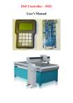
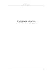
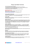
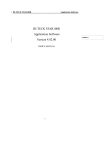
Switchboard
Installer manual
01GF-11W01
346310
2
Contents
1 Introduction
4
1.1 Warnings and recommendations
4
1.2 What’s in your box
4
2 Description 5
2.1 Main functions
5
2.2 Front view
6
2.3 Video door entry system function keys
7
2.4 Navigation keys
7
2.5 Back view
8
3 Installation 4 Settings 9
10
4.1 Handset (IU) D/N 12 Function
12
4.2 Slave handset (IU)
13
4.3 Modify contact
14
4.4 Time bands
17
4.5 Automations
18
4.6 Function Key Setup
19
4.7 Alarm Setup
20
4.8 Configuration
21
4.9 Change password 24
5 Advanced configuration
5.1 Connection to the PC
25
25
6 Troubleshooting
26
7 Appendix
27
3
Installer manual
Switchboard
1 Introduction
1.1 Warnings and recommendations
Before proceeding with the installation we recommend that you read the content of this manual very
carefully.
The warranty will automatically become void in case of negligence, improper use, tampering by
unauthorised personnel.
Therefore, the Switchboard:
- must only be installed indoors;
- must be kept away from water drips and sprays;
- must only be used in conjunction with BTicino 2 wire digital video door entry systems.
1.2 What’s in your box
In your box you will find:
• Switchboard
• CD with the manuals
4
2 Description
2.1 Main functions
Once correctly configured using the TiSwitchboardDevice program, in addition to performing the standard functions (door lock release and video monitoring), the switchboard can
also be used to receive and forward audio/video calls, and to manage alarms, both inside the
individual apartments of the 2 wire digital video door entry system, and in common areas.
The unit has a 7” LCD colour display, icon menu, menu navigation keys, and video door entry
system function keys.
The main functions of the switchboard are the following:
• call an apartment handset
• receive calls from Entrance Panels and forward them, if necessary, to the various apartment handsets
• receive standard or alarm calls from the apartments
• control the electrical door locks of the Entrance Panels
• switch the staircase lights on
• activate a relay
• switch on Entrance Panels or a cameras (monitoring)
• cycle through the cameras (surveillance)
The switchboard also provides the following:
• DAY/NIGHT management, with the possibility of only enabling the switchboard functions during
certain time bands (which can also be set by the user);
• a CALL LIST, saving all the unanswered calls received from apartment handsets;
• an HANDSET DIRECTORY and an ENTRANCE PANEL DIRECTORY. Their programming ensures easy
identification of the calling apartment or entrance panel.
INTEGRATIONS
Communication:
From the main menu screen, it is possible to access a range of video door entry system settings and
functions.
The keys also enable the activation of:
DIRECT CALL – intercommunicating call to an apartment handset
ACTIVATION – direct activation of the door lock associated to the entrance panel
DIRECTORY – display of the handset, entrance panel, and switchboard directories.
CAMERA/CYCLICAL SELECTION - direct activation of the camera associated to the entrance panel,
and cycling through the cameras present on the system
HANDSFREE – activation of handsfree mode.
Alarms:
It gives the possibility of receiving and managing alarms from apartment or common areas.
NOTE: The switchboard is unable to manage the calls from riser Entrance Panels “EP” (i.e.
entrance panels installed downstream interface 346851). Calls from riser Entrance Panels
“EP” will therefore always be forwarded directly to the Handsets “IU” (Internal Units).
5
Installer manual
Switchboard
2 Description
2.2 Front view
1 Handset
2 Colour LCD display; it displays the menus for the operation and programming functions. It
shows the images recorded from the entrance panel and from other cameras.
3 Handsfree microphone
4 Navigation key; it’s used to navigate through the menu and confirm the selections made
(OK key).
5 Cancel key
6 Direct call key
7 Door lock key
8 Directory key
9 Entrance panel activation and cycling key
10 Handsfree key
11 Active alarm LED
12 Switchboard status LED
13 Alphanumeric keypad
14 Configurable function keypad
15 Handsfree loudspeaker
6
2.3 Video door entry system function keys
Direct call key
To send the call to the desired apartment handset, after entering the associate
directory extension.
Door lock key
When the connection is activated, the door lock of the calling Entrance Panel
opens. When idle, the door lock of the associated Entrance Panel opens.
Directory key
It displays the handset, entrance panel, and switchboard directory screen.
Entrance Panel/ Cycle mode activation
It switches the associated Entrance Panel on and enables cycling through any
other Entrance Panels or cameras present.
Handsfree key
It activates the handsfree mode, excluding the handset, or vice versa.
2.4 Navigation keys
OK key
It switches the monitor on.
It provides access to the menu; it confirms the selection made.
Keys
They can be used to scroll horizontally or vertically through the menu items; In
some submenus, they can be used to change the values set.
C key
To Return to the previous screen; if the user is already on the first screen it can be
used to turn the display off.
7
Installer manual
Switchboard
2 Description
2.5 Back view
1 Mini-USB connector for connection to the PC
2 End of line ON/OFF micro switch
3 Connection to the BTicino 2 wire digital system BUS
4 Additional power supply connector (1-2)
5 Optional siren contact connector
8
3 Installation
1 Remove the cover from the base
2 Insert the cable in the appropriate slot
3 Connect to the bus (and to the additional power supply if required)
4 Replace the cover
9
Installer manual
Switchboard
4 Settings
After connecting and powering the switchboard, press OK to display the main menu.
Use the keys
to select the desired functions and press OK to confirm.
For a detailed description of all functions refer to the user manual that can be found in the CD
supplied.
Use the configuration icon to access to the installation setup menu. This menu is password protected and can only be accessed by the installer.
WARNING
1 5 actions
: 5 0 may
W e compromise
d n e s d a the
y operation of the switchboard.
Wrong
0 1 / 1 2 / 2 0 1 0
1
2 5 / 1 1 / 2 0 1 0
1 4 : 3 2
Select the Configuration functions
Press OK to confirm
2 3 / 1 1 / 2 0 1 0
1 3 : 4 7
C o n f i g u r a t i o n
1 5 : 5 0 W e d n e s d a y
0 1 / 1 2 / 2 0 1 0
1
2 5 / 1 1 / 2 0 1 0
1 4 : 3 2
Select the Installation Setup function
Press OK to display the access screen
2 3 / 1 1 / 2 0 1 0
1 3 : 4 7
I n s t a l l a t i o n
10
S e t u p
1 5 : 5 0 W e d n e s d a y
0 1 / 1 2 / 2 0 1 0
1 password using the keypad
Enter the
(default password: 12345)
P a s s w o r d :
2 5 / 1 1 / 2 0 1 0
* * * * *
1 4 : 3 2
Press OK to confirm
2 3 / 1 1 / 2 0 1 0
1 5 : 5 0 W e d n e s d a y
5
3
0 1 1/ 1 2 4
/ 2 0 12 0
6
1 3 : 4 7
The following icon screen appears:
1 Handset
(IU) D/N function
1
2 52/ 1Slave
1 / handset
2 0 1 0 (IU)
1 43: 3Modify
2
contact
4 Time bands
5 Automations
2 36/ 1Function
1 / 2 0 key
1 0setup
setup
1 37: 4Alarm
7
D / N
I U
7
F u n c t i o n
8
9
8 Configuration
9 Change password
11
Installer manual
Switchboard
4 Settings
4.1 Handset (IU) D/N function
1 5 : 5 0 W e d n e s d a y
This
can be used to enable or disable the handset “Day/Night” function.
0 1 / 1 2 / 2 0 1 0
1
2 5 / 1 1 / 2 0 1 0
1 4 : 3 2
Select the handset D/N function
Press OK to access the menu
2 3 / 1 1 / 2 0 1 0
1 3 : 4 7
D / N
I U
F u n c t i o n
1 5 : 5 0 W e d n e s d a y
0 1 / 1 2 / 2 0 1 0
D / N
I U
F u n c t i o n
E n a b l e d
1
2 5 / 1 1 / Press
2 0 1OK
0 repeatedly to enable/disable
1 4 : 3 2
the D/N function
Press to exit the menu
2 3 / 1 1 / 2 0 1 0
1 3 : 4 7
12
4.2 Slave handset (IU)
It can be used to enable or disable the slave handset (temporarily answer any calls received by the
1 5 : 5 0 W e d n e s d a y
switchboard),
and to configure the corresponding address.
0 1 / 1 2 / 2 0 1 0
1
2 5 / 1 1 / 2 0 1 0
1 4 : 3 2 Select the slave handset function
Press OK to access the menu
2 3 / 1 1 / 2 0 1 0
1 3 : 4 7
S e r v i c e
I U
1 5 : 5 0 W e d n e s d a y
0 1 / 1 2 / 2 0 1 0
To enable or disable the slave handset:
S l a v e
I U
Select the desired position
A d d r e s s
Press OK repeatedly to make
the selection
E n a b l e d
S l a v e
I U
A d d r e s s
0
To change the address:
Select the desired position
Press OK to highlight the
value to change
Change the value
Press OK to confirm
Press to exit the menu
13
Installer manual
Switchboard
4 Settings
4.3 Modify contact
1 5 : 5 0 W e d n e s d a y
It can
be used to create, change, or delete the contacts in the various directories.
0 1 / 1 2 / 2 0 1 0
1
2 5 / 1 1 / 2 0 1 0
1 4 : 3 2
Select the Modify Contact function
Press OK to access the menu
2 3 / 1 1 / 2 0 1 0
1 3 : 4 7
M o d i f y C o n t a c t
1 5 : 5 0 W e d n e s d a y
0 1 / 1 2 / 2 0 1 0
C h a n g e
I U
C o n t a c t
A d d r e s s
B o o k
Press OK repeatedly to select the desired
directory
1 5 : 5 0 W e d n e s d a y
0 1 / 1 2 / 2 0 1 0
C h a n g e
I U
C o n t a c t
A d d r e s s
B o o k
Select the desired action:
Create – Modify - Delete
Press OK to confirm
C r e a t e
14
1 5 : 5 0
- Create
0 1 / 1 2
W e d n e s d a y
/ 2 0 1 0
I n t e r n a l
> S C S
A d d r .
L o g i c
Move the cursor to the existing parameters in succession
U n i t
0
A d d r e s s
0
Use the keypad to enter the new value,
or description
D e s c r i p t i o n
B l o c k
0
F l o o r
0
A p a r t m e n t
0
S a v e
1 5 : 5 0
- Modify
0 1 / 1 2
Press OK to highlight data for which the
value must be entered
Press OK to confirm
Once the necessary details have been
entered move the cursor to Save
Press OK to save the new contact
Press to exit the menu
W e d n e s d a y
/ 2 0 1 0
M o d i f y
-
0
A p a r t m e n t
2
2
A p a r t m e n t
3
3
A p a r t m e n t
4
4
A p a r t m e n t
5
5
A p a r t m e n t
6
6
A
1 5p :a 5r 0t mWe en dt n 7e s d a y
0 1 / 1 2 / 2 0 1 0
I n t e r n a l
> S C S
L o g i c
A d d r e s s
A quick search bar is also present, where
the user can enter the details of the
required contact using the keypad
7
Select the parameter that needs changing
and press OK
U n i t
A d d r .
Select the contact to modify and press
OK
0
0
D e s c r i p t i o n
Use the keypad to enter the new value,
or description
Cancel the entry in case of mistake
B l o c k
0
F l o o r
0
A p a r t m e n t
0
Press OK to confirm
Move the cursor to Save
S a v e
Press OK to save the changes made
15
Installer manual
Switchboard
4 Settings
WARNING:
The switchboard makes direct calls using the logic addresses.
1 5 : 5 0
- Delete
0 1 / 1 2
W e d n e s d a y
/ 2 0 1 0
D e l e t e
Move the cursor to the contact to delete
-
0
A p a r t m e n t
2
2
A p a r t m e n t
3
3
A p a r t m e n t
4
4
A p a r t m e n t
5
5
A p a r t m e n t
6
6
A p a r t m e n t
7
7
16
Press OK to delete the contact
Press to exit the menu
4.4 Time bands
For each day of the week, it is possible to set up to 3 day start and night start time bands, upon
which the switchboard will automatically switch from one status to the other.
NOTE: This mode is active when the “Day/Night” function of the configuration menu is set to auto1 5 : 5 0 W e d n e s d a y
matic
(see User Manual).
0 1 / 1 2 / 2 0 1 0
1
2 5 / 1 1 / 2 0 1 0
1 4 : 3 2
Select the Time Bands function
Press OK to display the screen used to
enter the time bands
2 3 / 1 1 / 2 0 1 0
1 3 : 4 7
T i m e
B a n d s
1 5 : 5 0 W e d n e s d a y
0 1 / 1 2 / 2 0 1 0
T i m e
Press OK repeatedly to select
the day of the week
B a n d s
M o n d a y
F - 1
D a y
S t a r t
F - 2
N i g h t
F - 3
D a y
F - 4
N i g h t
F - 5
D a y
F - 6
N i g h t
S t a r t
S t a r t
S t a r t
S t a r t
S t a r t
- - : - - - : - - - : - - - : - - - : - - - : - -
Select “Weekday” to set the time bands
for every day from Monday to Friday at
the same time.
Select the desired time band
Press OK to highlight the
value to change
Use the keypad to enter the desired
time; use the key to delete wrong
entries;
Press OK twice to delete the selected
time band and all subsequent ones.
Press OK to confirm and continue with the subsequent
time bands
Press to exit the menu
17
Installer manual
Switchboard
4 Settings
4.5 Automations
This function can be used to configure up to 5 entrance panels, so that the corresponding door
1 5can
: 5be0 released
W e d when
n e sno
d calls
a y are active from the entrance panel.
locks
0 1 / 1 2 / 2 0 1 0
1
2 5 / 1 1 / 2 0 1 0
1 4 : 3 2
Select the Automation function
Press OK to access the menu
2 3 / 1 1 / 2 0 1 0
1 3 : 4 7
A u t o m a t i o n
1 5 : 5 0 W e d n e s d a y
0 1 / 1 2 / 2 0 1 0
L o c k
S C S A d d r.
C o n f i g u r a t i o n
Description
E P
Select the parameter to set
Riser
1
M a i n
0
2
-
1
3
-
1
4
-
1
5
-
1
Press OK to highlight the
entry field
Use the keypad to enter the desired
value or description
Press OK to confirm
Press to exit the menu
18
4.6 Function key setup
It is possible to configure each of the 12 keys of the dedicated keypad to perform a certain
1 5 : 5 0 W e d n e s d a y
function.
0 1 / 1 2 / 2 0 1 0
1
2 5 / 1 1 / 2 0 1 0
1 4 : 3 2
Select Function Keys Setup
Press OK to access the menu
2 3 / 1 1 / 2 0 1 0
1 3 : 4 7
F u n c t i o n
K e y
S e t u p
1 5 : 5 0 W e d n e s d a y
0 1 / 1 2 / 2 0 1 0
F u n c t i o n
K e y
K e y
S e t u p
F
Press OK repeatedly to select the key to configure
(F1 to F12)
S e t u p
1
Select Function
F u n c t i o n
D o o r
l o c k
1
d o o r 1
S C S
A d d r .
R i s e r
6
6
Press OK repeatedly to select
the function to associate with
the key.
Press to exit the menu
List of configurable functions:
Door lock 1 to 5
Handset Day/Night
Entrance panel Day/Night
Presence status
Slave handset
Staircase light
Handset Call
Entrance panel Call
Switchboard call
_______ _ _ _ _ _ _ _(not configured)
19
Installer manual
Switchboard
4 Settings
4.7 Alarm setup
It can be used to enable or disable:
- alarms (burglar alarms, panic alarms, technical alarms)
1 5contact
: 5 0 forWthe
e external
d n e ssiren
d a (or
y luminous signalling ), accessible from the back of the switchboard
- the
0 1 / 1 2 / 2 0 1 0
1
2 5 / 1 1 / 2 0 1 0
1 4 : 3 2 Select the Alarm Setup function
Press OK to access the menu
2 3 / 1 1 / 2 0 1 0
1 3 : 4 7
A l a r m s
S e t u p
1 5 : 5 0 W e d n e s d a y
0 1 / 1 2 / 2 0 1 0
A l a r m s
Select the desired item
E n a b l e d
S i r e n
Press OK repeatedly to enable/disable
the function
E n a b l e d
Press to exit the menu
NOTE: The alarm function can also be enabled
during the day only.
WARNING:
Alarms can only be managed from the main switchboard (local address 0).
20
4.8 Configuration
This function enables the initial configuration through:
- local switchboard address setup:
- associated entrance panel address setup;
- associated camera enabling/disabling;
- directory type selection (type 1: alphanumeric; type 2: coding (BPI);
1 5 : 5 0 W e d n e s d a y
- selection
of the navigation language.
0 1 / 1 2 / 2 0 1 0
1
2 5 / 1 1 / 2 0 1 0
1 4 : 3 2 Select the Configuration functions
Press to access the menu
2 3 / 1 1 / 2 0 1 0
1 3 : 4 7
C o n f i g u r a t i o n
1 5 : 5 0 W e d n e s d a y
0 1 / 1 2 / 2 0 1 0
L o c a l
A d d r e s s
A s s o c i a t e d
E P
L i s t
A s s o c i a t e d
A c t i v a t e d
C a m e r a
Alphanumeric Address Book
To change the local address of the
main “EP”:
Select Local address
Press OK to confirm
E n g l i s h
21
Installer manual
Switchboard
4 Settings
1 5 : 5 0 W e d n e s d a y
0 1 / 1 2 / 2 0 1 0
> L o c a l
A d d r e s s
0
M a i n
Associated Switchb.
M a i n
--
E P
1
Select the desired item
Press OK to highlight the
value to change
Use the keypad to change the value
Press OK to confirm
NOTE: If only one switchboard is
present, this must be configured
as primary switchboard, with local
address 0.
When more than one switchboard are
present, any switchboard can be set
as primary (only one for each system),
or secondary (local address 1 to 15).
In this case, enter the address of the
associated primary switchboard in
the appropriate field.
1 5 : 5 0 W e d n e s d a y
0 1 / 1 2 / 2 0 1 0
L o c a l
A d d r e s s
A s s o c i a t e d
E P
L i s t
A s s o c i a t e d
A c t i v a t e d
C a m e r a
For the list of the associated Entrance
Panels on which the transfer from Day
to Night mode should be managed:
Select Associated EP List
Alphanumeric Address Book
Press OK to confirm
E n g l i s h
22
1 5 : 5 0 W e d n e s d a y
0 1 / 1 2 / 2 0 1 0
A s s o c i a t e d
E P
Press OK to confirm
L i s t
1 :
I n d . S c s
Press OK repeatedly to move
the cursor to the desired EP
- -
Move the cursor to the SCS
address line
Press OK to highlight the
value to change
Use the keypad to enter the value
Press OK to confirm
Press to exit the menu
1 5 : 5 0 W e d n e s d a y
0 1 / 1 2 / 2 0 1 0
L o c a l
A d d r e s s
A s s o c i a t e d
E P
L i s t
A s s o c i a t e d
A c t i v a t e d
C a m e r a
Alphanumeric Address Book
E n g l i s h
To activate the associated camera; to
select the directory or the language:
Select the desired item
Press OK repeatedly to make
the selection
Press to exit the menu
Directory type:
- Alphanumeric: for each contact the content of the “Description” field will be displayed
- Block-Floor-Apartment: for each contact the content of the fields Block-Floor-Apartment will be
displayed.
For more information see the “Modify Contact” section.
23
Installer manual
Switchboard
4 Settings
4.9 Change password
This function is used to change the password for access to the Installation setup section. The de1 5password
: 5 0 W
e d n e s d a y
fault
is 12345.
0 1 / 1 2 / 2 0 1 0
1
2 5 / 1 1 / 2 0 1 0
1 4 : 3 2 Select the Change Password function
Press OK to confirm
2 3 / 1 1 / 2 0 1 0
1 3 : 4 7
C h a n g e
P a s s w o r d
1 5 : 5 0 W e d n e s d a y
0 1 / 1 2 / 2 0 1 0
1
N e w
P a s s w o r d
Enter the new password using the keypad (max.
2 55 /digit
1 1 number)
/ 2 0 1 0 Press
repeatedly to delete
1 4entries
: 3 2 made
1
Press OK to confirm and exit the menu.
2 3 / 1 1 / 2 0 1 0
1 3 : 4 7
1 5 : 5 0 W e d n e s d a y
0 1 / 1 2 / 2 0 1 0
1
N e w P a s s w o r d
S t o r e d !
2 5 / 1 1 / 2 0 1 0
1 4 : 3 2
2 3 / 1 1 / 2 0 1 0
1 3 : 4 7
24
5 Advanced configuration
As an alternative to the menu setup, it is also possible to configure the switchboard from the PC,
using the TiSwitchBoardDevice software found in the CD supplied.
WARNING
Some functions, like the creation of the directories and the management of the bells, can only be
performed using the software.
5.1 Connection to the PC
To transfer the configuration performed using the TiSwitchBoardDevice software, or to update the
Firmware, connect the switchboard to the PC using an USB/miniUSB cable.
To enable communication the switchboard must be powered.
25
Installer manual
Switchboard
6 Troubleshooting
Problem
Solution
No image appears when the Entrance Panel/
Cycling key
is pressed
- check that the switchboard is correctly wired
and configured;
- the audio/video channel may be busy, wait
for it to become free and try again
No control is performed when the Door
Lock key is pressed
- check that the switchboard is correctly wired
and configured;
The switchboard does not ring
- check that the switchboard is correctly wired
and configured;
- check that the bell volume has not been
turned right down.
- speak at a maximum distance of 50 cm from
the handsfree microphone;
From the entrance panel it is difficult to hear
- reduce the volume of the entrance panel
who is speaking
microphone and increase the volume of the
EP speaker
26
7 Appendix
TECHNICAL DATA
from SCS BUS: 19 - 27 V
Power supply
from 12: 18 - 27 V
Absorption (Max) from
BUS with additional
power supply
20 mA (A/V connection - at the minimum operating voltage)
Absorption (Max) from
BUS without additional
power supply
450 mA (A/V connection - at the minimum operating voltage)
Operating temperature
0 – 40 °C
Absorption (Max)
from 1-2
300 mA
5 mA (in stand-by)
35 mA (in stand-by)
Note about the LCD screen
The LCD screen has been produced using state of the art high precision technology. It
may however happen that up to 5 small black and/or red, blue, or green dots will appear
on the LCD screen. This is normal and does not indicate wrong and/or faulty operations.
290 mm
210 mm
170 mm
170 mm
27
Installer manual
Switchboard
BTicino SpA
Via Messina, 38
20154 Milano - Italy
www.bticino.com
BTicino SpA reserves at any time the right to modify the contents of this booklet and to communicate,
in any form and modality, the changes brought to the same.