1
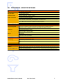
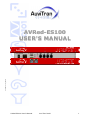
Version 1.0 July 2008
AVRed-ES100
USER’S MANUAL
AVRed-ES100 User’s Manual
AuviTran 2008
1
TABLE OF CONTENTS
1-
WELCOME!........................................................................................................ 3
2-
ELECTRICAL AND ELECTRONIC INTERFERENCES RISKS......................... 3
3-
LIMITATION OF LIABILITY ............................................................................... 3
4-
FCC .................................................................................................................... 4
5-
TRADEMARKS .................................................................................................. 5
6-
COPYRIGHT ...................................................................................................... 5
7-
AUVITRAN WEBSITE / MORE INFORMATION................................................ 5
8-
PACKAGE CONTAINS ...................................................................................... 5
9-
PRECAUTIONS ................................................................................................. 6
10- TECHNICAL SPECIFICATIONS........................................................................ 7
11- REAR PANEL DESCRIPTION........................................................................... 8
12- ARCHITECTURE USING AVRED-ES100.......................................................... 9
13- AVRED-ES100 MODES ................................................................................... 10
13-1 Dip switches Mode setting................................................................... 10
13-2 Copper / Optical setting ...................................................................... 10
13-3 Connection schematics........................................................................ 11
13-3-1 AVRed / AVRed mode ................................................................... 11
13-3-2 Switch / AVRed mode ................................................................... 11
13-4 Why using AVRed-ES100 in Pair instead of with a switch ................... 12
14- THIRD PORT AND REMOTE CONTROL ........................................................ 12
14-1 Example of architecture using 3rd port ................................................ 12
14-2 Limitations of architectures ................................................................ 13
15- AVRED-ES100 IN ESMONITOR SOFTWARE ................................................ 14
15-1 Software Installation .......................................................................... 14
15-2 Getting Started with AVRed-ES100 and ESMonitor Software............... 14
15-3 AVRed-ES100 Properties Page in ESMonitor........................................ 14
15-4 AVRed-ES100 Control Page in ESMonitor ............................................ 15
15-4-1 AVRed-ES100 Mode...................................................................... 16
15-4-2 Links Status box .......................................................................... 16
15-4-3 Links Options............................................................................... 17
15-4-4 Status box .................................................................................. 17
15-4-5 Bi-directional Status box ............................................................... 18
15-4-6 Mode box.................................................................................... 18
15-4-7 Clock Setting box ......................................................................... 18
15-4-8 Serial Communication Mode box..................................................... 18
15-4-9 Serial Port Configuration box ......................................................... 18
16- AUXILIARY POWER SUPPLY ........................................................................ 19
AVRed-ES100 User’s Manual
AuviTran 2008
2
1- WELCOME!
Thank you for purchasing AuviTran’s AVRed-ES100. We hope you will enjoy using it. This
product will helps you building secure redundant EtherSound networks. AVRed-ES100
guarantees that your digital EtherSound connection is secured by a second path. In case
of cable failure or even only data errors, the AVRed-ES100 boxes will automatically
switch on the best cable.
AVRed-ES100 is currently the fastest ever built redundancy system that will switch on
the best cable in less than 100µs and 3.2µs pass-thru latency.
The AVRed-ES100 boxes offer full network and/or local control of all parameters as well
as constant network status monitoring, making it ideal for live professional audio
applications. Build-in serial port allows you to build serial tunneling communications
thanks to native ES100 kernel. Also, word clock input and output are available for
external audio synchronization over the network. Auxiliary power supply connector
ensures extra redundancy of your system.
You will find herewith the necessary instructions to use your product. Please read them
carefully as misuse of this device might cause serious damage to you and your
environment.
2- ELECTRICAL AND ELECTRONIC INTERFERENCES RISKS
This Product uses high frequency digital circuits that might interfere with electrical or
electronic devices placed in your working environment. Please make sure this kind of
device (television, radio device, cell phones) is removed in order to ensure a proper
functioning of each device.
Always use shielded cables and connectors (serial port, word clock and EtherSound
ports). In the other case, AuviTran will not guarantee the proper behavior of the
product.
Serial port cable must be length < 1m to ensure proper EMC and interferences
behavior.
Word clock cable must be length < 1m to ensure proper EMC and interferences
behavior.
3- LIMITATION OF LIABILITY
In no case and in no way, the provider of this Product (AuviTran, the distributor or
reseller, or any other party acting as provider) shall be liable and sued to court for
damage, either direct or indirect, caused by and to the user of the board and which
would result from an improper installation or misuse of the Product. “Misuse” and
“improper installation” mean installation and use not corresponding to the instructions of
this manual.
Please note that graphics given in this manual (drawings and schemes) are only
examples and shall not be taken for a real vision of your own equipment configuration.
AuviTran is constantly working on the improvement of the products. For that purpose,
the products functionalities are bound to change and be upgraded without notice. Please
read carefully the User’s manual as the new functionalities will be described therein.
AVRed-ES100 User’s Manual
AuviTran 2008
3
4- FCC
This device complies with Part 15 of the FCC rules. Operation is subject to the following
two conditions:
1. This device may not cause harmful interference.
2. This device must accept any interference received including interference that may
cause undesired operation.
FCC INFORMATION (U.S.A.)
1. IMPORTANT NOTICE: DO NOT MODIFY THIS UNIT!
This product, when installed as indicated in the instructions contained in this manual, meets FCC
requirements. Modifications not expressly approved by Yamaha may void your authority, granted by the
FCC, to use the product.
2. IMPORTANT: When connecting this product to accessories and/or another product use only high
quality shielded cables. Cable/s supplied with this product MUST be used. Follow all installation instructions.
Failure to follow instructions could void your FCC authorization to use this product in the USA.
3. NOTE: This product has been tested and found to comply with the limits for a Class B Digital device,
pursuant to Part 15 of the FCC Rules. These limits are designed to provide reasonable protection against
harmful interference in a residential environment. This equipment generates, uses and can radiate radio
frequency energy and, if not installed and used according to the instructions found in the users manual, may
cause interference harmful to the operation of other radio communications.
Compliance with FCC
regulations does not guarantee that interference will not occur in all installations. If this product is found to
be the source of interference, which can be determined by turning the unit “OFF” and “ON”, please try to
eliminate the problems by using one of the following measures:
Relocate either this product or the device that is being affected by the interference.
Utilize power outlets that are on different branch (circuit breaker or fuse) circuits or install AC line
filter(s).
In the case of radio or TV interference, relocate/reorient the antenna. If the antenna lead-in is 300
ohm ribbon lead, change the lead-in to co-axial type cable.
If these corrective measures do not produce satisfactory results, please contact the local retailer authorized
to distribute this type of product. If you cannot locate the appropriate retailer, please contact Yamaha
Commercial Audio Systems, Inc., Electronic Service Division, 6600 Orangethorpe Ave, Buena Park,
CA90620.
The above statements apply ONLY to those products distributed by Yamaha Commercial Audio Systems, Inc.
or its subsidiaries.
COMPLIANCE INFORMATION STATEMENT
(DECLARATION OF CONFORMITY PROCEDURE)
Responsible Party :
Address :
Telephone :
Type of Equipment :
Model Name :
Yamaha Commercial Audio Systems, Inc.
6600 Orangethorpe Ave.,
Buena Park, Calif. 90620
714-522-9011
EtherSound Redundant links
AVRed-ES100
This device complies with Part 15 of the FCC Rules.
Operation is subject to the following conditions:
1) This device may not cause harmful interference, and
2) This device must accept any interference received including
interference that may cause undesired operation.
See user manual instructions if interference to radio reception is
suspected.
AVRed-ES100 User’s Manual
AuviTran 2008
4
5- TRADEMARKS
All trademarks listed in this manual are the exclusive property of their respective owners.
They are respected “as is” by AuviTran. Any use of these trademarks must receive prior
approval of their respective owners. For any question, please contact the trademark’s
owner directly.
6- COPYRIGHT
The information in this manual is protected by copyright. Therefore, reproduction,
distribution of whole or part of this manual is strictly forbidden without the prior written
agreement of AuviTran.
7- AUVITRAN WEBSITE / MORE INFORMATION
Please visit our website for any question of further inquiry concerning our product range.
Updates will also be posted when available.
http://www.auvitran.com
8- PACKAGE CONTAINS
•
1 AVRed-ES100
L Cord-set with proper plug configuration must be used, depending on country in
which the product is used
AVRed-ES100 User’s Manual
AuviTran 2008
5
9- PRECAUTIONS
Do not modify, open or disassemble the Product. The guarantee shall be null and
void in that case.
Do not apply excessive pressure on connectors or any other part of the board. Do
not touch the metallic sharp parts (pins) of the product.
This product is designed to be rack-mounted. Be sure to observe following
installation rules of this kind of equipment:
• Elevated Operating Ambient - If installed in a closed or multi-unit rack assembly,
the operating ambient temperature of the rack environment may be greater than
room ambient. Therefore, consideration should be given to installing the
equipment in an environment compatible with the maximum ambient temperature
(Tma) specified by the manufacturer.
• Reduced Air Flow - Installation of the equipment in a rack should be such that the
amount of air flow required for safe operation of the equipment is not
compromised.
• Mechanical Loading - Mounting of the equipment in the rack should be such that a
hazardous condition is not achieved due to uneven mechanical loading.
• Circuit Overloading - Consideration should be given to the connection of the
equipment to the supply circuit and the effect that overloading of the circuits
might have on over current protection and supply wiring. Appropriate
consideration of equipment nameplate ratings should be used when addressing
this concern.
• Reliable Earthing - Reliable earthing of rack-mounted equipment should be
maintained. Particular attention should be given to supply connections other than
direct connections to the branch circuit (e.g. use of power strips).
This product is electrostatic sensitive; make sure you check this before touching or
using it.
The disconnect devices of the unit are the appliance inlet of the auxiliary power
supply and the appliance inlet on the rear side of the unit. These must be easily
reachable.
Conformity of this product is subject to proper electrical wiring, regarding CEI364
(NFC15-100). Installation must be equipped with differential protection.
To prevent electric shock, do not remove the cover. No user-serviceable parts
inside. This unit contains hazardous voltages and should only be opened by a
trained and qualified technician. Both power supply sources must be disconnected
before servicing.
Each connection must be Safety Extra Low Voltage kind (SELV), and must stay
inside buildings.
FI: "Laite on liitettävä suojamaadoituskoskettimilla varustettuun pistorasiaan"
NO: "Apparatet må tilkoples jordet stikkontakt"
SE: "Apparaten skall anslutas till jordat uttag"
AVRed-ES100 User’s Manual
AuviTran 2008
6
10- TECHNICAL SPECIFICATIONS
General
Size
Power Consumption
Main Power Supply
DC supply (Auxiliary)
Auxiliary Power Supply
Storage: Temp/Humidity
Operating: Temp/Humidity
Front Panel
Rear Panel
Optical Fiber
483 x 253 x 44mm (19’ rack / 1U Height)
<50 Watts
100-240VAC 50/60Hz 1.5A Max
5Vdc 5A max – 12Vdc 2A max
100-240V~ 47-63Hz 1.35A / +5Vdc 5A ; +12Vdc 2A
- 5°C to 70°C / Max 95% (non-condensing)
5°C to 40°C / 5% to 90% (non-condensing)
Network and links Rx and Tx Activities; Active link running ; Quality Status of both Links A and B ; In or Out Mode selected for
device ; Power Main, Aux and On Display; 2 Neutrik OpticalCon™ for /FoNeutrik version
1 IEC Power inlet; 4 Neutrik EtherCon RJ45; 1x6 poles Euroblock Connector for Aux power supply; 2 BNC for word clock synch in
and out; 1 DB9 connector for Serial Port; 4 Dip Switches for hardware configuration
62.5/125 Multimode fiber used with LC connectors or Neutrik Opticalcon™
AVRed-ES100 Features
3 Operating modes
set by external dip switch
EtherSound I/O
Resilient Link
Pass-through Latency
Link Switching latency
Other I/O
Clock
Mode IN: EtherSound Input to 2 resilient links
Mode OUT on AVRed-ES: 2 resilient links coming from an AVRed-ES module to one EtherSound Output Port
Mode OUT on Switch: 2 resilient links coming from an Ethernet Switch to one EtherSound Output Port
IN or OUT port depending of operating mode selected; 3rd port for PC remote control
A and B with automatic selection of best link
2.8µs in AVRed-ES100 – AVRed-ES100 Mode
Approx 22µs in Switch – AVRed-ES100 Mode
4 samples (83µs at 48 kHz)
RS232 serial port
48 kHz local clock (when Primary Master) or EtherSound Network (When not PM)
Word clock In used for synchronization
Temp / Fan monitoring
Temp Monitoring
PSU Monitoring
2 Fan Control modes
Network Monitoring of Temperature inside the Box
Network Monitoring of PSU Failure for Main and Aux power supply
Automatically Controlled by internal Temperature
Off
Development and Integration Environment
OS Supported
ES-Monitor
Remote Network Management
Windows XP
ES-Monitor enables to remotely set, control and monitor an EtherSound network and provides enhanced property pages to manage
the AVRed-ES100 specific parameters.
Links status, Power supply status (Main, Aux), Temperature monitoring , Fan remote control and PSU Aux/Main remote control
AVRed-ES100 User’s Manual
AuviTran 2008
7
11- Rear Panel Description
1- Power switch : switch on or off the main power supply
2- AC IN : main power supply. Refer to tech specs for AC range
3- DC IN : auxiliary power supply for redundancy purpose
4- Dip switches : setup the device
5- Serial Port : standard RS232 for custom application
6- Word Clock : Input and Output for external synchronization
7- EtherSound Ports : link to EtherSound network (or control PC)
8- Redundant Links : double Cat.5 redundant links
Here is the detailed description of the dip switches. Every setup will be explained below.
AVRed-ES100 User’s Manual
AuviTran 2008
8
12- Architecture using AVRed-ES100
A pair of AVRed-ES100 boxes will build a redundant link composed of 2 Cat.5 cables (or
fibres for AVRed-ES100/FoNeutrik). If one link breaks down, AVRed-ES100 will quickly
switch on the second one. Status of both links is displayed on ESMonitor software and on
front panel.
AVRed-ES100 User’s Manual
AuviTran 2008
9
13- AVRed-ES100 Modes
AVRed-ES100 is able to work in 3 different modes that are set up with dip switches on
the rear panel of the box.
13-1 Dip switches Mode setting
13-2 Copper / Optical setting
If you own an AVRed-ES100/FoNeutrik, you can choose if you want to use optical fiber
connectors, or switch back to regular copper RJ45 connectors. This setting is useless if
you own a standard AVRed-ES100.
AVRed-ES100 User’s Manual
AuviTran 2008
10
13-3 Connection schematics
13-3-1
AVRed / AVRed mode
13-3-2
Switch / AVRed mode
AVRed-ES100 User’s Manual
AuviTran 2008
11
13-4 Why using AVRed-ES100 in Pair instead of with a switch
When using a combo of 2 AVRed-ES100 Boxes instead of switch + AVRed-ES100,
computation of link status is more precise and allows more accurate switch between
links. The Switch / AVRed-ES100 Mode combo will only detect cable disconnection, while
AVRed-ES100 / AVRed-ES100 Mode will detect cable failure including quality status.
The AVRed-ES100 / AVRed-ES100 mode allows system to precisely analyse status of
each pair of cables. Therefore, system can choose the best pair for both upstream and
downstream signals. Consequently, if errors occur on both links, the system is able to
use one cable for upstream and the other for downstream provided this gives better
results. This feature is not available on Switch / AVRed-ES100 Mode.
Last but not the least, the AVRed-ES100 / AVRed-ES100 Mode proves better results (by
ten times superior) in terms of latency for the redundant link than the Switch / AVRedES100 Mode.
14- Third Port and Remote Control
AVRed-ES100 was built with the latest EtherSound ES100 technology, and includes a 3rd
port for remote control and monitoring. With previous version of EtherSound, the control
PC should always be connected to the “IN port” of the first EtherSound device in the
network, i.e. the primary master.
Now, thanks to EtherSound ES100, and native AVRed-ES100 3rd port, you can plug your
control PC directly to your device, even if it is not primary master.
14-1 Example of architecture using 3rd port
AVRed-ES100 User’s Manual
AuviTran 2008
12
14-2 Limitations of architectures
Remote control via 3rd port of your ES100 device is subject to few limitations
when in heterogeneous EtherSound network (i.e. ES100 and non-ES100
devices). Please read carefully following points:
-
The primary master of the network should always be an ES100 EtherSound device.
If a non-ES100 device is within the daisy-chain, 3rd port enables remote PC control of
the local device only (if not primary master).
AVRed-ES100 User’s Manual
AuviTran 2008
13
15- AVRed-ES100 IN ESMONITOR SOFTWARE
15-1 Software Installation
Please visit our website to download the latest version of our EtherSound Monitor
Software
called
ESMonitor
(http://www.auvitran.com/view.php?products_AVSESMonitor.php ) and save the file on your hard disk. ESMonitor requires Windows XP to
function.
You are now ready for installation. Refer to the ESMonitor documentation for installation.
When ESMonitor is installed on your PC, you can run ESMonitor and manage any
AVMRed-ES100 devices connected to an EtherSound network. Refer to ESMonitor
documentation for generic EtherSound device management such as Enumeration of
EtherSound devices.
15-2 Getting Started with AVRed-ES100 and ESMonitor Software
The computer on which the EtherSound Monitor is installed should now be connected to
the primary master of the EtherSound network. The primary master must be the first
EtherSound-based device of the network.
After running the ESMonitor, Select an AVRed-ES100 device on the device list or tree list.
15-3 AVRed-ES100 Properties Page in ESMonitor
When selecting the properties page, ESMonitor will display the following information:
AVRed-ES100 User’s Manual
AuviTran 2008
14
15-4 AVRed-ES100 Control Page in ESMonitor
If the Control page is selected, ESMonitor will display following information:
All standard parameters of the AVRed-ES100 can be seen or changed in this control
page.
You can now start the configuration of your network and enjoy the functionalities of
AuviTran AVRed-ES100.
AVRed-ES100 User’s Manual
AuviTran 2008
15
15-4-1
AVRed-ES100 Mode
The scheme below shows the current mode of your the AVRed-ES100:
1- Mode Output from Switch:
2- Mode Output from AVRed-ES100:
3- Mode Input:
15-4-2
Links Status box
The link status is shown with colours:
Green for a good link.
Orange for a link with errors.
Red for a broken link.
AVRed-ES100 User’s Manual
AuviTran 2008
16
The active link is in Bold.
The front panel (on box and in ESMonitor) shows the active link (1) and the error
memory (2). As errors are sometimes too fast to be seen on Leds or because you were
away when the error occurred, Error memory is blinking during 20s.
15-4-3
Links Options
Swap Link
Swap link button
allows user to swap active link if possible.
Priority Link
When available on device, priority link management allows device to automatically select
first link. To activate priority link management, button
must be selected.
Note: Option must be set on both side of redundant link (i.e. selected on both AVRedES100 control page).
15-4-4
Status box
The Status box shows temperature in the box, fan speed and its turn-off switch, and the
front panel brightness setting.
Fan speed is automatic, depending on box temperature. Thresholds were optimized
regarding fan noise and maximum working temperature. For noise-critical environment,
fan can be turn-off.
L Please note that if internal temperature becomes too high, AVRed-ES100 will override
the “Stop Fan” command to ensure proper cooling of the box.
AVRed-ES100 User’s Manual
AuviTran 2008
17
15-4-5
Bi-directional Status box
If AVRed-ES100 is inside a bi-directional ES network, this box will display the “BiDirectional mode ON” message. You can also force the device to be end of bi-directional
loop, thanks to “Loopback” checkbox.
15-4-6
Mode box
If you own an AVRed-ES100/FoNeutrik, this box shows you if redundant links are routed
on the back panel EtherCon® RJ45 connectors or on the front panel OpticalCon® optical
connectors. It is a read-only display, as you must use back panel Dip Switches to change
mode.
15-4-7
Clock Setting box
This control box enables you to choose the clock source of your network, in case your
AVRed-ES100 is the Primary Master.
15-4-8
Serial Communication Mode box
This box helps you to create a Unicast serial tunneling between AVRed-ES100 serial port,
and a remote device. All you have to do is to check the “Unicast” button and choose the
destination device of the communication to create the tunnel.
If you leave the “Slave” button checked, that means that AVRed-ES100 is able to
communicate with a remote device that was configured to communicate with.
15-4-9
Serial Port Configuration box
This box will helps you to configure properly the physical serial port parameters, as baud
rate, parity, etc.
AVRed-ES100 User’s Manual
AuviTran 2008
18
16- Auxiliary power supply
AVRed-ES100 provides another source of power supply, to improve the reliability of the
system. It allows you to have two distinct power supply sources, for redundancy
solutions. When both power supply units (PSU) are plugged, AVRed-ES100 monitors
them, and always chooses best. In case of failure of one PSU (or associated electrical
network), AVRed-ES100 will so continue to work.
Auxiliary PSU (ref. AVPSAUX-E45/EB) is validated and provided by AuviTran only. Please
contact us if you want to integrate the redundant PSU in your system.
http://www.auvitran.com
AVRed-ES100 User’s Manual
AuviTran 2008
19