1
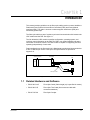
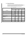
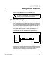
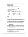
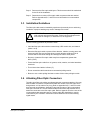
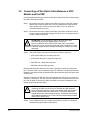
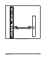
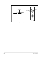
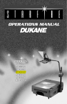
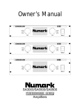
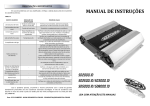
Distributed Power System
Fiber-Optic Cabling
Instruction Manual S-3009-3
Throughout this manual, the following notes are used to alert you to safety considerations:
!
ATTENTION: Identifies information about practices or circumstances that can lead to personal
injury or death, property damage, or economic loss.
Important: Identifies information that is critical for successful application and understanding of the product.
The thick black bar shown at the margin of this paragraph will be used throughout this manual to indicate new
or revised text or figures.
!
ATTENTION: Only qualified personnel familiar with the construction and operation of this
equipment and the hazards involved should install, adjust, operate, or service this equipment.
Read and understand this manual and other applicable manuals in their entirety before
proceeding. Failure to observe this precaution could result in severe bodily injury or loss of life.
ATTENTION: The user is responsible for conforming with all applicable local, national, and
international codes. Failure to observe this precaution could result in damage to, or destruction
of, the equipment.
The information in this user’s manual is subject to change without notice.
Belden® is a registered trademark of Belden, Inc.
ST® is a registered trademark of AT&T.
AutoMax™ and PowerMax™ are trademarks of Rockwell Automation.
© 1998 Rockwell International Corporation
CONTENTS
Chapter 1
Introduction
1.1 Related Hardware and Software ..................................................................... 1-1
1.2 Related Publications ........................................................................................ 1-2
1.2.1 1567 Power Max™ Documentation....................................................... 1-3
Chapter 2
Fiber-Optic Cable Assembly Components
2.1 Cable ............................................................................................................... 2-1
2.2 Connectors ...................................................................................................... 2-1
Chapter 3
Fiber-Optic Link Installation
3.1 Optical Power Budget ...................................................................................... 3-1
3.2 Installation Planning ........................................................................................ 3-2
3.3 Installation Guidelines ..................................................................................... 3-3
3.4 Attaching Fiber-Optic Connectors ................................................................... 3-3
3.5 Connecting a Fiber-Optic Cable Between a UDC Module and the PMI .......... 3-4
Chapter 4
Fiber-Optic Link Testing and Troubleshooting
4.1 COMM OK LEDs ............................................................................................. 4-1
4.2 DRV FLT LEDs ................................................................................................ 4-2
Appendix A Fiber-Optic Link Specifications .................................................................................A-1
Appendix B 62.5 Micron Fiber-Optic Cable Specifications...........................................................B-1
Appendix C 50 Micron Fiber-Optic Cable Specifications..............................................................C-1
Appendix D Fiber-Optic Connector Specifications .......................................................................D-1
Appendix E Fiber-Optic Cable Assembly Test Set Specifications ...............................................E-1
Table of Contents
I
II
Fiber-Optic Cabling
List of Figures
Figure 1.1 – Fiber-Optic Serial Communication Link ................................................ 1-1
Figure 3.1 – A Sample Fiber-Optic Link for Power Budget Calculations .................. 3-1
Figure 3.2 – Fiber-Optic Cable Assembly Connections............................................ 3-5
Figure 3.3 – Fiber-Optic Ports and Connectors ........................................................ 3-6
Table of Contents
III
IV
Fiber-Optic Cabling
List of Tables
Table 1.1 – DPS Documentation .............................................................................. 1-2
Table 1.2 – Power Max™ Documentation (Binder S-3040)...................................... 1-3
Table of Contents
V
VI
Fiber-Optic Cabling
CHAPTER 1
Introduction
This manual provides guidelines on the fiber-optic cabling used to connect AutoMax™
Distributed Power System Universal Drive Controllers (UDC) and Power Module
Interfaces (PMI). The cable is immune to electromagnetic interference (EMI) and
eliminates ground loops.
The fiber-optic cable is a part of a point-to-point serial communication link between the
UDC module and the PMI. See figure 1.1.
The link allows the UDC module to transfer configuration, operating system, and
real-time control information to the PMI. The PMI in turn sends feedback and status
information to the UDC module. The UDC module is capable of supporting two links
operating independently of each other.
Data transferred over the fiber-optic link is Manchester-encoded and is transmitted at
a rate of 10M bits per second. Fiber-optic link specifications are provided in
Appendix A.
AutoMax Processor
UDC Module
PMI
P/S
Fiber-Optic Cables
PMI
Figure 1.1 – Fiber-Optic Serial Communication Link
1.1
Introduction
Related Hardware and Software
• P/N 613613-xxS
Fiber-Optic Cable (Cable length (xx) is specified in meters.)
• P/N 613613-1S
Fiber-Optic Test Cable (One meter test cable with
connectors attached.)
• P/N 417135-2A
Fiber-Optic Coupler
1-1
1.2
Related Publications
The documentation that describes the SD3000/SF3000, SA500, SA3000, and
SA3100 DPS drives is contained in separate binders. Most of the manuals are tailored
to describe the hardware and/or software features in detail for each drive type.
Table shows the associated document part number for each drive type.
Table 1.1 – DPS Documentation
Document Part Number
SD/SF3000
Binder
S-3000
SA500
Binder
S-3002
SA3000
Binder
S-3001
SA3100
Binder
S-3053
DPS Overview
S-3005
S-3005
S-3005
S-3005
UDC Module
S-3007
S-3007
S-3007
S-3007
Fiber-Optic Cabling
S-3009
S-3009
S-3009
S-3009
Configuration & Programming
S-30061
S-30362
S-3044
S-3042
S-3056
Power Module Interface
S-3008
S-3018
S-3019
S-3057
Power Module
S-3037
S-3018
S-30203
S-30294
S-3058
Diagnostics, Troubleshooting & Start-Up
Guidelines
S-3011
S-3022
S-3021
S-3059
N/A
S-3017
N/A
N/A
S-3012
S-3024
S-3023
S-3054
Document
D-C Bus Supply
Information Guide
1. SD3000
1-2
2. SF3000
3. Medium Power
4. High Power
Fiber-Optic Cabling
1.2.1 1567 Power Max™ Documentation
1567 Power Max medium voltage AC drives also operate under the control of the
AutoMax DPS system. The 1567 Power Max binder (S-3040) contains the following
manuals:
Table 1.2 – Power Max™ Documentation (Binder S-3040)
Document
Introduction
Document Part Number
DPS Overview
S-3005
UDC Module
S-3007
Fiber-Optic Cabling
S-3009
Medium Voltage Inverter
S-3041
12-Pulse Diode Rectifier
S-3048
PMI Subsystem
S-3049
Drive Configuration & Programming
S-3050
Liquid Cooling System
S-3051
Installation Guidelines
S-3052
Drive Information Guidelines
S-3046
1-3
1-4
Fiber-Optic Cabling
CHAPTER 2
Fiber-Optic Cable Assembly
Components
Fiber-optic cable assemblies are composed of two main components: the connectors
and the cable itself.
2.1
Cable
The UDC module and the PMI require a 62.5 micron duplex fiber-optic cable.
The recommended 62.5 micron fiber-optic cable is Belden cable #225362, Mohawk
cable #M92021, or equivalent. This cable has a PVC outer jacket and an internal
Kevlar strength member. This cable is a breakout type of cable which contains two
individually insulated fiber-optic wires (fibers). This cable may be used in areas where
the ambient temperature will not exceed 80×C (176×F).
Note that 50 micron fiber-optic cable is an acceptable substitute for 62.5 micron cable.
Refer to Appendices A, B, and C for more information.
!
2.2
ATTENTION: Turn off, lock out, and tag the power to both the rack
containing the UDC module and to its corresponding PMI hardware
before viewing the fiber-optic cable or transmitter under magnification.
Viewing a powered fiber-optic transmitter or connected cable under
magnification may result in damage to the eye. For additional information
refer to ANSI publication Z136.1-1981. Failure to observe this precaution
could result in bodily injury.
Connectors
The fiber-optic connectors must be ST®-Compatible Multimode Connectors with
ceramic ferrules. Refer to Appendix D for more information.
A coupler is required when connecting two fiber-optic cables together. An
ST-Compatible Multimode Coupler or equivalent is recommended. Refer to
Appendix D for more information.
Fiber-Optic Cable Assembly Components
2-1
2-2
Fiber-Optic Cabling
CHAPTER 3
Fiber-Optic Link Installation
The fiber-optic link installation should conform to all applicable codes.
ATTENTION: The user is responsible for conforming with all applicable
local, national, and international codes. Failure to observe this precaution
could result in damage to, or destruction of, the equipment.
!
3.1
Optical Power Budget
Fiber-optic communication depends on the launched light signal reaching the receiver
at a level high enough to be detected. A power budget calculation determines the
amount of losses present in the fiber-optic link and the result is then compared to the
total amount of optical power available from the fiber-optic transmitter. The transmitter
must be capable of launching more optical power than what is lost in the system. The
total amount of optical power (power budget) provided by the fiber-optic transmitters is
2.6dB which includes the losses of the connectors on the module faceplates. The
maximum cable length is 750 meters (2500 feet) with 62.5 micron cable and 200
meters (660 feet) with 50 micron cable. The minimum cable length for both 62.5
micron cable and 50 micron cable is 1 meter (3.3 feet).
A sample fiber-optic link for power budget calculations is shown in figure 3.1.
UDC Module
PMI
4.5m Connectors
COMM
A
COMM
B
300m
Connectors 4.5m
XMT
XMT
RCV
RCV
XMT
Cable
Segment
Cable Segment
Cable
Segment
RCV
Figure 3.1 – A Sample Fiber-Optic Link for Power Budget Calculations
As shown in figure 3.1, the sample fiber-optic link is composed of three segments: the
end segments are 4.5 meters long while the middle segment is 300 meters. Since the
power budget value (2.6dB) has factored in one connector pair already, only two more
connector pairs have to be accounted for in the power budget calculation.
Fiber-Optic Link Installation
3-1
The main requirement for reliable fiber-optic link operation is that the total system loss
must be less than the power budget. Use the following equations to calculate the
losses present in the system:
Power Budget Calculation
• Cable Loss = Total Cable Length x Cable Attenuation
(3.5dB/Km)
• Connector Loss = # of Connector Pairs x Connector Attenuation
(0.6dB)
• Total Loss = Cable Loss + Connector Loss
Using the example in figure 3.1:
• Cable Loss
=
1.1dB
Total Cable Length
(.309Km)
x
Cable Attenuation
3.5dB/Km
• Connector Loss = # of Connector Pairs x Connector Attenuation
1.2dB
• Total Loss
2.3 dB
2 additional pairs
=
Cable Loss
1.1dB
0.6dB
+
Connector Loss
1.2 dB
Since 2.3dB (total loss) is less than 2.6dB (power budget), the system will work as
designed.
3.2
Installation Planning
Use the following procedure to design a fiber-optic link that will achieve maximum
signal isolation and cable protection in a specific environment with minimal fiber-optic
cable usage.
You will need to select the tools and personnel that are required for fiber-optic cable
assembly and installation. Unless you have in-house expertise with fiber-optic cable
assemblies and installation, we recommend that you contact an experienced
contractor for making up and installing fiber-optic cables.
Step 1. Identify the actual location of the UDC module and the PMI(s) using an
equipment floor plan.
Step 2. Identify the tentative fiber-optic cable route. Route the cables to allow easy
access in the future.
Step 3. Identify the environmental conditions (temperature, humidity, hazardous
chemicals) along the route.
Step 4. Determine how to bypass physical obstructions (walkways, heat sources,
furnaces, caustic chemicals) along the route.
Step 5. Determine the best type of fiber-optic cable installation (conduit, raceway,
wiring tray). Refer to R/E 704201-80 in your system documentation for the
appropriate method.
Step 6. Calculate the total length of the fiber-optic cable.
Step 7. Calculate the optical power budget as described in section 3.1.
3-2
Fiber-Optic Cabling
Step 8. Document the fiber-optic cable layout. This document should be maintained
for the life of the installation.
Step 9. Determine the number of fiber-optic cable components that are needed.
Refer to Appendices B, C, and D for more information on recommended
components.
3.3
Installation Guidelines
The fiber-optic cable must be handled by experienced personnel prior to and during
installation. Improper handling may result in damage to the cable.
!
ATTENTION: The user is responsible for conforming with all applicable
local, national, and international codes. Failure to observe this precaution
could result in damage to, or destruction of, the equipment.
Use the following guidelines to protect the cable:
• Label the fiber-optic cable with the network drop, UDC module slot, and channel
(either A or B).
• Route the fiber-optic cable to protect it from abrasion, vibration, moving parts, and
personnel traffic. Be sure the cable does not touch abrasive surfaces such as
concrete which could wear through and damage the cable’s outer jacket.
• Be sure to locate the fiber-optic cable away from temperatures greater than
80°C (176°F).
• Protect the fiber-optic cable from: oil, grease, acids, caustics, and other hazardous
chemicals.
• The minimum bend radius is 60mm (3”).
• Do not exceed the cable’s maximum recommended pulling tension.
• Be sure to use a cable pulling lubricant to reduce friction when pulling the cable.
3.4
Attaching Fiber-Optic Connectors
Typically, short fiber-optic cables are shipped with their connectors attached. You may
need to attach connectors if replacement cables are needed, if the fiber-optic link is
being altered, or if the cable is very long. Refer to Appendices B, C, and D for cable
and connector specifications. Appendix D also lists the name of the recommended
fiber-optic connector kit. This kit contains detailed instructions that describe how to
attach the connectors to the fiber-optic cable. Refer to Appendix E for the name of the
recommended cable assembly test set. Test the cable after installation or require
certification by the contractor. Certification should detail the test results including
signal losses.
Fiber-Optic Link Installation
3-3
3.5
Connecting a Fiber-Optic Cable Between a UDC
Module and the PMI
Use the following procedure to connect a fiber-optic cable (P/N 613613-xxS) between
the UDC module and the PMI:
Step 1. Remove the dust cover caps from the fiber-optic ports on the UDC module
and the PMI. Clean the ports with a can of compressed air. Save the dust
caps. All fiber-optic connectors and ports, when not in use, should be
covered with dust cover caps.
Step 2. Remove the dust cover caps from the fiber-optic cable’s connectors. Use a
lint-free cloth moistened with isopropyl alcohol or a can of compressed air to
clean the cable’s connectors.
!
ATTENTION: Do not damage the ends of the fiber-optic cable
connectors by touching or dropping them. Do not use
factory-compressed air to clean the fiber-optic ports or connectors
because the air may contain impurities that could scratch them. Failure
to observe this precaution could result in damage to or destruction of the
equipment.
Step 3. Attach the cable’s connectors to the ports as shown in figure 3.2:
• UDC module XMT port: blue fiber-optic wire
• UDC module RCV port: orange fiber-optic wire
• PMI XMT port: orange fiber-optic wire
• PMI RCV port: blue fiber-optic wire
Note that the fiber-optic wires are color-coded. Typically, the wires are orange and
blue. The wires used in your installation may be of a different color but they should be
installed in the same manner as described here. Note that both of the fiber-optic wires
are the same.
Align the connector’s pin with the slot in the module’s port. See figure 3.3. Push the
connector onto the port. Turn the connector clockwise until it locks onto the port’s two
pins. Do not bend or kink the wire when you attach it to the port. Bending the wire
sharply could break the fiber inside.
!
ATTENTION: Turn off, lock out, and tag the power to both the rack
containing the UDC module and to its corresponding PMI hardware
before viewing the fiber-optic cable or transmitter under magnification.
Viewing a powered fiber-optic transmitter or connected cable under
magnification may result in damage to the eye. For additional information
refer to ANSI Publication Z136.1-1981. Failure to observe this precaution
could result in bodily injury.
Step 4. If the COMM OK LEDs do not light as described in section 4.1, follow the
troubleshooting procedures in that section.
3-4
Fiber-Optic Cabling
UNIVERSAL
DRIVE
CONTROLLER EM
57652
CARD OK
OS OK
COMM A OK
DRV A FLT
COMM B OK
DRV B FLT
TEST
SWITCHES
PMI
1
2
3
N.O.
METER
PORTS
1
2
3
4
COM
(ORG.)
(BLUE)
COMM A
P2
XMT
PMI
(XMT)
UDC
(XMT)
UDC
(RCV)
PMI
(RCV)
FIBER-OPTIC CABLE
RCV
COMM B
FIBER-OPTIC
WIRE
(ORG.)
C
O
M
M
L
I
N
K
XMT
P3
RCV
(BLUE)
XMT
RCV
Figure 3.2 – Fiber-Optic Cable Assembly Connections
.
Fiber-Optic Link Installation
3-5
ST
Connector
Slot
Pins
XMT
Pin
RCV
Figure 3.3 – Fiber-Optic Ports and Connectors
3-6
Fiber-Optic Cabling
CHAPTER 4
Fiber-Optic Link Testing and
Troubleshooting
This chapter describes how to test and troubleshoot the fiber-optic link.
4.1
COMM OK LEDs
Under normal operating conditions, i.e., there is an operating system loaded, a UDC
module is properly connected to a powered-up PMI, the UDC module’s green COMM
OK LED will be on. For the PMI, its COMM OK LED will be turned on when it is
properly connected to a powered-up UDC module containing both an operating
system and a valid parameter object file. The LEDs will remain on as long as
messages are being received correctly on the fiber-optic link.
The COMM OK LEDs may be on even though communication errors have been
detected. If two or more communication errors of the same type have been received
sequentially, or a message has been lost, the COMM OK on the receiving end will go
off and will stay off for as long as the condition exists. Note that in this case the DRV
FLT LEDs on the UDC module will be turned on as described in section 4.2.
Note that the COMM OK LEDs will remain on even though a drive fault has stopped
the drive, unless communication errors caused the drive fault.
If the COMM OK LEDs on either the UDC module or the PMI are off, there is a
problem with the fiber-optic link. The loop-back tests allow you to check the operation
of individual parts of the fiber-optic system. To run the loop-back tests you will need a
fiber-optic test cable (Reliance P/N 613613-1S) and a fiber-optic coupler (Reliance
P/N 417135-2A). You will need to use only one of the test cable’s wires.
Note that for diagnostic purposes only, there is sufficient optical power to conduct the
loop-back tests which effectively double the length of the fiber-optic link. Use the
following loop-back test procedures to isolate the problem:
Step 1. Stop all tasks that are running on the UDC module. Remove the existing
fiber-optic cable from the PMI’s XMT and RCV ports. Attach one of the wires
of the test cable from the XMT port to the RCV port. Cycle power to the PMI.
If the COMM OK LED remains off, remove the test cable and replace the
PMI. If the PMI’s COMM OK LED lights, remove the test cable and go to
step 2.
Step 2. Remove the existing fiber-optic cable from the UDC module’s XMT and RCV
ports. Attach one of the wires of the test cable from the XMT port to the RCV
port. Use the AutoMax Programming Executive’s I/O Monitor to initiate the
loop-back test by setting bit 15 of register 101 (drive A) or register 1101
(drive B).
Fiber-Optic Link Testing and Troubleshooting
4-1
If the COMM OK LED remains off, remove the test cable and replace the
UDC module.
If the UDC module’s COMM OK LED lights, turn the loop-back test off by
setting bit 15 of registers 101 or 1101 to zero. Then remove the test cable
and go to step 3.
Step 3. To test the original cable using the UDC module’s fiber-optic transmitter,
re-connect the original fiber-optic cable to the UDC module’s ports. Instead of
connecting the other end of the fiber-optic cable to the PMI’s XMT and RCV
ports, connect the cables together using a fiber-optic coupler (P/N
417135-2A).
Use the AutoMax Programming Executive’s I/O Monitor to initiate the
loop-back test by setting bit 15 of register 101 (drive A) or register 1101
(drive B).
If the UDC module’s COMM OK LED remains off, try replacing the fiber-optic
connectors. Re-initiate the loop-back test again. If the COMM OK LED
remains off, replace the fiber-optic cable. Re-initiate the loop-back test. If the
UDC module’s COMM OK LED does light, turn the loop-back test off by
setting bit 15 of registers 101 or 1101 to zero, and go to step 4.
Step 4. To test the cable using the PMI’s fiber-optic transmitter, re-connect the
fiber-optic cable to the PMI’s ports. Instead of connecting the other end of the
fiber-optic cable to the UDC module’s XMT and RCV ports, connect the
cables together using a fiber-optic coupler (P/N 417135-2A). Cycle power to
the PMI.
If the PMI’s COMM OK LED remains off, reconnect the original fiber-optic
cable to the UDC module’s ports and re-initialize the AutoMax rack(s). Cycle
power to the PMI. If the COMM OK LEDs still do not light, systematically
replace the PMI, the UDC module, and the fiber-optic cable.
4.2
DRV FLT LEDs
The red DRV FLT LEDs on the UDC module are normally off. If the LEDs are on,
check the status of bit 15 of register 202 (drive A) and register 1202 (drive B). If bit 15
is equal to one, the drive fault was caused by a fiber-optic communication problem.
Continue with the troubleshooting procedures in section 4.1.
4-2
Fiber-Optic Cabling
APPENDIX A
Fiber-Optic Link Specifications
Maximum Distance
• 62.5 micron cable: 750 meters (2500 feet)
• 50 micron cable: 200 meters (660 feet)
Minimum Distance
• 62.5 micron cable: 1 meter (3.3 feet)
• 50 micron cable: 1 meter (3.3 feet)
Optical Power Budget.
• 62.5 micron cable: 2.6dB (includes one pair of connectors)
• 50 micron cable: 0.7dB (includes one pair of connectors, no additional connectors
are allowed)
Fiber-Optic Repeaters
• Should not be used to increase the operational distance of the link.
Fiber-Optic Link Specifications
A-1
A-2
Fiber-Optic Cabling
APPENDIX B
62.5 Micron Fiber-Optic Cable
Specifications
Cable Size
• 62.5 micron core, 125 micron cladding, 900 micron buffer
Recommended Manufacturer
• Belden
Belden Part Number
• 225362 - breakout cable
Number of Fibers per Cable
• 2
Outside Diameter
• 7mm (.275”)
Jacket Material
• PVC
Operating Temperature
• -20° to 80°C
-36° to 176°F
Maximum Pulling Tension
• 68 Kg (150 lbs)
Minimum Bend Radius
• 60 mm (3”)
Maximum Attenuation
• 3.5 dB per km
Nominal Operating Frequency
• 820 nanometers
62.5 Micron Fiber-Optic Cable Specifications
B-1
B-2
Fiber-Optic Cabling
APPENDIX C
50 Micron Fiber-Optic Cable
Specifications
Cable Size
• 50 micron core, 125 micron cladding, 900 micron buffer
Recommended Manufacturer
• Belden
Belden Part Number
• 227302 - breakout cable
Number of Fibers per Cable
• 2
Outside Diameter
• 5mm (.2”)
Jacket Material
• PVC
Operating Temperature
• -20° to 80°C
-36° to 176°F
Maximum Pulling Tension
• 68 Kg (150 lbs)
Minimum Bend Radius
• 60 mm (3”)
Maximum Attenuation
• 3.5 dB per km
Nominal Operating Frequency
• 820 nanometers
50 Micron Fiber-Optic Cable Specifications
C-1
C-2
Fiber-Optic Cabling
APPENDIX D
Fiber-Optic Connector Specifications
Recommended Fiber-Optic Connector
• Hot Melt Connector, ST-compatible
Manufacturer
• 3M
3M Part Number
• 6100
Ferrule
• Ceramic
Maximum Attentuation
• -0.6dB per mated-pair
Recommended Connector Termination Kit
• Hot Melt Termination Kit, ST-compatible
Manufacturer
• 3M
3M Part Number
• 6150A
Recommended Fiber-Optic Coupler
• Rockwell/Reliance P/N 417135-2A
Fiber-Optic Connector Specifications
D-1
D-2
Fiber-Optic Cabling
APPENDIX E
Fiber-Optic Cable Assembly Test Set
Specifications
Recommended Cable Assembly Test Set
• Fiber-Optic Test Set, ST-Compatible
Manufacturer
• 3M/Photodyne
3M/Photodyne Part Number
• 118
Recommended Test Cable
• Reliance P/N 613613-1S
Fiber-Optic Cable Assembly Test Set Specifications
E-1
E-2
Fiber-Optic Cabling
DIF
Documentation
Improvement Form
Use this form to give us your comments concerning this publication or to report an
error that you have found. For convenience, you may attach copies of the pages with
your comments. After you have completed this form, please return it to:
Rockwell Automation
RGA (Technical Publications)
25001 Tungsten Road
Cleveland, Ohio 44117
Fax: 216.266.7120
Publication Name:
Publication Number:
Publication Date:
Comments:
Your Name:
Date:
Company Name:
Phone: (
)
Address:
Thank you for your comments.
Technical Writing Internal Use
Date:
Follow-Up Action:
DIF Number:
Rockwell Automation / 24703 Euclid Avenue / Cleveland, Ohio 44117 / (216) 266-7000
Printed in U.S.A.
S-3009-3
March 1998