1
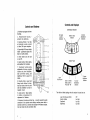
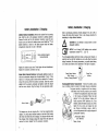
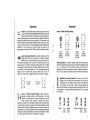
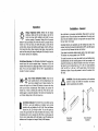
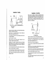
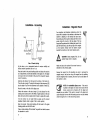
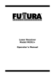
~
<.:! »<
>< >
Laser Receiver
Operating
Instructions
lalA
..
-
~
Contents
Machine Control
I Display Laser Receiver
Contents ...................................................................... 1
Safety ..........................................................................2
System Description ........................................................ 3
Controls and Displays ..................................................... .4
Battery Installation / Charging .......................................... 6
Operation .....................................................................8
Installation and Set-Up ................................................. 11
Specifications .............................................................. 16
Maintenance and Care ............................. .Inside Back Cover
Warranty ............................................... .Inside Back Cover
Safety
Meaning of Symbols:
WARNING: Indicatesa potential hazardoussituation, which
System Description
The laser receiver is a rugged, multipurpose, electronie receiver that
detects laser light generated by rotating laser transmitters. The unit is
designed to work with nearly all makes and models of rotating lasers and
will detect both visible and invisible beams.
could result in death or serious injury.
CAUTION : Indicates a potentially hazardous situation,
which could result in a minor or moderate injury and/or
material, financial, or environmental damage.
NOTE: Important information to enable the product to be
used in a correct and efficient manner unrelated to safety.
The user of this product is expected to follow all operating
and safety instructions of this manual and of the machinery
operator's manual. Perform periodic checks of the product's
performance. The manufacturer or its representatives
assume no responsibility for results of the use of this
product including any direct, indirect, consequential damage, and loss of profits. Check your work frequently.
WARNING: When working near construction or agricultural machinery, follow all safety precautions as described
in the machinery's user manual.
When installed, the operator is given visual indication of the reference
plane of laser light's position relative to the cutting edge of the machine.
The receiver can also be insta lied with a Control Box for automatic control
on certain grading machines. The features and versatility built into the
receiver provide a product that can increase the utilization and productivity of many different types of construction and agricultural machinery.
The operator can customize the settings of the receiver to meet job site
requirements. Settings are provided for adjusting the deadband size or
accuracy, the location of "on-grade" for grading or excavation, the display
for bright or dim conditions, and a laser out-of-Ievel warning.
The super-bright, built-in LED display provides up to 7 channels of grade
elevation position, plus high and low lost beam indications.
'
A tough sealed waterproof housing is designed to work in the tough
machine mounted environment. The electronics are isolated from the
rest of the unit by internal rubber shock-mounts, protecting the unit
from shock and vibration damage.
WARNING: When excavating, follow all excavation and
trench safety regulations and practices.
CAUTION: Be aware of all overhead obstructions and
electrical power lines. The receiver and mast may be higher
than the machinery. Remove when transporting machinery.
CAUTION: Do not disassemble any part of the receiver
other than to replace batteries. The receiver is to be
serviced by authorized service personnel only.
3
2
Controls and Displays
Controls and Displays
lED Status Indicators
1. Aluminum cast upper and lower
housings.
2. Polycarbonate housing protects the electronics.
1
3. Receiving Window - four sets
of photocells equally spaced
to allow 360 degree reception.
2
4. Super-bright lED array is highly
visible - graphically displays the
blade or bucket position.
3
5. Power Switch turns the unit
on and off.
4
6. Grade location, battery status,
and deadband lED indicators.
7. Touchpanel Switches allow
adjustment of accuracy, on-grade
location and plumb indication,
laser out-of-Ievel warning, and
brightness. Refer to page 8 for
details.
LX:::=--W--
5
1-+---1+--
6
8. Mounting Knobs - large, front
facing knobs attached to stainless steel clamps allow for quick
and easy installation to mast or
magnetic mount.
9. Access screws - allows access
to battery compartment for
replacement of batteries.
10. Accessory Connector and Dust Cap - connector accepts the cable
connection to the optional remote display, machine power cabie, or
automatic control box. Connector also accepts Ni-MH battery charger.
Dust cap hel ps keep the connector clean.
On Grade
Location
Indicators
Accuracy
(Deadband)
Indicators
Battery Status
Indicator
Switch Panel
7
8
Laser
Out-of-Level
Center or Offset
Grade Location /
Plumb On - Off
Accuracy
(Deadband)
Seledion
Display
Brightness
Selection
9
10
The initialor default settings when the receiver is turned on are:
laser Out-of-level (OOl)
Grade location
Deadband
Brightness
Off
last Set
last Set
last Set
5
4
Battery Installation
Battery Installation
I Charging
Built-in overcharging protection prevents damage if the unit is left on
charge after being fully charged. There is also charge protection for
attempting to charge alkaline batteries.
Alkaline Battery Installation: Remove the receiver from its carrying
case. Hold the unit 50 the accessory connector is pointing upwards.
Remove the dust cap from the accessory connector. Loosen the two
thumb screws and remove the battery access cover. Install four "C" cell
alkaline batteries as shown on the label diagram inside the battery
compartment noting the (+) and (-) terminals.
+
0c Irl
L.J (1
+
MADE IN USA
SERlAL
+ I
Irlc 0
L::J tJ
I Charging
&
Gf
Battery installation diagram /
Serial number label
CAUTION: Do not attempt to charge alkaline or other
disposable batteries.
NOTE: Do not charge Ni-MH batteries when ambient
temperature exceeds 45 0 C (1130 F).
The rechargeable battery electronics include a charge error indicator. A
solid light on the right LED indicates an error with either the internal
battery connection, the charging temperature, or possible dead battery
cell. Contact your dealer service departmentif this light is displayed.
1+
Replace the battery access cover. Firmly tighten the two thumbscrews.
Replace the accessory connector dust cap.
Charge Status Indicator
Solid - Charging
Blinking - Charging Complete
Nickel Metal Hydride Batteries: Rechargeable batteries require an
initial and subsequent charging time of approximately 3 hours. It may
require 2 or 3 charging cycles to obtain maximum battery life. To charge,
remove the dust cap from the accessory connector. Insert the cannon
adapter into the accessory connector and tighten. Insert the charger
into the cannon adapter. Plug the charger into an appropriate outlet.
1,
Cannon Adapter
GiY
Charger
The batteries mayalso be charged with a 12-volt auto cigarette lighter
adapter. The charge status indicator located on the back of the housing
will remain solid when the unit is charging. The indicator will blink when
fully charged. When charged, unplug the charger from the outlet and
re move the cannon adapter from the accessory connector.
Charge Error
Indicator
Rechargeable Battery Replacement - Remove the battery access
cover. A battery contact is located in the battery housing as iIIustrated.
For proper operation, a negative end of one rechargeable battery must have the protective cover removed
or "skinned" and positioned to touch the contact
in the housing as illustrated. Follow the label
diagram for the other batteries. Replace with
factory approved NiMH batteries only. Once
installed, replace the battery access cover, firmly
tighten the two screws and replace the dust
cap. Charge as instructed on page 6. Refer to
your local requirements for the proper disposal of
rechargeable batteries.
Rechargeable Battery
Cover Removed
Battery Contact
7
6
Operation
Operation
Power: Press the power switch on the touch panel to turn the
unit on. All the LED's wililight briefly and then each LED row wil!
light from top to bottom. This also acts as a check to assure the
display is working properly. On-grade location and deadband settings are
retained from the last time the unit was turned off. If the receiver is out
of the laser beam, the center light will flash to confirm power is on. If the
receiver is in the laser beam, the corresponding LED grade display will be
indicated. To turn the power off, press and hold the power key for
approximately 2 seconds until the LED's are lit, then release the switch.
Center
ON/OFF
I Offset On-Grade Switch:
~
•
1
Out of Level
Enabled
8
Center
On-grade
LED's used
Offset
On-grade
Selected,
PlumbOn
Offset
On-grade
LED's used
.I.
)
~t
•
Plumb Indication: The plumb indication shows when the mast and
receiver are perpendicular to the ground or bevond the deadband range
of +/- 2.5 degrees. The LED's will flash quickly when the boom is
extended, and will flash slowly when the boom is retraeted bevond this
range. The LED display is solid when the boom is within the plumb range.
Out of Level
Disabled
Center I Offset On-Grade Switch: Center on-grade is
selected for typical grading or cut/fill operations. This mode
indicates an equal amount of grade information above and
below on-grade. Offset on-grade is selected when using a
backhoe or excavator. The excavation mode gives more information and
a larger display area above on-grade. This mode also enables the plumb
indication which shows the operator when the mast and receiver are
perpendicular to the ground (plumb) for more accurate grade readings.
Pressing the switch once lights the LED of the current seleetion. Pressing
the switch again while the LED is on changes the seleetion.
•
•
~.
Center
On-grade
Selected,
Plumb Off
~
~
Laser Out-of-Level Switch: Used with rotating lasers that
change their RPM's when out-of-Ievel. This function is always
disabled (off). Pressing this switch once turns the funetion on.
The LED array will display an "X" to confirm it is enabled. When out of the
laser beam, the "X" will flash. When beam strikes greater than 140 RPM
are received, it operates normally. When beam strikes less than 140 RPM
are received, it wil! toggle between an "X" and the appropriate grade
display. To turn the funetion off, press the switch again, and an "X"
without the center LED will display indicating the function is disabled.
•
!
'J
•
•
•
)
Deadband (Accuracy) Switch: Two choices are fine and
standard in the grading mode and standard and wide in the
excavating mode. The LEDs are used to show current seleetion.
This selection and the center / offset on-grade selection will
determine the deadband. Pressing the switch once lights an LED of the
current selection. Pressing the switch again while the LED is on changes
the selection.
I
0
f
Grading
f
Fine
5mm
(0.20")
.I.
I
Standard
12mm
(0.50")
8)
. '··~f
,;
~.
f
Excavating Standard
12mm
(0.50")
.I.
I
Wide
25mm
(1.00")
9
Operation
Display Brightness Switch: Selects the LED display
brightness. Bright and Dim are the options. Use Dim for
normal and lower light conditions and Bright for sunny
, I '
daytime operation if necessary. Display Dim will conserve
battery life by approximately 50%. When the switch is pressed with the
receiver out of the laser beam, the LED's will display a circle with the
current setting. Depress the brightness switch again while the LED's are
lit to change the setting. When receiving a laser beam, simply press the
switch and the setting will change. Viewing the LED's directly in front of
the receiver optimizes the brightness.
-fi-
Out of Beam Indication. The LED display will indicate if the receiver has
moved bevond the vertical reception range. A sequence of LED's wil!
indicate which direction the cutting edge must be moved to pick up the
beam. The out of beam indication will turn off in approximately two
minutes if no beam is received.
.
~
~
~+
; I'
-u- Out of Beam Indication Disable.
Press the two
outer ~witches (Out of Level and Brightness) at the
same time to disable the out of beam indication. The
receiver wil! display the out of beam LED sequence in reverse order from
both top and bottom simultaneously. When disabled, the receiver wil!
indicate out of beam by flashing the center LED. Press the two outer
switches again to enable the indication. The receiver wil! remember the
out of beam display state at the next power up.
Low Battery Indicator: The receiver has a low battery warning
LED th at is used when batteries are installed. During normal
operation with good batteries, the LED is off. When the batteries
become low, the LED will begin to flash. The unit wil! operate as
normal with approximately 90 minutes of battery life remaining. When
the batteries are too low to operate, the LED will be on continuously and
the four corner grade display LED's will toggle on and off indicating the
batteries must be replaced or charged if using Ni-MH batteries.
Installation - General
Set up the laser in a convenient, safe location. Please refer to your laser
operator's man ua I. Ensure the laser is on a stabie tripod. On windy, gusty
days it may be advisable to tie down or weigh down the tripod to make
the laser beam more stabie.
Operating distances are dependent upon the rotating laser power. The
receiver can pick up the beam from all directions (360°), but still requires
a clear line of sight between the laser and receiver.
If your laser has selectabie rotation speeds, select a high rotation speed.
The receiver can process speeds up to 1200 RPM.
To mount the receiver on a mast, turn both the top and bottom knobs
counterclockwise until the mounting clamps in back open enough to fit
around the mounting mast. Place the receiver on the mast. The receiver
wil! mount to round tubing that has a 42 to 50 mm outside diameter.
(1.66" to 2.00") or to 38 mm (1 1/2") square tubing. Turn the knobs
clockwise to tighten. Reverse the process to remove the receiver from
the mast.
WARNING: Follow all safety precautions per the machines
operator's manual and follow all excavation and trench
safety requirements and practices.
I
10
Typical Dozer
Installation
Typical Excavator
Installation
11
Installation - Grading
Laser
Center
On-grade
\,.o.,---""---~"';'II
Installation - Excavating
When using on an excavator or backhoe, the dipperstick should be
vertical and the bucket positioned so it can easily be repeated each time
a grade reading is taken. The bucket can be fully extended, curled, or
levelled, as long as it is consistent wh en grade readings are taken. The
receiver can be set-up in the trench or out of the trench if the cut
elevation can be determined.
Position the machine so the blade is set to the desired finished elevation,
typically on a benchmark or hub stake.
Set the laser up in an appropriate location for receiver visibility and
efficient machine operation and turn it on.
Turn the receiver on, select center on-grade (grading mode) and select
the smallest deadband.
In Trench Set-Up
Position the machine and dig to the desired finished elevation.
Mount the receiver to the mast.
Position the bucket in the grade checking position at the finished elevation.
Slide the receiver up or down until on-grade is indicated. It may be
necessary to adjust the height of the laser.
Set the laser up in an appropriate location for receiver visibility and
efficient machine operation and turn it on.
Alternatively, if the height of instrument (laser beam) to finished
elevation length is known, the receiver can be set by measuring this
distance from the cutting edge of the blade to the center on-grade mark
on the back of the receiver label.
Turn the receiver on and select the offset on-grade and the smallest
deadband.
Face the LED grade display toward the operator and tighten the clamps.
Select the desired deadband and brightness.
The LED grade display will direct the operator which way to move the
blade using the machine's controls to maintain an "on-grade" reading.
Make a sample pass with the blade "on-grade" and check to ensure the
elevation is correct.
12
Mount the mast on the side of the dipper arm.
Place the receiver on the mast, tighten, and adjust the dipper arm so the
receiver is within the plumb range - solid LED's.
Slide the receiver up or down to get an on-grade display then tighten.
(The center on-grade location may be selected and set at this time).
Select the desired deadband and begin to excavate.
Take grade readings with the bucket in the grade checking position and
the LED's solid.
Take a sample reading with the bucket "on-grade" and check to ensure
the elevation is correct.
13
Installation - Excavating
Installation - Magnetic Mount
For excavators and backhoes, determine where the
mount wil! be located on the machine 50 that when the
receiver is attached, it wil! intersect the laser beam.
Ensure the area of the machine is clean and free of oil and
grease. Angle the mount 50 the top edge of the top
mag net will be positioned first. Holding the mount by the
pipe with both hands, place the top edge of the mag net
on the machine. Slowly move the bottom magnet
towards the machine 50 the mount remains plumb.
Laser
\""-----.------.
Excavation
Depth
A,
LU
CAUTION: Strong magnetic field; Do not
position fingers next to mag nets.
Out of Trench Set-Up
Set the laser up in an appropriate location for receiver visibility and
efficient machine operation and turn it on.
Attach and set-up the receiver in the normal manner as
described on the previous pages.
Place the bucket in the grade checking position and situate the machine
a measurement can safely be obtained on the dipper arm. The dipper
arm may be set more horizontal to the ground for convenient measurements if necessary.
Remove the receiver from the mounting pole prior to removing the
magnetic mount. Use the lever to pry the magnet from the machine.
Once the magnetic hold is loosened, the mount can be easily taken off
the machine by hand.
50
Determine the distance from the laser to the bottom of the trench (L).
This is the set-up length. The length is the height of the instrument (Hl)
plus the depth of cut from the benchmark to the bottom of trench (C).
Mount the mast on the side of the dipper arm.
Position the receiver 50 the set-up length (L) is the distance from the
bucket ground contact point to the offset on-grade symbol on the back
label. (Set up to center on-grade symbol if center on-grade wil! be used).
~
NOTE: For extendable dipper arms - if the mast is
mounted to the dipper arm section that moves with the
bucket, grade can be checked with the dipper arm
extended to any position. If the mast is mounted to the dipper arm
section that does not move with the bucket, grade can only be checked
when the dipper arm is in the exact set-up position.
Turn the receiver on and select offset on-grade and the desired
deadband. (Select center on-grade if set to center symbol).
Begin to excavate. Take grade readings with the bucket in the grade
checking position and the LED's solid.
Take a sample reading with the bucket "on-grade" and check to ensure
the elevation is correct.
14
15
Specifications
Beam Reception
360 degrees
Operating Range
610 m (2000 ft.) radius, laser dépendent
Laser RPM
Minimum - 105 ; Maximum - 1200
Vertical Reception
170 mm (6.75")
5 mm
Standard:
(0.20")
12 mm (0.50")
12 mm (0.50")
Wide:
25 mm (1.00")
Any evidence of abuse, misuse, alteration, accident or negligent use or an
attempt to repair products by unauthorized personnel or with parts other
than those provided by the manufacturer automatically voids the warranty.
Fine:
Standard:
Excavator Mode
Plumb Swing Range
Display Output
± 2.5 degrees
Power Supply
Alkaline - 4 x "C" Cell Standard
Bright or Dim
Nickel Metal Hydride - 4 x "C" Cell
Power Cable - 10-30 VDC
Battery Ufe - Alkaline
75 Hours, Display Dim
(Continuous in beam)
50 Hours, Display Bright
Battery Ufe - NiMH
55 Hours, Display Dim
(Continuous in beam)
40 Hours, Display Bright
Battery Recharge Time
3 - 4 hours
Automatic Shut Off
75 minutes with no laser beam
Out of Beam Indication
High and Low
Remote Display Option
Yes
Automatic Control Option
Yes
Dimensions
(LxWxD) 343 x 142 x 149 mm
(13.50" x 5.58" x 5.88")
Mounting Pipe
42 mm to 50 mm O.D. round tube
(1.66" to 2.00") and
38 mm (1 1/2") square tube
Operating Temperature
16
Laser receivers are warranted to be free of defects in material and
workmanship for a period of two years. This warranty period is twentyfour months from the date the product is delivered from the dealer to
the purchaser or is put into service as a demonstration or rental unit.
Please return the included warranty card as this wil[ expedite any
warranty service that may be required. Please retain your warranty
information and proof of purchase. If a warranty card is not on file, proof
of purchase must accompany your request for warranty repair.
Accuracy
Cut / Fill Mode
Warranty
-20 0 to +60 0 C (-4 0 F to +140 0 F)
The user of the product is expected to follow all operating instructions,
periodically checking the instrument and the work as it progresses.
The manufacturers liability under this warranty is limited to repairing or
replacing any product returned to an authorized service center for that
purpose. The foregoing states the entire liability of the manufacturer
regarding the purchase and use of its product and they shall not be held
responsible for any consequential loss or damage of any kind.
This warranty is in lieu of all other warranties, expressed or implied, and
constitutes all of the manufacturers liability with respect to merchandise
sold by it.
Maintenance and Care
Your laser receiver was shipped in a moisture resistant foam padded
carrying case. If the unit is transported from job to job inside its factoryprovided case and normal instrument precautions are followed, the unit
wil! provide many years of service.
Do not wipe dust or dirt off the laser receiver with a dry cloth as scratching
could occur, possibly damaging these surfaces. Use only a good quality
glass cleaner with a soft cloth on all external window surfaces. If these
surfaces have hardened concrete or other materials on them, take the
unit to an authorized service center for clean ing.
If the system will not be used for a 30 day period or more, it is
recommended to remove the batteries from the receiver. Space is
provided in the carrying case for the storage of batteries.
SOKKIA(EUROPE) B.V.
Damsluisweg 1, 1332 EA Almere, The Netherlands
Phone: +31 (0)365322880, Fax: +31 (0)36 5326241
SOKKIA NV/SA
Doornveld Asse 3 Nr 11-B1, 1731 Zellik (Brussel), Belgium
Phone: +32 (0)2-4668230, Fax: +32 (0)2-4668300
SOKKIA SRl, Via Aiserio 22, 20159 Milano, Italy
Phone: +390266-803803, Fax: +390266-803804
SOKKIA BV Ndl. Deutschland
Germany, [email protected]
SOKKIA LTD, Datum House, Electra Way, Crewe Business Park,
CW16ZT CHESHIRE Crewe, United Kingdom
Phone:+44(0)1270-250511,Fax:+44(0)1270~250533
SOKKIA SPOl SRO
Skroupovo namesti 1255/9, 13000 PRAHA 3, Czech Republic
P~one: +42-1-26273715, Fax: +42-1-26273895
SOKKIA (EUROPE) B.V. lst ed. 10-2003
f