1
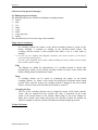
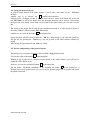
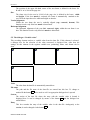
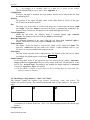
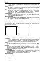
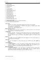
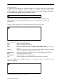
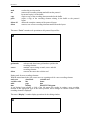
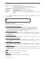
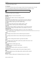
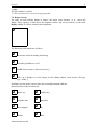
Report Tool
- Protocol Manager -
User manual
Version 2.0
Date of publication:
MESSTECHNIK KLÜGER
Nov. 2001
PROTMAN
2
The application of the software by the user will be effected exclusively on the basis of the
conditions specified hereinafter. Recognition of the conditions will be binding upon opening
the seal of the packaging.
The instructions and specifications contained in this manual can be altered at any time without
giving advance notice. Thus, the Messtechnik Klueger company will not undertake any
obligations. The software and/or databases will be supplied on the basis of a licence contract.
The software and/or databases may only be used in accordance with the terms of contract. No
parts of the user manual and/or the databases may be duplicated or transmitted, neither by
photocopying nor other means of recording, electronically or mechanically, without the prior
written consent of Messtechnik Klueger company.
Licence: The user will be entitled to use a copy of the program (software) with a single
computer. Using the software in this sense means to instal the program in a temporary (RAM)
or permanent memora (hard disk, CD-ROM etc.) or other storage media. Installing the
software on a network server for the sole purpose of distributing it to one or several
computers will not represent proper use as stipulated.
Use in the network: If more than only one user intend to access the program at one and the
same time, a separate program and, thus, a separate licence will have to be purchased for
each of them.
Copyright: By purchasing the program the licensee will acquire possession of the data
carrier, but not of the program itself. The possession of the program will remain with the
licensor or their suppliers and will be protected against illegal copying by copyright.
If the software is not provided with hardware copy protect, either one single copy of the
software will be allowed to be made only for backup or archiving purposes, or the software
will be saved on one single hard disk on condition that the original will be kept only for
backup or archiving purposes. Neither manuals nor other documentation relating to this
software are allowed to be copied.
The user will not be entitled to either lend or let the software. However, the rights resulting
from this licence agreement can be transferred permanently to another person if the assignee
gives his agreement to the stipulations of this licence agreement. The transfer must include
the latest as well as all previous versions.
It is not allowed to develop the program back, to decompile or to disassemble it.
Limited warranty: The manufacturer of the product being the licensor, he warrants, for a
period of 90 days from the date of receipt, that the software functions essentially as described
in the accompanying manual. In case the diskettes are faulty the purchaser may claim for
substitute delivery within 6 months from the delivery date. Any legal warranty and liability
claims towards the retailer who has supplied the software to you will not be replaced nor
restricted thereby. Any other warranty concerning the software, the accompanying manual or
other written documentation will be excluded.
Liability for consequential damages: We herewith point out that, according to the state-ofthe-art, it is not possible to set up software in a way so as to guarantee its impeccable
functioning in all possible combinations and applications. Therefore, the subject-matter of this
licence agreement is to supply a software which is of fundamental use in the sense of the
product description. Neither the licensor nor the supplier can be hold liable for damages
resulting from the use of the software or also from the incapability of using it adequately,
even if the licensor has been informed about the possibility of the occurence of such damage.
In any case, liability will be limited to the amount actually paid for the software. However,
MESSTECHNIK KLÜGER
3
PROTMAN
this exclusion will not be applicable if it can be proved that the damages have resulted from
intentional action or also gross negligence of the licensor.
Further development: The licensor is entitled to update the software at his own discretion
and to develop new or improved versions. Exchanging or updating the software with the
licensee will have to be effected upon request and payment of a fee fixed by the licensor.
Microsoft, Windows and Windows 2000 are registered trademarks of the Microsoft Corporation.
© 2001 Messtechnik Klueger
All rights reserved.
Messtechnik Klueger
Talstrasse 17
98547 Viernau
Tel.: 036847 / 40798
Fax: 036847 / 40797
e-mail:
[email protected]
MESSTECHNIK KLÜGER
PROTMAN
4
1. INTRODUCTION.............................................................................................................................................................. 5
THE PROTOCOL MANAGER „PROT M AN“.............................................................................................................................5
CONVENTIONS FOR USING THE MANUAL .............................................................................................................................5
HARD- AND SOFTWARE REQUIRE MENTS.............................................................................................................................5
2. FIRST STEPS ...................................................................................................................................................................... 6
STARTING THE PROTOCOL MANAGER..................................................................................................................................6
INTERACTION BETWEEN P ROGRAMS AND DATA.................................................................................................................6
3. RECORDING ELEMENTS ............................................................................................................................................ 7
3.1. STATIC TEXT ....................................................................................................................................................................8
3.2. DATA BLOCK ...................................................................................................................................................................8
3.3. VARIABLE TEXT ..............................................................................................................................................................8
3.4. VARIABLE VALUE ...........................................................................................................................................................8
3.5. PAGE NUMBER.................................................................................................................................................................8
3.6. DATE.................................................................................................................................................................................8
3.7. TIME..................................................................................................................................................................................8
3.8. FRAME ..............................................................................................................................................................................8
3.9. LINE ..................................................................................................................................................................................9
3.10. TABLE.............................................................................................................................................................................9
3.11. BITMAP GRAPHICS........................................................................................................................................................9
3.12. DIALTEST GRAPH......................................................................................................................................................9
4. HOW TO USE THE PROTOCOL MANAGER .....................................................................................................10
4.1. EDITING THE PROTOCOL LAYOUT ...............................................................................................................................10
4.2. INSERTING A NEW RECORDING ELEMENT ..................................................................................................................12
4.3. EDITING THE RECORDING ELEMENT ...........................................................................................................................13
4.4. SAVING THE PROTOCOL LAYOUT ................................................................................................................................15
4.5. PREVIEW AND PRINTING OF THE PROTOCOL LAYOUT ..............................................................................................15
5. CHARACTERISTICS OF THE RECORDING ELEMENTS ............................................................................16
5.1. GENERAL REMARKS......................................................................................................................................................16
5.2. SETTING DIALOGUE „STATIC TEXT “...........................................................................................................................16
5.3. THE DIALOGUE “DATA BLOCK”..................................................................................................................................17
5.4. THE DIALOGUE “VARIABLE TEXT “.............................................................................................................................19
5.5. THE DIALOGUE “VARIABLE VALUE”..........................................................................................................................20
5.6. THE DIALOGUE “PAGE NUMBER”, “DATE” AND "TIME".........................................................................................21
5.7. THE DIALOGUE “LINE”.................................................................................................................................................22
5.8. THE DIALOGUE “TABLE”............................................................................................................................................23
5.9. THE DIALOGUE “BITMAP GRAPHICS”........................................................................................................................23
5.10. THE DIALOGUE “DIALTEST DIAGRAM”................................................................................................................24
6. PROGRAM MENUS .......................................................................................................................................................26
7. ICON BAR AND RANGE OF TOOLS .....................................................................................................................30
7.1. ICON BAR........................................................................................................................................................................30
7.2. RANGE OF TOOLS ..........................................................................................................................................................31
MESSTECHNIK KLÜGER
PROTMAN
5
1. Introduction
The protocol manager „ProtMan“
The protocol manager „ProtMan“ is an effective tool for setting up, editing, displaying, and
printing user-specific test logs or measuring protocols. It can be used independently or also in
connection with a data-generating program. In the autonomous mode the protocol manager
works as an independent program. However, it can also be embedded in another software
environment where it can be used as protocol printing or protocol displaying module. The
mouse permits to position and to edit the recording elements very easily. For arranging the
protocol layout a number of various recording elements are available, such as:
?? Static texts
?? Variable texts or values
?? Data blocks
?? Data that can be updated, such as page number, date or time
?? Frame, line, table
?? Bitmap-graphics
?? Various diagrams
For printing variable data (varying texts, measuring values), which can be generated, for
example, by a test or evaluation program, a data file having a given structure must be
available.
Conventions for using the manual
In this manual, the following fonts and symbols are used:
?
This symbol indicates a text containing useful notes to the user.
Italics A text containing useful notes to the user is written in italics.
Bold This typeface is used for marking headings, key combinations, designations of
recording elements as well as setting and input boxes in dialogue windows.
Bold+italics
Menu functions and button designations (buttons) in dialogue windows are written in
bold and italics.
„Normal“
The buttons in the button bar are represented in this way.
„Italics“
Designations of dialogue windows are represented in italics and inverted commas.
Hard- and software requirements
To be able to use the protocol manager effectively, the system components must fulfil the
following minimum requirements:
?? PC with Pentium III processor or higher
?? 32 MB working memory
?? Graphics resolution 1024x768
?? Windows-compatible mouse
?? 20 MB hard disk memory capacity
?? Graphics printer
?? Microsoft Windows 95, 98, NT or 2000
MESSTECHNIK KLÜGER
6
PROTMAN
2. First Steps
Starting the protocol manager
Normally, the program will be start automatic by the program DIALTEST. There for you
have to select a layout file and press the button "edit".
Interaction between programs and data
The figure below illustrates the interaction between programs and data for generating
protocols.
Fig 1 : Interaction between programs and data
A data-generating program ? (e.g. measuring or test program) sets up a data file ? with a
given structure (see Appendix A). The data file is structured like a WINDOWS-INI-file with
sections and entries:
[section 1]
surname=meier
first
name=heinz
...
[section 2]
e1=97.0
...
Structure of a data file
On the basis of the data file, the protocol manager „ProtMan“ ? is able to:
?? set up, edit and save layout files ?,
?? link the layout file and the data file to protocols ? and to print them out via a printer ?.
The configuration files of the protocol manager ? save all current program settings.
MESSTECHNIK KLÜGER
PROTMAN
7
3. Recording elements
When being designed, the structure of a protocol consists of one or several protocol pages
and of the recording elements being located on them (see Fig. 2).
Fig. 2: Design structure of a protocol layout
The following recording elements are available in the editor:
?? static text
?? data block
?? variable text
?? variable value
?? page number
?? date
?? time
?? frame
?? line
?? table
?? bitmap graphics
?? DIALTEST diagram
In what follows, the various available types of recording elements and their characteristics are
described.
MESSTECHNIK KLÜGER
PROTMAN
8
3.1. Static text
The recording element Static text is a text line which appears unchanged in each protocol
print-out, and which can be freely positioned there. It is not affected by the data file.
The text can be provided with a frame within which it can then be aligned. Then, the desired
font and its characteristics can be set (see paragraph 0).
3.2. Data block
The recording element Data block serves to display series of values from the data file (e.g.
measurement series). They are presented in the form of columns in a given range. If the
amount of available data is bigger than the given range, i.e. not all data fit into it, then the
series of values will automatically be continued on the next page within the same range.
Here again, the font and its characteristics can be set (see paragraph 0).
3.3. Variable text
The recording element Variable text uses an entry from the data file and represents this text
in the protocol. As in case of the static text, the characteristics of the recording element can be
set (see paragraph 6.4).
3.4. Variable value
The recording element Variable value also uses a corresponding entry from the data file and
represents it ranged right and formatted (automatic, integer, exponential or in fixed-point
format).
As in case of the static text, the characteristics of the recording element can be set (see
paragraph 6.5).
3.5. Page number
The recording element Page number indicates the current page number on the corresponding
protocol page. The display of the page number can be complemented by a preceding text (e.g.
page).
As in case of the static text, the font and the alignment of the recording element can be set
(see paragraph 6.6).
3.6. Date
The recording element Date determines the current date from the system of the computer and
displays it in the protocol.
As in case of the static text, the font and the alignment of the recording element can be set
(see paragraph 6.7).
3.7. Time
The recording element Time determines the current time from the system of the computer
and displays it in the protocol.
As in case of the static text, the font and the alignment of the recording element can be set
(see paragraph 6.8).
3.8. Frame
The recording element Frame draws a rectangle for framing other recording elements on the
specified protocol page (for setting see paragraph 6.9).
MESSTECHNIK KLÜGER
PROTMAN
9
3.9. Line
The recording element Line permits to draw lines of any length and direction on the specified
protocol page (for setting see paragraph 6.10).
3.10. Table
The recording element Table draws a table grid containing n columns and m lines. It is
used to represent other recording elements in a tabular form.
The recording element can be aligned relative to the page (see also paragraph 6.11).
3.11. Bitmap graphics
The recording element Bitmap graphics is used for representing a graphics which is
available as *.BMP file.
The recording element can be aligned relative to the page (for settings see paragraph 6.12).
3.12. DIALTEST graph
The DIALTEST diagrams are a recording element for the graphical representation of the
results obtained in the dial gauge test, in the dial indicator test (for linear measurement) and
in the lever-type dial test indicator test by means of the DIALTEST program. The following
DIALTEST diagram types are available:
?? total deviation
?? partial measuring range
?? reproducibility
?? hysteresis
?? measuring force
?? total deviation (I)
?? partial measuring range (I)
?? reproducibility (I)
?? hysteresis (I)
?? measuring force (I)
?? total deviation /average (M)
?? partial measuring range /average (M)
?? measuring force /average (M)
?? total deviation /average (I/M)
?? partial measuring range /average (I/M)
?? measuring force /average (I/M)
( I - inverse measuring in case of lever-type dial test indicators )
( M – average value representation )
MESSTECHNIK KLÜGER
PROTMAN
10
4. How to use the protocol manager
4.1. Editing the protocol layout
The following functions are available for editing the recording elements:
?? Select,
?? Edit,
?? Cut,
?? Drag,
?? Copy,
?? Paste,
?? Copy and paste,
?? Delete.
The edit functions can be accessed using various methods.
Using Cursor and mouse:
Select:
For selecting, position the pointer on the desired recording element by means of the
mouse. Selecting is executed by clicking on the left-hand mouse button. The
recording element selected is then provided with either a red or a blue frame as
marking.
? In case of text, bitmap and diagram elements, the entire surface of the object
represents the marking area.
In case of line elements (line, frame, table) marking can only be done on the visible
lines within a pull-in range.
Edit:
The dialogue for editing the characteristics of a recording element is opened after
positioning the pointer on the desired recording element by means of the mouse and
double-clicking on the left-hand mouse button.
Drag:
A recording element can be moved by positioning the pointer on the desired
recording element by means of the mouse and keeping the left-hand mouse button
pressed. Then, using the mouse, the recording element is dragged to the new position
where it is fixed as soon as the left-hand mouse button is released.
Changing the size:
The size of the recording elements can be changed by means of the mouse and the
cursor. After an element has been selected, the cursor is positioned on the corner
points or the lateral borders of the element. When doing so, the cursor changes its
shape into a double-arrow which will point to the direction in which the element can
either be enlarged or reduced, with the left-hand mouse button being kept pressed.
Via the Edit menu:
MESSTECHNIK KLÜGER
11
PROTMAN
The functions of the editing menu always relate to the recording element which has been
selected. They are described below (see context-related menu or button bar).
Via key combinations:
Shift+Del
Ctrl+Ins
Shift+Ins
Ctrl+Del
Del
cut
copy
paste
delete all
delete
The functions are described in the following paragraphs (see context-related menu or button
bar).
Via the context-related menu of the recording element:
The functions of the context-related menu permit to execute the following editing activities:
Edit:
For this purpose, a dialogue window corresponding to the type is opened where all
characteristics of the recording element selected can be set (see paragraph 6
Characteristics of the recording elements).
Cut:
The recording element selected is deleted from the layout and copied into the
clipboard.
Drag:
This function permits to grab the recording element selected with the cursor and to
drag it to any position by moving the mouse. Then, it can be fixed in the current
cursor position by releasing the left-hand mouse button.
Copy-paste:
The recording element selected is copied into the clipboard, with the copy being
flexibly linked with the cursor pointer at the same time. It can be positioned in the
layout by operating the left-hand mouse button.
Delete all:
The complete contents of the protocol layout will be deleted.
Delete:
The delete function serves to remove the recording element selected from the layout
in the editor window.
MESSTECHNIK KLÜGER
12
PROTMAN
Via the buttons of the button bar
The editing buttons that can be found in the button bar fulfill the following functions:
Deleting one or several recording elements selected
Cutting the recording element selected, i.e., the recording element is removed from
the layout and copied into the clipboard
Copying the recording element selected into the clipboard, i.e., the recording
element will be maintained unchanged in the layout, with its copy being put into the
clipboard.
Pasting the recording element contained in the clipboard; In doing so, the recording
element to be inserted can be moved within the layout by means of the cursor. Then,
by clicking on the left-hand mouse button, it is fixed in the current position.
4.2. Inserting a new recording element
Before a new recording element can be inserted, it must be selected either in the toolkit or in
the Tools menu.
The mouse cursor changes its symbol, indicating which recording element is being inserted.
The cursor is then moved, by means of the mouse, to the desired position where the new
recording element is fixed. After this, a corresponding dialogue window is opened where the
characteristics of the object are set. When quitting this window by pressing the OK-key, the
object is positioned in the layout.
?
After a new object has been inserted, the function of the left-hand mouse button is
immediately switched over to the function “Cursor arrow”.
MESSTECHNIK KLÜGER
13
PROTMAN
4.3. Editing the recording element
First step to edit a element is to marking it. A recording element is marked by positioning the
cursor on this very element by means of the mouse and clicking on the left-hand mouse
button. After having done this, a colored frame surrounding the recording element becomes
visible.
? In case of text, bitmap and diagram elements, the whole surface of the object represents
the marking area.
In case of line elements (line, frame, table), however, the marking can only be effected
on the visible lines within a pull-in range.
Several objects can be marked successively by keeping the Shift-key pressed together with
clicking on the left-hand mouse button (e.g. for deleting several objects).
All characteristics of a recording element (e.g. position, size, font etc.) can be changed by
means of the edit function. Each recording element is assigned a dialogue window adapted to
the respective type (see paragraph 6) where any settings can be effected.
?? Opening by double-click:
The edit dialogue is opened by double-clicking on the desired object. Here, the mouse
pointer has to be positioned in the same way as in case of the marking step (see preceding
paragraph).
?? Opening via the context-related menu:
Another way to open the edit dialogue is to mark the recording element by using the lefthand mouse button. Then, the right-hand mouse button is clicked on to open the contextrelated menu where the function Edit
is selected.
?? Cutting via the context-related menu:
The object marked is clicked on by using the right-hand mouse button. Then, select the
function Cut.
?? Cutting via the Edit / Cut menu:
After having marked the desired object, go to Edit / Cut via the menu and activate this
item.
?? Cutting with the button
:
First, mark the desired object. Then, click on the „Cut“ button
in the button bar with
the left-hand mouse button.
?? Dragging with the mouse:
Wanting to move a recording element to another position, you must first position the
cursor on the desired object. By keeping the left-hand mouse button pressed, the recording
element is grabbed by the mouse pointer and can then be dragged with the mouse. When
releasing the mouse button, the object will be dropped on the new position.
?? Dragging via the context-related menu:
If you click on an object in the layout with the right-hand mouse button, its contextrelated menu will be opened. Now, activate the function Drag. The object selected will
then be grabbed by the mouse pointer and can be dragged through the whole layout by
moving the mouse. When the desired position has been reached, the object is fixed by
clicking on the left-hand mouse button. At the same time, the object is detached from the
mouse pointer.
??The object to be dragged remains visible in its original position as long as the new
position is fixed by actuating the left-hand mouse button.
?? Copying and pasting via the context-related menu:
MESSTECHNIK KLÜGER
14
PROTMAN
By pressing the right-hand mouse button, you open the context-related menu of the object
under the cursor of the mouse. Then, select the Copy-Paste function. Now, the layout will
display a copy of the object attached to the cursor of the mouse. This copy can be moved
with the mouse through the layout. By clicking on the left-hand mouse button, the copied
object is inserted in the position of the mouse pointer.
?? Copying and pasting via the das menu Edit:
First, you have to select the object to be copied by clicking on the left-hand mouse button.
Then, select Edit / Copy in the menu. In this step, a copy of the object selected is
deposited in the clipboard. Via the menu function Edit / Paste the copy of the object is
attached to the cursor of the mouse and displayed in the layout. Finally, you can move the
object, by using the mouse, to the desired position where it can be fixed with a mouse
click (left-hand button).
?? Copying and pasting with the buttons
and
:
First, the object to be copied is marked. By actuating the button
(copy) a copy of the
object is put into the clipboard. The button
(paste) attaches the copy to the cursor of
the mouse. By means of the mouse, the copy, which can be seen in the layout, can be
moved to the desired position where it is then fixed by a mouse click.
?? Copying and pasting with key combinations:
For copying the object selected into the clipboard, the key combination Strg+Einfg is
used. The insert mode is enabled by using the key combination Umschalt+Einfg. Then,
the copy is again attached to the cursor of the mouse and can be fixed in the desired
position with the left-hand mouse button.
??The Insert function can be repeated if you want to insert the copy in more than one
position.
?? Deleting via the context-related menu:
By clicking on the right-hand mouse button, the context-related menu for the object in the
range of the cursor of the mouse is opened. The object selected will then be provided with
a colored marking and can be removed from the layout by using the Delete function in the
menu.
?? Deleting via the menu Edit / Delete:
After having marked one or also several objects, select the Edit / Delete function from the
menu for removing the objects selected.
?? Deleting with the button
:
The objects selected can also be deleted by using the button
(delete) in the button bar.
?? Deleting with the button Del:
The Del button of the keyboard deletes all objects selected from the layout.
?? Deleting with the toolbox:
Via the menu Tools / Delete or the button
in the toolbox, it is possible to assign the
delete function to the left-hand mouse button. This change in the function becomes visible
through a mouse cursor symbol consisting of an arrow and a stylized rubber
. If you
now click on an object in the range of the cursor arrow with the left-hand mouse button, it
will be deleted from the layout. The delete functions remains active until it is switched
over via a function of the Tools menu or of the toolbox.
MESSTECHNIK KLÜGER
15
PROTMAN
4.4. Saving the protocol layout
A protocol layout opened in the editor window is saved with a new name via the File/Save
as menu.
Another way is to activate the
button in the button bar.
Following this, a dialogue window is opened where the new name of the layout file in the edit
box File name as well as the target drive and the target directory can be entered. After saving,
the layout file now having a new name can be found in the editor where you can edit it as you
like.
The saving of the layout file to back up any modifications made to an open protocol layout in
the editor window is effected via the File / Save menu.
Another way is to activate the button
in the button bar.
Saving becomes effective when pressing the OK key. When doing so, the edit state saved last
will get lost. By pressing the Cancel key, you can go back to the editor window without any
saving.
After saving, the open layout file can further be edited.
4.5. Preview and printing of the protocol layout
The print preview of a protocol layout is called via File / Page preview menu.
You can also click on the button
in the button bar.
Wanting to get a print-out of a protocol layout opened in the editor window, you will have to
enable the File / Print menu.
However, you can also activate the button
in the button bar.
Via the menu File/Printer installation or by activating the button
in the button bar, a
dialogue box can be opened where you can set up the protocol page(s) to be printed and install
the printer connected.
MESSTECHNIK KLÜGER
PROTMAN
16
5. Characteristics of the recording elements
5.1. General remarks
For setting the characteristics such as position, size, font, type size, frame etc., a
corresponding dialogue window is available for each type of recording element.
The setting
dialogue can be accessed when inserting a new recording element in the layout either to fix its
initial characteristics or – via the function Edit in the context-related menu of an already
existing object – to modify its characteristics.
Types of recording elements:
?? static text
?? data block
?? variable text
?? variable value
?? date
?? page (page number)
?? time
?? frame
?? line
?? table
?? bitmap graphics
?? DIALTEST diagram
On the following pages, the various dialogue windows for setting the characteristics of the
types of recording elements are explained.
5.2. Setting dialogue „Static text“
This element permits to insert a fixed text in the protocol page. The dialogue box is subdivide
into the registers Static text, Positioning, Frame and Format.
Text:
The desired text is entered into the input box.
Position:
In the boxes for X and Y, the position of the top left-hand corner of the text frame is
given in %*100 of the page size.
MESSTECHNIK KLÜGER
PROTMAN
17
Size:
In the boxes Width and Height, the frame size for the text is given in %*100 of the
page size. If the box Match is selected, the frame will automatically be adapted to the
text. In this case, the input boxes for the width and the height are not active.
Vertical alignment:
The text will be aligned vertically within the text frame (at the top, in the middle, at
the bottom). This characteristic is active only when the function Match is disabled.
Horizontal alignment:
Here, the text will be aligned horizontally (range left, centered, range right) within
the text frame. This characteristic is active only when the function Match is disabled.
Frame:
The line width can be entered in the input box Width . However, other features such
as type, line and color are not available in this program version.
5.3. The dialogue “Data block”
It is the purpose of the recording element data block to output series of data from the data file
(e.g. series of measuring data) in columns in a given range. The settings can be performed in
the registers data block, positioning, heading, frame and format..
Section
Enter the section of the data file here in which the data to be displayed exist.
Entry
This box shows the entry in the data file representing the number of data in the data
block. The input having been confirmed by means of OK, the dialogue box opens to
allow the settings for the recording element “data block“ to be edited.
Source
The first and the last of the values to be displayed in the protocol are input in the boxes
1.value and last value.
The box section shows the section of the data file which contains the entry.
Analogously, the box entry shows the data entry belonging to it. Both boxes are also
equipped with the button which allows access to the dialogue box “selection of data
block” described above. These entries can be edited in this manner.
MESSTECHNIK KLÜGER
PROTMAN
?
18
Please, select only those sections as data blocks which contain an entry representing
the number of data in the section (e.g.. n=55) and which contain an appropriate
number of data (see section [FGI] in Appendix A).
Configuration
The start page to display the data concerned in the protocol is entered into this box.
Position
The position of the upper left-hand corner of the data block in %*100 of the page size
is entered into the boxes for X and Y.
Frame size
The frame size of the data block in %*100 of the page size is set in the boxes Width
and Height. If the box match width is activated, the frame is automatically matched
to the max. width of the data depending on the font size. The data block height is not
changed. Then, the input box for width is inactive.
Text alignment
When the box Centre heading is activated, this text is arranged in the centre of the
heading line. Marking the attributes Left, Centre or Right results in an analogous
configuration of the data text. The attributes for the vertical and horizontal alignment
are not available here.
Position of the heading
If the data block extends over several pages, the position of the data block heading on
the first page and the following ones is defined here.
?? “all pages as positioning”
The heading appears on all pages at the position defined.
?? “on page 1 as positionimg – on all the successive pages at the top (heading zone
of 5% )”
The position of the heading is defined on the first page where the data block appears.
On the other pages, the heading is placed at the top after a fixed heading zone of 5% of
the page length.
?? “on page 1 as positionimg – on all the successive pages after heading zone“
The position of the heading is defined on the first page where the data block appears.
On the other pages, the heading is placed at the top after a fixed adjustable heading
zone, with its length being defined in the box “Heading zone” (see next item).
Heading zone
The length of the heading zone for the data block on the following pages is defined
here. It is defined in 1/100 % of the paper length. This function is only active if the
function “on page 1 as positioned – on all the successive pages after heading zone “ in
the box “heading position” is on.
Displaying the heading
There are three choices available. When marking no heading the data block is not
equipped with a header line, marking on all pages results in a header on all pages and
selecting on initial page only the header text is displayed on the first page of the
protocol only.
Heading
The name of the section the data are stored in is displayed, as a default value for the
heading. It is, however, possible to edit any text.
Frame
Selecting the box frame activates the box width where an appropriate frame width is
entered. If this box is deactivated, there is no frame generation around the data output
in the protocol. The attributes type, line and color are not available in this program
version.
Font format
MESSTECHNIK KLÜGER
PROTMAN
19
The font format currently used is displayed here. A dialogue box is available via the
button where the characteristics of the font can be edited.
Line spacing
N-times the space between the lines is set by means of the keys UP and DOWN.
Number format
In the drop-down-menu of this input box you can select between the options
automatic, integer, fixed and exponential. They are defined by means of the UP and
Down keys in the box for the decimal digits. This setting is not available for integer
numbers, if automatic is selected significant digits are entered.
5.4. The dialogue “Variable text“
A variable text is a text element which is retrieved from a data file, and which is then retained
in a measuring protocol. If this element is selected, a dialogue for selecting the section and
entering the variable text in the data file is displayed first. After that, the settings for this
element in the registers variable text, positioning, frame and format can be entered.
Text
The text is automatically entered here from the data file.
File name
Path and data file name are input in this box. To change to another file the button
can be used as well. An appropriate dialogue box is opened.
Section
The data file section which contains the entry with the variable text is shown here. It
can be changed via the button
and the dialogue box which follows.
Entry
This box contains the entry in the data file for the variable text. Analogously to the
section, it can be changed by means of the button
.
??An example of a variable text in a data file is given in the section [TEST
PARAMETER] as entry inr=0-8-15 test gauge in Appendix A.
Position:
MESSTECHNIK KLÜGER
PROTMAN
20
The position of the upper left-hand corner of the text frame is defined in the boxes for
X and Y in %*100 of the page size.
Size:
The frame size for the text in %*100 of the page size is defined in the boxes width
and height. If the box match is activated, the frame is automatically matched to the
text. Then, the input boxes for width and height are inactive.
Vertical alignment:
Within the text frame the text is vertically aligned (top, centered, bottom). This
function is active only if the box match is deactivated.
Horizontal alignment:
The horizontal alignment of the text (left, centered, right) within the text frame is set
here. This function is active only if the box match is deactivated.
5.5. The dialogue “Variable value”
This recording element retrieves a variable value from the data file. If this element is selected,
a dialogue box for the selection of the value concerned is displayed first. After that, the
settings for this element in the registers variable text, positioning, frame, and format can be
done.
Value
The value from the data file is automatically entered here.
File name
The path and the file name of the data file are entered into this box. To change to
another file the button
can be used as well. An appropriate dialogue box is opened
Section
The section of the data file where the entry with the variable value is located is
displayed here. It can be changed by means of the button
and the dialogue box
which follows.
Entry
This box contains the entry of the variable value in the data file. Analogously to the
section, it can be changed via the button
.
MESSTECHNIK KLÜGER
PROTMAN
21
?
An example of a variable value in a data file is given in the section
[TESTPARAMETER] as entry tma=1.40 in Appendix A.
Configuration:
If the box on page is activated, the page number desired can be entered into the input
box belonging to it.
Position:
The position of the upper left-hand corner of the value frame in %*100 of the page
size is entered in the boxes X and Y.
Size:
The frame size of the value in %*100 of the page size is entered into the boxes width
and height. If the box match is activated, the frame is automatically matched to the
character string. In this case, the input boxes for width and height are inactive.
Vertical alignment:
Within the text frame, the character string is vertically aligned (top, centered,
bottom). This feature is only active if the box match is not activated.
Horizontal alignment:
The horizontal alignment of the value within the text frame (left, centered, right) is
set here. This feature is only active if the box match is not activated.
Frame attributes:
The display of the text frame is activated by means of the control box frame. The
input box width allows the line width to be entered. Further attributes such as type,
line and color are not available in this program version.
Font format
The font format currently used is displayed here. The features of the font can be edited
in a dialogue box which appears via the button
.
Number format
In the drop-down menu of this input box you can select from the options automatic,
integer, fixed and exponential. They are set by means of the keys UP and DOWN in the
box for the decimal digits. This setting is not available for integer numbers; if automatic
is selected, significant digits are entered.
??If the number of digits is larger than set, the exceeding digits are truncated. The
value presented is rounded.
5.6. The dialogue “Page number”, “Date” and "Time"
This dialogue contains the registers page number, positioning, frame, and format. The
registers are described below. This element automatically adds a page number to the protocol
pages.
Text
A constant text is shown in the box “Text”. It is always displayed before the current page
number.
Configuration:
MESSTECHNIK KLÜGER
PROTMAN
22
If the box on page is activated, the page number desired can be entered into the input
box belonging to it.
Position:
The position of the upper left-hand corner of the page number frame In %*100 of the
page size is input into the boxes for X and Y.
Size:
The frame size of the character string in %*100 of the page size is entered into the
boxes width and height. If the field match is activated, the frame is automatically
matched to the text. Then, the input boxes for width and height are inactive.
Vertical alignment:
Within the text frame, the text is vertically aligned (top, centre, bottom). This feature
is active only if the box match is deactivated.
Horizontal alignment:
The horizontal alignment of the text (left, centred, right) within the text frame is set
here. This feature is active only if the box match is deactivated.
5.7. The dialogue “Line”
This element allows lines of any length and direction to be drawn. The dialogue includes the
registers line and positioning.
Width
The line width desired is entered into this box.. Further attributes such as type, line and
color are not available in this program version.
Configuration:
If the box on page is activated, the page number desired can be entered into the input
box belonging to it. If on all pages is activated, the input box for the page number is
not active and its data are not effective. The line appears on all pages of the protocol.
Position:
The initial point of the line in %*100 of the page size is defined in the boxes for X and
Y.
Extension:
The distance between the terminating point and the initial point of the line in %*100 of
the page size is defined in the boxes width and height, with width being the horizontal
distance of X and height being the vertical distance of Y.
Vertical alignment:
If vertical alignment is activated, the line is vertically aligned within the page of the
protocol according to the options (top, centre, bottom). Then, the position of Y is
automatically determined. The relevant input box is then not effective.
Horizontal alignment:
MESSTECHNIK KLÜGER
PROTMAN
23
If horizontal alignment is active, the line is positioned within the page of the protocol
according to the option selected (left, centred, right). Then, the position of X is
automatically determined. The input box in Position is not active then.
5.8. The dialogue “Table”
This dialogue contains the registers table, positioning and lines.
Format of the table
The format of the table is defined by means of entering the number of columns and
lines into the boxes concerned.
Configuration:
If the box on page is activated , the page number desired can be entered into the input
box belonging to it. If on all pages is selected, the input box for the page number is
not active and its data are not effective. The table appears on all pages of the protocol.
Position:
The position of the upper left-hand corner of the table in %*100 of the page size is
defined in the boxes for X and Y.
Frame size:
The table size in %*100 of the page size is defined in the fields width and height.
Vertical alignment:
If vertical alignment is activated, the table is vertically aligned within the page of the
protocol according to the options (top, centered, bottom). Then, the position of Y is
automatically determined. The input box concerned is then not effective.
Horizontal alignment:
If horizontal alignment is active, the table is positioned within the protocol page
according to the option selected (left, centered, right). Then, the position of X is
automatically determined. The input box concerned is then not effective.
Width
The width of the table lines is defined here. Further attributes such as type, line and
color are not available in this program version.
5.9. The dialogue “Bitmap graphics”
A bitmap graphics can be integrated into the protocol by means of this element. The graphics
have to be in the format of *.bmp. The dialogue includes the registers bitmap, positioning
and frame.
??The graphics file must not be moved on the data carrier without changing the assignment
in the protocol layout. Otherwise the graphics will not appear in the protocol.
MESSTECHNIK KLÜGER
PROTMAN
24
File
The path and the name of the bitmap file to be integrated into the protocol are entered
into this box. A dialogue box where a bitmap file can be looked for is opened via the
button
. Then, this file together with the path is automatically input into the
box file.
Configuration:
If the box on page is activated, the page number desired can be entered into the input
box belonging to it. If on all pages is active, the input box for the page number is not
active and the input is not effective. The bitmap appears on all pages of the protocol.
Position:
The position of the upper left-hand corner of the bitmap graphics in %*100 of the page
size is defined in the boxes for X and Y.
Size:
The size of the bitmap graphics in %*100 of the page size is defined in the fields
width and height. If page ratio is active, changing one parameter (width or height)
results in matching the other one.
Vertical alignment:
If vertical alignment is activated, the bitmap graphics is vertically aligned within the
page of the protocol according to the options (top, centered, bottom). Then, the
position of Y is automatically determined. The input box concerned is then not
effective.
Horizontal alignment:
If horizontal alignment is active, the bitmap graphics is placed within the protocol
page according to the option selected (left, centered, right). Then, the position of X
is automatically determined. The input box concerned is then not effective.
5.10. The dialogue “DIALTEST diagram”
The DIALTEST diagrams are recording elements for the graphic representation of the test
results by graphs of gauges, dial indicators for linear measurement, or lever type dial
indicators of the DIALTEST program.
Types of the diagram
The following diagram types can be selected from via an integrated pull-down menu :
MESSTECHNIK KLÜGER
PROTMAN
25
?? total deviation
?? partial measuring range
?? reproducibility
?? hysteresis
?? measuring force
?? total deviation (I)
?? partial measuring range (I)
?? reproducibility (I)
?? hysteresis with (I)
?? measuring force (I)
?? total deviation (M)
?? partial measuring range (M)
?? measuring force (M)
?? total deviation (I/M)
?? partial measuring range (I/M)
?? measuring force (I/M)
( I - inverse measurement with lever type dial test indicators )
( M - representation of the mean value )
Axis scaling
Automatic : the scaling is automatically matched to the values to be represented
Factor value: the representation is performed with respect to tolerances given which
are multiplied by a predefined value
Absolute value : the axis scaling is fixed
Representation of curves
The attributes of the curve (dots, continuous line, in black and white, or in colour) can
be determined by selecting the option desired.
Configuration:
If the box on page is selected, the page number desired can be entered into the input
box belonging to it. If on all pages is selected, the input box for the page number is
not active and the entry is not effective. The diagram appears on all pages of the
protocol.
Position:
The position of the upper left-hand corner of the diagram in %*100 of the page size is
defined in the boxes for X and Y.
Frame size:
The size of the diagram in %*100 of the page size is defined in the fields width and
height.
Vertical alignment:
If vertical alignment is active, the diagram is vertically aligned within the page of the
protocol according to the options (top, centre, bottom). Then, the position of Y is
automatically determined. The input box concerned is then not effective.
Horizontal alignment:
If horizontal alignment is active, the diagram is positioned within the protocol page
according to the option selected (left, centred, right). Then, the position of X is
automatically determined. The input box concerned is then not effective.
MESSTECHNIK KLÜGER
PROTMAN
26
6. Program menus
A menu is used to operate the protocol manager. It is located at the top of the program
window and can be operated by means of a mouse or a keyboard, respectively. All functions
of the program can be called up via the menu. The main menu of the program contains the
items file, edit, tools, display, settings, window and help.
The menus also show the key combinations by means of which the editing functions can be
called up directly from the keyboard. The different menus are explained in more detail in the
sections below.
The menu “File” contains file and document operations for protocol layout files.
The meaning of the menu items is as follows:
new
opens a new protocol layout
open
opens an existing protocol layout
close
closes the protocol layout currently existing in the editing window
save
saves the current state on a storage medium without leaving the editing
window
save as
saves the current state under a new file name without leaving the editing
window; the document is edited under the new name
print preview
opens a preview window to display a one- or double-sided protocol layout
print
outputs the protocol to a printer
install printer
opens a dialogue to set the print options
exit
exits the program and requires the changes in the layout to be saved
The menu “Edit” allows editing operations for a recording element in the protocol layout
files to be carried out.
The meanings of the menu items are as follows:
MESSTECHNIK KLÜGER
27
PROTMAN
undo
cut
copy
paste
delete all
delete
revokes the previous action
removes the recording element marked from the protocol
layout and copies it to the buffer
copies a copy of the recording element marked to the buffer
copies a copy of the recording element existing in the buffer to the protocol
layout
deletes the complete contents of the protocol layout
removes one or more recording elements marked from the layout
The menu “Tools” contains tool operations to edit protocol layout files.
grid marks
cursor
delete
activates and deactivates grid marks to position the
recording elements
standard cursor settings to mark, move and edit
recording elements
converts the cursor into a delete tool
Pasting tools for new recording elements:
With the menu items below, the cursor serves as a pasting tool for a new recording element.
static text
data block
variable text
variable value
line
frame
table
page
date
time
bitmap
DIALTEST diagram
A tool having been selected, a click of the left mouse key results in pasting a new recording
element of the appropriate type at the cursor position, and a dialogue to edit the features of the
recording element is displayed.
The menu “Display” contains display operations for the editing window.
MESSTECHNIK KLÜGER
PROTMAN
28
The meanings of the menu items are as follows:
tools
opens a tool box which is floating above the editing window
The box contains those functions available in the menu Tools as well.
layout description not available in this ProtMan version
zoom factor
opens a dialogue to set the size of the display and the
zoom factor, respectively
width of page
The total width of the page can be seen in the editing window.
full page
Matched to the size of the editing window the layout page is completely
displayed.
The menu “Options” contains setting operations for work with the ProtMan program and
layout data sources.
The menu item “Program”
Program settings for five registers are carried out here.
“close ProtMan already opened after query”
ProtMan can be opened several times; if this option is set, a dialogue box appears when
the program is started again asking whether the program used should be closed or not; Yes
closes the version used and opens a new one; No returns to the ProtMan already opened;
Cancel stops the the attempt to open ProtMan a second time.
“recover the working directory”
The working directory used during the previous ProtMan application for the layout files
is used again when the program is started again; otherwise the program directory of
ProtMan is used.
“use previous ZOOM setting”
ProtMan starts the editor with the zoom setting used when the program was left;
otherwise the setting page width is used
“display error list after print or preview”
If this setting is selected, an error list is displayed after the execution of a a print or
preview function showing errors which occurred during the output; otherwise there is no
report available
“save with query before print or preview”
If this setting is selected, it is asked whether a changed layout file should be saved or not
before a print or preview function is executed; otherwise the saving is performed
automatically.
The register ”Drop Mode”
If a ProtMan layout file (*.prt) is drawn in the drag & drop onto the program icon of
PROTMAN.EXE mode by means of the mouse, ”drop mode“ defines which program
function is executed.
“Editor”
Here, a layout file is opened in the editor and can be edited.
“Print”
A layout file is printed out by ProtMan.
“small Preview”
A layout file is opened in the window mode as a small print preview.
MESSTECHNIK KLÜGER
PROTMAN
29
“full-Screen preview”
A layout file is opened in the full-page mode as print preview.
The register ”Raster Marks“
The grid element spacing in vertical and horizontal direction is defined here in mm.
The register “Zoom”
In the editing window, the page width, the full page, or a percentage can be selected. If
page width is selected, the full width of the page can be seen in the editing window. If
full page is active, the layout page is completely displayed matched to the size of the
editing window.
The register “Language”
The languages English or German are available.
The menu “Window” contains operations for configuring and selecting the program
windows.
Cascade
overlapping configuration of the windows as a cascade
Tile
Several windows are displayed side-by-side.
Arrange icons
All windows shown as icons are arranged at a constant distance.
Close
All windows opened are closed.
1 C:\Protocol manager\example.prt
The editing window containing the file example.prt is activated and shown in the
foreground.
The menu “Help” contains operations with on-line-help and any information on the program.
Contents
The subjects to operate the program are called up.
How to use
Recommendations to operate the on-line-help are displayed.
About
A window with information on the program is opened.
MESSTECHNIK KLÜGER
PROTMAN
30
7. Icon bar and range of tools
7.1. Icon bar
The icon bar is located at the top of the program window below the program menu. It is used
to speed up finding and calling up the most important functions by means of a mouse.
The functions of the icons are as follows:
new file
opens the dialogue to create a new layout file
open file
opens a dialogue window to select an existing layout file
save file as
The layout file in the editing window is saved under a new name. Therefore, a
dialogue is opened for the new name and the target directory to be entered.
The editing window remains open to allow further editing.
save file
The current state of the layout file in the editing window is saved.
The editing window remains open thus allowing further editing.
close file
Editing the layout file is finished. The editing window is closed. If the layout has
been modified, a dialogue asks whether the new state should be saved or not.
modify data file
A dialogue is opened to assign another data file as a source of the variable data.
??The variable data are only displayed in the protocol if all sections and entries used so far
exist in the new data file.
delete
The recording element marked is removed from the layout and deleted.
cut
The recording element marked is removed from the layout and copied to the
buffer.
copy
A copy of the recording element marked is generated in the buffer.
paste
The recording element of the buffer is pasted at the position of the mouse cursor
by means of the left mouse key.
undo
The modifications are undone step-by-step.
* search
A recording element is searched for and selected.
* repeat search
The next recording element with the same features is searched for.
install printer
A dialogue to select and install a printer for the protocol output is opened.
print
The protocol with the layout of the editing window and the data file selected is
sent to the printer.
print preview
The one- or double-sided protocol is displayed in the preview window.
MESSTECHNIK KLÜGER
31
PROTMAN
* help
The help window is opened.
?? These functions are currently being prepared.
7.2. Range of tools
The range of tools includes buttons to change the mouse cursor function or to convert the
display. After opening, it floats above the program window and can be reached via the menu
display / tools. It is always located in the foreground.
The functions of the buttons are as follows:
Sets mouse cursor for marking and moving.
Switches grid marks on or off.
Installs mouse cursor as delete tool (eraser).
Calls up a dialogue to set the display of the editing window (zoom factor, full page,
page width...).
Switching over the mouse cursor to place new recording elements within the
layout by means of the left mouse key:
static text
variable text
variable value
data block
not assigned
line
frame
table
MESSTECHNIK KLÜGER
32
PROTMAN
page number
date
time
bitmap graphics
DIALTEST graph
?
A new recording element having been placed, the mouse cursor returns to the marking
and moving mode.
MESSTECHNIK KLÜGER
33
PROTMAN
Appendix A
Example of a Data File
[PRUEFPARAMETER]
date=31.03.1995
time=07:38
pru=Müller-Lüdenscheidt
typ=0
nor=0
art=0
skl=0
inr=14-9-5 Test-Meßuhr
tlg=0.010000
eht=1
mss= -10.987654
msa=0.000000
mse=10.000000
psg=0.100000
atm=1
tma=1.40
tsw=0.010000
wdp=3.000000
wda=5
kma=0.1
uml=1.00
ska=-0.30
ske=0.30
stz=100
skt=1
[DIAGRAMM]
xStart=0
xStop=10
xStep=1
yStart= -25
yStop=25
yStep=5
[SICHTPRUEFUNG]
sip=2
1=2
2=2
3=2
4=2
BEM=Bemerkung-Sichtprüfung
[KENNWERTPRUEFUNG]
kwp=3
fe=3
fg=2
fu=2
ft=2
fw=2
kmax=2
kmin=3
dm=2
fk=2
[TOLERANZEN]
fe=15.000
fg=17.000
ft=5.000
fu=3.000
fw=3.000
kmax=1.500000
kmin=0.300000
dm=0.40000
fk=0.500000
[RESULT]
res=nicht verwendungsfähig
fe=20.00
fg=28.00
fu=8.00
ft=3.00
fw=2.00
kmax=0.00
kmin=0.00
dm=0.00
fk=0.00
feü=-5.00
ftü=fuü=5.00 mm
fgü=?
fwü=entfällt
[FT]
n=11
0=3.00
1=6.00
2=0.00
3=4.00
4=-2.00
5=1.00
6=-3.00
7=-6.00
8=-1.00
9=5.00
10=2.00
MESSTECHNIK KLÜGER
34
PROTMAN
Appendix B
Example of a Layout File
DIAGRAM_FK 6391,8033,1995,1825,-12,2 Arial NOFRAME
STATICTEXT 6981,5657,0,0,-12,2 Arial NOFRAME Abweichungsspanne fk:
DIAGRAM_FW 997,5794,5652,1825,-12,2 Arial NOFRAME
STATICTEXT 997,5657,0,0,-12,2 Arial NOFRAME Abweichungsspanne fw:
STATICTEXT 997,9167,0,0,-6,0 Arial NOFRAME BIGFMS.PRT (c) ajs tui-stz qs/bv
STATICTEXT 1197,8987,0,0,-12,1 Arial NOFRAME und gilt für den Zustand des Meßmittels bei der Prüfung.
STATICTEXT 1197,8850,0,0,-12,1 Arial NOFRAME Die Prüfung erfolgt nach den Richtlinien der VDI/VDE/DGQ 2618 Bl.11
FRAME 997,8805,7979,319,1 NORMALFRAME
VARTEXT 2182,8531,0,0,-12,1 Arial NOFRAME PRUEFPARAMETER pru
STATICTEXT 997,8531,0,0,-12,1 Arial NOFRAME Prüfer:
VARTEXT 2182,8394,0,0,-12,1 Arial NOFRAME RESULT res
STATICTEXT 997,8394,0,0,-12,1 Arial NOFRAME Prüfergebnis:
DIAGRAM_FT 6981,5794,1995,1825,-12,1 Arial NOFRAME
STATICTEXT 6981,5657,0,0,-12,1 Arial NOFRAME Abweichungsspanne ft:
DIAGRAM_FE 997,5794,5652,1825,-12,1 Arial NOFRAME
STATICTEXT 997,5657,0,0,-12,1 Arial NOFRAME Abweichungsspanne fe, fges, fu:
VARVALUE 8644,5201,0,0,-12,1 Arial NOFRAME RESULT fwü %5.1f
VARVALUE 7314,5201,0,0,-12,1 Arial NOFRAME RESULT fw %5.1f
VARVALUE 5984,5201,0,0,-12,1 Arial NOFRAME TOLERANZEN fw %5.1f
STATICTEXT 4388,5201,0,0,-12,1 Arial NOFRAME fw
STATICTEXT 1197,5201,0,0,-12,1 Arial NOFRAME Wiederholbarkeit
VARVALUE 8644,5064,0,0,-12,1 Arial NOFRAME RESULT fgü %5.1f
VARVALUE 7314,5064,0,0,-12,1 Arial NOFRAME RESULT fg %5.1f
VARVALUE 5984,5064,0,0,-12,1 Arial NOFRAME TOLERANZEN fg %5.1f
STATICTEXT 4388,5064,0,0,-12,1 Arial NOFRAME fges
STATICTEXT 1197,5064,0,0,-12,1 Arial NOFRAME Gesamtabweichungsspanne
VARVALUE 8644,4927,0,0,-12,1 Arial NOFRAME RESULT fuü %5.1f
VARVALUE 7314,4927,0,0,-12,1 Arial NOFRAME RESULT fu %5.1f
VARVALUE 5984,4927,0,0,-12,1 Arial NOFRAME TOLERANZEN fu %5.1f
STATICTEXT 4388,4927,0,0,-12,1 Arial NOFRAME fu
STATICTEXT 1197,4927,0,0,-12,1 Arial NOFRAME Meßwertumkehrspanne
VARVALUE 8644,4790,0,0,-12,1 Arial NOFRAME RESULT ftü %5.1f
VARVALUE 7314,4790,0,0,-12,1 Arial NOFRAME RESULT ft %5.1f
VARVALUE 5984,4790,0,0,-12,1 Arial NOFRAME TOLERANZEN ft %5.1f
STATICTEXT 4388,4790,0,0,-12,1 Arial NOFRAME ft
STATICTEXT 1197,4790,0,0,-12,1 Arial NOFRAME Abweichungsspanne
VARVALUE 8644,4653,0,0,-12,1 Aria l NOFRAME RESULT feü %5.1f
VARVALUE 7314,4653,0,0,-12,1 Arial NOFRAME RESULT fe %5.1f
VARVALUE 5984,4653,0,0,-12,1 Arial NOFRAME TOLERANZEN fe %5.1f
STATICTEXT 4388,4653,0,0,-12,1 Arial NOFRAME fe
STATICTEXT 1197,4653,0,0,-12,1 Arial NOFRAME Abweichungsspanne
STATICTEXT 7912,4471,0,0,-12,1 Arial NOFRAME in µm
STATICTEXT 7912,4334,0,0,-12,1 Arial NOFRAME Überschreit.
STATICTEXT 6582,4471,0,0,-12,1 Arial NOFRAME in µm
STATICTEXT 6582,4334,0,0,-12,1 Arial NOFRAME Istwert
STATICTEXT 5253,4471,0,0,-12,1 Arial NOFRAME in µm
STATICTEXT 5253,4334,0,0,-12,1 Arial NOFRAME Sollwert
TABLE 5053,4608,3923,730,3,1,1 NORMAL
TABLE 5053,4288,3923,319,3,1,1 NORMAL
TABLE 997,4608,4056,730,1,1,1 NORMAL
VARVALUE 5479,3832,0,0,-12,1 Arial NOFRAME TOLERANZEN kmax %5.2f
VARVALUE 5479,3695,0,0,-12,1 Arial NOFRAME TOLERANZEN kmin %5.2f
VARVALUE 5479,3558,0,0,-12,1 Arial NOFRAME PRUEFPARAMETER wdp %5.2f
VARVALUE 5479,3422,0,0,-12,1 Arial NOFRAME PRUEFPARAMETER tsw %5.2f
VARVALUE 5479,3285,0,0,-12,1 Arial NOFRAME PRUEFPARAMETER tme %5.2f
VARVALUE 5479,3148,0,0,-12,1 Arial NOFRAME PRUEFPARAMETER tma %5.2f
VARVALUE 5479,3011,0,0,-12,1 Arial NOFRAME PRUEFPARAMETER psg %5.2f
VARVALUE 5479,2874,0,0,-12,1 Arial NOFRAME PRUEFPARAMETER mse %6.2E
VARVALUE 5479,2737,0,0,-12,1 Arial NOFRAME PRUEFPARAMETER msa %5.0f
VARVALUE 5479,2600,0,0,-12,1 Arial NOFRAME PRUEFPARAMETER tlg %.3G
VARVALUE 5455,2464,272,91,-12,1 Arial C00R00B00T08Z00 PRUEFPARAMETER mss %.2f
VARTEXT 6863,2176,988,100,-12,1 Arial C00R00B00T00Z00 PRUEFPARAMETER inr
VARTEXT 1130,1642,0,0,-12,1 Arial NOFRAME PRUEFPARAMETER date
VARTEXT 8311,1642,0,0,-12,1 Arial NOFRAME PRUEFPARAMETER time
STATICTEXT 5585,3832,0,0,-12,1 Arial NOFRAME N
STATICTEXT 5585,3695,0,0,-12,1 Arial NOFRAME N
STATICTEXT 5585,3558,0,0,-12,1 Arial NOFRAME mm
STATICTEXT 5585,3422,0,0,-12,1 Arial NOFRAME mm
STATICTEXT 5585,3285,0,0,-12,1 Arial NOFRAME mm
STATICTEXT 5585,3148,0,0,-12,1 Arial NOFRAME mm
STATICTEXT 5585,3011,0,0,-12,1 Arial NOFRAME mm
STATICTEXT 5585,2874,0,0,-12,1 Arial NOFRAME mm
STATICTEXT 5585,2737,0,0,-12,1 Arial NOFRAME mm
STATICTEXT 5585,2600,0,0,-12,1 Arial NOFRAME mm
STATICTEXT 5585,2464,0,0,-12,1 Arial NOFRAME mm
STATICTEXT 997,3832,0,0,-12,1 Arial NOFRAME Meßkraftmaximum:
STATICTEXT 997,3695,0,0,-12,1 Arial NOFRAME Meßkraftminimum:
STATICTEXT 997,3558,0,0,-12,1 Arial NOFRAME Wiederholbarkeitsprüfung bei:
STATICTEXT 997,3422,0,0,-12,1 Arial NOFRAME Prüfschritt (ft):
STATICTEXT 997,3285,0,0,-12,1 Arial NOFRAME Teilmeßspanne-Ende:
STATICTEXT 997,3148,0,0,-12,1 Arial NOFRAME Teilmeßspanne-Anfang:
STATICTEXT 997,3011,0,0,-12,1 Arial NOFRAME Prüfschritt (fe, fges, fu):
STATICTEXT 997,2874,0,0,-12,1 Arial NOFRAME Prüfende:
STATICTEXT 997,2737,0,0,-12,1 Arial NOFRAME Prüfanfang:
STATICTEXT 997,2600,0,0,-12,1 Arial NOFRAME Skalenteilungswert:
STATICTEXT 997,2464,0,0,-12,1 Arial NOFRAME Meßspanne:
STATICTEXT 997,2190,0,0,-12,1 Arial NOFRAME Identnummer:
STATICTEXT 997,1925,0,0,-12,1 Arial NOFRAME Prüfprotokoll für Meßuhr nach DIN 878
STATICTEXT 4116,1286,0,0,-16,0 Arial NORMALFRAME TU Ilmenau / IPtA Suhl
STATICTEXT 4322,1049,0,0,-16,0 Arial NORMALFRAME Meßuhrprüfung
STATICTEXT 3782,669,2484,163,-20,1 Schrift_0 C03R00B23T04Z00 P R Ü F P R O T O K O L L
PAGE 4500,7700,0,0,-50,0 Arial NORMALFRAME Seite
CONTTEXT 8000,2000,1500,2000,-10,1 Schrift_1 C03R00B23T04Z12 FG1 n
FRAME 0,9000,10000,1000,0 NORMALFRAME
FRAME 0,0,10000,1500,0 C00R00B00T00Z00
FRAME 1000,400,8000,1400,0 C00R00B00T00Z20
LINE 0,10000,10000,-10000,2 NORMAL
LINE 0,0,10000,10000,0 NORMAL
DATE 8000,1000,467,91,-12,1 Schrift_3 C00R00B00T00Z00
TIME 7000,1500,0,0,-10,1 Schrift_1 BOLDFRAME
BMP 2840,670,1200,700,3 NOFRAME e:\pedit\thigreen.bmp
MESSTECHNIK KLÜGER
PROTMAN
BMP 1213,753,1200,700,1 C00R00B00T00Z00 E:\EMP \THIGREEN.BMP
PAGENUMBER 1498,1372,0,0,-20,0 Schrift_0 BOLDFRAME Seite
[Schrift_0]
FaceName=Arial
PointSize=200
Height= -33
Weight=400
Color=0
Italic=0
Underline=0
StrikeOut=0
[Schrift_1]
FaceName=Arial
PointSize=100
Height= -17
Weight=400
Color=0
Italic=0
Underline=0
StrikeOut=0
[Schrift_3]
FaceName=Arial
PointSize=120
Height= -20
Weight=400
Color=0
Italic=0
Underline=0
StrikeOut=0
[Schriften]
Anzahl=3
[Dateien]
Daten=E:\PEDIT\PRUEFDAT.DAT
MESSTECHNIK KLÜGER
35
36
PROTMAN
Appendix C
Command line parameters
To control the program start (eg from another application or from the WINDOWS surface) the
protocol manager can be equipped with the following initial parameters:
/O
printing without dialogue
/P
printing with dialogue
/E
opens the editor with an existing layout
/N
starts a dialogue to generate a new layout file
/M starts a dialogue to open an existing layout file for the editing window
/V opens full-page print preview
/S
opens print preview in a window
/L
enter name of the layout file to be used
Example:
E:\PEdit\PE.EXE /E /LE:\PEdit\bigfms.prt
E:\PEdit\PE.EXEprogram directory and name of the protocol manager
/E
opening the editor at the start
/LE:\PEdit\bigfms.prt
opening the layout file bigfms.prt of the directory E:\PEdit in the editor
MESSTECHNIK KLÜGER