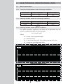
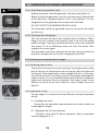
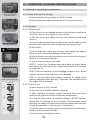
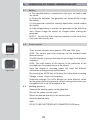
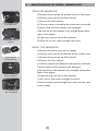
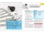
1
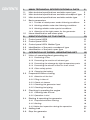
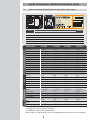
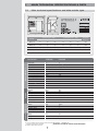
EN
DIESEL GENERATOR
OPEN TYPE-DHY2500L/E DHY4000L/E DHY6000L/E/3
SILENT TYPE-DHY4000SE/3 DHY6000SE/3
WELDER TYPE-DHYW180AC DHYW190AC
USER MANUAL
REVIEW MANUAL CAREFULLY TO AVOID PERSONAL INJURY
MADE UNDER LICENSE OF HYUNDAI CORP. SEOUL, KOREA
PREFACE
Thank you for purchasing HYUNDAI diesel generator.
This operation manual will tell you how to operate and service your HYUNDAI diesel generator set propertly.
Please read this manual before using the generator set to ensure the proper operation.
Follow the instructions to keep your generating set in in the best working conditions and
extend the life of it. If any comments or problem please contact the place where you bought
the generator set or also can contact the manufacturer directly (check contact formular in
last page).
It is also strong recommend that you send the receipt form to the manufactures in order
to register your product for future problems or complains.
All information in this publication is based on the latest product information available at
the time of printing. ITC Power Co.ltd., reserves the right to make changes at any time
without notice and without incurring any obligation. No part of this publication may be reproduced without written permission.
This manual deals with the general items for the HYUNDAI diesel generator set, however
this manual may vary with the development of the product in the future.
This manual should be considered a permanent part of the generator and should remain
with the generator if resold.
Please give special attention to the warnings and cautions. A safety message alerts you
to potential hazards that could hurt you or others. Each safety message is preceded by a
safety alert symbol and one of three words, DANGER, WARNING, or CAUTION.
These signal words mean:
!
DANGER
You CAN be HURT if you don’t follow instructions.
!
WARNING
You CAN be KILLED or SERIOUSLY HURT if you don’t follow
instructions.
!
CAUTION
You CAN be HURT if you don’t follow instructions. Also the machine can be damage
Non respect the instructions explained in this user manual will avoid the guarantee of the
generator set.
Contact Group ITC Power staff for any clarification about the use of the generator here
explained. Contact details in the last page.
1
SAFETY INFORMATION
In order to ensure a safety use of the generator please follow the next safety
instructions:
1.
Check the outside of the generator in order to detect any apparent trouble.
2.
The use or good quality oil and diesel is a must.
3.
Storage should be in a dry place. Frost damage permanently your group.
Drain your machine completely before storing in a dry hot place.
4.
Check and clean filters regularly.
5.
Make sure all subset of the machine are right.
6.
Exhaust fumes contain carbon monoxide, a very dangerous gas, colorless
and odorless, never use the generator in premises or areas closed. Make
sure the group is installed in a location with adequate ventilation or equipped
with a smoke extractor.
7.
The exhaust temperature rises during the use of the group and still burning
even after shutdown. Take care never to touch or move it to store before
being on it is cool enough.
8.
Repair your generator shall be made by a qualified person and trained for this
purpose.
9.
Do not smoke, do not flame or spark when operating or filling the tank, store
the generator near flammable materials.
10.
Store the group in a well ventilated area.
11.
Never transport or store your generator in a horizontal or leaning of fuel leak
and / or oil or will permanently damage your machine.
12.
Never stop the generator when is load applied, be sure to disconnect any
apparatus from the generating set prior start of prior stop.
13.
Do not allow children to operate the engine. Keep children and pets away
from the area of operation.
14.
The engine and exhaust become very hot during operation. Keep the generating set at least 1.5 meter away from buildings and other equipment during
operation. Keep flammable materials away, and do not place anything on the
engine while it is running.
15.
Gasoline is highly flammable and explosive. Turn engine off and let cool
before refueling.
16.
To avoid electric shocks or short circuit, do not touch the generating set
when your hands are wet. This generating set is not water proof, so it should
not be used in a place exposed to rain, snow or water spray. Use of the
generating set in a wet place can cause short circuits and electric shock
during operation.
17.
The generating set must be grounded to prevent electrical shocks from from
faulty appliances. Please connea lenght of heavy wires between the generating set ground terminal and a external ground source
18.
Most applicance motors requiere more than their rated waltage for star-up,
so follow recommendations of your dealer to choose the right power for your
applicance.
19.
Do not exceed the expecific current limit of any socket.
20.
Do not connect directly the generating set to a household circuit.
18.
No guarantee will be covered in case of non-compliance of start-up procedures and safety precautions.
2
CONTENTS
1.
MAIN TECHNICAL SPECIFICATIONS & DATA
5
1.1
Main technical specifications and data open type
5
1.2
Main technical specifications and data soundproof type
6
1.3
Main technical specifications and data welder type
7
1.4
Basic parameters
8
1.4.1
8
Provide of rated power under following conditions
1.4.2 Working reliable under the following conditions
8
1.4.3 Working reliable under special conditions
8
1.4.4 Selection of the right power for the generator
9
1.5
Name identification and name plate
9
2.
IDENTIFICATION OF THE PARTS
10
2.1
Control panel LED3
10
2.2
Control panel LED4
11
2.3
Control panel LED4 Welder Type
12
2.3
Identification of the parts soundproof type
13
2.4
Identification of the parts open type
14
3.
OPERATION OF DIESEL GENERATING SET
15
3.1
Notes of operating diesel generating set
15
3.1.1
15
3.2
Preventing of fire
3.1.2 Preventing the suction of exhaust gas
15
3.1.3 Preventing the damage by high-temperature parts
15
3.1.4 Preventing the electric shock or short circuit
15
3.1.5 Other safety points
15
3.1.6 Charging the battery
15
Preparation before starting
16
3.2.1 Selection of the fuel
16
3.2.2 Filling in lube oil
16
3.2.3 Check air cleaner
17
3.2.4 Checking the generator load
18
3.2.5 Checking fuel piping
18
Checking & operating the engine
18
3.3.1 Checking lube oil level
18
3.3.2 Operation in trial
18
Starting & operating the generator
19
3.4.1 Preparation before starting
19
3.4.2 Starting
19
3.4.3 Make the inspection during the operation.
20
3.5
Adding load
21
3.6
Stop the generator
21
3.3
3.4
3
CONTENTS
3.7
Battery
22
3.8
Control panel
22
3.9
Welding process
22
4.
MAINTENANCE OF DIESEL GENERATING SET
23
Maintenance of diesel generator
23
4.1.1
23
4.1
5.
6.
7.
8.
Change lube oil
4.1.2 Change/clean the element of air cleaner
24
4.1.3 Change fuel filter
26
4.1.4 Check the electrolytic and charge the battery
27
4.1.5 General maintenance
27
LONG TERM STORAGE
TROUBLE SHOOTING AND REMEDY
GUARANTEE
NOTES
28
28
29
30
4
1.
MAIN TECHNICAL SPECIFICATIONS & DATA
1.1
Main technical specifications and data open type
STARTER SW
OFF
DIGITAL PANEL
30mA BREAKER
ON
START
AC230V
PRE.
HEATER
DC 12V 8.3Amp
H
AC230V
FUSE
DC12V 10Amp
FUSE
+
-
W
L
Mod el
Prod uct S ize (m m )
Lengt h
Wid t h
Height
Generator Set
Engine
(mm)
H ei g ht
Pack ag e
M at er i al
DHY2500L
610
460
530
630
480
565
Carton
DHY4000L/E
680
460
560
710
480
600
Carton
DHY6000L/E
720
480
600
740
500
645
Carton
DHY6000L/E-3
720
480
600
740
500
645
Carton
Generator Model
Log.data Alternator
Pack ag i ng Si z e
Leng t h
Width
DHY2500L/E
DHY4000L/E
DHY6000L/E
DHY6000L/E-3
Frequency (Hz)
Rated Power
Max.Power
Voltage (V)
Current (A)
Sockets
Display
Fuel Tank Capacity (L)
Running Time under 50% Load (hr.)
Noise Level behind 7 Meters 50% Load (dBA)
DC Output (V/A) (2)
Battery (Ah)
50 / 60
2 / 2.2 kW
2.2 / 2.4 kW
230 / 120-240
9.6 / 22
2x16A / XX
LED4
14
30 / 27
76.9 / 77.2
12 / 8.3
17
50 / 60
3 / 3.3 kW
3.3 / 3.6 kW
230 / 120-240
14.3 / 30
2x16A / XX
LED4
14
21 / 19
77.1 / 77.4
12 / 8.3
17
50 / 60
5 / 5.5 kW
5.5 / 6.0 kW
230 / 120-240
23.9 / 50
2x16A / XX
LED4
14
13 / 11.5
77.5 / 78
12 / 8.3
36
50 / 60
6.3 / 6.9 kVA
6.9 / 7.6kVA
400 / 120-240
16.2 / 36
1x 16A/3~ & 1x 16A/1~/ XX(1)
LED4
14
13
77.5 / 78
12 / 8.3
36
Engine Type
Engine
Power Output (HP)
Start Method
Displacement (ml)
Oil Capacity (L)
Diesel
D200
4.2
Manual / Elec. start
211
0.75
Diesel
D300
6
Manual / Elec. start
296
1.1
Diesel
D400
10
Manual / Elec. start
418
1.65
Diesel
D400
10
Manual / Elec. start
418
1.65
Alternator
Rated Power (kVA)
Power Factor (Cosφ)
Voltage Regulation
A2-1 / A2.2-1
2 / 2.2
1
AVR
A3-1 / A3.3-1
3 / 3.3
1
AVR
A5-1 / A5.5-1
5 / 5.5
1
AVR
A5-3 / A5.5-3
6.3 / 6.9
0.8
AVR
N.G.(kg)
G.W.(kg)
Loading capacity 20/40/40HQ
55/66
58/69
164/340/340
68/79
72/83
108/222/293
93/108
98/113
102/213/281
93/108
98/113
102/213/281
(1) Single phase socket thermal protected
(2) 100W max. output. 10A fuse protection
Values might vary without prior notice, for updated information please visit our web page
5
1.
MAIN TECHNICAL SPECIFICATIONS & DATA
1.2
Main technical specifications and data soundproof type
30mA BREAKER
INTELLIGENT CONTROLLER
OFF
ON
START
STARTER SW
PRE.
HEATER
EMERGENCY STOP
AC230V
AC230V
DC 12V 8.3Amp
ATS
FUSE
-
H
+
W
L
Model
Product Size (mm)
Length
Width
Height
Generator Set
Engine
(mm)
height
Package
Material
Carton
DHY4000SE
920
520
760
950
570
790
DHY6000SE
920
520
760
950
570
790
Carton
DHY6000SE-3
920
520
760
950
570
790
Carton
Generator Model
Log.data Alternator
Packaging Size
Length
Width
DHY4000SE
DHY6000SE
DHY6000SE-3
Frequency (Hz)
Rated Power
Max.Power
Voltage (V)
Current (A)
Sockets
Display
Fuel Tank Capacity (L)
Running Time under 50% Load (hr.)
Noise Level behind 7 Meters 50% Load (dBA)
DC Output (V/A) (2)
Battery (Ah)
50 / 60
3 / 3.3 kW
3.3 / 3.6 kW
230 / 120,240
14.3 / 30
2X16A / XX
LED4
17
23 / 21
72 / 72.1
12 / 8.3
17
50 / 60
5 / 5.5 kW
5.5 / 6.0 kW
230 / 120,240
23.9 / 50
2x16A / XX
LED4
17
16 / 14.5
72.6 / 72.8
12 / 8.3
36
50 / 60
6.3 / 6.9 kVA
6.9 / 7.6 kVA
400 / 120,240
16.2 / 36
1x 16A/3~ & 1x 16A /1~ / XX(1)
LED4
17
16 / 14.5
72.6 / 72.8
12 / 8.3
36
Engine Type
Engine
Power Output (HP)
Start Method
Displacement (ml)
Oil Capacity (L)
Diesel
D300E
6
Elec. star
296
1.1
Diesel
D400E
10
Elec. start
418
1.65
Diesel
D400E
10
Elec. start
418
1.65
Alternator
Rated Power (kVA)
Power Factor (Cosφ)
Voltage Regulation
A3-1S / A3.3-1S
3 / 3.3
1
AVR
A5-1S / A5.5-1S
5 / 5.5
1
AVR
A5-3S / A5.5-3S
6.3 / 6.9
0.8
AVR
N.G.(kg)
G.W.(kg)
Loading capacity 20/40/40HQ
150
157
68/144/144
160
167
68/144/144
160
167
68/144/144
(1) Single phase socket thermal protected
(2) 100W max. output. 10A fuse protection
Values might vary without prior notice, for updated information please visit our web page
6
1.
MAIN TECHNICAL SPECIFICATIONS & DATA
1.3
Main technical specifications and data welder type
STARTER SW
OFF
DIGITAL PANEL
30mA BREAKER
ON
START
AC230V
PRE.
HEATER
DC 12V 8.3Amp
H
AC230V
FUSE
DC12V 10Amp
FUSE
+
-
W
L
Log.data Alternator
Engine
Generator Set
Model
Product Size (mm)
Length
width
height
Packaging Size (mm)
Length
width
height
Package
Material
DHYW180AC
720
530
580
740
550
610
Carton
DHYW190AC
720
530
580
740
550
610
Carton
Generator Model
DHYW180AC
DHYW190AC
Frequency (Hz)
Rated Power
Max.Power
Voltage (V)
Rated welding current (A)
Rated welding voltage (V)
Display
Fuel Tank Capacity (L)
Running Time under 50% Load (hr.)
Noise Level behind 7 Meters (dBA)
DC Output (V/A) (2)
Battery (Ah)
50
4.5 kW
5 kW
230
12
180
LED4
14
30
77.5
12 / 8.3
36
50
2.5 kW (1)
2.8 kW
230
12
190
LED4
14
30
77.5
12 / 8.3
36
Engine Type
Engine
Power Output (HP)
Start Mothod
Displacement (ml)
Oil Capacity (L)
Diesel
D400
10
Electrical start
418
1.65
Diesel
D400
10
Electrical start
418
1.65
Alternator
Rated Power (kVA)
Power Factor (Cosφ)
Voltage Regulation
A5W
2.5
1
AVR
A5W190
2.5
1
AVR
N.W.(kg)
G.W.(kg)
Loading capacity 20/40/40HQ
110
113
102/213/281
112
115
102/213/281
(1) Can not use welding and power generation at the same time
Designed for professional use in welding
(2) 100W max. output. 10A fuse protection
7
D-diesel engine AC-welder set
Specifications are subject to continuous product delevopment
1.
MAIN TECHNICAL SPECIFICATIONS & DATA
1.4
Basic parameters
1.4.1
Provide of rated power under following conditions
Sea level (M)
Ambient temperature(°C)
0
Relative humidity
20
60%
table 1
1.4.2 Working reliable under the following conditions
Sea level (M)
Ambient temperature(°C)
<1000
5-40
Relative humidity
<90%
table 2
1.4.3 Working reliable under special conditions
For special conditions appliances the power of the generator must be
correct according the bellow formala and table:
Ph = Pn x K1 x K2
Where:
Ph = Power on the requiered height
Pn = Nominal Power
K1 = 1 for use less than 12hr. Day / 0.9 for use over 12hr. Day
K2 = Coeficient according below table
HEIGHT (m.)
K2
0
200
400
600
800
1000
1500
2000
2500
3000
3500
4000
HEIGHT (m.)
K2
0
200
400
600
800
1000
1500
2000
2500
3000
3500
4000
HUMIDITY BETWEEN 0-50%
TEMPERATURE (Celsius)
0
5
10
15
20
25
30
35
40
45
1
0.97
0.94
0.87
0.81
0.75
0.69
0.64
0.59
1
0.87
0.94
0.92
0.85
0.79
0.74
0.68
0.63
0.58
0.98
0.95
0.93
0.9
0.83
0.77
0.72
0.66
0.61
0.56
0.99
0.96
0.94
0.91
0.89
0.82
0.76
0.71
0.65
0.6
0.55
1
0.97
0.94
0.92
0.89
0.87
0.8
0.74
0.69
0.63
0.58
0.53
0.98
0.95
0.92
0.9
0.87
0.85
0.79
0.73
0.67
0.62
0.57
0.52
0.96
0.93
0.9
0.88
0.85
0.83
0.77
0.71
0.65
0.61
0.55
0.5
0.94
0.92
0.89
0.86
0.84
0.81
0.75
0.7
0.64
0.59
0.54
0.49
0.92
0.89
0.87
0.84
0.82
0.79
0.73
0.68
0.62
0.57
0.52
0.47
0.89
0.86
0.84
0.82
0.79
0.77
0.71
0.65
0.6
0.55
0.5
0.46
HUMIDITY BETWEEN 50-100%
TEMPERATURE (Celsius)
0
5
10
15
20
25
30
35
40
45
1
1
1
0.99
0.96
0.93
0.87
0.8
0.74
0.69
0.63
0.58
1
1
0.99
0.97
0.94
0.91
0.85
0.79
0.73
0.67
0.62
0.57
1
1
0.97
0.95
0.92
0.89
0.83
0.77
0.71
0.65
0.61
0.56
1
0.98
0.95
0.93
0.9
0.87
0.81
0.75
0.7
0.64
0.59
0.54
0.99
0.96
0.93
0.91
0.88
0.85
0.79
0.73
0.68
0.62
0.57
0.52
0.96
0.93
0.9
0.88
0.85
0.83
0.77
0.71
0.65
0.6
0.55
0.5
0.94
0.91
0.88
0.86
0.83
0.81
0.75
0.69
0.63
0.58
0.53
0.48
0.91
0.88
0.85
0.85
0.8
0.78
0.72
0.66
0.61
0.56
0.51
0.46
0.88
0.85
0.82
0.8
0.77
0.75
0.69
0.63
0.58
0.53
0.48
0.44
0.84
0.82
0.79
0.77
0.74
0.72
0.66
0.6
0.55
0.5
0.45
0.41
8
table 3
1.
MAIN TECHNICAL SPECIFICATIONS & DATA
1.4.4 Selection of the right power for the generator
To make the right selection of the generator power please note that many
equipments have what is called a pick intensity when start up the machine.
For that reason the nomimal power of the equipmet is not the same as the
nominal power requiered. Please refer to the table bellow for reference but
in any case if you have any doubt tyou can consult with your specialiced
partner dealer, or also can contact the manufacturer for any clarification.
LOAD
MODEL
DHY2500L/E
Home electric appliance, Machine with rectifier type Machine with capacitance
motor
starting type
incandescent lamp.
Projector, electric cooker, Drilling machine, grinding Water pump, air compressor.
machine
T.V., bulb, microwave.
733 W
1760 W
1100 W
DHY4000L/E
DHY4000SE
DHY6000L/E/3
2640 W
1100 W
1650 W
4400 W
1833 W
2750 W
DHY6000SE/3
table 4
!
1.5
CAUTION
Do not connect any equipment that exceed the values above
mentioned.
Name identification and name plate
DHY 6000 LE -3
-3
Single phase
Three phase
Luxury frame Silent frame,Electric start
Power output code
Diesel generator
table 5
All products manufactured from ITC Power under license of HYUNDAI
Corporation, include a name plate on the generator set in order to trace the
production time and the model.
MODEL / SERIAL
POWER Rated-Max.
50
Fig.1 Name Plate
Soundproof type
WEIGHT / DIM.
kW VOLTAGE
kg.
D.
DATE
M.
Y.
IMPORTED BY:
LICENSED BY HYUNDAI CORPORATION, KOREA
Fig.2 Name Plate
Open type
80
9
V
mm.
2.
IDENTIFICATION OF THE PARTS
2.1.1 Control panel LED3 Manual start Open Type CPD41M/CPD42M
1
2
4
3
6
5
7
8
1 panel plate
2 LED3 display
3 thermal breaker
4 CPD41M Single phase socket
CPD42M Three phase socket
5 single phase socket
6 12V connector
7 earth connector
8 10A fuse
2.1.2 Control panel LED3 Electric start Open Type CPD41E/CPD42E
1
2
3
5
4
7
6
9
10
11
8
1 panel plate
2 key contactor
3 LED3 display
4 thermal breaker
5 CPD41E Single phase socket
CPD42E Three phase socket
6 single phase socket
7 pre heater push button
8 ATS connector
9 12V connector
10 earth connector
11 10A fuse
2.1.3 Control panel LED3 Electric start Silent type CPD43E/CPD44E
1
3
4
5
2
6
7
8
9
11
10
10
12
1 panel plate
2 LED3 display
3 key contactor
4 emergency stop button
5 thermal breaker
6 10A fuse
7 earth connector
8 12V connector
9 pre heater push button
10 ATS connector
11 CPD43E Single phase socket
CPD44E Three phase socket
12 single phase socket
2.
IDENTIFICATION OF THE PARTS
2.2.1 Control panel LED4 Manual start Open Type CPD11M/CPD12M
1
2
4
3
6
5
7
8
1 panel plate
2 LED4 display
3 CPD11M 1~.30mA leakage breaker
CPD12M 3~.30mA leakage breaker &
1~thermal breaker for 1~ socket
4 CPD11M Single phase socket
CPD12M Three phase socket
5 single phase socket
6 12V connector
7 earth connector
8 10A fuse
2.2.2 Control panel LED3 Electric start Open Type CPD11E/CPD12E
1
2
3
5
4
7
6
9
10
11
8
1 panel plate
2 key contactor
3 LED4 display
4 CPD11E 1~.30mA leakage breaker
CPD12E 3~ 30mA leakage breaker &
1~thermal breaker for 1~ socket
5 CPD11E Single phase socket
CPD12E Three phase socket
6 single phase socket
7 pre heater push button
8 ATS connector
9 12V connector
10 earth connector
11 10A fuse
2.2.3 Control panel LED3 Electric start Silent type CPD14E/CPD15E
1
3
4
5
2
6
7
8
9
11
10
11
12
1 panel plate
2 LED4 display
3 key contactor
4 emergency stop button
5 CPD14E 1~.30mA leakage breaker
CPD15E 3~ 30mA leakage breaker &
1~thermal breaker for 1~ socket
6 10A fuse
7 earth connector
8 12V connector
9 pre heater push button
10 ATS connector
11 CPD43E Single phase socket
CPD44E Three phase socket
12 single phase socket
2.
IDENTIFICATION OF THE PARTS
2.3.1 Control panel LED4 Welder Type
1
2
3
4
6
5
8
7
9
12
10
11 12
1 panel plate
2 key contactor
3 LED4 display
4 Thermal breaker
5 Single phase socket
6 Welder/Power switch, only for model
DHYW190AC
7 Intensity regulator
8 pre heater push button
9 ATS connector
10 12V connector
11 earth connector
12 10A fuse
2.
IDENTIFICATION OF THE PARTS
2.3
Identification of the parts soundproof type
1
3
2
4
7
5
8
1 fuel level indicator
2 fuel cap
3 lift hook
4 handle
5 air filter cover
6 name plate
7 control panel
8 door for maintenance
9 wheels
6
9
9
3
4
10
3 hook
4 handle
9 wheels
10 muffler output
11 AVR door access
11
9
9
16
12 speed handler
13 oil dipstick
14 oil prime filter
15 oil drain screw
16 battery
12
13
14
15
13
2.
IDENTIFICATION OF THE PARTS
2.4
Identification of the parts open type
3
2
1
4
11
6
7
5
8
9
1 frame
2 fuel level indicatior
3 fuel cap
4 air filter
5 recoil starter
6 injection pump
7 speed handler
8 oil refill / Oil dipstick
9 oil filter
10 oil drainage
11 control panel
10
1
12
13
3
2
14
15
18
16
17
14
2 fuel level indicator
3 fuel cap
12 decompressor acces
13 muffler
14 name plate
15 starter motor
16 oil refil / oil dipstick
17 battery
3.
OPERATION OF DIESEL GENERATING SET
3.1
Notes of operating diesel generating set
Please follow the next notes in order not to get hurt or damage the
generating set.
!
WARNING
!
CAUTION
!
WARNING
3.1.1
Preventing of fire
The engine fuel is light diesel. It is forbidden to adopt gasoline and
kerosene etc. When the oil overflows, please use clean cloth to
remove the oil. It is not permitted to have diesel generator near to
gasoline, kerosene, match and inflammable material, because the
temperature around the muffler is very high when the engine is
operated. For the sake of better ventilation during the generator
operation, the distance between diesel generator and the building
should be more than 1.5 meters. The diesel generator should be
operated on plain ground. Otherwise, the oil will overflow from
diesel generator.
3.1.2 Preventing the suction of exhaust gas
Too avoiding exhaust gas sucked by the person, the diesel generator will be not allowed to work under condition of bad ventilation,
because exhaust gas emitted from the engine includes harmful
CO2.
!
DANGER
3.1.3 Preventing the damage by high-temperature parts
When diesel engine is working, it is not allowed to touch hightemperature parts, such as muffler and its shell etc.
!
WARNING
3.1.4 Preventing the electric shock or short circuit
For avoiding the shock by electricity or short circuit, it is forbidden
to touch with hand the alternator when working. Do not operate the
generator in raining or foggy or close to any water spray. For
preventing the shock by electricity, the grounding should be made,
one end is connected with the grounding terminal of the generator
and another end is connected with the device outside. The grounding terminal of the generator is on control panel.
!
CAUTION
3.1.5 Other safety points
It is very important to know how to stop the generator and the
functions of all switches. Untrained person is not permitted to
operate the generator. The operator should wear safe clothes and
shoes during working.
!
DANGER
3.1.6 Charging the battery
The diesel generator has automatic charging function. The electrolytic liquid of the battery contains the sulfuric acid. For protecting
the human being, should make suitable protection measurement.
As the hydrogen resulting from the battery is of easy explosive gas,
do not smoke when charging. It is not also permitted to make the
spark around the battery. Be sure that there is better ventilation for
charging.
15
3.
OPERATION OF DIESEL GENERATING SET
3.2
Preparation before starting
3.2.1 Selection of the fuel
Only adopt light diesel.Fill in the diesel to fuel tank at full level.
a) Open type:
Fig.3 fuel fill
Soundproof type
Fuel tank
14 L
b) Silent type:
Fuel tank
Fig.4 fuel fill
Open type
17 L
3.2.2 Filling in lube oil
3.2.2.1 Lube oil quality: The qualified lube oil should meet following condition.
ACEA-B2/E2 or higher-grade specification.
API-CD/CE/CF-4/CG-4 or higher-grade specification.
If adopting inferior lube oil, should change the lube oil after every
100 hour operation.
3.2.2.2 Lube oil viscosity
Select lube oil viscosity based on ambient temperature when
starting at cold temperature.
0
14
-10
-4
-20
-22
-30
-40
-40
40
30
10
32
20 W/20
20
50
10W/40
30
68
15W/40
40
86
5W/40
50
104
10W/30
Fig.6 oil fill
open type
°C OIL : SAE...
10 W
°F
122
5W/30
Fig.5 oil fill
Soundproof type
3.2.2.3 Filling in lube oil: Put the generator on plain ground, then fill in lube
oil through the opening of oil dipstick. When checking oil level, only screw
the dipstick into the opening.
!
CAUTION
It is very important to pay attention to lube oil quality, because it will affect
the performance & reliability of the engine. If using inferior lube oil or lube
oil with impurity or not changing lube oil at fixed time, it will cause the
piston to be clipped and make the parts easily worn out, such as cylinder,
bearing, and other moving parts. The engine life will be greatly shortened.
16
3.
!
CAUTION
OPERATION OF DIESEL GENERATING SET
3.2.2.4 Interval for changing lube oil:
First time
30 hours
Next three times
50 hours
Later Every
100 hours
When starting the generator each time, should check oil level. If not
being enough, should add the lube oil to the stipulated level.
Draining off lube oil can be immediately done after engine stopped,
because it is difficult to drain off the oil thoroughly when the engine
is in cold state.
3.2.3. Check the air cleaner
The interval of checking the air filter and clean or replace it depend
if used in dusty emviroments we recommend as follow:
Fig.7 Untight screw
of air filter cover
Clean
100 hours
Replace
500 hours
The process of cleaning the filter element is just with pressure
water, do not use chemical or detergents.
Fig.8 Air filter
element
The Air filter must be complete dry before install again in the machine.
a) Open type:
A.1 Untight the screw from the cover
A.2 Remove the cover
Fig.9 two parts
air filter element
A.3 Remove the Air filter element
A.4 Clean or replace the air filter element
A.5 Place the air filter element again in its original position
A.6 Tight all screw that fix the air element
Fig.10 cover air
filter soundproof
A.7 Place the cover of the air filter and tight the screw.
b) Silent type:
B.1 Remove the cover shown in Fig.10
B.2 Process as the Open type (A.1 to A.7)
B.3 Place the cover
Fig.11 air
filter soundproof
!
CAUTION
B.4 Tight the screws
IT IS FORBIDEN TO RUN THE GENERATOR WITHOUT AIR
CLEANER.
17
3.
!
CAUTION
OPERATION OF DIESEL GENERATING SET
3.2.4. Checking the generator load
Unplug any power from the generator, like lamp and motor etc.
Before starting the generator, must turn off main switch (off position
of the thermal or leakage breaker). If not in this position, it is very
dangerous for the generator to be started with the load.
DO NOT START THE GENERATOR WITH LOAD
Fig.12 30mA leakage
breaker Single phase off
The alternator should be grounded correctly to prevent the shock
by electricity.
3.2.5. Checking the fuel piping
Fig.13 30mA leakage
breaker Three phase off
The fuel and lube oil have been removed prior to delivery. When
filling in the fuel, should check whether there is the air in the piping
before starting. If existing, should drain off the air by unscrewing on
fuel pump till no air bubbling comes out from the diesel, then
retighten the screw again.
This operation should be made only on the first start up or after the
long term storage process or after changing the fuel filter.
Fig.14 air purge over
inlet pipe
3.3 Checking and operating the engine
3.3.1 Checking lube oil level
Fig.15 air purge over
fuel injection pump
Check lube oil level prior to each starting. If the engine works under
lack of lube oil, oil temperature will rise quickly and the engine will
be clipped. If the engine works under enough lube oil, it is very easy
to make lube oil burn, resulting in speed increasingly to damage the
engine. Hence, it is very important to ensure that oil level is between
upper limit and lower limit in oil dipstick. Not need to tight the oil
dipstick to check the oil level. Must be check without screw the
dipstick
3.3.2 Operation in trial
Fig.16 oil dipstick
on diesel engine
For new engine, it is necessary to have 30 hour running-in operation
initially
A Avoiding over-load
During the trial operation, should prevent over-load in order not
to damage the engine
B Changing lube oil at fixed period
Change it after initial 30 hours operation. Refer to operation
manual paragraph 4.1.1
18
3.
OPERATION OF DIESEL GENERATING SET
3.4 Starting & operating the generator
Fig.17 speed handler
at RUN position
3.4.1 Preparation before starting
Put speed handler of the engine at “RUN” position.
Connect battery electrode as when deliver are not connected
3.4.2 Starting
Fig.18 speed handler
at STOP position
3.4.2.1 Manual start
a) Place the circuit or leakage breaker to the off/lower position so
no electric power will be given by the machine
b) Pull the starter grip lightly until you feel resistance and them
relase it.
Fig.19 decompressor
!
CAUTION
c) Press the decompressor on the top of the cylinder head in order
to reduce the pressure in the cylinder and make easyer pull.
d) Pull briskly
f) Do not allow the starter grip to snap back against the engine.
Return it gently to prevent damage to the starter
g) After 3 minutes running the machine move the circuit or thermalbreaker to the on/upeer position
Fig.12 30mA leakage
breaker Single phase off
h) You machine is ready to be used
NOTE 1: If after 3 or 4 attempts the engine does not starts means
that there is air in the fuel circuit, please refer to point 3.2.5 in order
to purge the air.
NOTE 2: Be sure that the circuit or leakage breaker is set in the off
position, otherwise the machine can be damage
Fig.13 30mA leakage
breaker Three phase off
STARTER SW
OFF
ON
NOTE 3: Do not adjust fuel quantity controller or speed limiter
(having adjusted before delivery). Otherwise, the performance of
the engine will be affected.
3.4.2.2 Electric start
a) Insert the key to OFF position
a)
START
b) Turn the key to START position clockwise
ON
c) After starting successfuly, remove the hand from the key to
make the key go back to the ON position automatically.
START
d) If failed to start within 10 seconds holding in START position,
please wait 15 seconds for next starting. If starting motor works
too long, the battery will drop to because the motor to be blocked.
During the operation, let the key be in ON position.
OFF
b)
OFF
ON
c)
START
e) After 3 minutes running the machine move the circuit or thermalbreaker to the on/upeer position
f) You machine is ready to be used
19
3.
OPERATION OF DIESEL GENERATING SET
NOTE 1: If after 3 or 4 attempts the engine does not starts means
that there is air in the fuel circuit, please refer to point 3.2.5 in order
to purge the air.
NOTE 2:Be sure that the circuit or leakage breaker is set in the off
postion, otherwise the machine can be damage
NOTE 3: Do not adjust fuel quantity controller or speed limiter
(having adjusted before delivery). Otherwise, the performance of
the engine will be affected.
3.4.2.2 Remote control Start
a) Place the circuit or leakage breaker to the off/lower position so
no electric power will be given by the machine
b) Leave the Key contactor in OFF position
c) Push the button on the remote control with open lock figure to
start the generator
Fig.20 remote control
d) The generator will start automaticly.
e) After 3 minutes running the machine move the circuit or thermalbreaker to the on/upeer position
f) You machine is ready to be used
NOTE 1: If after 3 or 4 attempts the engine does not starts means
that there is air in the fuel circuit, please refer to point 3.2.5 in order
to purge the air.
NOTE 2: Be sure that the circuit or leakage breaker is set in the off
postion, otherwise the machine can be damage
NOTE 3: Do not adjust fuel quantity controller or speed limiter
(having adjusted before delivery). Otherwise, the performance of
the engine will be affected.
3.4.3 Make the inspection during the operation
a) Check whether there is abnormal sound or strong vibration.
b) Check whether the engine works out of order.
c) Check the color of exhaust gas: black or too white. Black means
the engine is working abnormal or on overload. White means the
mix of air and fuel is not right
3.5
Adding load
a) Add the load according to stipulated data. Please refer to table
4 for detailed loaded data.
20
3.
OPERATION OF DIESEL GENERATING SET
b) The generator should be running at rated speed (leave the
speed handler to “RUN” position). Otherwise, the voltage,
frequency and power will be lower than rated limit, shown in point
1.1 and 1.2
c) When voltage indicating on control panel reaches ±10% of rated
limit, can add the load.
Fig.17 speed handler
at RUN position
d) When connected with the generator, all kinds of machineries
should be by order.
If improper operation, the generator will work out of order. At this
time turn of the circuit thermal or leakage breaker them shut off the
generator switch in time to unload and then check the problem. If
it is overload, should reduce the load. Then start the generator
again a few minutes later. If the indicating of voltage meter is low
or high for a period of more than 10 seconds, must stop the generator for checking.
e) Overload protection. According to the model there is an accurate overload protection over the measurement of the ampere, LED4
equipment. When overload occurs the 30mA leakage breaker
switch to off position. Means that overload has occurred. In that
case reduce the load and turn the 30mA meakage breaker to the
On or upper position. No need to restart the generator.
NOTE 1: Do not start more than two machines in the same time.
Only start them one by one.
NOTE 2: Do not use floodlights with other machines meanwhile.
3.6
Stopping the generator
a) Before stopping the generator stop any machine connected.
Fig.18 speed handler
at STOP position
b) Move the thermal of 30mA leakage breaker to the lower position
so the generator is not giving power.
c) Let the generator run for at least 3 min. without load in orther to
cool it down.
d) Stop the generator
- Manual start: Release the speed controller from RUN to
STOP position by pressing on the side of it.
Fig.12 30mA leakage
breaker Single phase off
- Electric start: Turn the key to the off position
- Remote control: Push the lock open key on the remote
controller.
Fig.13 30mA leakage
breaker Three phase off
e) For Soundproof generator there is an emergency stop button on
the control panel used to stop the generator in case of emergency.
Use it only in case of emergency as if stop the generator with load
can damage the AVR.
21
3.
OPERATION OF DIESEL GENERATING SET
3.7
Battery
a) The standard battery is maintenance free type, no need to add
any liquid.
b) During the operation, the generator can automatically charge
the battery.
c) If the generator is used for stand-by application, should remove
the battery.
d) If the voltage battery is too low, the generator will be difficult to
start. Please charge the battery by charger before starting the
generator.
NOTE 1: Do not start more than two machines in the same time,
Only start them one by one.
3.8
Control panel
There are two kind of control panels, LED3 and LED4 type:
LED3: This control panel has protection for the overload under
thermal breaker.
Fig.21 LED3
The LED display is giving information of the voltage, running hours,
frequency.
LED4: The main feature of this display is the protection of the
overload over the measurement of the current.
Once the display is receiving power will show the different
information of the generator performance.
Fig.22 LED4
By pressing the MODE key will display the information according
Voltage, current, Power and frequency
Protection settings: The LED4 display can settle different values
for the protection of the generator, default setting from factory can
be modified but is not recommentd to do.
3.9
Welding process
Connect the welding cables to the generator
Be sure the cables are not cross
Select the desired intensity in the control panel.
Weld the desired parts.
Note:
DO NOT USE ELECTRODE WITH DIAMETER OVER 4mm.
22
4.
MAINTENANCE OF DIESEL GENERATOR
4.1
Maintenance of diesel generator
For the generator works in order it is very important to perform the
maintenance at fixed period.
The diesel generator is consisted of diesel engine, alternator,
control panel, frame etc. Please read relative manual for the maintenance.
Before maintaining the generator, stop the engine. Please perform
the maintenance in a well ventilated area as the gases and the
exhaust can be harmful.
4.1.1
Change lube oil
To perform the changing of the oil it is recommend to run the
engine at least for 15 min. in order to warm the oil so will be much
more easy to drain it.
The oil of the engine must be change after the first 30 hours of
running and them every 50 hours for the next three time and them
every 100 hours.
Please do not through the oil to normal rubbish can, deposit the
used oil in the appropite oil bin.
Interval for changin the lube oil:
Fig.23 drain oil
open type
First time
30 hours
Next three times
50 hours
Later Every
100 hours
OPEN TYPE GENERATOR:
Fig.24 prime
oil filter screw
a) Place a vessel bellow the oil-drain plug
b) Open the oil dipstick
c) Remove the oil drain plug
d) Let the oil complete flow out of the engine
e) Remove prime oil filter
Fig.25 prime
oil filter
f) Clean the prime oil filter with a brush and diesel
REPLACE PRIME OIL FILTER EVERY 500 hours
g) Screw the oil drain plug
h) Place the prime oil filter in the engine and tight the screw,
be sure the o-ring is not damage
Fig.26 oilil dipstick
i) Fill the engine with new oil. (for oil selection please refer to
point 3.2.2 of this user manual) (for oil capacity please refer
to point 1.1 of this user manual)
23
4.
MAINTENANCE OF DIESEL GENERATOR
j) Check oil level of the engine, to do so check mark on the
oil dipstick. Do not need to tight the oil dipstick to check
level.
k) Tight oil dipstick. Be sure the o-ring is not damage
SILENT TYPE GENERATOR:
a) Place a vessel bellow the oil-drain plug
b) Open the oil dipstick
Fig.27 drain oil
soundproof type
c) Remove the oil drain plug
d) Let the oil complete flow out of the engine
e) Remove prime oil filter
f) Clean the prime oil filter with a brush and diesel
REPLACE PRIME OIL FILTER EVERY 500 hours
Fig.28 prime oil
filter in engine
g) Screw the oil drain plug
h) Place the prime oil filter in the engine and tight the screw,
be sure the o-ring is not damage
i) Fill the engine with new oil. (for oil selection please refer to
point 3.2.2 of this user manual) (for oil capacity please refer
to point 1.1 of this user manual)
Fig.25 prime
p
oil filter
j) Check oil level of the engine, to do so check mark on the
oil dipstick. Do not need to tight the oil dipstick to check
level.
k) Tight oil dipstick. Be sure the o-ring is not damage
4.1.2 Change/clean the element of air cleaner
Fig.26 oilil dipstick
Change or clean the air filter element at the metion period time, in
enviroments dusties or with high humidity is recomended to
perform this maintenance more often. If generator reduces the
power output or shows black smoke please proceed to clean or
replace the air filter element. There is optional a oil bath air filter for
very dusties enviroments. Please ask your dealer for details.
Clean
Fig.9 two parts
air filter element
(everytime perform
the oil change)
First time
30 hours
Replace
100 hours
Next three times
50 hours
500 hours
Later Every
100 hours
500 hours
24
4.
MAINTENANCE OF DIESEL GENERATOR
OPEN TYPE GENERATOR
a) Remove the screw on the outside of the air filter cover
b) Remove the screw on the filter element
c) Remove the filter element
Fig.7 Untight screw
of air filter cover
d) Clean or replace according the maintenance scheudle
e) Never clean the filter element with detergent
f) Be sure the air filter element is dry enought before place
again in the engine
g) Tight the screw on the air filter element
Fig.8 Air filter
element
h) Place the air filter cover and tight the screw
SILENT TYPE GENERATOR
a) Remove the metal cover on the canopy
b) Remove the screw on the outside of the air filter cover
Fig.9 two parts
air filter element
c) Remove the screw on the filter element
d) Remove the filter element
e) Clean or replace according the maintenance scheudle
f) Never clean the filter element with detergent
Fig.10 cover air
filter soundproof
g) Be sure the air filter element is dry enought before place
again in the engine
h) Tight the screw on the air filter element
i) Place the air filter cover and tight the screw
j) Place the metal cover and tight the screw to fix the cover
to the canopy.
Fig.11 air
filter soundproof
25
4.
MAINTENANCE OF DIESEL GENERATOR
4.1.3 Change/clean fuel filter
The generator set has two fuel filters to prevent the impurity of the
diesel to reach the engine.
4.1.3.1 FUEL TANK PRIME FUEL FILTER
This fuel filter must be clean everytime we apppreciate some solid
parts on it. But at least every 500 hours must be remove and clean
with diesel. Never use water to clean any fuel filter
Fig.29 prime fuel filter
soundproof type
a) Remove fuel tank cap
b) Take out the prime fuel filter
c) clean it with diesel fuel
d) place the prime fuel filter again in the fule tank
4.1.3.2 IN LINE FUEL FILTER
This fuel filter must be replace everytime we change the air filter
Fig.30 prime fuel filter
open type
First time
100 hours
Next three times
500 hours
Later Every
500 hours
OPEN TYPE GENERATOR
The fuel filter is placed below the fuel tank, in the hose that goes
from the fuel tank to the engine.
Fig.31 IN LINE
fuel filter
a) Remove the metal brackets from the hose on the injection
valve side in order to drain the fuel in the tank.
b) Drain the fuel in the fuel tank
c) Remove the metal brackets from the hose on both side
of the filter
d) Remove the fuel filter
Fig.32 arrow of
direction detail
e) Place the new fuel filter and pay attention to the arrow
shown on the filter as this filters must be install in the right
direction
f) Tight the brackets on the hose
g) Drain the air in the fuel hose according point 3.2.5
SILENT TYPE GENERATOR
The fuel filter is placed below the fuel tank, in the hose that goes
from the fuel tank to the engine.
a) Open the side door in order to access tot he fuel filter
26
4.
MAINTENANCE OF DIESEL GENERATOR
b) Remove the metal brackets from the hose on the injection
valve side in order to drain the fuel in the tank.
c) Drain the fuel in the fuel tank
Fig.32 arrow of
direction detail
d) Remove the metal brackets from the hose on both side
of the filter
e) Remove the fuel filter
f) Place the new fuel filter and pay attention to the arrow
shown on the filter as this filters must be install in the right
direction
g) Tight the brackets on hose
h) Drain the air in the fuel hose according point 3.2.5
4.1.4 Check the electrolytic and charge the battery
In the generators models with Electric Start the voltage of the
batery must be check in order to be sure that the battery is not
running out.
Check the voltage of the battery
Once a month
The battery used in the generator is a 12V battery but the normal
voltage of it must be over 13V. If voltage is lower than 12V please
proceed to recharge the battery with an external battery charger.
In order not to run out of battery we recommend to perform at
least one start up per week during 30 minutes.
If the generator is not going to be used for longer period please
desconect the battery from the terminal on the battery.
The battery include in the generator is a maintenance free type so
do not need to add the electrolyte
4.1.5 General maintenance
Never incline your generator during the transport when there is oil
in the engine. Non respect of this premise will damage seriously
the engine.
We do recomend to clean the generator after each use and before
long time storage.
Make a visual control of the generator so all the screws and all the
parts as during the use of the generator and because of the vibrations of the machine some parts can be lose.
27
5.
LONG TIME STORAGE
When generator is not going to be used for longer period we
recommned to perform the next operations:
a) Drain the diesel on the fuel tank
b) Drain the oil in the engine
c) Pull the recoil starter until the position that feel resistance so the
intake and exhaust valves will be closed.
d) In the models with electric start remove the connection from the
battery electrode
e) Clean the generator from dust and dirty
When the generator must start again please proceed as explain
before in point 3 of this user manual
NOTE: After long time storage the battery could be empty, please
proceed to recharge before use
6.
TROUBLE SHOOTING AND REMEDY
Causes
No start
of the
Insufficient fuel
Fill in the fuel
Air in fuel circuit
Purge air in fuel circuit
No spray on injector or a little quantity
Repair and adjust the injector
Speed control rod not at “RUN” position
Set control rod to “RUN” position
Check lube oil lever
The level between upper mark “H”
and lower mark “L”
Dirty on the nozzle
Clean the nozzle
No electricity in battery
Charge or change the battery
Not turn on the switch
Turn to “CLOSE” position
Worse contact of the socket
Adjust the socket
Not reach rated speed of the engine
According the stipulation
engine
No output
of generator
Voltage
Remedies
Not reach rated speed of the engine Set speed control rod to operation position.
too low
Check AVR
Adjust the resistance clockwise
(1) lack of the fuel
Automatic
stop after
a certain
time of
operation
(2) lack of lube oil
Repair according to relative
(3) voltage too low/too high
alarming of control panel
(4) frequency too low/too high
(5) over-current
28
7. GUARANTEE
This generators are guaranteed for any failure or defect of fabrication for a period of 1 year or 1000 hours. Non respect of the
instructions in this user manual will avoid the guarantee.
8. NOTES
29
by
MADE UNDER LICENSE OF HYUNDAI CORP. SEOUL, KOREA