1
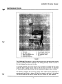
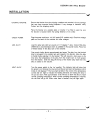
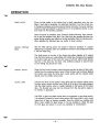
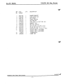
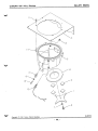
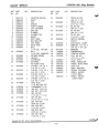
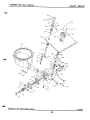
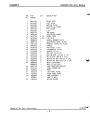
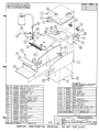
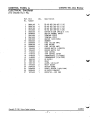
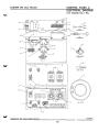
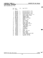
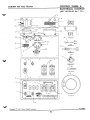
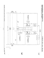
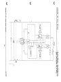
User
Manual
Gerber Coburn
990
Alloy
TM
a GERBER COBURN
990 Alloy Blocker is a trademark of Gerber Coburn, a subsidiary of Gerber Scientific, inc.
A word about Gerber Coburn
CUSTOMER SERVICE (1-800--COBURN-1)
The Gerber Coburn Customer Service organization is an integral part of the Gerber Cobum commitment to
quality. More than just product quality, Gerber Cobum recognizesthe need to address the quality of its service
and delivery systems. The goal is to make it easy to do business with Gerber Cobum.
Gerber Coburn Account Representatives can assist you in:
•
•
Product information
Product availability
•
•
Product ordering
Shipment information
•
•
Billing information
Account information
•
•
•
Warranty and repair information
Replacement parts sales
Hands-on support in every aspect of the business
TECHNICAL SERVICE (1-800-COBURN-’T)
Working hand-in-hand with your Gerber Coburn Account Representative, Technical Service personnel are
available to provide:
•
On-going Gerber Coburn seminars on lens processing and equipment operation and maintenance
•
•
•
Problem solving by phone or in person
Equipment updates and modifications
Technical bulletins
•
Maintenance checklists
Replacement parts information and sales
*
FIELD SERVICE
Gerber Coburn covers all field service or repairs of defective parts while the machine is under the original
warranty. When the warranty expires, if field service is needed for any purpose, such as parts replacement, refurbishing, rebuilding, maintenance or repairs, the service call is subject to an hourly service
charge. All field service requested for Gerber Cobumn equipment not owned by the original purchaser will
be subject to an hourly service charge.
PARTS
An Extended Parts Coverage Plan, available at the time of original purchase or during the first 12 months,
is available on new Gerber Cobum equipment. Your Gerber Coburn sales or field service representative
will be pleased to discuss this economical additional coverage with you.
It is Gerber Cobum’s policy to avoid or minimize downtime in your laboratory operation. Your Gerber
Cobum account representative, backed by technical experts are trained to troubleshoot, service, repair or
update your Gerber Cobum equipment as quickly and efficiently as possible.
Gerber Coburn stocks a complete selection of parts and supplies to keep your Gerber Coburn equipment
operating at peak performance year after year.
GERBER COBURN WORLDWIDE OFFICES AND DISTRIBUTION CENTERS
UNITED STATES
Muskogee, OK
Telephone: (918) 683-4521
Customer Service: 1 -800-262-8761
FacsimIle: 1 -800-262-8760
Technical Service: 1 -800-262-8768
40 Gerber Road East
South Windsor, CT 06074-3248
Telephone: 1-203-648-6600
1-800-843-1479
AUSTRALIA
Lonsdale, South Australia
Telephone: (61) 83821699
Facsimile: (61) 83848661
EUROPE, AFRICA & MIDDLE EAST
The Netherlands
Telephone: (31) 23-52-46124
Facsimile: (31) 23-52-46008
FAR EAST
Republic of Singapore
Carson, CA
Telephone: 1-800-634-2906
(310) 639-1258
Facsimile: (310) 639-1258
Telephone: 65-2538577
Facsimile: 65-2551371
GERMANY, AUSTRIA & SWITZERLAND
Frankfurt, Germany
Telephone: (49) 69-773042
Facsimile: (49) 69-773044
LATIN AMERICA
Miami, FL, I.LS.A.
Telephone: (305) 592-4705
Facimile: (305) 594-9058
CANADA
St. Leonard, Quebec
Telephone: (514) 326-7930
1-800-361-4100 Western Provinces
1-800-361 -7720 Eastern Provinces
Facsimile:
1-800-361-4795
(514) 328-9992
UNITED KINGDOM & IRELAND
Andover, England
Telephone: (44) 1264-332130
Facsimile: (44) 1264-332134
Coburn 800 numbers you may wish to keep handy
1 -800-COBURN-1
Main number for equipment/
parts/supplies
1 -800-COBURN-T
1-800-262-8760
1-800-543-8182
1-800-634-2906
1-800-361-7720
Technical service
Customer service (Fax)
Technical service (Fax)
TlIankj LTOr C/loosing gerber Cobum...
Carson, California
Canada, Eastern Provinces
COBURN 990 Alloy Blocker
TABLE OF CONTENTS
Introduction
1
Installation
2
Operation
3
Alloy Bowl
4
Alloy Spout
5
Cabinet
Control Panel & Electrical Diagram
(110 VAC/60 Hz/i Ph.)
Control Panel & Electrical Diagram
(220 V.AC/50-60 Hz/i Ph.
7
Electrical Schematic
(110 VAC/BO Hz/i Ph.)
Electrical Schematic
9
(220 VAC/50-60 Hz/i Ph.)
Warranty
8
10
COBURN 990 Alloy Blocker
INTRODUCTION
A. work Lamp
B. Alloy Injector Handle
C. Water Cooled Blocking Ring
0. Power On/Off Switch
E. S amp MaIn Power Fuse
F. 1/2 amp System Control Fuse
G. Stem Temperature Control
H. Pot Temperature Control
Alloy Ud
FIGURE 1
The COBURN 99OThMoy Blocker is used to attach the block to the lens blank which provides
a means of holding the lens for surfacing. A low melting point aHoy Is used to provide a
firm bond between the block and the lens.
An especially designed water cooled blocking ring Is furnished to dissipate the heat which
causes the alloy to quickly become solid and affix the block to the lens. An assortment
of rubber seal rings are also provided to allow blocking the different types of lenses.
The machine Is equipped with a low alloy sensor switch. When the alloy level drops to
approxImately three pounds, a beeper will signal the operator to add alloy. It Is Important
that alloy be added at this poInt to prevent slag from entering the stem assembly.
—1
COBURN 990 Alloy Blocker
INSTALLATION
UNCRATE MACHINE
Remove the blocker from the shipping container and examine it for any damage
that may have occurred during shipment. If any damage is detected, notify
Coburn and the shipping carrier.
Place the blocker on a suitable table or counter. If a chiller is used, be sure
the blocker is located within the tubing distance of the chiller.
CHECK POWER
Plug the power cord into a 115 VAC outlet (U.S. models only). Check the voltage
plate on the back of the machine for other voltages.
ADD ALLOY
Load the alloy tank with ten pounds of 117 degree F. alloy. Coburn Blok-Aloy
(#9916-00) is recommended which is available in five-pound blocks. Place two
of these blocks In the alloy tank of the blocker.
One pound of alloy blocks approximately ten lenses. The alloy from the blocked
lens Is recovered in the reclaim tank and reused in the blocker. Allow the alloy
to harder before placing it in the blocker. This will prevent a heat wave on the
lens since the temperature of the alloy from the reclaim tank is much greater
than the blocker. Skim the slag off the top of the molten alloy each time new
alloy is added to the blocker.
HEAT ALLOY
Turn the power switch to the “on” position. The indicator light will show that
the power is on. Remove the cover and set the pot and stem temperature control
knobs to 122 degrees F. The two small red leds in the corner of the temperature
control dial will light to indicate the heating elements are heating the alloy in
the pot and stem. Wait approximately 15-20 minutes to allow the alloy to reach
normal operating temperature. When normal operating temperature is reached,
the red leds will go off. When more heat is needed, they will light again.
-2-
COBURN 990 Alloy Blocker
OPERATION
LENS LAYOUT
Since the final quality of the finished lens Is totally dependent upon the care
taken in each step of surfacing, it is extremely Important to use the utmost care
in the layout procedure so the lens may be blocked correctly. The layout markings
should be clear and distinct to permit the lens to be positioned exactly on axis
and center for the blocking operation.
Once the layout is complete, apply Coburn’s Surface Blocking Tape (#8215000) to the front surface of the lens. This 0.00611 thIck film protects the lens from
abuse during surfacing and affords a thermal protection from the blocking alloy.
When applying the blocking tape, be careful to avoid wrinkles.
INSTALL NESTING
RING
After the initial warmup period, the blocker Is ready for operation. If a special
nesting ring Is required, select one suitable for the lens to be blocked and Insert
it Into the water ring.
The small groove In the face of the nesting ring allows trapped air to escape
from the block cavity as it Is being filled with molten alloy. Excessive force applied
to the lens could seal off this vent and cause an air-lock which would prevent
free flow of the alloy into the block. Only sufficient pressure to seal the lens
to the nesting ring should be used.
INSTALL BLOCK
Place the block onto the water cooled blocking ring with the block’s “Alloy Hole”
located over the neoprene injector spout. Place the tens over the block, aligning
the cylinder axis along the three block center points with the marked center
directly over the middle center point.
BLOCK LENS
Hold the lens firmly in this position using gentle but firm pressure. Gently pump
the alloy Injector handle until the block cavity is full of alloy. Hold slight pressure
until the metal hardens, which is visually detected by the texture of the molten
alloy. The blocked lens may then be removed from the ring and Is ready to
be cribbed or generated.
CAUTION: If glass and plastic lenses both are processed on the same blocker,
it is extremely important to avoid mixing alloys #9915 and #9916, which would
cause both of them to become unusable. Since the #99~6low melting point
alloy Is also suitable for glass lenses, it may be desirable to utilize thIs alloy
for both glass and plastic to avoid any possibility of contamination.
-3-
COBURN 990 Alloy Blocker
ALLOY BOWL
REF. PART
NO. NUMBER
2
3
4
5
6
7
8.
9
10
11
12
13
14
0051100
0369100
0452700
0453200
0453400
0714800
0748700
0759500
0767500
0812900
0827300
0901000
0901300
1148600
2493300
OTY.
DESCRIPTION
1
4
1
1
1
1
1
1
1
1
4
1
1
1
1
BURNER BRACKET
INSULATING PAD
POT COVER
PROBE ADAPTER
MELTING POT
PIPE PLUG (1/8 NPT SOC ND)
WASHER (1/4.)
HEX NUT (~8—32)
HEX ND SCR (1/4—20 X 3/4)
RD ND 5CR (#8—32 X 1—1/4)
BUTTON HO 5CR (1/4—20 X 5/8)
HEATER RING (11OV/500W)
HEATER RING (220V/50D\~)
THERMOCOUPLE
HINGE PIN
~LL00102~
~pyright (C) 1991. ~burr Optica’ Industries
-4-
ALLOY BOWL
COBURN 990 Alloy Blocker
11
3
6
14
5
12
4
8
2
l0
13
9
7
ILLOOIO2
Copyright (C) 1991, Coburn Optical Industries
-4A-
ALLOY SPOUT
REF. PART
NO. NO.
1
2
3
4
5
6
7
8
9
10
11
12
13
14
15
0224700
0369600
0369700
0369800
0369900
0370000
0370100
0370200
0370300
0370400
0404400
0453400
0455100
0455200
0598400
QTY.
1
1
1
1
1
1
1
1
1
1
1
1
1
1
1
16
0599200
1
17
18
19
20
0603600
4299200
0612300
0619500
1
1
1
1
21
0643400
1
22
0643700
1
23
0644000
2
24
0643700
2
25
0714800
1
26
27
28
29
0745500
0758000
0759600
0767800
4
1
2
4
30
0770300
1
31
0778600
2
32
0779400
2
33
0791600
1
34
0792600
2
COBURN 990 Alloy Blocker
DESCRIPTION
REF. PART
NO. NO.
OTY.
INJECTOR NOZZEL
SHAFT
CAM
SPACER
PUMP PLUNGER
CAP EXTENION
END CAP
PLUNGER
PLUNGER PAD
BRACE
SOFT SHOE
MELTING POT
TOP PANEL
MAIN STEM
BALL
(1/4 DIA. TEFLON)
BALL
(1/4 DIA. CARBIDE)
RETURN SPRING
HANDLE
DIAPHRAGM
EXTERNAL
RETAINER RING
0—RING (1/4 ID X
3/8 00 X 1/16)
0—RING (7/16 ID X
5/8 00 X 3/32)
0—RING (9/16 ID X
3/4 00 X 3/32)
0—RING (7/16 ID X
5/8 00 X 3/32)
PIPE PLUG
(1/8 NPT SOC HD)
LOCKWASHER (1/4)
JAM NUT (3/4—16)
HEX NUT (*10—24)
HEX ND SCR
(1/4—20 X 1—1/4)
HEX ND SCR
(5/16—18 X 1—1/2)
SOC CAP SCR
(*10—32 X 5/8)
SOC CAP SCR
(1/4—20 X 5/8)
SOC SET SCR
(*10—32 X 3/16)
SOC SET SCR
(1/4—20 X 1/4)
35
0804400
1
36
0805800
1
37
0812000
2
38
0812200
1
39
0816100
1
40
0838800
1
41
42
0918700
0944500
1
1
43
44
45
46
0977200
1148500
1599700
1823000
1
1
1
2
47
48
49
50
51
52
53
2490800
2493500
2496100
2496700
2498900
2499000
2666000
1
1
1
1
1
1
1
2666200
1
DESCRIPTION
TRUSS HD SCR
(#8—32 X 1/4)
TRUSS HD SCR
(*10—24 X 5/8)
RD HO SCR
(#8—32 X 3/8)
RD HD SCR
(#8—32 X 1/2)
RD HD SCR
(1/4—20 X 3/8)
SWITCH,THERMAL
SAFETY
ELECTRICAL CLAMP
BUSHING (1/2 ID X
5/8 OD X 3/4 LG)
BEARING
THERMOCOUPLE
TORSION SPRING
FLAT HD SCR
(#10—32 X 3/8)
ALLOY SPOUT
PANEL INSULATOR
TARGET BLOCK BASE
AXIS PIN
SHAFT HOUSING
SPRING RETAINER
PENCIL HEATER
(11OV/100W)
PENCIL HEATER
(240V/100W)
ILL006~~
~pyright (C) 1991. Coburn Optical Industries
-5-
COBURN 990 Alloy Blocker
ALLOY SPOUT
18
45
50
Ii
52
31
20
49
13
2?’
12
2
37
38
41
35
29
44
32
53
rr
39
25
6
5
Copyright (C) 1991.
Coburn Optical industries
ILLOQ5Q2
-5A-
CABINET
COBURN 990 Alloy Blocker
REF. PART
NO. NUMBER
DESCRIPTION
1
0452100
1
RIGHT SIDE
2
3
0452200
0452300
1
1
LEFT SIDE
BOTTOM PLATE
4
5
6
7
8
9
10
11
12
13
14
15
16
17
18
19
20
21
22
23.
0452500
0452700
0452800
0455100
0455300
0610700
0615900
0665900
0666700
0667400
0694000
0738700
0746400
0749400
0760200
0767300
0812000
0825800
0826400
0885000
0885400
0897100
0914700
1625500
1663200
1663300
1896900
1896901
2494300
24
25
26
27
28
29
30
Copyright
OTY.
1
1
1
1
1
2 Ft.
3 Ft.
1
1
1
1
6
8
8
1
2
14
14
8
1
1
1
1
4
1
1
1
1
1
ELECTRICAL COVER
POT COVER
LID
TOP PANEL
ELECTRICAL MOUNT
PANEL TRIM
LID TRIM
SERIAL NUMBER PLATE
ELECTRICAL SPEC. PLATE
PRODUCT LIABILITY PLATE
HANDLE
POP RIVET (1/8)
LOCKWASHER (3/16)
WASHER (3/16)
HEX NUT (5/16—18)
HEX ND SCR (1/4~-20 X 1/2)
RD HO 5CR (4*8—32 X 3/8)
BUTTON HO SCR (*8—32 X 1/4)
BUTTON HO SCR (*10—24 X 3/8)
BULB (220V/60W)
BULB (115V/75W)
LAMP MOUNTING BRACKET
CABLE CONNECTOR
FOOT
LEFT—HAND HINGE
RIGHT—HAND HINGE
LAMP ASSEMBLY
LAMP (3—WAY)
SPLASH GUARD
(C) 1991, Coburn Optical Industries
lLLo46o2~
-6-
.:..~
°Tho int,etlon
diwoIwood ho,. i~.to. orlgiatod by
.04 ,. ti.. p.opaty .1 Cobo,•.. Optio.l Iodo.t ri...od.
.n,p4 4, 0...
which coy b. .nro..ly or,nt,1,
Cob,,, Owotlosi
oil
toM. ~I.prl.to.j.,
4.
olow.
a!.. .uowfco+o,ioc cod e.prodüoti ow
,ioht. lii and to ..od Iotopcotcoa cod (hi. d,ooosa(.~
20
19
16
IT
15
IS
14
13
12
II
10
9
&
1’
9
5
4
2
i
a
8
5
I
I
I
I
I
3’
2’
I
I
1
I
I
078T300
Cr60200
Cr49400
Cr46400
OraSroQ
0694000
068T400
0666700
0665900
0625700
0615900
0610700
0455300
0455100
0452800
0452700
0452500
0452300
0452200
i
0452100
LII
ISYM OTY PART NUMBER
I
I
I
SPLIT BALLOONO
TOP RIOtER IS IT~4(Sfl(). BOTTOM NIOtER
IS C&JANTITY REOUIRED IN INDICATED OR
RELATED LOCATION(S).
HEX HO 5CR C 1/4—20 X 1/2)
HEX NUT (5/16—IS)
WASHER (3/16)
LOCKWASHER (3/16)
POP RIVET Cl/a)
HANDLE
PRODUCT LIABILITY PLATE
ELECTRICAL SPEC. PLATE
SERIAL NUMBER PLATE
HOLE PLUG
LID TRIM
PANEL TRIM
ELECTRICAL MOUNT
TOP PANEL
LID
POT COVER
ELECTRICAL COVER
31
1
2494300
SPLASH GUARD
30
30
29
28
I
I
1
I
1896901
1896900
1663300
1883200
LAMP (3—WAY)
LAMP ASSEMBLY
RIGHT—HAND HINGE
LEFt-HAND HINGE
27
4
1625500
FOOT
26
25
24
24
23
22
2)
1
1
1
I
8
14
14
0914700
0897100
0885400
0885000
0826400
0285800
0812000
CABLE CONNECTOR
LAMP MOUNTING BRACKET
BULB (115V/75W)
BULB 122OV/60W)
BUTTON ND SCR (410—24 X 3/B)
BUTTON HO 5CR (48—32 X 1/4)
RD HO 5CR (~8—32 X 3/B)
DESCRIPTION
Sm OTT PART NUMBER
PARTS LIST
COBURN OPTICAL INDUSTRIES
_____________
BOTTOM PLATE
LEFT SIDE
RIGHT SIDE
DESCRIPTION
,~~
——
I
TL~fl.b
ton.,,,
SR
099
___________
ion
000
MAMbO
-
CABINET
~
~
wir4403
~tII2bt
@10*0
1 ~i3flI
A•P000t
IWO. .cdsKooEo.OI(LAH0HA
ILLO46O2
—
COMPANY CONFIDENTIAL ORIGINAL, DO NUT DUPLICATE
CONTROL PANEL &
ELECTRICAL DIAGRAM
(110 VAC/60 Hz.f1 Ph.)
Copyright
(C)
COBURN 990 Alloy Blocker
Ref. Part
No. Number
Qty.
Description
1
2
3
4
5
6
7
8
9
10
11
12
13
14
15
16
17
18
19
20
21
22
23
24
25
26
27
2
4
4
6
6
1
1
1
1
4
1
4
1
1
1
2
2
1
1
1
2
1
2
1
1
1
1
RD HO SCR (*4—40 X 1/4)
RD HD 5CR (*6—32 X 1/4)
RD HD 5CR (*6—32 X 1/2)
RD HO 5CR (*8—32 X 3/8)
BUTTON HD SCR (*6—32 X 1/4)
SWITCH,THERMAL SAFETY
TERMINAL STRIP
TERMINAL STRIP
HEATER (120V/500W)
GROMMET
FUSE (05.000 AMP)
FUSE HOLDER
FUSE (00.500 AMP)
ROCKER SWITCH (LIGHTED)
ROCKER SWITCH CAP
TEMP CONTROL
TEMP CONTROL COVER
THERMOCOUPLE ((J—RING))
THERMOCOUPLE (1/8 PIPE)
DC SUPPLY
RELAY
ALARM, LOW ALLOY
RELAY SOCKET
SPLASH GUARD
PENCIL HEATER (120V/100W)
DC SUPPLY BRACKET
RESISTER, .490 OHM
Q809100
0809700
0810100
0812000
0825300
0838800
0841400
0841500
0901000
0903000
0905800
0908200
0908800
1054500
1054600
1148300
1148400
1148500
1148600
1862300
1061100
1923100
1970800
2494300
2666000
2690400
1870400
1LL08602
1991, Coburn Optical Industries
-7-
COBURN 990 Alloy Blocker
CONTROL PANEL &
ELECTRICAL DIAGRAM
(110 VAC/60 Hz.f1 Ph.)
r
10
3
@27
IC
~I6
$ TEN
THER MC CO U P LS
REC
OH I
010
26
POT
THERMOCOUPLE
20
S
B
4
3
THERMAL SAFETY
$1.1 1CM
P
0
0
l2-~
•1
951
25
0
/1,
Lii
23
9
6543
~2
STEM HEATER
~85
6543
2
3 2 1516
S
‘4
3
2 13 14
0
0
IS
7
POT HEATER
‘3
ILLO 8602
Copyright (C) 1991, Coburn Optical ndustrles
7A
CONTROL PANEL &
ELECTRICAL DIAGRAM
(220 VAC/50-60 Hz./1 Ph.)
Ref. Part
No.
COBURN 990 Alloy Blocker
Oty.
Description
Number
1
2
3
4
5
6
7
8
0809100
0809700
0810100
0812000
0825300
0838800
0841400
0841500
2
4
4
8
6
1
1
1
RD RD 5CR (414—40 X 1/4)
RD HD SCR (#6—32 X 1/4)
RD HD SCR (416—32 X 1/2)
RD RD SCR (418—32 X 3/8)
BUTTON RD SCR (416—32 X 1/4)
SWITCH,THERMAL SAFETY
TERMINAL STRIP
TERMINAL STRIP
9
10
0901300
0903000
1
4
HEATER (220V/500W)
GROMMET
11
12
13
14
0905900
0908200
0908800
1054600
1
4
1
15
1060900
1
1
FUSE (2.5 AMP)
FUSE HOLDER
FUSE (.5 AMP)
ROCKER SWITCH CAP
16
17
18
19
20
21
22
Z3
24
25
26
27
28
1148300
1148400
1148500
1148600
1862300
1862400
i’O61100
1923100
1970800
2494300
2666200
2690400
1870400
2
2
1
1
1
2
2
1
2
1
1
1
1
ROCKER SWITCH (250 V)
TEMP CONTROL
TEMP CONTROL COVER
THERMOCOUPLE
THERMOCOUPLE
DC SUPPLY
TRANSFORMER
RELAY
ALARM, LOW ALLOY
RELAY SOCKET
SPLASH GUARD
PENCIL HEATER (24OV/100W)
DC SUPPLY BRACKET
RESISTER, 490 OHM
1LL08603
Copyright (C) 1991. Coburn Optical Industries
-8-
CONTROL PANEL &
COBURN 990 Alloy Blocker
ELECTRICAL DIAGRAM
(220 VAC/50-60 I-lz./1 Ph.)
10
l0
4
o
12
0
0
95A85
24
THERMAL $ATETI
SWITCH
—
t~
LIL2
1142
krfffl:d
~26
411
~
STEM HEATER
9
~
17181516
0\15
S
1718134
0
0
I
T?~/
j’-..
I
P005/
STIll
POT
‘Os!
TEMPERATuRE CONTROL
7
EED
FUSE
I
2
OrION
FUSE
tS~:7}
~
~
—1
~
~
~wjzr
0
POT HEATER
I
‘3
Copyright
(C) ~991.Coburn Optical Industries
1LL08603
-BA-
0
0
•0
POWER
LI
—
C
0
B
~
FU-l
5 A.
<C,
‘
a:
81.
m
xr
___
N
I
S.
0.
C
=
I
0)
I
—
I
0—
0
N
0,
C
C
—
C)
03
0
C
I
POWER
L3
UN/OFF
-.
I’)
______
1~
‘C
0
0
r
F
(
U,
C
a
0
C)
(
(
(
C)
0
0
0
~0
‘C
U,
(0
C
z
0
Co
Co
I0
CO
0
0
0
C
C
0
0
0
‘-C
LI
0
U,
C,
0)
0
C)
7;.
CD
0
0.
C
40
-I
CD
EG
C/I
-l
—3,
03
3>
r
-L
0
N)
F’)
0
I~1
r
m
C)
C)
CII
12
POWER
ON!OPF
L3~~
9
a
x
N
•0
r’.)
0
C)
r
0
3-.
-k
r
r
-4
(p
C)
I
rn
-I
C)
COBURN PRODUCT WARRANTY
1.
Mt
/2~/J96
WHAT DOES THE COBURN PRODUCT WARRANTY COVER?
Coburn warrants that the product is free from defects in materials and workmanship. A detect exists when a part or
component does not conform with the Cobum specifications as they appear in the owner’s manual.
2. WHAT DOES THE COBURN PRODUCT WARRANTY NOT COVER?
a.
Cobum does not warrant against any problem which results from owner’s failure to properly install, maintain and/or
operate the product in accordance with Cobum’s instructions found in the owner’s manual. All users should be
trained to proper~toperate the equipment in accordance with the owner’s manual and comply with all safely’ precautions.
b. Coburn does not warrant against any problem which results from damage in transit or by casualty, or which results
from misuse or abuse.
c.
Coburn does not warrant against any problem which results from an improper repair or use of an incorrect part or
accessory or which results from service or repair with any part that is not manufactured, sold, or specifically
authorized by Coburn for such use.
d. Coburn does not warrant against any problem which results from Acts of God or voltage power fluctuations or
voltage power failures.
3. WHO IS COVERED BY THE COBURN PRODUCT WARRANTY AND FOR HOW LONG?
a.
The original purchaser of the product from Coburn is entitled to warranty coverage. Except as provided below, new
equipment is warranted for one year from the date of invoice. Remanufactured and/or refurbished equipment is
warranted for 90 days from original installation date. Used equipment is not warranted.
b. Replacement parts are warranted for 90 days. Routine maintenance items, such as; belts, light bulbs, UV bulbs,
chuck pads, air filters, fuses, hoses, hydraulic lines, rubber guards/boots/baffles, nuts, bolts and screws are
warranted for 60 days from original installation date.
c.
Diamond wheels are warranted for 30 days from original installation date.
d.
Cylinder machine pins~anddiamond cutters are determined to be functioning property at the time of installation and
are not covered by the product warranty.
e. For a minimal charge, an extended parts coverage is available for new equipment for the second and third year of
the product life. Contact your Customer Service or Sales Representative.
4. WHAT WILL COBURN DO IF A DEFECT IS COVERED BY WARRANTY?
Technical Service in conjunction with our Field Representative will assist you over the phone to troubleshoot your
problem and determine the best solution for repair or replacement. Cobum will repair or replace, at its option, any part
or component which it determines to be defective.
5. ARE THERE ANY OTHER LIMITATIONS OR EXCLUSIONS RELATED TO THE COBURN WARRANTY?
This written warranty Is In lieu of and excludes all other warranties and representations, expressed or implied,
including, without limitation, any implied warranty of merchantability or fitness for a partIcular purpose; and
the remedy of repair or replacement provided herein is exclusive, and in lieu of any other remedy, including,
without limitation, incidental or consequential damages, even If Coburn has been advised of or can foresee the
possibility of such damages, whether based on contract, negligence, strict liability in tort or other legal theory.
6. WHAT SHOULD I DO TO OBTAIN REPAIR ASSISTANCE OR REPLACEMENT PARTS OR SERVICE AS
COVERED UNDER THIS WARRANTY?
Call 1-800~262-8768and request Technical Service. Be prepared with your account number, serial number of the
machine, and the approximate date of purchase.
7. WHAT IF I HAVE QUESTIONS ABOUT A WARRANTY ISSUE?
Coburn maintains a toll free telephone number (1-800-262-8761) for your convenience. Just tell the Customer Service
Representative that you have a question about your warranty.