1
The 2G Generator
User’s Manual
Rev. 3.292
June 23, 2005
Warnings, Cautions, and Notes
as Used in This Publication
Warning
Warning notices are used in this publication to emphasize that hazardous voltages,
currents, temperatures, or other conditions that could cause personal injury exist in this
equipment or may be associated with its use.
In situations where inattention could cause either personal injury or damage to
equipment, a Warning notice is used.
Caution
Caution notices are used where equipment might be damaged if care is not taken.
Note
Notes merely call attention to information that is especially significant to understanding and
operating the equipment.
This document is based on information available at the time of its publication. While efforts
have been made to be accurate, the information contained herein does not purport to cover all
details or variations in hardware or software, nor to provide for every possible contingency in
connection with installation, operation, or maintenance. National Optronics assumes no
obligation of notice to holders of this document with respect to changes subsequently made.
©Copyright 1998-2005, National Optronics, Inc.
All Rights Reserved.
Preface
Revisions to This Manual
Software versions 3.xx and 4.xx reflect internal hardware differences that are
transparent to the user; that is, screen appearance and machine operation is
identical.
The Communications Screen changed in software versions 2.55 and 3.15. The
fields are similar to those found on the NOP 6E and 4T. For more details, refer to
the end of Chapter 4.
In Version 3.29, there are also changes on the both Lens Material Screens
(formerly called the Blank Materials Screens), as well as a new screen, the Lap
Material Screen.
In the 3.291 edition of the manual was released with Software Version 3.29.
Future software upgrades do not necessarily affect the manual. Call Technical
Support (434) 295-9126) if you feel you need a newer manual.
This edition of the manual (3.292) includes a “General Specifications” section in
Chapter 1.
Related Publications
The Optronics 4T User’s Manual
The Optronics 6E User’s Manual
iii
Preface
iv
Contents
Chapter 1
Before You Begin ................................................................................................ 1-1
Before You Begin ............................................................................................................. 1-1
For Further Assistance ............................................................................................... 1-1
To Order Parts: ...................................................................................................1-1
For Technical Assistance:...................................................................................1-2
Requirements for Use................................................................................................. 1-2
115 VAC 60 Hz 20A Electrical Supply .....................................................................1-2
Operating Conditions .................................................................................................1-2
General Specifications ............................................................................................... 1-3
Dimensions ................................................................................................................1-3
Cutters........................................................................................................................1-3
Cutter Motor ..............................................................................................................1-3
Vacuum......................................................................................................................1-3
Lens Materials............................................................................................................1-3
Certifications..............................................................................................................1-3
Statement Against Misuse..........................................................................................1-3
Installation Procedures ..................................................................................................... 1-4
2G Boot-Up Sequence ...................................................................................................... 1-8
The First Time After a Black Box Is Installed....................................................1-8
Chapter 2
Entering a Job ..................................................................................................... 2-1
Process Overview ............................................................................................................. 2-1
Entering a Job ................................................................................................................... 2-1
Entering a Job Direct (without a Host Computer/Server) .......................................... 2-2
Job Screen .................................................................................................................. 2-2
Job Number.........................................................................................................2-3
Base Curve..........................................................................................................2-3
Cross Curve ........................................................................................................2-3
Center Thickness ................................................................................................2-4
Crib Diameter .....................................................................................................2-4
Pin Bevel: ...........................................................................................................2-4
Layout Axis ........................................................................................................2-4
Prism...................................................................................................................2-4
Prism Axis ..........................................................................................................2-4
Prism Direction...................................................................................................2-5
Front Curve.........................................................................................................2-5
Back Curve .........................................................................................................2-5
Edge Thickness...................................................................................................2-5
Diameter .............................................................................................................2-5
Material...............................................................................................................2-5
Block Diameter...................................................................................................2-6
Cut Matching Lap ...............................................................................................2-6
Chapter 3
Generating a Lens ............................................................................................... 3-1
Process Overview ............................................................................................................. 3-1
Generating a Lens ............................................................................................................. 3-1
Blocking ..................................................................................................................... 3-1
Setup Screen............................................................................................................... 3-1
v
Contents
Job Input..................................................................................................................... 3-1
Mounting the Lens Blank........................................................................................... 3-2
Running a Lens .......................................................................................................... 3-2
Lap Cutting ....................................................................................................................... 3-3
Process Overview ...............................................................................................3-3
Lap Screen.................................................................................................................. 3-3
Base Curve..........................................................................................................3-3
Cross Curve ........................................................................................................3-4
Pad Thickness .....................................................................................................3-4
Lap Manufacturer ...............................................................................................3-4
Lap Type.............................................................................................................3-4
Blank Base Curve ...............................................................................................3-4
Blank Cross Curve..............................................................................................3-4
Diameter .............................................................................................................3-4
Center Thickness ................................................................................................3-5
Center Removal ..................................................................................................3-5
“center removal” and “edge removal” at bottom ................................................3-5
Cutting a Lap.............................................................................................................. 3-5
Chapter 4
Setting Up the 2G ................................................................................................ 4-1
Setup Screen ..................................................................................................................... 4-1
Setup Screen Field Descriptions ................................................................................ 4-2
Block Brand........................................................................................................4-2
Block Diameter for Sag ......................................................................................4-2
Blade Radius.......................................................................................................4-2
End Mill Flute Length ........................................................................................4-2
Prism Arrow Location ........................................................................................4-2
Default Pin Bevel................................................................................................4-3
Screen Flowchart........................................................................................................ 4-3
Calibration Screen...................................................................................................... 4-4
Axis Bias.............................................................................................................4-4
Thickness Bias ....................................................................................................4-5
Lens Curve Bias..................................................................................................4-5
Lap Curve Bias ...................................................................................................4-5
Lap Holder Thickness.........................................................................................4-5
-6.00D Correction ...............................................................................................4-5
+6.00D Correction ..............................................................................................4-5
Range Calibration ...............................................................................................4-5
Axis Calibration Screen .............................................................................................4-6
Lens Material Screen.................................................................................................. 4-7
Lens Material Screen (Finish and Rough) .................................................................4-8
Material...............................................................................................................4-8
Sep (Finish & Rough).........................................................................................4-8
Feed (Finish & Rough) .......................................................................................4-8
TO.......................................................................................................................4-8
RPM....................................................................................................................4-9
Tool (Tool Index) ...............................................................................................4-9
$ - Final Pass Is Skim Cut...................................................................................4-9
# - Gentle Entry into Lens...................................................................................4-9
& - Variable Spiral Separation............................................................................4-9
vi
2G User’s Manual–June 23, 2005
Contents
Lens Material Screen (Cribbing)..............................................................................4-10
For.....................................................................................................................4-10
Bck....................................................................................................................4-10
PBW .................................................................................................................4-10
Ring Index ........................................................................................................4-10
Lap Material Screen ................................................................................................. 4-11
Sep (Finish & Rough).......................................................................................4-11
Feed Rate ..........................................................................................................4-11
Take Off............................................................................................................4-12
Pad Thickness ...................................................................................................4-12
Skim Cut ...........................................................................................................4-12
Tool (Tool Index) .............................................................................................4-12
Diagnostic Screen..................................................................................................... 4-13
Axis/Depth/Radius............................................................................................4-13
Start Switch.......................................................................................................4-13
Start Lamp ........................................................................................................4-14
Emergency Loop...............................................................................................4-14
Keypad..............................................................................................................4-14
Serial Loopback ................................................................................................4-14
ARCNet Connected ..........................................................................................4-14
Communications Screen........................................................................................... 4-15
Statistics Screen ....................................................................................................... 4-17
Cycle Stats ........................................................................................................4-17
Maintenance Stats.............................................................................................4-17
Servo Burn-In Screen............................................................................................... 4-18
Move Carriages for Cleaning ................................................................................... 4-19
Chapter 5
Calibration........................................................................................................... 5-1
Calibration ........................................................................................................................ 5-1
To Calibrate the 2G: ...........................................................................................5-1
Lenses: Lens Curve Bias............................................................................................ 5-2
Calibrate Lens Curve Procedure .........................................................................5-2
Verify the Lens Curve (Carbide) Setting ............................................................5-3
Verify the Lens Curve Bias Setting ....................................................................5-4
Lap Curve Bias........................................................................................................... 5-4
Adjusting the Lens Curves ......................................................................................... 5-5
Adjusting Lap Curves ................................................................................................ 5-5
Thickness ................................................................................................................... 5-6
To Calibrate the Thickness: ................................................................................5-6
Calibrating the Axis ................................................................................................... 5-7
Chapter 6
Periodic Maintenance and Troubleshooting..................................................... 6-1
Periodic Maintenance ....................................................................................................... 6-1
Daily........................................................................................................................... 6-1
Cleaning the Interior ...........................................................................................6-1
Drain the Air Filter .............................................................................................6-1
Check the Air Pressure .......................................................................................6-2
Every 200 to 300 Cycles ............................................................................................ 6-2
Contents
vii
Contents
Change the Vacuum Bags...................................................................................6-2
Every Two Weeks ...................................................................................................... 6-2
Clean the Collet Assembly and Cutter Motor.....................................................6-2
Clean the Electronics Enclosure Fan Filter.........................................................6-3
As Needed .................................................................................................................. 6-3
Change the Cutting Tool.....................................................................................6-3
Every Cutter Change..................................................................................................6-3
Clean the Collet and Collet Nut..........................................................................6-3
Changing the Electronics Enclosure Fuse..................................................................6-4
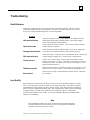
Troubleshooting................................................................................................................ 6-5
Quick Reference......................................................................................................... 6-5
Unit does not boot up..........................................................................................6-5
Cycle will not start..............................................................................................6-5
Carriages stop mid-cycle ....................................................................................6-5
Unit resets mid-cycle ..........................................................................................6-5
Curves incorrect..................................................................................................6-5
Thickness incorrect.............................................................................................6-5
Axis incorrect .....................................................................................................6-5
Lens Quality ............................................................................................................... 6-5
Unfined or gray areas toward the outside edge of the lens .................................6-6
Unfined or gray areas at the center of the lens....................................................6-6
Unfined area resembling an hour glass or off axis condition..............................6-6
Hump or depression at or near the center of the lens..........................................6-6
Excessive chatter ................................................................................................6-6
Center thickness is inconsistent ..........................................................................6-6
Prism direction incorrect.....................................................................................6-7
Prism amount incorrect.......................................................................................6-7
Job Entry Screen ........................................................................................................ 6-8
Screen entries are barely visible .........................................................................6-8
“Invalid Value” message appears at the bottom of screen ..................................6-8
Cross Curve ........................................................................................................6-8
Center Thickness ................................................................................................6-8
Edge Thickness...................................................................................................6-8
Cycle Irregularities..................................................................................................... 6-9
Job entry data is accepted, however, cycle won't start........................................6-9
Collet appears to stutter or stall during the cutting cycle....................................6-9
Cycle times too long ...........................................................................................6-9
Carriages move into cutting position, however neither cutter motor nor vacuum
operate......................................................................................................................6-10
Mercury Relay not functioning.........................................................................6-10
Cutter Motor............................................................................................................. 6-11
Motor does not run............................................................................................6-11
Motor is Noisy ..................................................................................................6-11
Processor Initialization Failure (Start Up Failure) ................................................... 6-12
Blown 20 Volt Power Supply Fuse...................................................................6-12
Home Switch Malfunction................................................................................6-12
Servo Motor Encoder Malfunction ...................................................................6-13
Blown 5 Volt Fuse ............................................................................................6-13
Encoder and Home Switch Diagnostics ................................................................... 6-13
Servo Motor Malfunction .................................................................................6-14
Checking and Adjusting Voltages............................................................................ 6-14
viii
2G User’s Manual–June 23, 2005
Contents
Preparation........................................................................................................6-15
Checking and Adjusting the 5 Volt DC Processor Voltage ..............................6-15
Checking and Adjusting the 20 Volt DC Processor Voltage ............................6-15
Checking the Power Supply Input Voltages .....................................................6-15
Transformer Supply Voltage ............................................................................6-16
24 Volt AC 4 AMP, Output ..............................................................................6-16
8 Volt AC, Output.............................................................................................6-16
24 Volt AC, 0.2 AMP Output ...........................................................................6-16
Parts Replacement .......................................................................................................... 6-17
Replacing the Cutter Motor...................................................................................... 6-17
Replacing the Cutter Motor Controller .................................................................... 6-17
Replacing the Electronics Enclosure........................................................................ 6-18
Replacing a Servo Motor ......................................................................................... 6-19
Replacing the Home Switches ................................................................................. 6-19
Replacement Parts List............................................................................................. 6-20
Chip Chute........................................................................................................6-20
Case Top ...........................................................................................................6-20
Pneumatic .........................................................................................................6-21
Electrical...........................................................................................................6-21
Cutter Motor .....................................................................................................6-21
Vacuum.............................................................................................................6-21
Motion Control .................................................................................................6-21
Accessories .......................................................................................................6-22
Cutters...............................................................................................................6-22
Collet Assembly................................................................................................6-22
Appendix A
Control Panel & Monitor Descriptions ............................................................ A-1
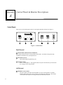
Control Panels ........................................................................................................... A-1
Right Side panel.................................................................................................A-1
Left Side panel...................................................................................................A-1
Keypad ...................................................................................................................... A-2
Monitor...................................................................................................................... A-2
Monitor Contrast Control.......................................................................................... A-3
Appendix B
Summary of Calibration Process.......................................................................B-1
Calibration Summary .................................................................................................B-1
Appendix C
Error Codes ........................................................................................................ C-1
Job Data Errors...........................................................................................................C-1
Legal Range....................................................................................................... C-1
Invalid Value ..................................................................................................... C-1
Blade will contact the block! ............................................................................. C-1
Blade will be within 0.5mm of block! Proceed with caution............................. C-1
Please verify and correct.................................................................................... C-1
Communication Errors ...............................................................................................C-2
LAN Hardware Failure ...................................................................................... C-2
Duplicate LAN ID ............................................................................................. C-2
LAN Receive Error............................................................................................ C-2
Contents
ix
Contents
LAN Transmit Timeout ..................................................................................... C-2
LAN Receive Timeout....................................................................................... C-2
Appendix D
Specialty Lenses.................................................................................................. D-1
Bi-Concave Lenses.................................................................................................... D-1
Lenticular .................................................................................................................. D-1
Myodisc..................................................................................................................... D-3
Off-Center Blocking.................................................................................................. D-3
Progressive ................................................................................................................ D-3
Saddle Back............................................................................................................... D-3
Appendix E
x
Warranty..............................................................................................................E-1
2G User’s Manual–June 23, 2005
Chapter
Before You Begin
1
Before You Begin
The 2G is a state-of-the-art 3-axis toric generator manufactured by National Optronics, Inc. It will
process Polycarbonate, Hi-index and CR-39 lenses with exceptional accuracy. A unique cutting
tool is used to dry cut the back of plastic prescription lenses with no elliptical error. The removed
material is drawn into a vacuum unit, allowing lenses to be generated without liquid coolant. Its
fully automatic cutting operation can generate base and cross curves from +30 to -30 diopters in a
nominal 45 to 90 second cutting cycle time. Prism power and direction are also computer
executed, eliminating the need for prism blocking or prism rings. Collet adapters are available for
all standard surface blocking systems.
For Further Assistance
If you should require any further assistance, National Optronics can be contacted directly between
8:30 AM and 5:00 PM ET Monday through Friday.
National Optronics
100 Avon Street
P.O. Box 1547
Charlottesville, Virginia 22902
Toll-free:(800) 247-9796
Tel:(434) 295-9126
Fax:(434) 295-7799
Parts Order Fax:(888) 239-0778
To Order Parts:
Please call our Customer Service Department at 800-247-9796 ext. 317.
Please know your part number, serial number of the machine and Customer Account Number.
If you do not know the part number of the part you need to order you will need to talk with
Technical Assistance. The following guidelines for Technical Assistance will apply in that
circumstance.
If you need to return a part, the Customer Service Department will issue a Return Authorization
Number to you and explain the procedure for returning parts.
1-1
1
For Technical Assistance:
Please call our Technical Service Department at 800-247-9796 ext. 314 and know the serial number
of your machine and Customer Account Number. If you purchased your equipment from National
Optronics, there is no charge for telephone support. If, however, you purchased your Optronics
equipment elsewhere, you will be charged for telephone support at the rate of $47.50 per half hour.
If you would like to schedule an on-site Technical Service visit, please call Technical Support at
800-247-9796 ext. 314. Please know the serial number of your machine and Customer Account
Number for requesting a Technical Service visit. There is no charge for warranty service visits. If
your machine is out of warranty, there is a charge of $55.00 per hour for travel to and from the
equipment location and $125.00 per hour (two-hour minimum) for the Technician’s time at the
location. Any additional travel expenses incurred, such as airline tickets, hotel rooms, etc., are
billed to the customer.
The rates published above may be subject to change without notice.
Requirements for Use
115 VAC 60 Hz 20A Electrical Supply
This is standard outlet power in the United States. The Optronics 2G generator should be on a
dedicated circuit (no other electrical loads connected to the same circuit) to ensure a uniform,
consistent power supply. The maximum continuous power consumption of the generator, including
the vacuum, is 14.3 amps. The 2G must be properly grounded—do not use any adapter that will
bypass the grounding plug.
Power fluctuations can adversely affect production and machine integrity. Please contact the factory
if you have power glitches or questions about the power requirements.
Note
The 2G is available for 230V 50 Hz installations. It is also recommended for 230V
units to be installed on a dedicated circuit.
Operating Conditions
The 2G is designed for indoor use only. The 2G is designed to operate safely at a temperature range
of 5° C to 40° C, at altitudes up to 2000 meters.
1-2
The 2G Generator User's Manual – June 23, 2005
1
General Specifications
Dimensions
Height: 19” (48cm)
Width: 30” (64cm)
Depth: 25” (64cm)
Weight: 110lbs. (50Kg)
Cutters
Carbide endmill. Two-fluted diamond.
Cutter Motor
20,000 RPM DC Brushless, ¾ Hp.
Vacuum
2.5 HP, 109 CFM (9A).
Lens Materials
CR-39, Polycarbonate, All High Index, Trivex, NO GLASS.
Certifications
Conforms to UL Std 61010-1
Conforms to EN 61010-1 (Model 60124 only)
Statement Against Misuse
The 2G generator is designed to edge plastic lenses only. Any other use of the machine will
compromise its safety protection features.
Caution
The 2G will edge ONLY PLASTIC LENSES. Under no circumstances should
any attempt be made to process a glass lens on this unit!
Chapter 1 Before You Begin
1-3
1
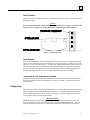
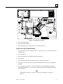
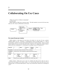
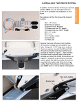
Installation Procedures
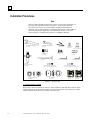
Note
These procedures should be followed in sequence, as the proper completion of a
given step may depend on the one previous to it. Tools are provided in the
accessory kit (See Figure 1) to aid in both the installation and subsequent
operation. The 2G Toric Generator is optionally shipped with a cabinet which is
custom designed for the application. The laboratory can either: (1) Use the
custom cabinet, or (2) Mount the generator on a standard workbench.
ARMATURE WRENCH 11/16"
P.N. 87495
COLLET WRENCH 24mm
P.N. 87490
QUICKDISCONNECT
P.N. 74262
CALIBRATION PLUG
P.N. 87248
15 AMP. FUSE
P.N. 77320
3/16" "L" ALLEN WRENCH
BALL END MILL, 3/8" SHAFT
P.N. 93743 - NEWER UNITS ONLY
LAP HOLDER
P.N. 2108
3.0 AMP. FUSE
P.N. 77318
(P.N. 77317 FOR 230V)
2.5 AMP. FUSE
P.N. 77324
HEX KEY SET
P.N. 87178
3/16" HEX T-HANDLE
P.N. 87452
FILTER/
REGULATOR ASS'Y
P.N. 90745
AIR GUN
P.N. 87260
(T-10) TORX WRENCH
BALL END MILL, 3/8" SHAFT
P.N. 93741 - OLDER UNITS ONLY
SYSTEM DISK
P.N. 3311
BACKUP DISK
P.N. 3306
Figure 1 - Accessory Kit
1 - Custom Cabinet Assembly
Remove the cabinet and cabinet top from box. Place cabinet top white side down on floor. Place
cabinet upside down on cabinet top with doors on same side as cutout in the cabinet top. Attach
cabinet to cabinet top with screws provided. Proceed to Step 3.
1-4
The 2G Generator User's Manual – June 23, 2005
1
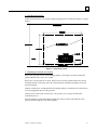
2 - Work Bench Preparation
Prepare the bench surface to be used by cutting an opening for the vacuum hose and power cord per
Figure 2.
Figure 2 - Work Bench Cutout
3 - Unpacking the Generator and Vacuum
Remove the generator from its wooden shipping pallet by removing the two bolts found on the
pallet's underside with a 13/16” box wrench.
Remove the vacuum unit from its carton. Remove the accessories from the inside of the canister
and install the large vacuum bag. Place the vacuum under the workbench, aligning its inlet with
the bench opening.
Feed the vacuum power cord through the bench opening and lay it towards the rear of the bench, as
it will be plugged into the rear of the generator.
Turn the power switch on the vacuum to the “ON” position, as its cycling is automatically
controlled by the 2G.
Place the generator on the bench/cabinet, aligning the vacuum coupler on the underside of the
generator with the right side of the bench opening.
Chapter 1 Before You Begin
1-5
1
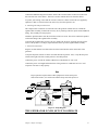
4 - Removal of Shipping Bolts
C
M UT
L O TE
20 AB TO R
1 0 EL R
0
The cutter motor carriage and the lens drive carriage are secured for shipping. To release the lens
drive carriage, remove the shipping bracket that is bolted to the base and the carriage plate. To
release the cutter motor carriage, remove the bolt in the block on the right side of the carriage.
After removing the bolt, remove the spacer between the block and cutter motor carriage. Leave the
block in place, as it acts as a carriage stop during operation. (See Figure 3).
REMOVE
SHIPPING BOLT
AND SPACER
TO OPERATE
REMOVE
SHIPPING
BRACKET
TO OPERATE
Figure 3 - Shipping Bolts
Warning
Attempting to operate the machine without removing the shipping bolts
could cause significant damage.
5 - Attaching the Vacuum System
Insert the end of the 2½" flex vacuum hose into the coupler on the bottom of the generator from
below the bench. This connects the hose to the chip chute.
Maintaining a gentle curve between the chip chute and vacuum, connect the other end of the 2½"
hose to the vacuum inlet. Note: The vacuum inlet is the lower hole in the vacuum canister. The
2½" hose should be cut to the shortest length possible with a utility knife. The shorter the hose, the
more effective the suction. The excess hose can be used to direct the heated exhaust of the vacuum
away from the machine.
1-6
The 2G Generator User's Manual – June 23, 2005
1
Connect the additional large hose from the outlet of the vacuum canister to the boot on the lower
left side of the rear of the cabinet. This hose is used to exhaust the hot air from the cabinet.
To protect your hearing, ensure that the vacuum is either in a cabinet such as the one supplied by
Optronics or that it is located at least one meter away from the operator’s ears.
6 - Attaching the Compressed Air Line
The compressed air connection is on the left side of the generator towards the rear. Install the
regulator/filter assembly, found in the accessory kit, by inserting it into the quick-connect bulkhead
fitting. The assembly will snap in place.
Attach the quick disconnect onto the end of the air line to be used. The air line can then be pushed
on the male fitting of the regulator/filter assembly.
Verify that the regulated line pressure is 80 psi, which is the necessary operating pressure for the
collet. If the pressure is not 80 psi, adjust the knob on the top of the regulator/filter assembly.
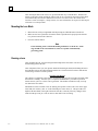
7 - Electrical Connections
Plug the vacuum cord that was laid on the rear of the bench into the socket on the back of the
generator.
Verify that all panel switches are in the out rather than the in position. Also, verify that the power
switch on the right side of the control panel is in the OFF position.
Connect the power cord for the cabinet exhaust fan to a dedicated 115 VAC wall.
Connect the power cord supplied from the back of the generator to a dedicated 115 VAC wall
receptacle of at least 15 amp capacity.
Note
Proper operation requires that no other equipment be on the same power
feed/circuit breaker, as it could cause nuisance drop-outs of the processor.
Figure 4 - Setup Diagram
THE GENERATOR IS NOW SET-UP TO OPERATE
Chapter 1 Before You Begin
1-7
1
2G Boot-Up Sequence
During the boot-up process, the 2G will perform a series of self-diagnostic tests that can prove
valuable in troubleshooting problems. The following steps are performed during boot-up.
First, the 2G will sound a series of 4 beeps, and then two short beeps. If the 2G continuously
sounds a short beep, it indicates a problem in the Electronics Enclosure. This problem has many
possible causes, including low voltage. Contact the factory for further assistance in diagnosing this
problem.
The 2G will display a series of short messages indicating a normal boot-up process; for example, it
will display, “Loading Setup Values,” “Loading Statistics,” “Loading Menus,” and “Install Serial
Ports.”
Next, the 2G will check for internal LAN communications, which requires optional specialized
hardware. It will set the LAN ID as specified in the Communications Screen. The message
“Network LAN ID: XX” will appear on the bottom line of the display, where XX is the LAN ID.
The type of ARCNet card will also be identified. If there is no ARCNet card in your 2G (or if the
ARCNet card is nonfunctional), the 2G will display the words, “No ARCNet Card found. Unable
to Initialize ARCNet.”
After the 2G checks for a network and installs Servo software, it will give the option of
immediately going to the Diagnostics Screen. The message “Press any key for Immediate
Diagnostics” will appear at the bottom of the screen. If the 2G will not complete its boot-up due to
a problem, press any key at this time to enter the Diagnostics Screen.
The First Time After a Black Box Is Installed
All of the above occurs plus the following: A message “Remove lens if present and press
READY.” will appear. After removing a lens, if present, from the chuck, press the READY key.
The 2G now will display the message “Discovering Limits,” and move its carriages to determine its
full range of motion. First, the radius carriage will come forward, and the depth carriage will move
to the left.
Caution
It is very important that no lens is present in the chuck when the 2G is
discovering its limit. If a lens is present, it could cause permanent damage to
the cutter.
The carriages will then move to home and the Job Screen will be displayed
signaling that power-up is complete.
It is also very important not to drop the 2G as it is not built to withstand
dropping.
1-8
The 2G Generator User's Manual – June 23, 2005
Chapter
Entering a Job
2
Process Overview
The steps in generating a lens are as follows:
1.
Enter a job.
2.
Generate a lens (covered in Chapter 3).
3.
Cut a matching lap for polishing if you do not have one (covered in Chapter 3).
There are two ways of entering a job: (1) from a host computer or Optronics server described on
this page, or (2) by entering data directly into the fields on the Job Screen (described on the
following page). The process is slightly different depending on which approach you are using.
Entering a Job
The 2G is designed to provide easy job data entry for lens generation.
Entering a Job from a Host Computer/Server
1.
Type in the number or use the barcode reader to enter a number into the Job Number field.
2.
Verify the information on the screen. Pay close attention to the Block Diameter field. An
incorrect Block Diameter could lead to a situation where the cutter crashes into the
block, which might ruin the cutter blade. This parameter refers to the physical diameter
of the block, not the Sag diameter.
3.
Press the READY key to orient the collet, so that you can mount the lens.
4.
Properly mount the lens. (Refer to the “Mounting the Lens Blank” section of Chapter 3,
“Generating a Lens,” for directions on mounting the lens.)
5.
Close the 2G’s lid.
6.
Press the Start button.
7.
After removing the lens, move the cursor down to the Cut Matching Lap field and press Ready
key to begin the process of cutting a lap. (Refer to the “Lap Cutting” section of Chapter 3,
“Generating a Lens,” for information about this part of the process.)
2-1
2
Entering a Job Direct (without a Host Computer/Server)
1.
Enter data for each field—refer to Job Screen field descriptions that follow. Pay close
attention to the Block Diameter field. An incorrect Block Diameter could lead to a
situation where the cutter crashes into the block, which might ruin the cutter blade. This
parameter refers to the physical diameter of the block, not the Sag diameter.
2.
Press the READY key to orient the collet, so that you can mount the lens.
3.
Properly mount the lens. (Refer to the “Mounting the Lens Blank” section of Chapter 3,
“Generating a Lens,” for directions on mounting the lens.)
4.
Close the 2G’s lid.
5.
Press the Start button.
6.
After removing the lens, move the cursor down to the Cut Matching Lap field and press Ready
key to begin the process of cutting a lap. (Refer to the “Lap Cutting” section of Chapter 3,
“Generating a Test Lens,” for information about this part of the process.)
Job Screen
Input of data on the Job Screen is required for each lens to be generated. The Job Screen will
display two jobs. The job on the right-hand side is either the one currently being generated or the
job that has just finished. The job on the left-hand side is the next lens to be run. The data for the
next job can be entered while the machine is running. A representation of the Job Screen is shown
below:
2-2
The 2G Generator User's Manual – June 23, 2005
2
The data is shown line-by-line as entered. The following is a description of each entry.
Job Number
This field is used in installations where the job entry data is entered at a remote location. By typing
in the Job Number (or Tray #), and pressing down arrow <↓> or the READY key, the complete job
entry data is automatically downloaded to the generator.
Caution
After pulling down a job from a server or host computer, verify all entries
before pressing the Ready key. Pay close attention to the Block Diameter
field—using the wrong block diameter could ruin your blade!
*HELPFUL HINT*
Should the next lens to be generated be similar to the one running, the operator can move the cursor
to the upper-most field (Job Number), and enter “0” as the job number. When the cursor is moved
down (↓) to store the entry, or the READY key is pressed, the data fields on the right side will
automatically be duplicated on the left. Then, only the fields that need to be changed must be reentered.
Barcode Reader Users
The 2G will interface with most barcode readers to provide fast job data entry into the Job Screen.
Contact the factory for interface specifications and compatible product recommendations.
The first 4 data fields relate to the base curve, cross curve, center thickness, and crib diameter of
the finished lens.
Base Curve
Enter the desired base curve in diopters. The entry must be between +6.00 and -30.00 diopters.
This field requires the entry of two decimal place values. For example, to enter a curve of 6.125,
enter the sequence 6, 1, 2, or to enter a curve of 6.00, enter the sequence 6, 0, 0. See the note below
on how this number is rounded.
Note
This value will be rounded to the either nearest eighth of a diopter (ex: 0.125,
0.250, …), or the nearest sixteenth of a diopter (ex: 0.0625, 0.1875, …). If a
value is entered in tenths (ex: 0.10, 0.20, …), the value will be left as entered.
Since only two decimal places may be entered, to enter 6.1875, enter the
sequence 6, 1, 8. To enter a diopter value of 6.20, enter the sequence 6, 2, 0.
Cross Curve
Enter the desired cross curve in diopters. The entry must be between +6.00 and -30.00 diopters,
and must have greater curvature than the base curve. For more information, refer to the “Saddle
Back Lenses” section of Appendix D, “Specialty Lenses.” The above note on rounding will also
apply to the cross curve.
Chapter 2 Entering a Job
2-3
2
Center Thickness
Enter the final center thickness, before fining and polishing, in millimeters. One decimal place
value must be entered in this field. For example, to enter a center thickness of 2.5, enter the
sequence 2, 5, or to enter 2.0, enter 2, 0.
Crib Diameter
Enter the desired crib diameter in millimeters. A value of “0” in this field will set crib diameter to
“Off.” Valid crib diameters are whole numbers between +50 and +80 mm. If this value is smaller
than the Block Diameter (Page 6), the 2G will automatically crib the lens 2 mm larger than the
Block Diameter.
The next 4 data fields specify information about the prism to be generated. The 2G’s software
automatically programs the cutter to generate prism, eliminating the need for prism rings or
blocking.
Note
Center blocking is the recommended blocking method for the 2G. Care
must be taken when using any other method of blocking. Prism is always
entered as actual rather than compensated, as no compensation is necessary
due to the accuracy of the 2G’s cutting action.
Pin Bevel:
This value will toggle between “Off” and “On” and tells the 2G if it should place a bevel on the
lens (to reduce the possibility of cutting your fingers when handling the lens, and to increase
coolant flow between the lens and the lap during fining).
Layout Axis
Enter the axis from the seg line to the cylinder line in degrees. Depending on lab convention, this
may be referred to as cylinder axis.
Prism
Enter the actual (uncompensated) prism power in diopters. This field will require entry of three
decimal place values. For example, to enter a prism amount of 2.000 prism diopters, the sequence
2, 0, 0, 0 must be entered, or to enter 1.750 diopters, the sequence 1, 7, 5, 0 must be entered. The
amount of prism must be between +0.00 and +20.00 prism diopters. This value will be rounded
using the same method explained above, under the description of Base Curve.
Prism Axis
Enter the orientation of the prism power in degrees, referenced from the layout (0-180) axis.
2-4
The 2G Generator User's Manual – June 23, 2005
2
Prism Direction
This is used in conjunction with the prism axis to determine the direction of prism. This parameter
is used for labs using a 0-180 degree, up and down notation. Labs using a 0-360 degree notation
will always leave this parameter “UP.”
The next 5 data fields describe the physical characteristics of the lens blank being used. These
parameters allow the machine to calculate the number of passes required for efficient material
removal and the distance the cutter should sweep in order to completely cover the lens face.
Front Curve
Enter the blank’s true front curve in diopters. Two decimal place values are required in this field.
For example, to enter a front curve of 6.12 diopters, enter the sequence 6, 1, 2. The front curve
must be between -30.00 and +30.00 diopters. This value will NOT be rounded. It is very
important that this number be accurate, since any error will cause an error in the center thickness.
Back Curve
Enter the back curve in diopters. In this field, two decimal places are required. For example, to
enter a back curve of 6.25, enter the sequence 6, 2, 5. The back curve must be between -30.00 and
+30.00 diopters. This value will NOT be rounded.
Edge Thickness
Enter the initial blank edge thickness in millimeters. Only whole number values are accepted. This
value must be between +1 and +30 mm.
Note
This is NOT the final edge thickness that might be indicated on the lab ticket.
Diameter
Enter the blank diameter in millimeters. A whole number value between +25 and +99 must be
entered in this field. If cribbing is desired, the maximum value for this field is 81 mm, due to the
physical characteristics of the 2G, and the cutting tool.
Material
Select the material type. This selection determines the axis speed, spiral separation and index from
the Lens Material Screen (refer to parameters). The field will automatically default to the same
material as the previous job. To change the material, press the <+/-> key. The unit is initially
configured with three lens materials: CR-39, POLY and HI-IDX (High-Index). Depending on lab
preference, you can add up to seven additional materials (see Lens Material Screen section of
Chapter 4).
Chapter 2 Entering a Job
2-5
2
Block Diameter
This is the outside diameter of the lens block. The valid range is +40 to +99 mm, and must be a
whole number. The default value is +50 mm. This number is used to determine if a cutter crash
will occur.
Note
The software is programmed to handle unreasonable data entry to prevent
the cutter from cutting into the block! This protection can be overridden,
but a warning will be given to the operator. The protection parameters
depend on the accuracy of the Block Diameter settings and the center
thickness calibration, discussed above.
Cut Matching Lap
Press the READY key to take you to the Lap Screen. Refer to the “Lap Screen” section of
Chapter 3, “Generating a Lens,” for field definitions.
2-6
The 2G Generator User's Manual – June 23, 2005
Chapter
Generating a Lens
3
Process Overview
The steps in generating a lens are as follows:
1.
Enter a job (covered in Chapter 2).
2.
Generate a lens.
3.
Cut a matching lap for polishing if you do not have one.
Generating a Lens
Blocking
Center blocking is the recommend blocking method for use in the 2G. Prism rings should not be
used with the 2G, since it is capable of automatically generating prism.
Setup Screen
During final testing at the factory the 2G was fully calibrated with machine specific entries. Unless
the parameters must be changed, the operator need only work with the Job Screen to begin
generating lenses. If changes are necessary, see instructions in the Setup Screen section.
Job Input
You must enter job data on the Job Screen as the initial step. (Refer to Chapter 2, “Entering a Job,”
if you need to review that part of the process or for an explanation of each field.) After entering the
data, move the cursor to the next field by pressing the up arrow <↑> key or down arrow <↓> key,
which will automatically store the data in the previous field. If the data is out of the allowable
range, an “Invalid Value” message will be displayed at the bottom of the screen.
3-1
3
After entering the data on the Job Screen, press the READY key to load the data. The data will
transfer to the right column, and the job will be ready to run. If prism has been entered, the chuck
will automatically orient itself as defined in Prism Arrow Location (refer to the “Prism Arrow
Location” section of Chapter 4, “Setup Screens,” for more information): If no prism is entered, pins
will rotate to a vertical position.
Mounting the Lens Blank
1.
Mount the lens with your right hand while depressing the CHUCK button with the left.
2.
Make sure the lens is pushed as far into the chuck as possible and is properly located on the
two pins and seated on the collet face.
3.
Press the CHUCK button.
Note
Center blocking is the recommend blocking method for use in the 2G. Prism
rings should not be used with the 2G, since it is capable of automatically
generating prism.
Running a Lens
After mounting the lens, close the Plexiglas lid and depress the start button. The 2G will
automatically generate the lens.
After completion of the cycle, the operator should lift the Plexiglas shield, and holding the lens in
the right hand, release the CHUCK button with the left. The chuck will not release until the lens
collet carriage returns to its home position.
*NOTES AND HINTS*
The software is configured so the operator can input the next job to be run in the left column while
the machine is running. After the cycle is completed, the READY key can then be pressed to
transfer the new job over, so that it can be generated. The machine will then be ready to accept
new data in the left column.
Should the next lens be similar to the one running, the operator can move the cursor to the upper
most field (Job Number), enter “0” in the field and press arrow down (↓). This procedure will
duplicate the data fields of the right side into the left side, so that any necessary changes can be
made from the previous job. This can also be done while a lens is running.
3-2
The 2G Generator User's Manual – June 23, 2005
3
Lap Cutting
Process Overview
1.
Fill in data on the Lap Screen.
2.
Press the Ready key to position the collet preparatory to loading the lap.
3.
Place the lap into the lap holder, and tighten the bolt with a small amount of pressure.
Overtightening can cause the lap to deform, producing inaccurate curves.
4.
Load the lap into the Chuck.
5.
Press the CHUCK button to grip the lap holder.
6.
Press the START button to begin cutting the lap.
Lap Screen
Enter the Lap Screen from the Job Screen by pressing the READY key from the Cut Matching Lap
field. See the figure shown below for the layout of the Lap Screen.
Lap Material Screen
Press SET-UP to exit
Finish..
Sep
FR
other
1.00 60
Coburn 1.00 60
DAC
1.00 60
OWC
1.00 60
PSI
1.00 60
Salem
1.00 60
GCFoam 1.25 150
PSISnap 1.25 150
Rough...
Sep FR TO
1.20 100 6
1.20 100 6
1.20 100 6
1.20 100 6
1.20 100 6
1.20 100 6
2.50 200 17
2.50 200 17
Sep = Spiral Sep
FR = Feed Rate
TO = Pass Takeoff
PT SC Tool
0.46 Y 1.530
0.46 Y 1.530
0.46 Y 1.530
0.46 Y 1.530
0.46 Y 1.530
0.46 Y 1.530
0.46 N 1.530
0.46 N 1.530
PT = Pad Thickness
SC = Skim Cut
Tool = Tool Index
The following is a description of the fields used when cutting a lap.
Base Curve
Enter the base curve of the lap to be generated. The allowable range for this value is between
-6.000 and +30.000. See the following note.
Chapter 3 Generating a Lens
3-3
3
Note
The 2G expects a base and cross curve value of three (3) decimal places, and will
not round off any entered values. For example, to enter a base curve of 6.500,
enter the series 6, 5, 0, 0.
Cross Curve
Enter the cross curve of the lap to be generates. The allowable range for the cross curve is -6.000
to +30.000. See note above on rounding.
Pad Thickness
If laps are used that are compensated, enter the amount of compensation in mm. The allowable
range for the pad thickness is between 0.00 and +3.00 mm. Two decimal place values are required
in this field. The following chart shows some common pad compensation values.
Inches
0.018
0.022
0.028
0.032
Millimeters
0.45
0.55
0.70
0.80
Lap Manufacturer
Select the manufacturer for the lap you are using. Every time a lap is to be cut, the 2G will select
the chosen manufacturer’s best fit lap to cut the desired curves. The 2G will use the cutting
parameters as defined on the Lap Material Screen for that manufacturer.
Lap Type
Shows the recommended lap for the manufacturer selected in the Lap Manufacturer field. This lap
type recommended is the lap that requires the least amount of stock removal to be able to cut the
curves specified in the Base Curve and Cross Curve fields.
Blank Base Curve
Enter the existing base curve of the lap to be used in diopters. Two decimal place values are
expected in this field. For example, to enter a blank base curve of 6.25, enter the sequence 6, 2, 5.
This entry must be between -30.00 and +30.00
Blank Cross Curve
Enter the existing cross curve of the lap to be used in diopters. Two decimal place values are
required. This entry must be between -30.00 and +30.00.
Diameter
Enter the diameter of the lap in mm. A whole number value between +20 and +100 is required for
this field.
3-4
The 2G Generator User's Manual – June 23, 2005
3
Center Thickness
Enter the actual center thickness of the lap. A whole number value between +10 and +100 must be
entered in this field.
*NOTE*
It is very important that the center thickness be measured from the very base of the lap to the
top of the lap. See Figure 1 for further instructions on measuring the center thickness.
Figure 1 - Measuring a Lap
Center Removal
Enter the desired amount of removal of material from the center of the lap. Usually this number is
small, 1-2 mm. This field expects one decimal place value to be entered. For example, for a center
removal of 1.0 mm, enter the sequence 1, 0. This can be supplied automatically by the 2G software
when you enter data in the Lap Manufacturer field and either change or accept the recommended
lap type in the Lap Type field. The removal measurement here may be rounded up slightly from
the amount shown in the center removal field discussed below to prevent overcutting.
“center removal” and “edge removal” at bottom
Display-only fields that show the values calculated by the 2G software based on the manufacturer
and type specified in the in the Lap Manufacturer and Lap Type fields. Center removal is always
1.0 mm or more.
Cutting a Lap
When the required data is entered, press the READY key to load the data. Place the lap into the lap
holder, and tighten the bolt with a small amount of pressure. Overtightening can cause the lap to
deform, producing inaccurate curves. At this point, the lap is ready to be mounted inside the 2G.
To start cutting the lap, press the START button.
*HELPFUL HINT*
Should the next lap to be cut be similar to the one currently running, the operator can move the
cursor to the Repeat Last Lap line on the top of the screen, and press the READY key. This will
recall the data from the previous job, so that only the fields to be changed need to be reentered.
Chapter 3 Generating a Lens
3-5
Chapter
Setting Up the 2G
4
Setup Screen
Calibration of the 2G generator is accomplished through variables in the software accessed via the
unit's Setup Screen. The 2G is designed to retain all the set-up data when the power to the unit is
switched off. This allows the generator to be ready to run when turned on.
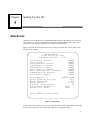
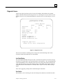
Figure 1 illustrates the layout of the Setup Screen. This is an example only; not all values will be
the same for all machines.
Setup Screen
Press SET-UP to exit
Software Version: 3.29
Calibration Screen:
Servo Screen:
Lens Material Screen:
Lap Material Screen:
Diagnostics Screen:
Servo Burn-In Screen:
Move Carriages for Cleaning:
Communications Screen:
Statistics Screen:
Block Brand:
Block Diameter for Sag:
Block Thickness:
Blade Radius:
End Mill Flute Length:
Prism Arrow Location:
Default Pin Bevel:
READY
READY
READY
READY
READY
READY
READY
READY
READY
COBURN ALUM
50.0
9.0
10.200
20
None
Last
Press READY to enter menu
Figure 1 - Setup Screen
To access this screen from the Job Screen, press the SET-UP key on the keypad. Please ensure that
all Setup Screen entries are correct before proceeding to any subsequent screens.
4-1
4
The first section of the Setup Screen provide access to additional screens. To access any of these
additional screens, move the cursor (using <↑> or <↓>) to the line which denotes the screen you
want to access, and press the READY key. The flowchart on the following page is provided for
easy reference and clarification of the various screens. The second section of the Setup Screen
contains data pertinent to the proper operation and calibration of the 2G. Once set, changes to this
section should rarely, if ever, need to be made.
Setup Screen Field Descriptions
Block Brand
Select the type of blocking system being used. To change the value in this field, press the +/- key
to scroll through the list of common block types. Any changes to this value may also change the
Block Diameter for Sag and Block Thickness values.
Block Diameter for Sag
This is the diameter in mm of the surface blocks or blocking ring being used. This information is
only used in calculating center thickness. The accuracy or this value is critical for obtaining
accurate center thickness. The allowable range of this parameter is +25 to +75 mm. The factory
default value is +50 mm. The follow table shows common Block Diameter for Sag values.
Brand
Coburn
PSI
Optek
Others
Block Diameter for Sag
50
50
58 (may vary)
Contact Factory
Blade Radius
This is the blade radius of the tool being used. It is changed only during calibration if a different
size cutting tool is installed. For the ½” diameter carbide cutting tool the setting is +6.350 mm. For
diamond cutters, refer to the accompanying tag (usually, this value will be around +10.000 mm).
End Mill Flute Length
This is the length of the cutting surface on the cutting tool. For the standard ½" diameter carbide
endmill cutter the setting is 26 mm (for a 6-fluted carbide ball 17 mm), and an extended flute
diamond cutter is 22 mm. If in doubt, measure the flute length from the tip to the very back of the
cutting flute.
Prism Arrow Location
By individual lab preference, either the apex or the base direction of the prism arrow is marked
during surface layout. This entry allows a lab to configure the generator to its particular
convention. Utilizing this parameter, the generator will automatically orient the collet for the labs
method of marking prism. Three choices are valid in this field: “Base”, “Apex”, and “None”.
With “Base”, the prism base will always be up. With “Apex” selected, the prism apex will always
be up. With “None” selected, the bifocal will always be down, which eliminates the need to mark
lenses.
4-2
The 2G Generator User's Manual – June 23, 2005
4
Default Pin Bevel
This sets the Pin Bevel field on the Job Screen default to On, Off or the same as the value for the
last job. The default can be overridden by a host computer or the operator.
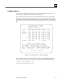
Screen Flowchart
Refer to the screen flowchart on the following page for an overview of the different patterns of
screen access when using the 2G software.
Lap Screen
Press SET-UP to exit
Job Screen
Job Number:
Base Curve:
Cross Curve:
Center Thickness:
Crib Diameter:
Pin Bevel:
Layout Axis:
Prism:
Prism Axis:
Prism Direction:
-
0.000
0.000
0.0
-
Off
Off
Off
Off
+
Up
+
Up
0
0.000
0
Repeat Last Lap:
0.000
0.000
0.0
0
0.000
0
Cut Matching Lap
Press READY
* Blank Data *
Front Curve:
Back Curve:
Edge Thickness:
Diameter:
Material:
Block Diameter:
Cut Matching Lap:
+
-
0.00
0.00
0
0
CR-39
50
+
-
0.00
0.00
0
0
Barcode or enter job number
Setup
+
+
0.000
0.000
0.00
+
+
0.00
0.00
0
0
0.0
2G SCREEN FLOWCHART
SOFTWARE VERSION 3.29
PSI
2B/80mm
Blank Base Curve:
Blank Cross Curve:
Diameter:
Center Thickness:
Center Removal:
+
+
2.00
2.00
79
27
3.2
Press READY to Load Data
center removal:
edge removal:
3.19
1.00
Password
Calibration Screen:
Servo Screen:
Lens Material Screen:
Lap Material Screen:
Diagnostics Screen:
Servo Burn-In Screen:
Move Carriages for Cleaning:
Communications Screen:
Statistics Screen:
Block Brand:
Block Diameter for Sag:
Block Thickness:
Blade Radius:
End Mill Flute Length:
Prism Arrow Location:
Default Pin Bevel:
READY
READY
READY
READY
READY
READY
READY
READY
READY
COBURN ALUM
50.0
9.0
10.200
20
None
Last
Calibrate
Calibrate
Calibrate
Calibrate
Calibration Screen
Press SET-UP to exit
Axis:
Thickness:
Lens Curve:
Lens Curve (Carbide):
Axis Bias:
Thickness Bias:
Lens Curve Bias:
Lap Curve Bias:
Lap Holder Thickness:
*Lenses*
-6.00D Correction:
-1.00D Correction:
-12.00D Correction:
+
+
+
0.000
0.000
0.000
*Laps*
+6.00D Correction:
+1.00D Correction:
+12.00D Correction:
+
+
+
0.000
0.000
0.000
Servo Screen
Press SET-UP to exit
Find Carriage Limits:
Find Servo Backlash:
READY
READY
0
0
0
CR-39
POLY
Hi-Idx
Trivex
$FINAL
$ in
# in
& in
Sep
Feed
Press READY to enter menu
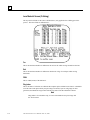
Lens Material Screen
Press SET-UP to exit
Finish.. Rough...
Sep Feed Sep Feed TO RPM
1.00 100 2.00 100 10 80.0
0.63 60 1.00 80 7 80.0
1.00 60 1.00 60 9 80.0
0.63 60 1.00 80 7 80.0
1.00 60 1.00 60 9 80.0
1.00 60 1.00 60 9 80.0
1.00 60 1.00 60 9 80.0
1.00 60 1.00 60 9 80.0
1.00 60 1.00 60 9 80.0
1.00 60 1.00 60 9 80.0
1.00 60
1 80.0
Time Elapsed: 0:00:00 of 4:00:00
Depth Velocity: 20.0 mm/sec
Axis Velocity:
25.0 rev/min
Radius Velocity: 20.0 mm/sec
AXIS
+
No
Start Switch:
Start Lamp:
Emergency Loop:
0.000 mm
0.000 deg
0.000 mm
0
DEPTH
+
0
No
RADIUS
+
0
No
Off
Off
No
Keypad:
Serial Loopback1: ?
Serial Loopback2: >
Arcnet Connected: Yes
Depth
**Special Options**
Press 09 for Servo Diagnostics
Communications Screen
Press SET-UP to exit
* Comm Settings *
Arcnet Connection:
None
Com1 Connection:
Com1 Baud Rate:
Com1 Protocol:
Host
9600
OMA
Com2 Connection:
Com2 Baud Rate:
Barcode
300
* Comm Software *
Manage Code:
Save Setup to Floppy:
Restore Setup from Floppy:
READY
READY
READY
Statistics Screen
Press SET-UP to exit
*Cycle Stats*
avg avg
% of
Count Pass Time Total PB Crib
CR-39
0 0.0 0:00
0
0%
0%
POLY
0 0.0 0:00
0
0%
0%
HI-IDX
0 0.0 0:00
0
0%
0%
LAP
0 0.0 0:00
0
Total
0 0.0 0:00
0%
0%
Reset Cycle Data:
RESET
*Maintenance Counters*
# Cycles # Passes
Vac Bags
0
0
RESET
Blades
0
0
RESET
Motor
0
0
RESET
*Other Counters*
Interrupt Events
0
RESET
Axis Depth Radius
Home Fail
0
0
0
RESET
Servo Fail
0
0
0
RESET
Press READY to reset data
Chapter 4 Setting Up the 2G
0.00
0.00
0
0
CR-39
50
Press READY for next step
Press SETUP for next exit
Enter Blank Front in Diopters
CR-39
POLY
Hi-Idx
Trivex
+/-
$ in
# in
& in
Sep
Feed
PBW =
Cribbing........
Sep Feed For Bck
2.00 150
6
4
1.00 100
4
3
1.00 60
5
5
1.00 100
4
3
1.00 60
5
5
1.00 60
5
5
1.00 60
5
5
1.00 60
5
5
1.00 60
5
5
1.00 60
5
5
PBW
0.60
1.00
1.00
1.00
1.00
1.00
1.00
1.00
1.00
1.00
Ring
1.530
1.530
1.530
1.530
1.530
1.530
1.530
1.530
1.530
1.530
Press +/- for next screen
name: Final Pass is Skim Cut
name: Gentle Entry into Lens
name: Variable Spiral Separation
= Spiral Sep
For = Forward Crib
= Feed Rate
Bck = Backward Crib
Pin Bev Width Ring = Ring Index
Lap Material Screen
Press SET-UP to exit
*Servo Motors*
Position:
Home:
+
-
Lens Material Screen
Press SET-UP to exit
Tool
1.530
1.530
1.530
1.530
1.530
1.530
1.530
1.530
1.530
1.530
Diagnostics Screen
Press SET-UP to exit
Servo Burn-In Screen
Press any key to Exit
Blank Front Curve:
Blank Back Curve:
Edge Thickness:
Blank Diameter:
Material:
Block Diameter:
READY
READY
Press +/- for next screen
name: Final Pass is Skim Cut
name: Gentle Entry into Lens
name: Variable Spiral Separation
= Spiral Sep
RPM = Max Axis RPM
= Feed Rate
Tool = Tool Index
TO = Pass Takeoff
DO NOT LEAVE COMPLETELY UNATTENDED!
Calibration Screen
Press SET-UP to exit
READY
READY
READY
READY
+
3.0
+ 120.00
+ 80.000
+ 0.000
+ 14.000
Cut Test Lens:
Cut Test Lap:
Press READY to enter menu
Press READY to enter menu
Depth Home:
Axis Home:
Radius Home:
0.000
0.000
0.00
Base curve in diopters
Setup Screen
Press SET-UP to exit
Software Version: 3.29
axis backlash:
radius backlash:
depth backlash:
+
+
*Blank Data*
Lap Manufacturer:
Lap Type:
CR-39
50
READY
READY
Base Curve:
Cross Curve:
Pad Thickness:
Finish..
Sep
FR
other
1.00 60
Coburn 1.00 60
DAC
1.00 60
OWC
1.00 60
PSI
1.00 60
Salem
1.00 60
GCFoam 1.25 150
PSISnap 1.25 150
Rough...
Sep FR TO
1.20 100 6
1.20 100 6
1.20 100 6
1.20 100 6
1.20 100 6
1.20 100 6
2.50 200 17
2.50 200 17
Sep = Spiral Sep
FR = Feed Rate
TO = Pass Takeoff
PT SC Tool
0.46 Y 1.530
0.46 Y 1.530
0.46 Y 1.530
0.46 Y 1.530
0.46 Y 1.530
0.46 Y 1.530
0.46 N 1.530
0.46 N 1.530
PT = Pad Thickness
SC = Skim Cut
Tool = Tool Index
Move Carriages for Cleaning Screen
1) Open lid, and turn cutter motor off
Vacuum position 1
2) Vacuum position 2
3) Vacuum position 3
4) Turn cutter motor on, and close lid
Press READY to Continue
4-3
4
Calibration Screen
This screen contains values for the Axis Bias, Thickness Bias, Lens Curve Bias, Lap Curve Bias,
Lens Range Correction, and Lap Range Correction. See Chapter 5, “Calibration” for more a more
detailed discussion of how to set the following values. This screen can be accessed from the Setup
Screen by moving the cursor to the Calibration Screen line and pressing the READY key.
Figure 2 illustrates the layout of the Calibration Screen, followed by an outline of each entry.
Figure 2 - Calibration Screen
Note
These are default values. Each machine will have unique values for proper
calibration, which will not necessarily match the above values.
The Cut Test Lens feature will automatically “bounce” between the Calibration
Screen and the Job Screen during the fine tuning of curves, center thickness, etc.
The Cut Test Lap feature will automatically “bounce” between the Calibration
Screen and the Lap Screen during the fine tuning of curves, center thickness, etc.
Special Note
The values on the Calibration Screen are only temporarily saved during this
procedure while the operator is fine-tuning. It is necessary to press the SETUP key once to exit the Calibration Screen and again to exit the Setup Screen
and return to the Job Screen to permanently save the calibration values.
Axis Bias
This controls the relative angular position of the rotating chuck assembly. It is used during
calibration to adjust axis position. The units are degrees. Normally, this value is between 0.0 and
+5.0. Once set at the factory, the only time that this number should change is when a new home
switch, or a collet assembly is installed.
4-4
The 2G Generator User's Manual – June 23, 2005
4
Thickness Bias
This is the distance from the initial home position of the cutter to the plunge depth of the cutter into
the lens on the final pass. The units are in millimeters. It is used during calibration to set center
thickness.
Lens Curve Bias
This is initially set using the Calibrate Lens Curve. It controls the relative position of the lens
drive table to the depth carriage. This aligns the cutter blade with the center of the lens. The units
are in millimeters.
Lap Curve Bias
This is a corrective offset to the Lens Curve Bias used to ensure true curves when cutting laps.
Lap Holder Thickness
This is the thickness of the lap holder used to ensure accurate stock removal when cutting laps.
This number will always be a positive number.
-6.00D Correction
This is used to adjust the curves for accuracy at -6.00D (the approximate mid-point for the most
commonly cut lenses).
+6.00D Correction
This is used to adjust the curves for accuracy at +6.00D (the approximate mid-point for the most
commonly cut laps).
Range Calibration
The curves can also be adjusted at ±1.00D and ±12.00D if the operator needs to compensate at
these extremes. See “Adjusting the Curves” in Chapter 5, “Calibration,” for proper calibration
techniques. The units are in millimeters.
Note
Range Calibration is optional and may not be necessary to adjust for proper
operation. Many operators will find that the -6.00D Correction and +6.00D
Correction will bring in all curves with sufficient accuracy. A negative number
will produce a steeper curve and a positive value will produce a weaker curve. If
in doubt about how to use these values or whether you need to, leave them at the
factory settings.
Chapter 4 Setting Up the 2G
4-5
4
Axis Calibration Screen
When you press the READY key while on the Calibration Axis field, you go to the Axis
Calibration Screen:
The fields are self-explanatory. For instructions on calibrating the axis, refer to Chapter 5,
“Calibration.”
4-6
The 2G Generator User's Manual – June 23, 2005
4
Lens Material Screen
This screen allows the adjustment of the cutting parameters, including Spiral Separation, Feed
Rate, Takeoff, Axis Velocity, and Tool Index for various materials.
The Lens Material Screen (see Figure 3) can be accessed from the Setup Screen by pressing the
READY key when the cursor is on the Lens Material Screen line. The parameters entered in the
fields control the speed and surface finish during the generating cycle and can be changed within
specific limits. To exit the Lens Material Screen and return to the Setup Screen, press the SET-UP
key.
CR-39
POLY
Hi-Idx
Trivex
$FINAL
$ in
# in
& in
Sep
Feed
Lens Material Screen
Press SET-UP to exit
Finish.. Rough...
Sep Feed Sep Feed TO RPM
1.00 100 2.00 100 10 80.0
0.63 60 1.00 80 7 80.0
1.00 60 1.00 60 9 80.0
0.63 60 1.00 80 7 80.0
1.00 60 1.00 60 9 80.0
1.00 60 1.00 60 9 80.0
1.00 60 1.00 60 9 80.0
1.00 60 1.00 60 9 80.0
1.00 60 1.00 60 9 80.0
1.00 60 1.00 60 9 80.0
1.00 60
1 80.0
Tool
1.530
1.530
1.530
1.530
1.530
1.530
1.530
1.530
1.530
1.530
Press +/- for next screen
name: Final Pass is Skim Cut
name: Gentle Entry into Lens
name: Variable Spiral Separation
= Spiral Sep
RPM = Max Axis RPM
= Feed Rate
Tool = Tool Index
TO = Pass Takeoff
Figure 3 - Lens Material Screen—Finish and Rough
The Lens Material Screen has two forms: the one shown above for Finish and Rough material
settings and one for Cribbing. The Cribbing form is discussed after the Finish and Rough form—
and can be accessed by pressing the +/- key.
The following is a description of each entry.
Chapter 4 Setting Up the 2G
4-7
4
Lens Material Screen (Finish and Rough)
Material
This is a description of the material being processed (that is, CR-39, POLY, etc.) and will appear in
the Material field on the Job Screen. The first two lines are reserved for CR-39 and POLY
(Polycarbonate) and cannot be erased, but can have a suffix added. The third line defaults to HiIdx (high index), the fourth to Trivex, but can be erased or modified. The remaining lines may be
customized with any names and feed rates.
To create a custom material, place the cursor in a blank material field and press the CLEAR key.
The cursor will move just to the right of the field name; press the <1> key to scroll up through
upper and lower case letters and symbols (if the desired letter or symbol is bypassed the <2> key
will scroll back down through the available characters). After the appropriate character has been
selected press the <3> key to move to the next character position. Select the next character of the
name with the <1> and <2> buttons. Press the <↑> or <↓> Arrow key to end the entry. To erase
an existing custom entry, move the cursor to the desired entry location and press the CLEAR key,
followed by the <↑> or <↓>.
If one of the following ASCII characters ($, #, or &) is anywhere in the material name, the software
will automatically add the associated feature(s). These characters can be scrolled to with the <1>
or <2> key as described above. They may even be added to the CR-39 and POLY settings: press
the CLEAR key while in one of these fields, and the cursor will jump to the end without deleting
the name. The operator may then add the custom feature.
Sep (Finish & Rough)
This parameter determines the distance between each sequential circular sweep of the tool as it
moves across the lens during the cutting pattern. The smaller the spiral separation, the smoother
the surface finish. Reducing the spiral separation, though, will increase the cycle time as the cutter
requires more time to sweep the lens. Also, the increased time that the cutter is in contact with the
lens can cause premature wear of the cutter. The boundaries of this parameter are 0.32 mm to
2.54 mm.
Feed (Finish & Rough)
This parameter controls the lens feed rate, which in turn defines the surface cutting speed of the
cutter. The larger the feed rate, the faster the cycle time. Increasing feed beyond the cutter's ability
to cleanly remove material, though, could result in an unacceptable finish. This should be set,
taking into account both surface finish and the cycle time. The boundaries of this parameter are 1
mm/sec to 200 mm/sec.
Note
The feed rate is the most important setting that affects cycle time and thus should
be maximized.
TO
This is the maximum depth of material that can be taken off (TO=Take Off) in one pass. The valid
range is 1 to 17 mm. This value, along with the End Mill Flute Length on the Setup Screen will
determine the amount of material removed in a single pass.
4-8
The 2G Generator User's Manual – June 23, 2005
4
RPM
Maximum RPM for the Axis. This is generally set to 80 rpm, but may be slowed to 60 if you
notice pitting toward the center of the lens.
Tool (Tool Index)
This is the Index of Refraction that was used as the basis for cutting the laps being used for fining
and polishing. It should be set to the lap manufacturer’s specifications and should be in agreement
with the Tool Index in the Rx calculation software.
$ - Final Pass Is Skim Cut
This feature will allow the cutter to rough cut a lens and finish up with a light, smooth pass. It is
invoked by including a dollar symbol “$” as any character in the material name on the Lens
Material Screen. When the material with the “$” symbol is chosen, all but the final pass will run at
the settings for that material. The final pass will be cut at the “$FINAL” settings. The final pass
can be used on any material and the “$” may be anywhere in the name. This can be configured for
a final pass takeoff of 1 or 2 mm under the “$FINAL” material settings.
Note
This feature will increase cycle time for those lenses that are currently being
generated with a single pass, since this feature requires a second pass.
# - Gentle Entry into Lens
This will provide an especially gentle entry in the lens at the beginning of the cut. It is useful for
thick polycarbonate or maintaining sharp knife edges. The feature is invoked by including a pound
symbol “#” as any character in the material name (POLY#, for instance).
& - Variable Spiral Separation
This option will increase Spiral Separation up to 2.50 mm at the center of the lens.
Chapter 4 Setting Up the 2G
4-9
4
Lens Material Screen (Cribbing)
The Sep and Feed fields are the same as defined above, only applied to the Cribbing part of the
process. The other fields are defined below:
For
This is the maximum number of millimeters the 2G can crib while moving forward into the lens.
Bck
This is the maximum number of millimeters that the 2G will go for each pass while moving
backwards.
PBW
This is width (in mm) of the Pin Bevel.
Ring Index
This is the index of refraction on which the Rx computer prism calculations are based. It should be
set to the same index upon which your prism rings are based (if you are using rings for other
generators) and should be in agreement with the ring index in the Rx calculation software.
Note
Ring Index is for calculation only; it is not recommended to use prism rings with
the 2G Generator.
4-10
The 2G Generator User's Manual – June 23, 2005
4
Lap Material Screen
This screen allows the adjustment of the cutting parameters, including Spiral Separation, Feed
Rate, Takeoff, Pad Thickness, Skim Cut, and Tool Index for various materials.
Lap Material Screen
Press SET-UP to exit
Finish..
Sep
FR
other
1.00 60
Coburn 1.00 60
DAC
1.00 60
OWC
1.00 60
PSI
1.00 60
Salem
1.00 60
GCFoam 1.25 150
PSISnap 1.25 150
Rough...
Sep FR TO
1.20 100 6
1.20 100 6
1.20 100 6
1.20 100 6
1.20 100 6
1.20 100 6
2.50 200 17
2.50 200 17
Sep = Spiral Sep
FR = Feed Rate
TO = Pass Takeoff
PT SC Tool
0.46 Y 1.530
0.46 Y 1.530
0.46 Y 1.530
0.46 Y 1.530
0.46 Y 1.530
0.46 Y 1.530
0.46 N 1.530
0.46 N 1.530
PT = Pad Thickness
SC = Skim Cut
Tool = Tool Index
Sep (Finish & Rough)
This parameter determines the distance between each sequential circular sweep of the tool as it
moves across the lap during the cutting pattern. The smaller the spiral separation, the smoother the
surface finish. Reducing the spiral separation, though, will increase the cycle time as the cutter
requires more time to sweep the lap. Also, the increased time that the cutter is in contact with the
lap can cause premature wear of the cutter. The boundaries of this parameter are 0.32 mm to
2.54 mm.
Feed Rate
This parameter controls the lap feed rate, which in turn defines the surface cutting speed of the
cutter. The larger the feed rate, the faster the cycle time. Increasing feed beyond the cutter's ability
to cleanly remove material, though, could result in an unacceptable finish. This should be set,
taking into account both surface finish and the cycle time. The boundaries of this parameter are 1
mm/sec to 200 mm/sec.
Note
The feed rate is the most important setting that affects cycle time and thus should
be maximized.
Chapter 4 Setting Up the 2G
4-11
4
Take Off
This is the maximum depth of material that can be taken off (TO=Take Off) in one pass. The valid
range is 1 to 17 mm. This value, along with the End Mill Flute Length on the Setup Screen will
determine the amount of material removed in a single pass.
Pad Thickness
If laps are used that are compensated, enter the amount of compensation in mm. The allowable
range for the pad thickness is between 0.00 and +3.00 mm. Two decimal place values are required
in this field. The following chart shows some common pad compensation values.
Inches
0.018
0.022
0.028
0.032
Millimeters
0.45
0.55
0.70
0.80
Skim Cut
When set to “Y” this will provide a final skim pass on all laps being surfaced ensuring the best
possible surface finish and curve accuracy.
Tool (Tool Index)
This is the Index of Refraction that was used as the basis for cutting the laps being used for fining
and polishing. It should be set to the lap manufacturer’s specifications and should be in agreement
with the Tool Index in the Rx calculation software.
4-12
The 2G Generator User's Manual – June 23, 2005
4
Diagnostic Screen
On this screen the 2G performs a series of tests to its hardware with readouts to the operator.
Figure 4 illustrates the layout of the Diagnostic Screen. The Diagnostic Screen can be accessed
from the Setup Screen by pressing the READY key when the cursor is on the Diagnostic Screen
line.
Diagnostics Screen
Press SET-UP to exit
Position:
Home:
*Servo Motors*
AXIS
DEPTH
+
0
+
0
No
No
Start Switch:
Start Lamp:
Emergency Loop:
RADIUS
+
0
No
Off
Off
No
Keypad:
Serial Loopback1: ?
Serial Loopback2: >
Arcnet Connected: Yes
**Special Options**
Press 09 for Servo Diagnostics
Figure 4 - Diagnostic Screen
This screen will initiate a continuing series of steps to check the functioning of the various
electronic controls and sensing devices in the machine.
Axis/Depth/Radius
The Axis, Depth and Radius Carriages are static. This allows the operator to move the carriages
and check for varying position, rate (speed) and home switch operation. The corresponding home
switch should indicate “YES” when the operator moves any carriage into its home position, and
“NO” when the carriage is away from its home position. The number of the counts is relatively
unimportant, but the count should move smoothly when a coupler is rotated, without any large
jumps.
These can be jogged by pressing 0 then 9 and following the instructions.
Start Switch
This should say “ON” when the green start switch is depressed, otherwise, it should read “OFF.”
Chapter 4 Setting Up the 2G
4-13
4
Start Lamp
The reading here should correlate with the start switch lamp.
Emergency Loop
This field will display the state of the Emergency loop. This will read “Yes” when the lid is down,
the Chuck is pressed and the STOP is released.
Keypad
This field will indicate the last key (or button) pressed. The number keys are indicated as numbers,
and the other key are denoted as follows:
SETUP s +/- (plus/minus)p
READY r ↑ (up arrow)u
CLEAR c ↓ (down arrow)d
Serial Loopback
The continually changing series of letters, numbers, and symbols indicates what is being sent out of
the serial ports. The serial ports can be tested by placing a jumper across pins 2 & 3 of the serial
port connection on the back of the 2G for COM1. For COM2, place a jumper across pins 1 & 14 of
the serial port connection on the back of the 2G. If the serial port is working properly, the display
should change from a single character to the same character being printed twice. For example, the
display should change from {A, B, C, …} to {AA, BB, CC, …} if the serial port is working
properly.
ARCNet Connected
This will indicated whether or not the 2G is connected to a network. If this reads “NO,” but the 2G
is physically connected to a network, it indicates a problem with the network. Possible causes are a
bad co-axial (coax) cable, or a duplicate LAN ID, or no Arcnet card present.
To exit the Diagnostic Screen, press the SET-UP key.
*IF THE UNIT WILL NOT BOOT UP*
The operator may get to this screen by pressing and holding down the any key while turning the
machine on. The machine will go directly to this screen without going through the usual boot-up
procedures.
4-14
The 2G Generator User's Manual – June 23, 2005
4
Communications Screen
Use the Communications Screen to set up communications to a host computer or a barcode scanner.
Communications Screen
Press SET-UP to exit
* Comm Settings *
Arcnet Connection:
None
Com1 Connection:
Com1 Baud Rate:
Com1 Protocol:
Host
9600
OMA
Com2 Connection:
Com2 Baud Rate:
Barcode
300
* Comm Software *
Manage Code:
Save Setup to Floppy:
Restore Setup from Floppy:
READY
READY
READY
Comm Settings:
Arcnet Connection: (Requires optional equipment) Specifies the type of Arcnet connection
(Host or None).
Arcnet Node ID:
(This field disappears when Arcnet Connection is set to None.)
Specifies the Node ID of the Arcnet connection. The value can be 1249.
Arcnet Protocol:
(This field disappears when Arcnet Connection is set to None.) NOP is
the only protocol selection.
Com1 Connection: Specifies the device connected to from the COM 1 port; choices are
Host, Barcode, or None.
Com1 Baud Rate:
Specifies the baud rate used for communications to the COM 1 device.
If the Com1 Connection field is set to None, this field will not appear.
COM1 Protocol:
Under Com1Baud Rate ONLY when Com1 Connection is “Host”—This
field only appears when Arcnet Connection is set to “None” and Com1
has a Host configured.) OMA is the only selection.
Com2 Connection:
Specifies the device connected to from the COM 2 port; choices are
Host, Barcode, or None.
Chapter 4 Setting Up the 2G
4-15
4
Com2 Baud Rate:
Specifies the baud rate used for communications to the COM 2 device.
If the Com2 Connection field is set to None, this field will not appear.
COM2 Protocol:
Under Com2 Baud Rate ONLY when Com2 Connection is “Host”—
This field only appears when Arcnet Connection is set to “None” and
Com2 has a Host configured.) OMA is the only selection.
Comm Software:
Manage Code
Allows you to load the new code from a floppy drive.
Save Setup to Floppy
Saves all calibration, setup numbers, and statistics (all data saved
across power cycles) to disk for future retrieval with the Restore
Setup from Floppy feature.
Restore Setup from Floppy Restores from floppy all the numbers saved to floppy with the
Save Setup to Floppy feature.
4-16
The 2G Generator User's Manual – June 23, 2005
4
Statistics Screen
Use the Statistics Screen to review various types of machine cycles. Also, when you change the
vacuum bag, cutter blade or motor, reset the cycles to zero counts.
Statistics Screen
Press SET-UP to exit
*Cycle Stats*
avg avg
% of
Pass Time Total PB Crib
CR-39
0 0.0 0:00
0
0%
0%
POLY
0 0.0 0:00
0
0%
0%
HI-IDX
0 0.0 0:00
0
0%
0%
LAP
0 0.0 0:00
0
Total
0 0.0 0:00
0%
0%
Reset Cycle Data:
RESET
*Maintenance Counters*
# Cycles # Passes
Vac Bags
0
0
RESET
Blades
0
0
RESET
Motor
0
0
RESET
*Other Counters*
Interrupt Events
0
RESET
Axis Depth Radius
Home Fail
0
0
0
RESET
Servo Fail
0
0
0
RESET
Count
Press READY to reset data
Cycle Stats
Displays the relevant statistics pertaining to each of the different types of lens generated.
Maintenance Stats
Displays the number of cycles and passes since the last (vacuum bag, blade or motor) change.
When you change one of these parts, come into this screen; move the cursor down to the
appropriate field, and press the READY key to reset the statistics.
Chapter 4 Setting Up the 2G
4-17
4
Servo Burn-In Screen
Here the 2G operates its servo motors for break-in and test. Figure 5 illustrates the layout of the
Servo Burn-In Screen. The Servo Burn-In Screen can be accessed from the Setup Screen by
pressing the READY key, after moving the cursor to the Servo Burn-In Screen line.
Figure 5 - Servo Burn-In Utility
Entering the Servo Burn-In Screen begins a series of exercises that measure servo velocities and
tests the home switches. This exercise is primarily for factory burn-in but may be used as a
diagnostic procedure. Acceptable values for the servo velocities are 15 to 30. If any of the values
fall outside this range, it may indicate problems that would require factory assistance.
The home switch tests indicates the change from the baseline home position to the home position of
the current pass. The difference should be small. Consult the factory if this is not the case.
The Servo Burn-In Utility will continue until time has expired (four hours), or when the operator
holds any key to exit.
4-18
The 2G Generator User's Manual – June 23, 2005
4
Move Carriages for Cleaning
When you activate this procedure from the Setup Screen, the screen shown below appears. Follow
the steps shown on the screen. The carriages will move to a cleaning position and then remain
stationary until you press the READY key. (This allows for a more thorough cleaning behind the
carriages.) Cleaning is a very important maintenance procedure that should be performed on a
regular basis.
*IMPORTANT NOTE*
To store any changes made in any of the screens discussed in this chapter, the SET-UP key must be
pressed while in the Setup Screen. This will store the changes in the 2G’s internal storage device.
When the Job Screen returns, this will be your indication that the values were completely stored.
Chapter 4 Setting Up the 2G
4-19
Chapter
Calibration
5
Calibration
To Calibrate the 2G:
1.
Press the SET-UP key.
2.
Once in the Setup Screen, verify that all entries in the lower half of the screen are correct (refer
to Chapter 4, “Setting Up the 2G” for more detail).
3.
Then move the cursor to the line titled Lens Material Screen and press the READY key.
4.
After entering the Lens Material Screen, change the spiral separation for CR-39 to a setting of
0.63; this will provide a smooth surface for taking measurements (note the original setting so it
can be reset after calibration). Alternatively, all lenses generated during the calibration process
could be cut using the “POLY” setting.
Note
Remember, after you have set or verified the numbers in the first Lens Material
Screen (Finish and Rough), press the +/- key to go to the next Len Material
Screen (Cribbing).
5.
Once the change is made, press the SET-UP key once to return to the Setup Screen. Move the
cursor to the line titled Calibration Screen and press the READY key.
5-1
5
Lenses: Lens Curve Bias
Note
The Calibrate Lens Curve procedure WILL NOT need to be performed with each
cutter change. The Lens Curve Calibration procedure will need to be performed
when:
•
•
A new cutter motor is installed
The RADIUS home switch is replaced
The Calibrate Lens Curve function automatically calibrates the Lens Curve Bias. The Lens Curve
Bias setting is the relative position of the lens drive table to the cutter. It is used to align the center
of the cutter with the center of the lens. The units are millimeters. The following steps appear
sequentially on the screen. To proceed to the next step, press the READY key.
Note
After each of the following steps, press the READY key to proceed to the next
step. Think of the READY key as a way of saying that this step is done and you
are ready for the next step.
Calibrate Lens Curve Procedure
As mentioned in the Note above, press the READY key between steps. The following steps are the
same as what displays on the screen:
1.
Open Lid and Turn Cutter Motor Off
2.
Insert Calibration Plug into Chuck
(After Step 2, the depth carriage will move to the left, and the radius carriage will move forward.)
3.
Manually Turn Servos to Insert Cutter into Calibration Plug
Note on Step 3
Manually advance the cutter by rotating the rubber coupler on the depth carriage
lead screw assembly. If necessary, rotate the rubber coupler on the radius
carriage until the cutter is aligned to go into the circular cut out in the center of
the calibration plug. Completely center the cutting tool in the calibration plug
cutout by rotating the rubber couplers on both the radius and depth carriages lead
screw assemblies. If you are using a diamond cutter, be careful not to nick the
cutter edge on the calibration plug. (Try moving the radius coupler back and
forth while moving the depth carriage forward until making full contact inside
the calibration plug, then center the play remaining in the radius coupler).
Manually spin the collet nut in the direction of normal cutting (backing the cutter
around may damage the diamond edge) to check cutter clearance.
5-2
The 2G Generator User's Manual – June 23, 2005
5
Figure 1 - Setting Lens Curve Bias
4.
Remove Calibration Plug
5.
Turn Cutter Motor Back On
6.
Press the READY key to return the unit to the Calibration Screen.
Verify the Lens Curve (Carbide) Setting
1.
Go to the Calibration Screen and move cursor to Calibrate Lens Curve (Carbide); then press
the READY key.
2.
Select a blank lens.
3.
Enter the information as prompted and press the READY key.
4.
Chuck the lens.
5.
Push the START button and wait until the 2G stops. Then remove the lens.
6.
Using calipers, measure the diameter and enter that measurement on the screen in the blank
provided.
7.
Press the READY key and wait. The 2G will adjust itself, and it will display the message
“Lens curve bias adjusted.” If you wish to verify that the 2G has now adjusted itself, repeat
steps 1 through 7.
Note
It should crib on all sides. If it does not, repeat steps 1 through 7 with a smaller
diameter.
Chapter 5 Calibration
5-3
5
Verify the Lens Curve Bias Setting
1.
Change the -6.00D Correction to a setting of + 0.00.
2.
In the Calibration Screen, select the Cut Test Lens option.
3.
Cut a -6.00D sphere curve on the back of a lens. When the cycle is complete, the unit will
return to the Calibration Screen.
4.
Using a sag gauge measure the curve for variances from center to within 5 mm of the edge.
If the curve varies from center to edge, change the Lens Curve Bias setting to correct any
inconsistencies.
•
If the lens measures flatter in the center, make the Lens Curve Bias setting more positive to
remove the high spot.
•
If the lens measures steeper in the center, make the Lens Curve Bias setting more negative to
remove the low spot.
•
Initial adjustments should be made in increments of ±0.02 mm.
If the 2G will be utilized for lap cutting, the following procedure should be followed to ensure
accurate plus curves.
Lap Curve Bias
The Lap Curve Bias Correction creates an offset to the Lens Curve Bias to produce accurate laps as
well as lenses.
1.
In the Calibration Screen, select the Cut Test Lap option.
2.
At the Lap Screen, cut a +6.00D sphere lap. When the cycle is complete, the unit will return to
the Calibration Screen.
3.
Using a sag gauge measure the curve for variances from center out.
If the curve varies from center to edge, change the Lap Curve Bias setting to correct any
inconsistencies.
5-4
•
If the lap measures flatter in the center, make the Lap Curve Bias setting more positive to
remove the flat spot.
•
If the lap measures steeper in the center, make the Lap Curve Bias setting more negative to
remove the high spot.
•
Initial adjustments should be made in increments of ±0.02 mm.
The 2G Generator User's Manual – June 23, 2005
5
Adjusting the Lens Curves
1.
In the Calibration Screen, select the Cut Test Lens option.
2.
Cut a -6.00D sphere curve on the back of the lens. When the cycle is complete the unit will
return to the Calibration Screen.
3.
Using a sag gauge measure the curve.
If the curves are incorrect, use the -6.00D Correction to adjust the curves for accuracy as follows:
•
If the curve measures too flat, make the -6.00D Correction value more negative.
•
If the curve is too steep, make the Correction value more positive.
•
The initial adjustment should be no more than ±0.01 mm.
Note
By depressing the key marked <+/->, the value can be changed from a positive to
a negative value.
EXAMPLE 1:
Desired curve:
Measured curve:
Present Correction:
Setting after initial adjustment:
-6.00
-5.92
-0.000
-0.010
EXAMPLE 2:
Desired curve:
Measured curve:
Present Correction:
Setting after initial adjustment:
-6.00
-6.10
+0.002
+0.012
Repeat the above procedure until the curves are correct.
Repeat the above procedure (Adjusting the Curves) for -1.00D and -12.00D curves utilizing the
-1.00D Correction and -12.00D Correction to adjust the curves for accuracy. It is very important
that the -6.00D Radius be set accurately first, since the curve corrections are adjustments from this
number.
Adjusting Lap Curves
If the 2G will be utilized for lap cutting, use the following procedure adjust the lap curves for
accuracy.
1.
In the Calibration Screen, select the Cut Test Lap option.
2.
Cut a +6.00D sphere lap. When the cycle is complete, the unit will return to the Calibration
Screen.
3.
Measure the curve with a sag gauge.
If the curves are off, use the +6.00D Correction to adjust the curves for accuracy as follows:
•
If the curve measures too flat, make the +6.00D Correction value more negative.
Chapter 5 Calibration
5-5
5
•
If the curve measures too steep, make the +6.00D Correction value more positive.
•
The initial adjustment should be no more than ±0.01 mm.
Repeat the procedure until the curves are correct.
Repeat the above procedure for +1.00D and +12.00D laps utilizing the +1.00D Correction and
+12.00D Correction to adjust the curves for accuracy, if so desired. The +6.00D Correction must
be set accurately first, since the curve corrections are adjustments from this number.
Thickness
From the Calibration Screen, move the cursor to Calibrate Thickness and press the READY key.
To Calibrate the Thickness:
As mentioned in a previous Note, press the READY key between steps. The following steps are the
same as what displays on the screen:
1.
Open Lid and Turn Cutter Motor Off
2.
Insert Calibration Plug into Chuck
(After Step 2, the depth carriage will move to the left, and the radius carriage will move forward.)
3.
Manually Turn Servos so that Blade Just Touches Nylon Insert
Note on Step 3
Move the servos in similar manner to what is described in the Note on page 5-2.
5-6
4.
Remove Calibration Plug
5.
Turn Cutter Motor Back On
The 2G Generator User's Manual – June 23, 2005
5
Calibrating the Axis
To calibrate the axis:
1.
Go to the Axis Calibration Screen from the Calibration Screen.
2.
Enter appropriate data for the blank.
3.
Chuck the lens.
4.
Press the START button.
5.
When prompted, mark the vertical axis with a Magic Marker or other permanent marker.
6.
Press the READY key.
7.
Wait until prompted to proceed.
8.
Remove the lens and visually inspect the axis. Adjust Axis Bias if needed.
9.
Press a key to return to the Calibration Screen.
Chapter 5 Calibration
5-7
Chapter
Periodic Maintenance and Troubleshooting
6
Periodic Maintenance
Daily
Cleaning the Interior
The interior of the 2G should be cleaned on a daily basis using the vacuum to remove debris that
escapes the chip chute during normal operation. A 1½” x 6’ flexible hose and crevice tool are
provided with the vacuum for this purpose.
To clean the interior:
1.
Enter the Set-Up Screen, and select the Move Carriages for Cleaning option.
2.
Remove the 2½-inch hose from the vacuum canister's inlet and install the 1½-inch hose fitted
with the crevice tool.
3.
Move the toggle switch on the back left corner of the 2G to the down position. This will turn
on the vacuum, independent of the 2G’s operation.
4.
Vacuum the debris from the inside of the 2G with the crevice tool, being careful not to disturb
the control wiring.
5.
When ready to move on to the next stage of cleaning, press the READY key to move the
carriages.
6.
Reverse steps 2 and 3 to return the vacuum to normal operation.
The exterior may be cleaned with a mild, non-abrasive detergent.
Drain the Air Filter
The filter/regulator assembly is located on the left side of the 2G towards the rear of the machine.
Any moisture that has accumulated should be drained by pressing up on the valve stem located at
the bottom of the bowl.
6-1
6
Check the Air Pressure
The 2G depends on air pressure to open the chuck. The gauge on the regulator should be
maintained at 80 psi for proper operation.
Every 200 to 300 Cycles
Change the Vacuum Bags
Both the large collection bag and the small filter bag should be changed together. To insure proper
operation, the bags should be changed when the large collection bag has reached two-thirds of its
capacity. While the white filter bag is removed inspect the foam filter sleeve located beneath the
white bag. Clean or replace if necessary.
To change the bags:
1.
Remove the head of the vacuum unit by releasing the three restraining clips.
2.
Slide the old collection bag off of the inlet fitting and dispose of properly.
3.
Slide the fresh collection bag’s rubber hole guard over the inlet fitting inside the canister.
4.
Expand the bag around the inside of the canister.
5.
Squeeze the ends of the spring clamp securing the white filter bag to the inlet cage on the
underside of the vacuum head and slide it off the inlet cage.
6.
Remove the white filter bag from the inlet cage and dispose of properly.
7.
Inspect the foam filter sleeve for tears or holes. Clean or replace as necessary.
8.
Place a fresh filter bag completely over the foam filter on the inlet cage to the vacuum motor.
9.
Slip the spring clamp over the inlet cage completely to secure the filter bag in place.
10. Place the head of the vacuum back on the canister, aligning the exhaust port on the head with
the inlet of the canister. Secure the three clamps to attach the head to the base.
Every Two Weeks
Clean the Collet Assembly and Cutter Motor
Using the safety air gun supplied in the accessory kit, thoroughly blow out the vents in the collet
drive and cutter motor.
6-2
The 2G Generator User's Manual – June 23, 2005
6
Clean the Electronics Enclosure Fan Filter
The Electronics Enclosure fan pulls fresh air into the Electronics Enclosure to help protect the
components from over heating. The filter prevents dirt from being pulled in with the fresh air.
Failure to clean the filter will affect the fan’s performance.
The filter which is located under the right rear corner of the unit can be removed by lifting the right
side of the machine one to two inches and sliding the filter towards the right. Cleaning can be
accomplished using the safety air gun provided in the accessory kit shipped with the machine.
As Needed
Change the Cutting Tool
The need to change the cutting tool will be indicated by a deterioration in the surface quality of the
lens. The tool should be changed when surface finish requires extended fining times.
Caution
Extreme care should be exercised when changing the cutting tool. Turn the cutter motor “OFF”
before proceeding. Read the directions completely before proceeding and follow them step by step.
The carbide cutter is sharp and may cause hand and finger lacerations if not handled carefully. The
diamond cutter's edge is sharp and is fragile; handle with great care.
To change the cutting tool:
1.
Open the lid and switch the cutter motor contoller's toggle switch to the “OFF” position.
2.
Using the wrenches provided, loosen the collet nut and carefully remove the cutter.
3.
Remove the collet nut and collet and clean thoroughly (see the section titled ‘Clean the Collet
and Collet Nut,’ below), reinstall the collet and collet nut.
4.
Insert the exposed cutter shank into the cutter motor until the collar “bottoms out” against the
collet nut.
5.
Tighten the nut with the wrenches provided in the accessory kit. Make sure that the cutter nose
is still projecting 38 mm from the collet nut for a carbide end mill cutter, and at 43 mm for a
diamond two-fluted or carbide cutter.
6.
The cutter position should be close to the old cutter position. It is advised, however, to
perform a full calibration, setting the curves and thickness. Proceed to the section on
Calibration (Page 5).
Every Cutter Change
Clean the Collet and Collet Nut
While the cutter has been removed, also remove the collet nut and collet from the nose of the
motor. Clean with alcohol or acetone, and dry with the air gun before reinstalling.
Chapter 6 Periodic Maintenance and Troubleshooting
6-3
6
Changing the Electronics Enclosure Fuse
Change the fuse after a sudden power loss that is not related to the power supply or the power
source.
To change the fuse:
6-4
1.
Turn the power switch to “OFF,” unplug the 2G, and open the case top.
2.
Using a 5/16-inch nut driver or an adjustable wrench, remove all acorn nuts and screws
securing the Servo Motor Cover and the Electronics Enclosure Cover. Then remove the Servo
Motor Cover and the Electronics Enclosure Cover,
3.
There will be a small plastic bag with fuses clipped to the base plate (2 AMP 250 Volt Time
Delay fuses, Part Number 77327 for the 230V 2G and 3 AMP 250 Volt Fast-Acting fuses Part
Number 77318 for the 115V 2G). Remove one of those fuses and return the bag with extra
fuses to the clip.
4.
The fuse holder is on the side of the Electronic Enclosure below the ribbon cable labeled “Line
Power.” The fuse holder is also labeled. For the 115 Volt 2G, use your hands to twist off the
fuse. For the 230 Volt 2G, use a flat-head screwdriver to press in and loosen the fuse-holder
top. The fuse will probably fall out. If not, pull the fuse-holder top out; then remove and
discard the old fuse.
5.
Place the new fuse in the fuse holder and tighten the fuse-holder top.
6.
Replace the Servo Motor Cover and the Electronics Enclosure Cover and reinstall the nuts and
screws securing them.
7.
Plug the 2G back in, close the case top and turn the power switch to “ON” to determine if
replacing the fuse fixed the problem.
The 2G Generator User's Manual – June 23, 2005
6
Troubleshooting
Quick Reference
Following is a quick reference of the most commonly encountered problems. The next sections
contain more detailed descriptions of problems.. If you have any further questions with a service
issue, please contact the National Optronics’ Service Department.
Suggested Action
Problem
Unit does not boot up
Check line voltage for 120V. Verify that unit is on a dedicated circuit.
Check Electronics Enclosure indicator lights. Check board voltages.
Check cable connections inside machine.
Cycle will not start
Verify position of mercury switches. Verify correct operations of home
switches and servo encoders.
Carriages stop mid-cycle
Check Electronics Enclosure indicator lights. Check power supply fuses.
Verify that servo encoders and home switches operate properly.
Unit resets mid-cycle
Check line voltage. Verify that unit is on a dedicated circuit. Check board
voltages and power supply fuses. Check mercury switch position.
Curves incorrect
Check Lens Cuve Bias setting. Check Compensation Radius -6.00D
setting. Check Curve Correction -1.00D and -12.00D values. Clean and
check home switches. Verify that servo encoders count properly. Clean
support rods and lead screws.
Thickness incorrect
Check Depth Bias setting. Check Block Diameter for Sag setting. Verify
that Front Curve value is accurate. Clean support rods and lead screws.
Axis incorrect
Check Axis Bias setting. Clean and check axis home switch. Check axis
servo encoder.
Lens Quality
Before taking lens measurements, the Spiral Separation for CR-39 should be changed to a setting
of 0.63, this will provide a smoother surface for measuring with a gauge. Alternatively, all lenses
generated during testing could be run on the “POLY” setting. Once measurements are satisfactory,
a lap to lens curve comparison should be made. This is performed by cutting a test lens and fining
for approximately 15 seconds, after which the lens is examined to ensure it is being fined
consistently throughout its entire surface. If not, minor calibration adjustments should be made
until this is accomplished.
Note
Recommendations made in this section are done under the assumption that the
cylinder machines have been checked for correct axis and pressure and that the
laps have been checked for curve accuracy.
Chapter 6 Periodic Maintenance and Troubleshooting
6-5
6
Unfined or gray areas toward the outside edge of the lens
Curves are too flat, fining from the inside out.
Unfined or gray areas at the center of the lens
Curves are too steep, fining from outside in.
Unfined area resembling an hour glass or off axis condition
1.
Incorrect Axis Bias setting. Follow the procedures in Chapter 5, “Calibration” for setting the
Axis Bias.
2.
Incorrect Lens Curve Bias setting. Follow the procedures in Chapter 5, “Calibration” for
setting the Lens Curve Bias.
Hump or depression at or near the center of the lens
Incorrect Lens Cuve Bias setting. Follow the in Chapter 5, “Calibration” for setting the Lens Cuve
Bias.
Excessive chatter
This is indicated by large pit marks or a tearing away of the lens material, requiring prolonged fine
times.
1.
Incorrect Lens Material Screen settings. Ensure that the Spiral Separation and Axis Speed are
set within the acceptable ranges for the material being surfaced.
2.
Dull cutting tool. Follow the procedures on Page 3 for changing the cutter tool.
3.
Motor bearing failure. Wear in the cutter motor bearing will cause the cutting tool to vibrate
against the lens producing excessive chatter. Follow the procedures on Page 17 for changing
the cutter motor.
Center thickness is inconsistent
6-6
1.
Incorrect Block Diameter for Sag. Ensure the Set-Up Screen entry for Block Diameter for Sag
is correct for the type of blocking system being used (see Chapter 5, “Calibration”).
2.
Incorrect blank Front Curve. Verify that the value entered for the Front Curve on the Job
Screen is accurate and correct.
3.
Loose or damaged depth servo coupler. Ensure the four set screws securing the coupler to the
servo motor and lead screw are tight and the coupler is intact. Replace the coupler if
necessary.
The 2G Generator User's Manual – June 23, 2005
6
Prism direction incorrect
Incorrect prism arrow location. Ensure the Set-Up Screen entry for Prism Arrow Location is set in
accordance with lab procedures for locating prism (see Chapter 5, “Calibration”).
Prism amount incorrect
1.
Incorrect Ring Index. Ensure the Lens Material Screen entry for Ring Index is set in
accordance with the lab's Rx calculation computer. This can be verified through your system
manager.
2.
Lens blocked off center. Ensure lenses are blocked on geometric center.
Chapter 6 Periodic Maintenance and Troubleshooting
6-7
6
Job Entry Screen
Screen entries are barely visible
1.
Contrast control out of adjustment. Adjust the contrast knob, located on the keyboard cover
inside the case top, for best clarity.
2.
Loose connection on the interface board. Check the wire connections on the interface board,
mounted on the back of the keypad under the keypad cover.
3.
Contrast control malfunction. Contact the factory for service.
“Invalid Value” message appears at the bottom of screen
Job Entry Screen data must fall within certain parameters for each entry. An “Invalid Value”
message at the bottom of the screen indicates that one or more of the entries are outside of these
parameters. The cursor will move to the entry in question.
Cross Curve
1.
Incorrect Cross Curve entry. The entry for the lens Cross Curve must be equal to or of a
greater minus value than the Base Curve.
2.
Incorrect Blade Radius entry. Ensure the Set-Up Screen entry for Blade Radius is set in
accordance with the tool being used.
Center Thickness
1.
Incorrect Center Thickness entry. The entry for Center Thickness must be greater than 1.0
mm. There is no provision for entering the decimal point on the keypad, the decimal point is
an automatic entry. Therefore if a center thickness of 2.0 mm is desired a 2 would be entered
followed by a 0.
2.
Incorrect lens blank data. The 2G’s software uses the entries in the lens blank data area to
determine if the requested center thickness can be obtained. An entry error in the lens blank
data can result in a correct Center Thickness entry as being deemed invalid.
Edge Thickness
Incorrect Edge Thickness entry. This is the edge thickness of the lens blank to be surfaced and is a
whole number (there is no provision for a decimal point). Therefore, if the edge thickness
measures 8.5 the entry should be rounded to 9 mm, an entry of 85 would be seen as invalid.
6-8
The 2G Generator User's Manual – June 23, 2005
6
Cycle Irregularities
Job entry data is accepted, however, cycle won't start
Main mercury switch malfunction. The main mercury switch is part of the 2G’s control loop
circuitry, a malfunction of the mercury switch will disable the cycle start switch.
1.
Check the position of the switch. The mounting collars tab should be aligned in the cut-out of
the plexiglas shield stop bracket and secured with the mounting screw and nut.
2.
Inspect the switch leads for breaks and the connector to ensure it is firmly in place.
3.
Verify the switch operation by unplugging the switches amp-style connector and placing a
jumper wire across its wiring harness receptacle. If the 2G cycles normally, replacement of the
mercury switch is required.
Note
Bypassing the mercury switch is performed solely for diagnostic purposes and is
NOT intended for operation. SERIOUS INJURY could result from operating
the 2G in this manner.
Collet appears to stutter or stall during the cutting cycle
1.
Low servo voltage. Follow the procedures on page 6-15 for checking and setting the 20 Volts
DC Processor Board voltage.
2.
Material removal is too aggressive. Check the Lens Material Screen settings (spiral
separation, feed rate, and takeoff).
Cycle times too long
1.
Incorrect Lens Material Screen settings. Verify that the Lens Material Screen settings (Spiral
Separation, Axis Speed, Pass Depth) are set to minimize cycle time for the materials to be
processed. See Lens Material Screen field descriptions in Chapter 4.
2.
Incorrect blank data. Verity that the actual lens blank data for the lens being processed is
being entered in the blank data area of the Job Screen.
3.
Incorrect End Mill Flute Length. Verify that the entry for End Mill Flute Length in the Set-Up
Screen is correct for the cutting tool being used. Use a PD stick to measure from the tip of the
cutter to the end of the cutting flutes.
Chapter 6 Periodic Maintenance and Troubleshooting
6-9
6
Carriages move into cutting position, however neither cutter motor nor
vacuum operate
Mercury Relay not functioning.
6-10
A.
Using a voltmeter verify the output voltage of the relay by attaching one lead of
the meter to the white/violet wire at the top of the relay and the other lead to any
large white neutral wire, close the case top and cycle the 2G. When cycled 110
Volts AC (230 VAC where applicable) should be read at the meter, if so check
the white/violet output wires for breaks.
B.
Check the input voltage by attaching one meter lead to the red wire at the base of
the relay and the other lead to any large white neutral wire, 110 Volts AC (230
VAC where applicable) should be present as soon as power is switched on (it is
not necessary to cycle the 2G to check input power), if no voltage is present
check the red wire for breaks.
C.
If input voltage is present check the DC trigger voltage to the relay by attaching
one meter lead to the orange wire at the base of the relay, the other meter lead to
the white/orange wire also at the base of the relay, close the case top and cycle
the 2G. When cycled 18 Volts DC should be read at the meter. If no voltage is
present check both wires for breaks and loose connectors. If both input and
trigger voltages are present and no output voltage is measured, replacement of the
mercury relay is required.
The 2G Generator User's Manual – June 23, 2005
6
Cutter Motor
Motor does not run
1.
Cutter motor mercury switch malfunction. The cutter motor mercury switch is located
inside the case top secured to the right hand side near the wiring harness.
A.
Ensure the switch is tied securely to the inside of the case and is parallel with the
case top.
B.
Inspect the switch leads for breaks and make sure the connector is firmly in
place.
C.
Verify the switch operation by unplugging the switches amp-style connector and
placing a jumper wire across its wiring harness receptacle. If the motor runs
when the 2G is cycled, replacement of the mercury switch is required.
Note
Bypassing the mercury switch is performed solely for diagnostic purposes and is
NOT intended for operation. SERIOUS INJURY could result from operating
the 2G in this manner.
2.
Motor, or Controller failure. Using a voltmeter verify the motor controller supply voltage
by attaching one lead of the meter to the white wire and the other lead to the white/orange
wire at the motors amp-style connector. Close the case top and cycle the 2G. When
cycled 110 Volts AC (230 VAC where applicable) should be read at the meter.
If no voltage is present check the wiring harness leads for breaks. If 110 Volts AC (230
VAC where applicable) is present at the connector replacement of the cutter motor and/or
the controller is required. Follow the procedures on page 6-17 for changing the cutter
motor/controller.
Motor is Noisy
Nose bearing failure. If the motor is making a grinding, squealing sound it is an indication the nose
bearing is going bad. Follow the procedures on page 6-17 for replacing the cutter motor.
Chapter 6 Periodic Maintenance and Troubleshooting
6-11
6
Processor Initialization Failure (Start Up Failure)
When the power switch is first turned “ON,” the 2G performs a series of system checks. A failure
of any of the checks will prevent the 2G from continuing the initialization process. The screen
freezes at this point, and you will not be able to exit by pressing the SETUP key.
Blown 20 Volt Power Supply Fuse
Two fuses are used on the power supply board inside the electronics enclosure to prevent electrical
damage to the processor board. A blown 20 volt fuse would be indicated by the +M20VDC light
NOT being illuminated on the power supply LEDs (see Figure 1, below). To check the fuse
perform the following steps:
1.
Turn the 2G’s power switch to the “OFF” position.
2.
Remove the acorn nuts from the Electronics Enclosure, and remove the cover. The power
supply board will be on the right hand side of the box.
3.
Locate the fuse labeled “F2” (item 16), and remove it from the socket.
4.
Using an ohmmeter, test for continuity through the fuse.
5.
Reversing steps 1 through 3, either replace the blown fuse, or return the good fuse into the
socket labeled “F2,” ensuring that the pins on the fuse properly line up with the socket.
Note: The 20 Volt LED is
the Top LED, which may or
may not be labeled correctly
on your box.
Home Switch Malfunction
1.
2.
6-12
Figure 1 - LEDs
Failure in the closed mode. Open the case top and examine the carriages, if one of the
carriages is slowly creeping forward, locate the corresponding home switch
A.
Check the switches connector to ensure it is firmly in place.
B.
Using a soft, dry cloth, or the air gun supplied in the accessory kit, clean the opening
in the switch.
C.
If the switch still malfunctions, replacement of the switch is required.
Failure in the open mode. If the switch fails in the open mode, the corresponding carriage will
run past the home position and bottom out against its stop plate. This can be detected by a
humming of the servo motor or a twitching of the servo motor coupler. If the axis home
switch fails in the open mode, the collet will begin rotating and not stop. When a switch fails
in the open mode, switch replacement is required.
The 2G Generator User's Manual – June 23, 2005
6
Servo Motor Encoder Malfunction
The servo motor encoders are an integral part of the servo motors themselves. Failure of an
encoder would require replacement of the entire servo motor. The servo encoders report the exact
position of the radius and depth carriages and axis location of the lens chuck to the main processor.
The blue ribbon cable extending from the rear of the motors carry the encoder signals.
Depth or radius carriage encoder failure will be indicated by the corresponding carriage running
forward at a rapid rate. If the axis encoder fails the 2G will initialize normally, however, once a job
is entered and the <READY> key is pressed, the collet will begin rotating at a rapid rate and not
stop.
Locate the appropriate cable and ensure its connectors are firmly in place. If so, replacement of the
servo motor is required.
Blown 5 Volt Fuse
If the 2G does not go through its normal boot-up routine, and no text is present on the display, The
5 volt power supply fuse may be blown. A blown 5 volt fuse would be indicated by the +5VDC
light NOT being illuminated on the power supply LEDs, which are located on the front of the
electronics enclosure (See Figure 1). The 5 volt fuse can be found on the power supply board
inside the Electronics Enclosure. It will be labeled “F1.” The following steps should be followed
to check the fuse.
1.
Turn the 2G’s power switch to the “OFF” position.
2.
Remove the acorn nuts from the Electronics Enclosure cover, and then remove the cover. The
power supply board will be on the right hand side of the box.
3.
Locate the fuse labeled “F1”, and remove it from the socket.
4.
Using an ohmmeter, test for continuity through the fuse.
5.
Reversing steps 1 through 3, either replace the blown fuse, or return the good fuse into the
socket labeled “F1,” ensuring that the pins on the fuse properly line up with the socket.
Encoder and Home Switch Diagnostics
A further diagnostics of the encoders and home switches can be performed through the 2G’s
software. To access the Diagnostic Screen, switch the power to the 2G to the “OFF” position.
After waiting 10 seconds, switch the power back “ON”. When the message “Press any key for
Immediate Diagnostics” appears at the bottom of the screen press and hold the <1> key until the
Diagnostic Screen is accessed (see field descriptions in Chapter 4).
Rotating the depth or radius carriage servo motor couplers so that the carriage moves forward
(away from the home position) the corresponding encoder should count upwards (or positively) and
HOME should read “NO” when the carriage is moved away from the home position. When the
coupler is rotated so as to move the carriage towards the home position the encoder should count
downwards (or negatively), and once back in the home position, HOME should read “YES”.
Rotating the collet towards the front of the 2G (the chuck must be closed) the encoder should count
upwards (or positively) and HOME should change from “NO” to “YES” each time the actuator
vane passes through the switch. Rotating the collet towards the rear of the 2G, the encoder should
count downwards (or negatively).
Chapter 6 Periodic Maintenance and Troubleshooting
6-13
6
Servo Motor Malfunction
Failure of a servo motor can be attributed to 1 of 3 things. The servo motor itself, the power
supply, or the servo motor driver chips.
If failure of a servo motor is suspected, it can be isolated as follows:
1.
Switch the power to the “OFF” position.
2.
Rotate the servo’s couplers and collet so as to move all three carriages away from their home
position.
3.
Observing the carriages and collet, switch the power “ON.”
During the initialization process the servos will search for their home position. Failure of one of
the carriages or collet to find its home position will indicate the location of the malfunction.
1.
Servo motor connector. Locate the corresponding servo motor power connector and ensure
that it is firmly in place.
2.
20 Volt DC Supply Voltage. Follow the procedures on Page 14 Checking and Adjusting
Voltages.
A.
If voltage is less than 20 Volts DC, adjust according to the instructions on Page 15.
B.
If voltage is greater than 20 Volts DC by a margin of more than 10% (i.e., 22 Volts
DC) damage to the driver chips may have occurred. If voltage cannot be adjusted to
within acceptable limits replacement of the power supply is required. Excessively
high voltages may cause damage to the processor board in which case replacement of
the Electronics Enclosure may be necessary.
Checking and Adjusting Voltages
Caution
Extreme care should be exercised when checking and adjusting voltages.
115 VOLTS AC (230 VAC where applicable) is present at the transformer.
Remove all jewelry and use insulated tools and test equipment. DO NOT
LET HANDS COME INTO CONTACT WITH ELECTRICAL
COMPONENTS.
For accuracy, it is recommended that a good quality digital voltmeter be used for measuring
voltages.
6-14
The 2G Generator User's Manual – June 23, 2005
6
Preparation
1.
Switch the power to the “OFF” position.
2.
Remove the electronics enclosure cover.
3.
Inspect the wires within the electronics enclosure for breaks and loose connections.
4.
Close the case top.
5.
Switch the power to the “ON” position.
Checking and Adjusting the 5 Volt DC Processor Voltage
1.
Locate the 5 Volt DC test points.
2.
Ensure that the meter is set to the DC voltage scale and place the red meter lead on the red wire
and the black meter lead on the black wire on the back plane.
3.
Read the voltage from the meter, when properly adjusted the meter should read between 4.95
and 4.99 volts DC.
4.
If adjustment is needed, locate the 5 Volt DC adjustment potentiometer and using a small
insulated screwdriver, adjust until the voltage is within the limits specified above.
Checking and Adjusting the 20 Volt DC Processor Voltage
1.
Locate the 20 Volt DC test points.
2.
Ensure that the meter is set to the DC voltage scale and place the red meter lead on the
white/orange wire and the black meter lead on the white/yellow wire on the I/O board.
3.
Read the voltage from the meter, when properly adjusted the meter should read between 19.95
and 20.10 volts DC.
4.
If adjustment is needed, locate the 20 volt DC adjustment potentiometer and using a small
insulated screwdriver, adjust until the voltage is within the above limits
Checking the Power Supply Input Voltages
The power supply input voltages are provided by the transformer. Three separate voltages are
supplied to the power supply. Voltage measurements can be made either at the transformer or the
power supply connector.
Note
Output of the transformer to the power supply is the side of the transformer with
6 wire leads, the input side of the transformer has 2 wire leads.
Chapter 6 Periodic Maintenance and Troubleshooting
6-15
6
Transformer Supply Voltage
In order for the transformer to supply the correct voltages to the power supply, the correct input
voltage must be present. The transformer supply voltage can be measured across the white and red
wires on the input side of the transformer. Ensure the meter is set to the AC voltage scale and place
one lead on the red wire and the other lead on the white wire. The meter should read
approximately 115 volts AC (230 VAC where applicable).
24 Volt AC 4 AMP, Output
The 24 volt, 4 amp supply voltage can be measured across the violet and the white/violet wires.
Ensure the meter is set to the AC voltage scale and place one meter lead on the violet wire and the
other lead on the white/violet wire. The meter should read 24 volts AC (±10 volts AC).
8 Volt AC, Output
The 8 volt supply voltage can be measured across the red and blue. Ensure the meter is set to the
AC voltage scale and place one meter lead on the red wire and the other lead on the blue wire. The
meter should read 8 volts AC (±10 volt AC).
24 Volt AC, 0.2 AMP Output
The 24 volt, 0.2 amp supply voltage can be measured across the orange and white/orange wires.
Ensure the meter is set to the AC voltage scale and place one meter lead on the orange wire and the
other meter lead on the white/orange wire. The meter should read 24 volts AC (±10 volts AC).
6-16
The 2G Generator User's Manual – June 23, 2005
6
Parts Replacement
Replacing the Cutter Motor
1.
Switch the POWER to the 2G to the “OFF” position.
2.
Remove the cutting tool from the motor.
3.
Unplug the motor's power connection.
4.
Remove the three screws securing the chip chute and spacer to the front motor bracket.
5.
Loosen four (4) ¼-20 inch socket head screws on the motor bracket. (Three of these are ¼-20 x
¾ inch; one of them is shorter and goes into the counterbore. Make sure that you reinstall
the shorter screw in the top hole from where it came.)
6.
Slide the motor out.
7.
Place the new motor in and reverse the steps described above.
Replacing the Cutter Motor Controller
1.
Turn the power to the 2G OFF.
2. There are the two (2) ¼-20 x ¾ inch socket head screws on the controller with two (2) ¼ inch
hi-collar lock washers holding them in place. Remove those two screws.
3.
Disconnect the controller from the cutter motor.
4.
Disconnect the power to the controller.
5.
Remove the old controller.
6.
Mount the new controller into the space from which the old controller was removed. (The
controller can only mount one way.
7.
Reverse the process of removing the controller; that is, replace the screws, reconnect power,
etc.
Chapter 6 Periodic Maintenance and Troubleshooting
6-17
6
Replacing the Electronics Enclosure
1.
If possible, use the Save Setup to Floppy option on the Communications Screen to record the
entries from each of the setup screens. If not possible, manually record the entries from the
each of the setup screens.
2.
Switch the power to the 2G to the “OFF” position and disconnect the power plug from the rear
of the machine.
3.
Disconnect all the leads from the left side of the Electronics Enclosure.
4.
Remove the mounting screws and washers from the tabs at each end of the electronics
enclosure.
5.
Carefully remove the Electronics Enclosure from the 2G.
6.
Place the new electronics enclosure into place in the 2G taking care not to trap any wires
beneath the enclosure.
7.
Install the mounting screws and washers.
8.
Reconnect the leads to the left side of the electronics enclosure.
9.
Insert the power plug at the rear of the 2G and switch the power to the “ON” position.
10. If you used the Save Setup to Floppy option on the Communications Screen, use the Restore
Setup from Floppy to recover the Setup numbers. If the Set-Up Screen entries were recorded
in step 1 re-enter the values at this time. If it was not possible to record these entries and they
were not previously recorded in the manual refer to Chapter 5 for settings and calibration.
11. Cut a test lens and calibrate as necessary.
6-18
The 2G Generator User's Manual – June 23, 2005
6
Replacing a Servo Motor
1.
Switch the power to the 2G to the “OFF” position.
2.
Loosen the 2 set screws securing the servo motor's shaft to the servo motor coupler. (Omit this
step for the axis servo motor.)
3.
Disconnect both the power and the encoder plugs.
4.
Loosen the two clamping screws securing the motor in its mount.
5.
Slide the new motor into the mount, taking care to align the flat on the motor’s shaft with one
of the set screws on the servo motor coupler. (For the axis servo take care to align the teeth of
the Delron gear with the gear at the rear of the chuck assembly.)
6.
Tighten both set screws securing the motor to the coupler.
7.
Tighten the clamping screws securing the motor in its mount. Do not over tighten, as this
could bind the motor.
8.
Reconnect both the power and the encoder plugs.
9.
Follow the procedures beginning on Chapter 5 to recalibrate the 2G.
Replacing the Home Switches
1.
Locate the wiring connector, and taking note of its orientation, disconnect it from the switch.
2.
Remove the 2 screws securing the rectangular switch cover.
3.
Remove the 3 screws securing the switch to its mount.
4.
Taking care to align the switch with its vane, mount the new switch using all 3 screws (Do Not
Overtighten).
5.
Remount the switch cover.
6.
Reconnect the wiring connector.
7.
Cut a test lens and calibrate as necessary.
Chapter 6 Periodic Maintenance and Troubleshooting
6-19
6
Replacement Parts List
Chip Chute
Item #
90231
2257
2254
2259
2263
Description
Chip Chute Assembly
Chip Chute Cutter Shield
Top Cutter Shield Hinge
Top Cutter Shield Latch
Chip Chute Gasket
Item #
9080
9085
77204
77675
3005
3015
3035
9055
82122
77270
77350
77355
Description
Control Panel - Left
Control Panel - Right
On/Off Switch Circuit Breaker
Switch Bulb
Keypad
Display
Display/Monitor Board
Plexiglas Shield Assembly
Shield Hinge
Mercury Switch
Light Bulb - Straight Lamp
Light Bulb - “U” Lamp
Case Top
6-20
The 2G Generator User's Manual – June 23, 2005
6
Pneumatic
Item #
74203
74302
74305
7005
7010
74075
Description
Filter/Regulator
Bulkhead Fitting - Female
Bulkhead Fitting - Male
Collet Cylinder
Solenoid Valve
Muffler
Item #
9052
77305
77416
77322
77324
3034
Description
Power Cord
Vacuum Toggle Switch
Mercury Relay
Fuse (Electronics Enclosure)
Fuse (Power Supply)
Power Supply Board
Item #
80420
48420
80165
90285
Description
Cutter Motor (110 V)
Cutter Motor (220 V)
½” Collet
Collet Wrench Set
Item #
87120
87122
80212
48130
87150
87170
87175
87164
87155
Description
Vacuum 12 Gallon (110 V)
Vacuum 12 gallon (220 V)
Replacement Motor (110 V)
Replacement Motor (220 V)
Foam Filter Sleeve
Vacuum Spring Clip
Vacuum Crevice Tool
Vacuum Hose 2½” X 6’
Vacuum Hose 1½” X 12’
Electrical
Cutter Motor
Vacuum
Chapter 6 Periodic Maintenance and Troubleshooting
6-21
6
Motion Control
Item #
9035
9036
90723
7230
3050
2291
2024
Description
Lead Screw Assembly (Radius)
Lead Screw Assembly (Depth)
Servo Motor
Flex Coupler
Home Switch
Home Switch Cover
Lead Screw Anti-Backlash Nut
Item #
87178
87260
87248
2108
Description
Hex Key Set
Safety Blow Gun
Calibration Plug
Lap Holder Assembly
Item #
93743
93761
Description
6 Flute Carbide Cutter
Polycrystalline Diamond Cutter
Item #
9017
2145
2030
9018
Description
Collet Insert Assembly
Collet Locating Pin
Collet Adapter Plate
Collet Insert Assembly - LOH
Accessories
Cutters
Collet Assembly
6-22
The 2G Generator User's Manual – June 23, 2005
Appendix Control Panel & Monitor Descriptions
A
Control Panels
There are two front control panels on the 2G: the right side and the left side (see Figure 1).
Figure 1 - Control Panels
Right Side panel
A On/Off Switch with Internal Circuit Breaker:
This switch controls line power to the generator and vacuum. It contains an integral 20 amp
resettable circuit breaker for overload protection.
B Start Button (Green):
This button begins the generating cycle.
C Stop Button (Red):
This is a “Panic Button.” Pressing this button at any time will abort the cycle and return
the carriages to their start positions.
Left Side panel
D Cumulative Cycle Counter:
The first counter will register the total number of cycles on the generator. It should
initially read 20-100 cycles, as the generator was tested prior to shipment. This counter
will count the total number of lenses generated, NOT the number of jobs.
A-1
A
E Resettable Cycle Counter:
The next cycle counter is resettable, similar to a trip odometer in an automobile. The
counter is provided for scheduling maintenance or measuring operator performance. To
prevent accidentally resetting it during operation, you can insert a small pin, wire, or nail
in the hole in the reset button.
F Chuck Button (Blue):
This button opens and closes the chuck which holds the lens block.
Keypad
The keypad on the right side of the generator controls the data input for the
lens being generated. See Figure 2 for the layout of the keypad.
<↑>, <↓> -- The “up arrow” and “down arrow” keys are used to move the
cursor on the screen.
SET-UP -- The SET-UP key is used to transfer between the Set-Up Screen
and the Job Screen. To transfer to the Set-Up Screen, the
operator will be asked to enter a 6-digit security code
number.
READY -- The READY key is used to accept the complete job data and
prepare the machine to cycle. This key is also used to enter
various screens from the Set-Up Screen.
Figure 2 - Keypad
CLEAR -- The CLEAR key is used to erase data on a line to re-enter new
data.
<+/-> -- This key is used to change the sign on any of the data fields. It is also used to scroll
though a set of predefined choices in the appropriate fields.
Monitor
The monitor mounted in the case top on the right is used to display the various screens associated
with the 2G generator. There are multiple screens available.
A-2
1.
The Job Screen is used to enter the data necessary to generate a desired lens. This is the only
screen needed for routine operation when no calibration or set-up is required.
2.
The Set-Up Screen is used for system calibration and configuration. All of the five remaining
screens are accessed directly from the Set-Up Screen.
3.
The Calibration Screen allows the operator to calibrate the 2G for proper curves, axis, and
center thickness. Also, a test lens can be generated from this screen to test settings.
4.
The Servo Screen allows you to find the carriage limits.
5.
The Lens Material Screen contains information to configure the generator for different lens
materials.
The 2G Generator User's Manual – June 23, 2005
A
6.
The Lap Material Screen contains information to configure the generator for different lap
materials.
7.
The Diagnostic Screen initiates a series of system checks on the generator.
8.
The Servo Burn-In Screen “exercises” the 2G servo motors for break in, warm-up, and test.
9.
The Move Carriages for Cleaning Screen will help simplify the cleaning process.
10. The Communications Screen allows you to set you communications options, usually
performed during initial setup only.
11. The Statistics Screen allows you to check various counts and cycles. You can also reset cycle
information after replacing vacuum bags, blades, etc.
Note
Cleaning the 2G is an essential part of the maintenance process, and
should be performed on a regular basis.
Monitor Contrast Control
The monitor contrast can be adjusted by turning the knob that is mounted on the inside of the unit,
on the left-hand side of the monitor/keypad dust cover. The monitor is configured for white
lettering on a blue background.
Appendix A
A-3
Appendix Summary of Calibration Process
B
Calibration Summary
Pre-calibration Checklist:
1.
• Correct Blade Radius • Review Blank Material Screen
• Depth Carriage Stop Set • End Mill Flute length
LENSES
Center Cutter with the Calibrate Lens Curve Procedure
a.
Use the Calibrate Lens Curve procedure (refer to Chapter 5 for details) to “Rough-in”
the Lens Curve Bias
b.
Cut a -6.00 lens and check sag consistency across entire surface
•
+ adjustment to Lens Curve Bias if lens is flat in the center
•
- adjustment to Lens Curve Bias if lens is steep in the center
•
Adjust in increments of 0.010 mm and re-cut 0.5 mm thinner to check
•
Perfect sag not necessary; adjust to get curve consistent.
2.
Calibrate Curves with the Compensation Radius and the Curve Corrections
a.
Bring a -6.00 lens to the proper sag with the -6.00D Correction
•
+ adjustment to -6.00D Correction if curve is steep
•
- adjustment to -6.00D Correction if curve is flat
•
Adjust in increments of 0.010 mm and re-cut 0.5 mm thinner to check
b.
Bring a -12.00 lens to the proper sag with the -12.00D Correction
•
+ adjustment if too steep, - adjustment if too flat
c.
Bring a -1.00 lens to the proper sag with the -1.00D Correction
•
+ adjustment if too steep, - adjustment if too flat
3.
Calibrate thickness with the Depth Bias
a.
Use the Calibrate Thickness procedure (refer to Chapter 5 for details), then verify that
the correct Block Diameter for Sag is entered
b.
Cut a -6.00 lens and check cut thickness against desired thickness
•
+ adjustment to Depth Bias if lens is too thick
•
- adjustment to Depth Bias if lens is too thin
c.
Re-cut -6.00 lens until thickness is correct; verify with another curve
4.
Check axis with Axis Bias (set at factory; should not vary)
a.
Cut a high-cylinder lens for which you have an accurate lap
b.
Fine the lens for 20 seconds; pull off and check for off-axis marks
c.
If marks exist, adjust Axis Bias if necessary (also verify cylinder machine axis)
B-1
B
LAPS (optional)
B-2
1.
Verify lap thickness (adjust with the Lap Holder Thickness)
a.
Verify that the correct Lap Holder Thickness is entered
b.
Cut a +6.00 lap and check thickness
•
+ adjustment to Lap Holder Thickness if lap is too thick
•
- adjustment to Lap Holder Thickness if lap is too thin
2.
Achieve lap consistency with the Lap Curve Bias
a.
Cut a +6.00 lap and check sag consistency across lap
•
+ adjustment to Lap Curve Bias if lap is flat in the center
•
- adjustment to Lap Curve Bias if lap is steep in the center
•
Adjust in increments of 0.01 mm and re-cut 0.5 mm thinner to check
•
Perfect sag not necessary; adjust to get curve consistent.
3.
Calibrate Curves with the Curve Corrections
a.
Bring a +6.00 lap to the proper sag with the -6.00D Correction
•
+ adjustment to -6.00D Correction if curve is steep
•
- adjustment to -6.00D Correction if curve is flat
•
Adjust in increments of 0.010 mm and re-cut 0.5 mm thinner to check
b.
Bring a +12.00 lap to the proper sag with the -12.00D Correction
•
+ adjustment if too steep, - adjustment if too flat
c.
Bring a +1.00 lap to the proper sag with the -1.00D Correction
•
+ adjustment if too steep, - adjustment if too flat
The 2G Generator User's Manual – June 23, 2005
Appendix Error Codes
C
Job Data Errors
Legal Range
Invalid Value
WARNING!
Blade will contact the block!
WARNING!
Blade will be within 0.5mm of block!
Proceed with caution
Setup numbers are invalid.
⇒ This indicates that the value entered for a field is
outside the allowable range for that field. The
legal range of values will follow the words
“Legal Range.”
⇒ This indicates that the job contains some invalid
data. A value in one or more of the fields will
cause the lens to not be cut properly. The cursor
will return to the suspect field, so that it can be
re-entered.
⇒ This message indicates that the blade will cut into
the block holding the lens. NOTE: The 2G will
still allow the lens to be cut with the entered
values if this message appears.
⇒ The indicates that the blade will cut to within 0.5
mm of the block. NOTE: A job can still be run if
this warning appears.
⇒ This indicates that a value entered in one of the
Setup Screens is out of range.
Please verify and correct
C-1
C
Communication Errors
LAN Hardware Failure
Duplicate LAN ID
LAN Receive Error
LAN Transmit Timeout
LAN Receive Timeout
C-2
⇒ ARCNet hardware failure. No reconfigurations were
detected. Normally when a machine joins a network, it causes
a network reconfigurations so it will be included in the
network. If no reconfiguration is detected then the Server
Down 1 message is displayed. A possible cause of this
condition is the ARCNet Hybrid driver located on the
controller board no responding to the ARCNet controller chip.
A defective hybrid driver chip, or the power supply’s -12 Volt
could cause this problem.
⇒ Duplicate ID Detected. If changing the ID doesn’t fix this
problem then there may be a hardware failure with the ARCNet
controller.
⇒ Code mismatch. Wrong information was received from what
seemed the correct source.
⇒ Scrambled data in the ARCNet packet. Try downloading
again. If the problem persists then there may be a hardware
failure.
⇒ LAN Receive Error. If a packet was received from a node ID
that doesn’t math the one contained in the packet then this error
occurs.
⇒ Transmit packet failure. This is caused by an ARCNet
packet time-out. This indicates that the Server could not be
reached.
⇒ Receive packet failure. This is caused by an ARCNet packet
time-out. This indicates that the Server heard, but did not
respond correctly to the request in time.
The 2G Generator User's Manual – June 23, 2005
Appendix Specialty Lenses
D
Bi-Concave Lenses
Bi-concave lenses are produced by cutting a concave curve on both sides of a lens. To cut this type
of lens, both surfaces need to be finished independently. Normally, the surface to be used on the
front of the lens is finished first. If cylinder power is desired on the front of the lens, it is suggested
that the back surface be finished first. The following is the recommended procedure for cutting biconcave lenses:
•
•
•
•
•
•
•
Determine the front curve you wish to produce. Some experimentation with your Rx
calculation software may be required to determine the curves that will provide a
cosmetically appealing lens.
Select the best lens blank to cut the curves. This will be a judgment call, based on the
lenses available in stock.
Block the lens on the convex side, and generate the new front curve first. Remove
only enough material to finish the lens across its entire surface. Fine, polish, and
inspect the lens for defects.
Produce a work ticket, indicating the newly cut front curve as the true front, or base
curve of the lens.
Change the Block Diameter for Sag on the Set-Up Screen to represent the outside
diameter of the block or ring being used. This value can be measured with a PD stick.
Mark, tape, and block the lens on the concave surface as indicated by the job ticket.
Enter the surfacing data into the 2G as usual. No other adjustment are needed,
assuming that the following data is entered correctly.
• The Block Diameter for Sag corresponds to the outside diameter of the block or
fiber ring.
• The Front Curve is set to the correct minus value.
• The Back Curve is set to the correct plus value.
• The Block Diameter on the Job Screen corresponds with the Block Diameter for
Sag.
Lenticular
Two main factor must be considered when cutting lenticulars.
1.
2.
The type of blocking system.
The Rx calculation software.
D-1
D
Because of multiple combinations of the above factors, the following guidelines will only cover
precautions to take to prevent inaccuracies.
•
•
•
•
D-2
Ensure that the Rx calculation software is properly setup for the type of surfacing
blocks being used.
Verify that accurate data regarding bowl diameter and carrier base is entered into the
Rx calculation computer.
Determine the appropriate Front Curve entry on the Job Screen. This should be
between the true curve of the bowl or carrier. This value is critical for accurate center
thickness.
Enter the data from the job ticket as indicated. There should be no need to make any
adjustments to the center thickness.
The 2G Generator User's Manual – June 23, 2005
D
Myodisc
Myodisc lenses are produced by cutting two independent sets of curves on the back of the lens.
This type of lens is used in the case of a very high minus prescription. This procedure is done to
create a more cosmetically appealing lens, to simplify fitting into the frame, and to prevent the lens
from contacting the patient’s face. When lenses of a very high minus power are produced, usually
the curves required are of a lesser diameter then the lens blank. Due to this, the unfinished portion
of the lens will be 14 to 18 millimeter in thickness. The following outlines the procedure for
producing a myodisc:
•
•
•
•
•
Using your Rx calculation software, determine the correct curves for power. Block
and generate the necessary curves. Do not complete the fining and polishing at this
time.
Determine the secondary curve that will produce the desired edge thickness.
Generate the secondary curve on the lens. If a minus lens is used for this purpose,
care should be taken to not destroy the curves required to obtain the proper power.
Fine and polish the secondary curve before the power curves. This will ensure that
the finished power curves are not damaged during the fining and polishing process.
Care must be taken during the fining and polishing process not to mar the finished
surfaces, or to tear the fine and polish pads.
Off-Center Blocking
Although this method of blocking is not recommended, certain precautions must be taken when
attempting to cut a lens using a method of blocking which places the block in a location different
than the geometric center of the lens. Adjustments must also be made to the blank Diameter, and
the Crib Diameter (if cribbing is desired).
The new Diameter should be adjusted by adding two times the decentration to the physical
diameter of the lens. For example: A 70 mm blank, decentered by 5 mm, should have an entered
Diameter value of 80 mm (70 + 2 * 5). The Crib Diameter must also be adjusted in a similar
fashion.
Progressive
With the accuracy of the 2G generator and today’s Rx calculation programs, progressive lenses can
be blocked on geometric center to be cut accurately. During cutting, the 2G will accurately move
the OC from the geometric center of the lens to the MRP. This is done by using the prism
calculated by the Rx calculation software.
Saddle Back
Saddle backs are produced by simultaneously producing both a minus and a plus curve on the back
of a lens. A saddle back is usually produced due to a limited availability of lenses in stock, or for
cosmetic reasons. The 2G generator will produce saddle back curves in combinations from +6.00D
to -6.00D. Laps can also be produced for fining and polishing saddle backs. The following
outlines the recommended procedure for generating such a lens.
Appendix D Specialty Lenses
D-3
D
•
•
•
•
•
•
D-4
Mark, tape, and block the lens as usual.
Enter the surfacing data into the 2G Job Screen.
Change the Block Diameter on the Job Screen to match the outside diameter of the
surfacing block or fiber ring. There is no need to change the Block Diameter for Sag
on the Set-Up Screen.
Generate the lens.
If desired, enter the Lap Screen, and surface the desired tool in a similar fashion.
If a knocking or banging sound is produced during fining and polishing, set the
cylinder machines to low speed (if available), and increase fining times slightly.
The 2G Generator User's Manual – June 23, 2005
Appendix Warranty
E
Statement of Warranty
National Optronics, Inc. warrants the 2G Generator to be in good and serviceable condition upon
shipment from the plant in Charlottesville, VA. The customer’s sole remedy is to have defective
parts replaced or repaired according to the following General Warranty:
For a 1-year period from the date of shipment, National Optronics, Inc. will replace or
repair all defective parts. Replacement parts supplied under this Warranty will be covered
for the remainder of the initial warranty period.
Exempted from this General Warranty are perishable tools and wear parts, specifically covering,
but not limited to cutting tools. These tools are warranted to meet normal operating specifications
when shipped; they will be replaced or a credit issued if found to be defective upon return to the
plant.
These warranties set forth are made in lieu of all other warranties, including merchantability,
expressed or implied.
The liability of National Optronics, Inc., to the customer is limited to the exclusive remedies set
forth. National Optronics, Inc., will not be held responsible for loss of use or any indirect or
consequential damage.
As a general condition to recover in the General Warranty, the customer must establish that:
1.
2.
He is the original purchaser of the machine or part;
The unit was maintained in accordance with the instructions in the Manual provided with the
unit;
3. The unit was operated under normal conditions; and,
National Optronics, Inc. was notified of the defect within two weeks of the date of discovery.
E-1
Index
#
#. See gentle entry
$
$. See final skim cut
&
&. See varied spiral separation
A
accessory kit, 1-4
air filter, 6-1
air pressure, 6-2
ARCNet, 4-14
automatic lap skim cut, 4-12
axis bias, 4-4
Axis calibration, 5-7
axis speed, 4-8, 4-11
B
back curve, 2-5
Bar-code Reader, 2-3
base curve, 2-3
for laps, 3-3
bi-concave lenses, D-1
blade radius, 4-2
blank base curve, 3-4
blank cross curve, 3-4
blank material screen, 4-7, A-2
block diameter, 2-6
block diameter for sag, 4-2
blocking, 3-1
C
cabinet, 1-4
calibration plug procedure, 5-2, 5-6
calibration screen, 4-4, A-2
center removal, 3-5
center thickness, 2-4, 6-8
for laps, 3-5
cleaning the interior, 6-1
collet assembly, 6-2
Communications, 4-15
compressed air, 1-7
control panels, A-1
start button, A-1
stop button, A-1
counter
cumulative, A-1
resettable, A-2
CR-39 with the 6E, 1-3
crib diameter, 2-4
cross curve, 2-3, 6-8
for laps, 3-4
cut test lens, 4-4
cutter motor, 6-2
collet nut, 6-3
replacing, 6-17
cutting tool
changing, 6-3, 6-4
cylinder axis. See layout axis
D
depth bias, 4-5
diagnostic screen, 4-13, A-3
diameter, 2-5
for laps, 3-4
E
edge thickness, 2-5, 6-8
electrical connections, 1-7
electrical supply, 1-2
electronics enclosure
replacing, 6-18
encoder, 6-13
end mill flute length, 4-2
F
fan filter, 6-3
final skim cut, 4-9
front curve, 2-5
fuse
20 volt, 6-12
5 volt, 6-13
G
gentle entry, 4-9
H
high index with the 6E, 1-3
home switch, 6-12, 6-13
home switches
replacing, 6-19
chuck button, A-2
on/off switch, A-1
Index-1
Index
J
job entry, 3-1
job screen, 2-2, A-2
Job Screen, 3-1
K
keypad, 4-14, A-2
L
Lap curve bias, 5-4
lap holder bias, 4-5
lap screen, 3-3
layout axis, 2-4
lens materials for use with the 6E, 1-3
lens quality, 6-5
lenticular, D-1
M
material, 2-5
mercury relay, 6-10
mercury switch
cutter motor, 6-11
monitor, A-2
monitor contrast, A-3
move carriages for cleaning, 4-19, A-3
myodisc, D-3
N
network LAN ID, 4-14
O
off-center blocking, D-3
P
pad thickness, 3-4, 4-12
pass depth, 4-8, 4-10, 4-12
physical specifications, 1-3
polycarbonate with the 6E, 1-3
power supply, 1-2
prism, 2-4
axis, 2-4
direction, 2-5
prism arrow location, 4-2, 4-3
progressive, D-3
Index-2
The 2G User’s Manual–June 23, 2005
R
radius bias, 4-5
radius bias correction, 4-5
Radius lens curve bias, 5-2
range calibration, 4-5, 5-5
recutting
laps, 3-5
lenses, 2-3
remote job entry, 2-3
required power supply, 1-2
running a lens, 3-2
S
saddle back, D-3
serial loopback, 4-14
servo burn-in, 4-18, A-3
servo motor, 6-13
replacing, 6-19
set-up screen, 3-1, 4-1, A-2
shipping bolts, 1-6
specifications
cutter motor, 1-3
general, 1-3
physical, 1-3
vacuum, 1-3
spiral separation, 4-8, 4-11
start switch, 4-13
Statistics Screen, 4-17
T
temperature ranges acceptable for the 6E, 1-2
tool index, 4-9, 4-12
V
vacuum, 1-5
bags, 6-2
varied spiral separation, 4-9
voltages
20 volts DC, 6-15
24 volts AC, 0.2 amp, 6-16
24 volts AC, 4 amp, 6-16
5 volts DC, 6-15
8 volts AC, 6-16