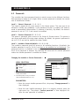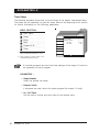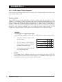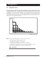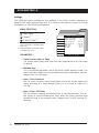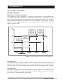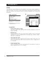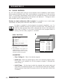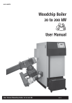
1
KOOLMASTER LS ENVIRONMENTAL MANAGEMENT SYSTEM CONTROLLER Read this guide carefully before using the controller. SERIAL NUMBER: DATE: R00 KOOLMASTER LS NOTICE Every effort has been made to ensure that this manual is complete, accurate and up-to-date. The information contained in it is however subject to change without notice due to further developments. 2 KoolMaster-LS rev.00 KOOLMASTER LS 1. INTRODUCTION ................................................................................. 6 1.1 Precautions ............................................................................................ 6 1.2 Symbols of the Manual ........................................................................... 6 1.3 Controller’s Overview ............................................................................. 7 2. MOUNTING INSTRUCTIONS ............................................................... 10 2.1 Installing the Controller on the Wall ...................................................... 10 2.2 Connections ........................................................................................ 10 2.2.1 2.2.2 2.2.3 2.2.4 Controller’s Main Wiring ................................................................................. 10 Sensor Inputs ............................................................................................... 11 Alarm Connection ......................................................................................... 11 DWR-F-1A Communication Hookup ................................................................... 11 3. USER INTERFACE ............................................................................. 12 3.1 Location of the Controls & Navigation Process ....................................... 12 3.2 Parameter Adjustment .......................................................................... 12 4. SETUP ............................................................................................. 13 4.1 Setting the Time & Date ....................................................................... 13 4.2 Passwords ........................................................................................... 14 4.3 Controller Programs & Seasons.............................................................. 15 4.4 Controller Setup .................................................................................. 16 4.5 Sensors ............................................................................................... 20 4.5.1 Temperature Sensor Assignment ...................................................................... 20 Sensor Assignment – Average Building Temperature ............................................................... Sensor Assignment – Auxiliary Outputs ................................................................................. Sensor Assignment – Heaters .............................................................................................. Sensor Assignment – Air Inlets ............................................................................................ 4.5.2 4.6 20 21 21 22 Sensor Calibration ......................................................................................... 23 Relay Assignment ................................................................................. 24 4.6.1 4.6.2 Principle of Operation .................................................................................... 24 Fan Stages’ Relay Assignment ......................................................................... 24 Fan Stage Relays ............................................................................................................... 25 Timer Relays .................................................................................................................... 26 Variable Outputs ................................................................................................................ 27 4.6.3 4.6.4 Tunnel & Vent Doors’ Relay Assignment ............................................................ 28 Heaters’ Relay Assignment ............................................................................. 29 Heat Zone Assignment ....................................................................................................... 29 4.6.5 Clock Outputs’ Relay Assignment ..................................................................... 30 Clock Output Relays .......................................................................................................... 31 Common Relays ................................................................................................................ 31 4.6.6 4.7 Low Pressure Alarm ...................................................................................... 32 Version ................................................................................................ 32 KoolMaster-LS rev.00 3 KOOLMASTER LS 5. TEMPERATURE SETTINGS ................................................................... 33 6 5.1 Temperature Set Point .......................................................................... 33 5.2 Temperature Curve ............................................................................... 34 VENTILATION & COOLING SETTINGS ................................................ 36 6.1 Minimum Ventilation ............................................................................ 36 6.1.1 Minimum Ventilation Cycles ............................................................................ 36 Principle of Operation ......................................................................................................... 36 Minimum Ventilation Settings – With Variable Outputs ........................................................... 37 Minimum Ventilation Settings – Without Variable Outputs ....................................................... 38 6.1.2 Minimum Ventilation Curve ............................................................................. 39 Principle of Operation ......................................................................................................... 39 Minimum Ventilation Curve Settings – With Variable Outputs .................................................. 40 Minimum Ventilation Curve Settings – Without Variable Outputs .............................................. 40 6.2 Fan Stages .......................................................................................... 42 6.2.1 Principle of Operation .................................................................................... 42 Fan Stages ....................................................................................................................... 42 Variable Outputs ................................................................................................................ 43 6.2.2 6.3 Settings ....................................................................................................... 45 Inlets & Vent Doors .............................................................................. 46 6.3.1 Inlet Settings ................................................................................................ 46 Potentiometer Feedback from Inlets ...................................................................................... 46 Opening Compensation (Based on the Temperature) ................................................................ 46 6.3.2 Vent Doors .................................................................................................. 48 Principle of Operation ......................................................................................................... 48 Settings ........................................................................................................................... 50 6.4 Tunnel Ventilation Curtain .................................................................... 52 6.4.1 Curtain – Based on the Static Pressure ............................................................. 52 Principle of Operation ......................................................................................................... 52 Settings ........................................................................................................................... 54 6.4.2 Curtain – Timer-Based ................................................................................... 55 Principle of Operation ......................................................................................................... 55 Settings ........................................................................................................................... 56 6.4.3 Transition Between Sidewall & Tunnel Ventilation ............................................... 57 7. HEATING .......................................................................................... 58 8. AUXILIARY OUTPUTS ........................................................................ 59 9. LIGHTS ........................................................................................... 60 10. CLOCK OUTPUTS ............................................................................. 62 4 KoolMaster-LS rev.00 KOOLMASTER LS 11. RELATIVE HUMIDITY (RH) & AMMONIA CONTROL ............................... 63 11.1 Principle of Operation ........................................................................... 63 11.1.1 Enhancing the Level of Minimum Ventilation ....................................................... 63 11.1.2 Humidity Control Using Heating Outputs ............................................................ 64 11.1.3 Kool Cel Shutoff ........................................................................................... 64 11.2 Settings .............................................................................................. 64 12. ALARMS ......................................................................................... 66 12.1 Alarm Log ............................................................................................ 66 12.2 Alarm Conditions ................................................................................. 66 12.2.1 12.2.2 12.2.3 12.2.4 Temperature Alarms ...................................................................................... 67 Static Pressure Alarms ................................................................................... 68 Alarm Settings ............................................................................................. 69 Water Spill Alarms ........................................................................................ 70 13. MONITORING FUNCTIONS ................................................................ 71 13.1 Current Conditions ............................................................................... 71 13.2 History ................................................................................................ 72 13.3 Animal Count ...................................................................................... 75 14. TEST MODE ..................................................................................... 77 15. TECHNICAL SPECIFICATIONS ............................................................ 78 16. MEMORY CARD ............................................................................... 79 16.1 Transfer Error ....................................................................................... 79 17. WORKSHEETS ................................................................................. 80 KoolMaster-LS rev.00 5 KOOLMASTER LS 1. INTRODUCTION 1.1 Precautions We strongly recommend installing supplementary natural ventilation as well as a backup thermostat on at least one cooling stage (refer to the relay panels’ wiring diagram to connect the thermostat). Although fuses at the input and outputs of the controller protect its circuits in case of an overload or overvoltage, we recommend installing an additional protection device on the controller's supply circuit. The room temperature where the controller is located MUST ALWAYS REMAIN BETWEEN 32°F AND 104°F (0°C TO 40°C). To avoid exposing the controller to harmful gases or excessive humidity, it is preferable to install it in a corridor. DO NOT SPRAY WATER ON THE CONTROLLER 1.2 Symbols of the Manual Caution. Read the following text carefully; it contains important pieces of information which, if ignored, may cause the controller to operate improperly. Pay attention. the following text contains very useful information. Press on the Current Condition button to display the main menu. Press on the proper menu selector. 6 KoolMaster-LS rev.00 KOOLMASTER LS 1.3 Controller’s Overview The KoolMaster LS is an electronic device used for environmental control in livestock buildings. It allows the user to maintain a specified target temperature by controlling the operation of ventilation and heating equipment. In combination with external relay panels, the controller can operate the following inputs and outputs: OUTPUTS : -Up to 8 16 4 4 1 12 56 On/Off relays and 2 variable outputs to operate: heating stages; fan stages & Kool Cels; clock outputs; auxiliary outputs; tunnel curtain output; potentiometer feedback inlets or 1 vent door output (based on the static pressure); INPUTS: - 8 1 1 1 1 1 inside temperature sensors; outside temperature sensor; static pressure sensor; humidity sensor; ammonia sensor; water meter. Refer to the wiring diagram enclosed at the end of this manual to connect the various devices on the controller’s inputs & outputs. KoolMaster-LS rev.00 7 KOOLMASTER LS MAIN FEATURES: SIMPLIFIED NAVIATION Menu selection buttons that are directly pointing to the controller menus considerably simplifies the navigation through the various controller menus. VERY LARGE LCD DISPLAY A large LCD screen provides an efficient interface for displaying, monitoring and adjusting the parameters. MINIMUM VENTILATION CYCLE When ventilation is not required for reducing the room temperature, on-off fan outputs can operate either continuously or intermittently to reduce the level of humidity and supply oxygen to the room. TEMPERATURE AND MINIMUM VENTILATION CURVES The controller can automatically change the temperature set point and enhance the level of minimum ventilation over a given period of time as the animals get bigger. AVERAGE BUILDING TEMPERATURES LOGS (FOR THE PAST 75 DAYS) T° READINGS OF EACH SENSOR (FOR THE PAST 10 DAYS) WATER AND HEATER MONITORING A pulse input is provided to monitor the water consumption. Heater run times are also logged into an history. These values are recorded for the current day and for the previous 75 days. ALARM MANAGEMENT Alarms are provided for high-low temperatures, defective sensors and other system failures. The controller keeps in memory the 75 most recent alarms. EIGHT INDEPENDENT TEMPERATURE SENSOR INPUTS Up to eight temperature sensors can be connected to the controller in order to obtain a more accurate reading of the average room temperature and a faster reaction time. Sensors may be assigned to each heater output or to auxiliary outputs. Auxiliary outputs can be used to operate various devices such as heating units or stir fans for instance. OUTSIDE TEMPERATURE SENSOR 8 KoolMaster-LS rev.00 KOOLMASTER LS HUMIDITY CONTROL Three mechanisms can be used to compensate for a high humidity level: 1. Enhancing the level of minimum ventilation as the humidity level increases; 2. Kool-Cel or mist units can be shutoff; 3. Heaters can be activated in timer mode. AMMONIA CONTROL The controller can enhance the level of minimum ventilation if the ammonia level is too high. STATIC PRESSURE & VENT DOORS & TUNNEL CURTAIN CONTROL A static pressure input is provided to control static pressure by opening and closing the vent doors and/or tunnel curtain. CONTROL OF AIR INLET MOVEMENT If the controller is used in combination with one or more DWR-F-1A devices, the movement of air inlets can be coordinated with the operation of the fans using a potentiometer located on the panel drive. This allows the air inlets to be adjusted correctly, without the influence of uncontrollable factors such as wind or air from adjoining rooms. PASSWORD PROTECTION A password can be enabled to restrict access to the controller setup functions. BACKUP BATTERY A backup battery allows the unit to keep time in case of a power failure. OVERLOAD AND OVERVOLTAGE PROTECTION Resettable fuses are provided at low-voltage inputs and outputs of the controller to protect its circuitry in the case of an overload or overvoltage. COMPUTER CONTROL The controller can be connected to a computer, thus making it possible to centralize the management of information and diversify control strategies. TEST MODE A test mode allows you to simulate temperature changes and verify controller performances. KoolMaster-LS rev.00 9 KOOLMASTER LS 2. MOUNTING INSTRUCTIONS 2.1 Installing the Controller on the Wall Fasten the four metal brackets on the mounting holes located behind the controller using the four screws (included with the controller). Mount the enclosure on the wall using four other screws. The enclosure must be mounted in a location that will allow the cover to be completely opened right up against the wall. Push on the locking devices to open the enclosure as illustrated. LOCKING DEVICE 2.2 Connections 2.2.1 Controller’s Main Wiring Refer to the wiring diagram enclosed with this user's manual to connect the controller. Drill holes at the bottom of the enclosure to pass the wires. Watertight connectors must also be installed to prevent water from entering in the enclosure. Do not make any holes at the side and top of the enclosure. ALL WIRING MUST BE DONE BY AN AUTHORIZED ELECTRICIAN AND MUST COMPLY WITH APPLICABLE CODES, LAWS AND REGULATIONS. MAKE SURE POWER IS OFF BEFORE DOING ANY WIRING TO AVOID ELECTRICAL SHOCKS AND EQUIPMENT DAMAGE. 10 KoolMaster-LS rev.00 KOOLMASTER LS 2.2.2 Sensor Inputs Sensors operate at low voltage and are isolated from the supply. Make sure that sensor cables remain isolated from all high voltage sources. In particular, do not route the sensor cables through the same electrical knockout as other cables. Do not connect the shield from the sensor cable to a terminal or a ground. Extending a sensor: Each sensor can be extended up to 500 feet (150 meters). To extend a sensor: Use a shielded cable of outside diameter between 0.245 and 0.260 in (6.22 and 6.60 mm) (the cable dimensions should not be under 18 AWG) to ensure the cable entry is liquid tight. Do not ground the shielding. It is preferable to solder the cable joint to ensure a proper contact between the two cables. Do not run sensor cables next to other power cables. When crossing over other cables, cross at 90°. Defective temperature sensor: An alarm is generated when a defective sensor is detected. The defective sensors are identified in the "Alarm Log" menu. Refer to chapter 12 for further information on the alarms. 2.2.3 Alarm Connection There are two types of alarms on the market. One type activates when current is cut off at its input, whereas the other activates when current is supplied at its input. For an alarm of the first type, use the NC terminal as shown on the wiring diagram. For an alarm of the second type, use the NO terminal. 2.2.4 DWR-F-1A Communication Hookup If external DWR-F-1A modules are used to control the air inlet, an identification number must be selected on each module. These numbers are predefined as shown on the table beside. Air inlet DWR-F-1A ID # inlet 1 ID #4 inlet 2 ID #5 ... ... inlet 12 ID #15 KoolMaster-LS rev.00 11 KOOLMASTER LS 3. USER INTERFACE 3.1 Location of the Controls & Navigation Process Menu Selectors Menus LCD Screen Navigation Buttons Adjustment Buttons - Menu Selection: Eight selection buttons directly points at the various menus shown on screen. Use these buttons to select the desired menus; press Back as required to return to the previous menus. - Main Menu / Current Conditions: Besides showing the outputs & sensors’ actual conditions, pressing the Current Conditions button also directs to the controller’s main menu; the main menu is displayed at the left handside of the screen. - LCD Screen & Screen Contrast: The large LCD display gives the current readings and displays the parameters. The screen contrast can be modified with the potentiometer located behind the screen. Open the controller’s front panel to access the potentiometer. LCD CONTRAST POTENTIOMETER - Led Display: The red screen display is used to show the current building temperature, the static pressure level and/or the ongoing fan stage. Refer to section 4.4 to choose the pieces of information to be displayed. 3.2 Parameter Adjustment Use the navigation buttons to select the desired parameters on screen. Parameters that can be modified blinks when selected; use the adjustment buttons to change their values. Non-blinking values are readings that cannot be changed. 12 KoolMaster-LS rev.00 KOOLMASTER LS 4. SETUP 4.1 Setting the Time & Date Main menu Time&Date Time and Date Menu Selection: Main menu ○ ○ ○ ○ ○ ○ ○ ○ ○ ○ ○ Time & Date ○ ○ ○ ○ ○ ○ ○ ○ a Wed May 12 200X 12 : 12 : 12 AM a The time and date can only be modified by the Grower or by the Installer (sec. 4.2). Use to navigate Parameters : - Press the right-arrow key once to select the first parameter. - Use the adjustment buttons to adjust the day of the week. - Press the right-arrow key to step to the next item. - Proceed in similar fashion to set the whole time and date. KoolMaster-LS rev.00 13 KOOLMASTER LS 4.2 Passwords The controller has three password levels to restrict access to the different functions. Each password is made up of 4 digits. When a correct password is entered, the current user is identified as follows: Level 1 – Viewer’s Password : 1 - 1 - 1 - 1 The viewer’s password only gives access to the Viewer menus. This user type is not allowed to modify any parameter. If the password function is enabled, the viewer’s mode is automatically selected after 15 minutes of inactivity. By default, the viewer’s password is set to 1-1-1-1 and cannot be modified. Level 2 – Grower’s Password : 2 - 2 - 2 - 2 The grower’s password gives access to the Viewer & Grower menus. The grower is can access and modify the main output settings. By default, the grower’s password is set to 2-2-2-2 and can be modified as shown below. Level 3 – Installer’s Password (default = 0 - 0 - 0 - 0) The installer’s password gives full access to all controller functions. By default, the installer password is set to 0-0-0-0 and has to be modified to be functional. The password function is disabled if the installer’s password remains unchanged: once the 0-0-0-0 password is entered, the controller will never ask for another password unless the installer password is modified as follows: Changing the Installer or Grower Passwords a Main menu Setup MENU SELECTION: Password Main menu ○ ○ ○ ○ ○ ○ ○ Setup ○ ○ ○ ○ ○ ○ ○ ○ ○ Current mode ○ ○ ○ ○ ○ ○ ○ ○ ○ ○ ○ ○ ○ ○ ○ ○ ○ ○ ○ Installer ○ b ○ Password ○ Change User Change Password 0 * * * * * * * Password a The passwords can only be modified by the installer. b The Setup menu is only accessible from the Installer mode (sec. 4.2). Use to navigate PARAMETERS: » Enter the current installer password first; the prompt “Change password” is then displayed. » Enter the new installer password. Once it is properly entered, press the right-arrow key. The prompt “Confirm password” is then displayed. Reenter the new password to validate it. 14 KoolMaster-LS rev.00 KOOLMASTER LS 4.3 Controller Programs & Seasons PROGRAM DEFINITION: Programs allow to change the fan and heater selection according to the animal age: as animals are getting bigger and occupy a larger section of the room, a greater number of fans, heaters and temperature sensors can be selected for instance. Up to 4 controller programs allow to set the following settings in advance: - fan selection for fan stages 1 to 4 (sec. 4.6.2); - heater selection (sec. 4.6.4); - selection of sensors for the average building temperature (sec. 4.5). The following procedure shows how to select which program to use. SEASON DEFINITION: The start and stop temperatures of heating and ventilation stages can be set separately for summer and winter seasons. Season changes are signalled by the user as explained below. Selecting the Current Program & Season Main menu MENU SELECTION: Grower Main menu ○ ○ ○ ○ ○ ○ ○ ○ ○ Grower a ○ ○ ○ ○ ○ ○ ○ ○ ○ ○ ○ ○ ○ ○ ○ ○ ○ ○ ○ ○ ○ ○ ○ ○ ○ ○ ○ ○ ○ Temp Curve Min Vent Set Points Fan Stage Heat Stage Set Points Set Point Settings Temp Set Point Current Day Temp Curve Program Select Temp Settings 80.0 °F 1 day Off Program A Winter a The Grower menu is only accessible from the Grower or Installer mode (sec. 4.2). Use to navigate PARAMETERS: » Program Select: This menu only appears if programs have been enabled in the controller setup (sec. 4.5). » Temp Settings: Select the proper season. KoolMaster-LS rev.00 15 KOOLMASTER LS 4.4 Controller Setup The following section shows how to customize the controller for your particular application. It demonstrates how to enable the controller’s inputs and outputs, and how to set other basic functions of your controller. Normally, this setup only needs to be done once. Main menu MENU SELECTION: Setup Main menu ○ ○ ○ ○ ○ ○ ○ ○ ○ ○ Setup ○ ○ ○ ○ ○ ○ ○ ○ ○ ○ ○ ○ ○ ○ ○ ○ ○ ○ ○ ○ ○ ○ ○ ○ ○ ○ ○ a ○ Controller a The Setup menu is only accessible from the Installer mode (sec. 4.2). PARAMETERS: Controller Controller Setup Clear Alarms? Use RH Sensor ? Use Outside Sensor? Use Ammonia Sensor? Scale (per mA) No Read No Ctrl 2.5 ppm Vent Mode PreOpen Vents Static Set. #2 SP 10 sec None Use Variable ? Yes V1 Min Speed 10 % V2 Min Speed 10 % Use to navigate » Clear Alarms? Select “Yes” to reset the Alarm Log. » Use Relative Humidity?: Select "Read" if a humidity sensor is used to provide the humidity reading. Select “Ctrl” to enable the humidity control functions (see chapter 12). Select “No” to disable the sensor. » Use Outside Temperature Sensor? Select "Yes" if an outside temperature sensor is connected to the controller. » Use Ammonia Sensor? Select "Read" if an ammonia sensor is used to provide the ammonia reading. Select “Ctrl” to enable the ammonia control functions (see chapter 12). Select “No” to disable the sensor. Scale per mA Select the rate of ammonia that is detected per milliampere (mA). Ranges from 1.0 to 12.5 ppm/mA. » Vent Doors / Inlets Operating Mode: Select “SP” if your system uses vent doors that are controlled by the static pressure level; select “pot. Ctrl” if your controller uses potentiometer feedback air inlets. 16 KoolMaster-LS rev.00 KOOLMASTER LS Vent Doors’ Pre-Opening Delay: Select the delay that is required for the vent doors to open before the fans’ activation. Ranges from 0 to 60 seconds. This option is only shown if the vent doors’ operation operating mode is based on the static pressure. Main menu Setup Controller Controller Setup Vent Mode PreOpen Vents Static Set. #2 SP 10 sec None Use Variable ? V1 Min Speed V2 Min Speed Yes 10 % 10 % Use Tunnel? Yes Tunnel Mode SP Static Pressure Set #2: PreOpen Tunnel 30 sec Two groups of static pressure set points can be defined in adUse to navigate vanced; vent doors’ operation is based on these pressure limits. Choose whether the swap between these groups is done at a specific fan stage “Stage” or if if is done in relation with the outside temperature “T° Out”. Select “None” to disable the second group of pressure set points. Refer to section 6.4.2 for further information on this function. » Use Variable?: Select "Yes" to enable 2 variable outputs. These variable outputs are located on an external module. Variable Outputs’ Minimum Speeds: Set the absolute minimum speed of both variable outputs. » Use Tunnel? Select “Yes” to enable a tunnel curtain. Tunnel Mode: Choose whether the tunnel curtain’s opening is regulated by a timer “Time” or by the static pressure level “SP”. This menu is only accessible if the vent doors’ operation is also based on the static pressure (see above); otherwise, the timer mode is automatically selected. Tunnel Curtain’s Pre-Opening Delay Select the delay that is required for the curtain to open before the fans’ activation. Ranges from 0 to 30 seconds. This option is only shown if the tunnel curtain’s operating mode is based on the static pressure. KoolMaster-LS rev.00 17 KOOLMASTER LS » Number of Inlets: Select the proper number of potentiometer feedback air inlets. Adjustable from 1 to 12 inlets. Inlets are controlled by external DWR-F-1A modules. This menu is only accessible if the air intake is ensured by potentiometer feedback inlets (see above). » Number of Auxiliary Outputs: Select the proper number of auxiliary outputs. Ranges from 0 to 4 outputs. Main menu Setup Controller Controller Setup Number of Aux.Out. Aux.1 Mode 1 Heat Number Number Number Nb of of Fan Stages of Programs of Heaters Light Programs 10 None 12 4 Number of Clocks # Prog. Clock 1 # Prog. Clock 1 2 4 4 Use to navigate Outputs 1-4: Operating Mode: Select the function of each auxiliary output: heating or cooling purposes. » Number of Fan Stages: Select the number of fan stages. Ranges from 1 to 16 stages. » Number of Programs Select the number of controller programs. Adjustable from 1 to 4 programs: None= AB= ABC= ABCD= 1 2 3 4 program; programs; programs; programs. » Number of Heaters Select the number of heaters. Ranges from 0 to 12 heaters. » Number of Light Programs Select the number of light programs. Ranges from 0 to 8 programs. » Number of Clocks Select the number of clock outputs. Ranges from 0 to 4 outputs. Number of Programs per Output Select the proper number of timer programs used by each clock outputs. Adjustable from 1 to 8 programs. 18 KoolMaster-LS rev.00 KOOLMASTER LS » Number of Inside Temperature Sensors Select the number of inside temperature sensors. Ranges from 1 to 8 sensors. » Number of Relays Select the total number relays in use (including the controller’s internal and external relays): 30, 40 or 56 relays. Main menu Setup Controller Controller Setup Number of Sensors Number of Relays Temperature Units Static Press Units Water Meter Units Time Format 8 40 °F WC Gal AM-PM Show on 4 Digit Display, Average T° Yes Static Press. No Fan Stage No Use to navigate » Measurement units: Temperature: Celsius / Fahrenheit; Water: Gallons / Liters; S.Pressure: Inches of water (“WC) / Pascal. Time format: AM/PM / 24 hours; » LED display Choose which pieces of information are shown on the red light display: Average Temperature: Static Pressure: Current fan stage: Yes/No Yes/No Yes/No KoolMaster-LS rev.00 19 KOOLMASTER LS 4.5 Sensors 4.5.1 Temperature Sensor Assignment The user must determine which temperature sensors are used to control/monitor the fan stages, heating stages, auxiliary outputs and air inlets. These outputs all operate according to the average reading of their assigned temperature probes. Worksheets are available at the end of this manual to write down the sensor assignment for each output. Sensor Assignment – Average Building Temperature Fan stages’ operation and temperature alarms are both based on the average reading of these sensors. The building temperature sensor selection is defined separately for each program in use. Refer to section 4.3 for further information on the programs. Main menu Setup MENU SELECTION: Sensor Average T° Average T° Sensor Select Main menu ○ ○ ○ ○ ○ ○ ○ Setup ○ ○ ○ ○ ○ ○ ○ ○ ○ ○ ○ ○ ○ ○ ○ ○ ○ ○ ○ ○ ○ ○ ○ ○ ○ ○ ○ ○ ○ ○ ○ ○ ○ ○ ○ ○ ○ ○ ○ ○ ○ ○ Sensors for : a ○ Sensor ○ ○ ○ ○ ○ ○ ○ Average T° Program A 1 2 3 6 7 8 4 5 a The Setup menu is only accessible from the Installer mode (sec. 4.2). PARAMETERS : » If more than one program is used, the controller for a program selection; the building temperature sensors are selected separately for each program. » Put a check mark to identify the sensors that are used to read the average building temperature of the selected program. Only the probes that have been enabled in the controller setup are displayed (sec. 4.4). 20 KoolMaster-LS rev.00 KOOLMASTER LS Sensor Assignment – Auxiliary Outputs Auxiliary outputs use the average temperature of their assigned sensors to operate. Select the sensors that are used for the operation of each output as follows: MENU SELECTION: Main menu Setup Main menu ○ ○ ○ ○ ○ ○ ○ Setup ○ ○ ○ ○ ○ ○ ○ ○ ○ ○ Sensor ○ ○ ○ ○ ○ ○ ○ ○ ○ ○ ○ ○ ○ ○ ○ ○ ○ ○ ○ ○ ○ ○ ○ ○ ○ ○ ○ ○ ○ ○ ○ ○ ○ ○ ○ a ○ Sensor ○ ○ ○ ○ Auxiliary Auxiliary Out Sensor Select Sensors for : Auxiliary b a The Setup menu is only accessible from the Installer mode (sec. 4.2). Aux.1 1 2 3 6 7 8 4 5 b Only accessible if auxiliary outputs are enabled (sec. 4.4). PARAMETERS: » Select the desired auxiliary output. » Put check mark (s) to select the auxiliary output’s sensor(s) Sensor Assignment – Heaters The heaters operate according to the average reading of their assigned temperature sensors. Make the sensor selection separately Main menu for each heater. Setup Sensor MENU SELECTION: Heater Heater Sensor Select Main menu ○ ○ ○ ○ ○ ○ ○ Setup ○ ○ ○ ○ ○ ○ ○ ○ ○ ○ ○ ○ ○ ○ ○ ○ ○ ○ ○ ○ ○ ○ ○ ○ ○ ○ ○ ○ ○ ○ ○ ○ ○ ○ ○ ○ ○ ○ ○ ○ ○ ○ a ○ Sensor ○ ○ ○ ○ ○ ○ ○ Sensors for : Heater 1 1 2 3 6 7 8 4 5 Heaters a The Setup menu is only accessible from the Installer mode (sec. 4.2). PARAMETERS: » Select the desired heater. » Put check mark (s) to select the heating output’s sensor(s) KoolMaster-LS rev.00 21 KOOLMASTER LS Sensor Assignment – Air Inlets The air inlets operate according to the average reading of their assigned temperature sensors. Select the sensors separately for each inlet. MENU SELECTION: Main menu Setup Main menu ○ ○ ○ ○ ○ ○ ○ ○ Setup ○ ○ ○ ○ ○ ○ ○ ○ ○ ○ ○ ○ ○ ○ ○ ○ ○ ○ ○ ○ ○ ○ ○ ○ ○ ○ ○ ○ ○ ○ ○ ○ ○ ○ ○ ○ ○ ○ ○ ○ ○ Sensor ○ ○ ○ ○ ○ ○ Inlets Sensor ○ a ○ Inlet Heater Sensor Select Sensors for : b a The Setup menu is only accessible from the Installer mode (sec. 4.2). 2 3 6 7 8 b Only accessible if air inlets are enabled (sec. 4.4). PARAMETERS : » Select the desired air inlet. » Put check mark (s) to select the selected inlet’s sensor(s) 22 KoolMaster-LS rev.00 Heater 1 1 4 5 KOOLMASTER LS 4.5.2 Sensor Calibration The reading of every sensor can be slightly adjusted by the user in order to obtain accurate and uniform readings of all sensors. Main menu MENU SELECTION: Setup Main menu ○ ○ ○ ○ ○ ○ ○ Setup ○ ○ ○ ○ ○ ○ ○ ○ ○ ○ ○ ○ ○ ○ ○ ○ ○ ○ ○ ○ ○ ○ ○ ○ ○ ○ ○ ○ ○ ○ a ○ Calibration a The Setup menu is only accessible from the Installer mode (sec. 4.2). PARAMETERS : Adjust the reading of each sensor as required. Only the sensors that have previously been enabled in the controller setup are displayed (sec. 4.4). Sensor Calibrat. Calibration Sensor 1 0.0 Sensor 2 0.0 Sensor 3 0.0 Sensor 4 0.0 Sensor 5 0.0 Sensor 6 0.0 Sensor 7 0.0 Sensor 8 0.0 Outside Temperature 0.0 Relative Humidity 0 Static Pressure .000 Water Meter 1 Ammonia 0.0 to navigate Use °F °F °F °F °F °F °F °F °F % WC g/p ppm » Temperature Sensors: The reading of each inside and outside temperature sensor can be adjusted of ±3 °F (±1.7 °C). » Relative Humidity Sensor: The humidity sensor reading can be adjusted of ±3 %. » Static Pressure Sensor: The static pressure sensor reading can be adjusted of±0.030 "WC (±7 Pa). » Water Meters: The user has to indicate the water flow per pulse of the water meter. It can be adjusted from 1 to 100 gallons (or liters) per pulse. » Ammonia Sensor: The ammonia sensor reading can be adjusted of ±10 ppm. KoolMaster-LS rev.00 23 KOOLMASTER LS 4.6 Relay Assignment 4.6.1 Principle of Operation The controller can monitor up to 56 On/Off relays and 2 variable outputs. Refer to the Controller Setup chapter (sec. 4.4) to enable the proper number of relays. The following procedure shows how to link up the relays with the various stages and outputs. Refer to the wiring diagram enclosed with this manual to connect the relay panels to the controller and to wire the different loads. Worksheets are available at the end of this manual to write down the relay assignment. 4.6.2 Fan Stages’ Relay Assignment This section shows how to assign fan stages’ relays. It also demonstrates how to enable variable outputs and timer-based relays within fan stages. CONTROLLER PROGRAMS: Each controller program uses a different fan selection for fan stages 1 to 4. Therefore, the relay assignment of these four stages must be done separately for each program in use. Refer to section 4.3 for further information on the programs. TIMER-BASED RELAYS: Timer-based relays can be associated with fan stages. These relays are activated, following a timer. They start operating at their stage’s start temperature. This feature is normally used to activate timer-based devices that need to follow the same progression as fan stages, such as misters or Kool Cels for instance. Following sections shows how to enable timer-based relays how to set the timers’ running times. VARIABLE OUTPUTS: Up to two variable outputs can be used to provide variable ventilation within fan stages. The variable output assignment allows to determine how and when these outputs are activated. The output’s status must be specified for each fan stage as follows: Variable mode:: the variable output is activated at its minimum intensity when its associated fan stage starts. It increases in speed as the fan stage progresses. On/Off mode: the variable output acts as an ON/OFF output. It is activated at its full capacity when its associated fan stage starts. 24 KoolMaster-LS rev.00 KOOLMASTER LS Fan Stage Relays The following steps show how to make the fan stages’ relay selection and how to enable timer-based relays within the fan stages. Refer to the beginning of this section for further information on the following parameters. Main menu Setup Relay Program Fan Fan Stage Relay Select Timer Variable Relays for : 1 MENU SELECTION: Main menu ○ ○ ○ ○ ○ ○ ○ Setup ○ ○ ○ ○ ○ ○ ○ ○ ○ ○ ○ ○ ○ ○ ○ ○ ○ ○ ○ ○ ○ ○ ○ ○ a ○ ○ ○ ○ ○ ○ ○ ○ ○ ○ ○ ○ ○ ○ ○ ○ ○ ○ ○ ○ ○ ○ ○ ○ ○ ○ ○ ○ ○ ○ ○ ○ ○ ○ ○ ○ ○ ○ ○ Relay ○ ○ ○ Stage 1B 2 3 4 5 --- --- --- --- 6 --- 7 --- 8 --- 9 --- 10 --- 11 --- 12 --- 13 --- 14 --- 15 --- 16 --- 17 --- 18 --- 19 --- 20 --- Use to navigate Fans ○ ○ ○ Program A-D b a The Setup menu is only accessible from the Installer mode (sec. 4.2). b Only shown if more than one controller program is used. PARAMETERS : » Select the proper fan stage amongst those that have been enabled in the Controller Setup (sec. 4.4). If the controller uses many programs, the relay selection for stages 1 to 4 is made separately for each program. The chosen program is identified by a letter; e.g. Stage 1B (fan stage 1, program B). » Assign the desired relays to the selected stage: put a check mark " " to assign an On/Off relay, select “TMR” to enable a timer-based relay, or select "- - -" for unused relays. MAKE SURE EVERY FAN STAGE HAS ASSIGNED RELAYS ! An alarm is set off whenever a fan stage that doesn't activate any relay is activated. If this situation occurs, the controller continues to operate using the relays of the previous fan stage. KoolMaster-LS rev.00 25 KOOLMASTER LS Timer Relays The following procedure shows how to set the timer of fan stages’ timer-based relays. The timers are set separately for each fan stage. Refer to the beginning of this section for further information on the following parameters. MENU SELECTION: Main menu ○ ○ ○ ○ ○ ○ ○ Setup ○ ○ ○ ○ ○ ○ ○ ○ ○ ○ ○ ○ ○ ○ ○ ○ ○ ○ a ○ ○ ○ ○ ○ ○ ○ ○ ○ ○ ○ ○ ○ ○ ○ ○ ○ ○ ○ ○ ○ ○ ○ ○ ○ ○ ○ ○ ○ ○ ○ ○ ○ ○ ○ ○ ○ ○ ○ ○ ○ ○ ○ ○ ○ ○ Relay ○ ○ ○ ○ ○ ○ ○ ○ ○ ○ ○ ○ Fans ○ ○ ○ Program A-D ○ ○ ○ ○ ○ ○ ○ ○ Main menu Setup Relay Fan Timer Timer Settings Stage Number : Program Select: On Time : Off Time : 2 A 15 sec 0 sec b ○ Timer a The Setup menu is only accessible from the Installer mode (sec. 4.2). b Only shown if more than one controller program is used. Use to navigate If controller programs are used, the timer settings of fan stages 1-4 must be set separately for each program. PARAMETERS : » Stage Number: Select the desired fan stage. » Program Select: If programs are used, select the proper program (for stages 1-4 only); » On / Off Times: Set the timer’s running and stop times to the desired value. 26 KoolMaster-LS rev.00 KOOLMASTER LS Variable Outputs The following procedure shows how to enable the variable outputs within fan stages. MENU SELECTION: Main menu ○ ○ ○ ○ ○ ○ ○ Setup ○ ○ ○ ○ ○ ○ ○ ○ ○ ○ ○ ○ ○ ○ ○ ○ ○ ○ a ○ ○ ○ ○ ○ ○ ○ ○ ○ ○ ○ ○ ○ ○ ○ ○ ○ ○ ○ ○ ○ ○ ○ ○ ○ ○ ○ ○ ○ ○ ○ ○ ○ ○ ○ ○ ○ ○ ○ ○ ○ ○ ○ ○ ○ ○ Relay ○ ○ ○ ○ ○ ○ ○ ○ ○ ○ ○ ○ Fans ○ ○ ○ Program A-D ○ ○ ○ ○ ○ ○ Variables ○ ○ b ○ C Variable Main menu Setup Relay Fan Variable Settings Stage Number : Program Select: 2 A Variable 1: Variable 2: Off Off a The Setup menu is only accessible from the Installer mode (sec. 4.2). b Only shown if more than one controller program is used. c Only shown if variable outputs are enabled (sec. 4.4). Use to navigate If controller programs are used, the variable output selection for fan stages 1-4 is made separately for each program. PARAMETERS : » Stage Number: Select the desired fan stage. » Program Select: If programs are used, select the proper program (for stages 1-4 only); » Variable Output Status: Set the status of both variable outputs within the selected fan stage as follows: Var.: the variable output is activated at its minimum intensity when its associated fan stage starts. It increases in speed as the fan stage progresses. ON: OFF: the variable output acts as an ON/OFF output. It is activated at its full capacity when its associated fan stage starts. the variable output is not activated. KoolMaster-LS rev.00 27 KOOLMASTER LS 4.6.3 Tunnel & Vent Doors’ Relay Assignment Two relays must be assigned to each vent doors and tunnel curtain outputs: a closing relay and an opening relay. Some of your controller relays have specially been designed for this purpose – as shown beside. These relays prevent activating both the opening and closing relays simultaneously. MENU SELECTION: Main menu Setup Main menu ○ ○ ○ ○ ○ ○ ○ ○ ○ ○ Setup ○ ○ ○ ○ Relay ○ ○ ○ ○ ○ ○ ○ ○ ○ ○ ○ Tunnel Tunnel Curtain Relay Select a ○ ○ ○ ○ ○ ○ ○ ○ ○ ○ ○ ○ ○ ○ ○ ○ ○ ○ ○ ○ ○ ○ ○ ○ ○ ○ Relay ○ ○ ○ ○ ○ ○ Relays for : Tunnel b / or Vent Doors a The Setup menu is only accessible from the Installer mode (sec. 4.2). b Only shown if the tunnel curtain or vent doors are enabled (sec. 4.4). b Open Curt 1 --- 2 --- 3 --- 4 --- 5 --- 6 --- 7 --- 8 --- 9 --- 10 --- 11 --- 12 --- 13 --- 14 --- 15 --- 16 --- 17 --- 18 --- 19 --- 20 --- Use to navigate PARAMETERS : » Select the output’s opening relay” Relays for : Open Curt (or Open Vent)”. » Put a check mark to select the output’s opening relay. » Select the output’s closing relay “Relays for : Close Curt. (or Close Vent)” » Put a check mark to select the output’s closing relay. 28 KoolMaster-LS rev.00 KOOLMASTER LS 4.6.4 Heaters’ Relay Assignment Select the relays that are associated with each activated heater as follows: MENU SELECTION: Main menu Setup Main menu ○ ○ ○ ○ ○ ○ ○ Setup ○ ○ ○ ○ ○ ○ ○ ○ ○ ○ ○ ○ ○ ○ ○ ○ ○ ○ ○ ○ ○ ○ ○ ○ ○ ○ ○ ○ ○ ○ ○ ○ ○ ○ ○ ○ ○ ○ ○ ○ ○ ○ Relay ○ ○ ○ ○ ○ ○ ○ Relay ○ a Heater a The Setup menu is only accessible from the Installer mode (sec. 4.2). PARAMETERS : » Select the desired heater. Heater Heater Relay Select Relays for : Heater 1 1 --- 2 --- 3 --- 4 --- 5 --- 6 --- 7 --- 8 --- 9 --- 10 --- 11 --- 12 --- 13 --- 14 --- 15 --- 16 --- 17 --- 18 --- 19 --- 20 --- Use to navigate » Put check mark(s) to select the heater’s relay(s). Heat Zone Assignment Each controller program uses a different selection of heaters. The heater selection must thus be specified separately for each program. Refer to section 4.3 for further information on the programs. MENU SELECTION: Main menu Main menu ○ ○ ○ ○ ○ ○ ○ Setup ○ ○ ○ ○ ○ ○ ○ ○ Setup ○ ○ ○ ○ ○ ○ ○ ○ ○ ○ ○ ○ ○ ○ ○ ○ ○ ○ ○ ○ ○ ○ a ○ Heat Zone b a The Setup menu is only accessible from the Installer mode (sec. 4.2). b Only shown if more than one controller program is used and if heaters are enabled. PARAMETERS : Heat Zone Heaters Zone Selection Program Select Program A 1 --- 2 --- 3 --- 4 --- 5 --- 6 --- 7 --- 8 --- 9 --- 10 --- 11 --- 12 --- Use to navigate » Select the desired program. » Put a check mark to identify which heating output is used within the selected program. KoolMaster-LS rev.00 29 KOOLMASTER LS 4.6.5 Clock Outputs’ Relay Assignment The following procedure shows how to assign clock outputs relays and shows how the common relays work. Common Relays: It is possible to link up the activation of various outputs with the activation of clock outputs; i.e. all outputs sharing a common relay must be activated simultaneously for the relay to switch. This allows to match the activation of a device with the activation of a clock output that is disabled during nightime or on specific days of the week for instance. Thus, the device operates according to its particular settings and stops when the clock output is disabled. This is true for all type of outputs except for fan stages and cooling outputs: their relays are not affected by the common relays. Example : Deactivating an output during night: The following example shows how to deactivate an output during night. 1. 2. 3. The first heating output uses the 6th relay. The 6th relay is also used by clock output 1 and is defined as being a common relay. OUTPUT/ RELAY # 5 6 Heater 1 X Clock output 1 X Common relays X 7 Clock output 1 has been defined to stop during night. Results : The heating output operates following its own settings as long as the first clock output is active. Since clock output 1 is disabled during night, the first heater returns to a stop during night as well. 30 KoolMaster-LS rev.00 KOOLMASTER LS Clock Output Relays Main menu MENU SELECTION: Setup Main menu ○ ○ ○ ○ ○ ○ ○ ○ ○ ○ ○ ○ ○ Setup ○ ○ ○ ○ Relay ○ ○ ○ ○ ○ ○ ○ ○ ○ ○ ○ a ○ ○ ○ ○ ○ ○ ○ ○ ○ ○ ○ ○ ○ ○ ○ ○ ○ ○ ○ ○ ○ ○ ○ ○ ○ ○ Common Relays Relay ○ ○ ○ Clock b a The Setup menu is only accessible from the Installer mode (sec. 4.2). b Only shown if clock outputs are enabled (sec. 4.4). Clock Clock Relay Select Relays for : Clock 1 1 --- 2 --- 3 --- 4 --- 5 --- 6 --- 7 --- 8 --- 9 --- 10 --- 11 --- 12 --- 13 --- 14 --- 15 --- 16 --- 17 --- 18 --- 19 --- 20 --- Use PARAMETERS : to navigate » Select the desired clock output. » Put check mark(s) to select the clock output’s relay(s). Common Relays When a common relay is conjointly assigned to a clock output and to any other output, all outputs sharing this relay must be activated simultaneously for the relays to switch. MENU SELECTION: Main menu ○ ○ ○ ○ ○ ○ ○ Setup ○ ○ ○ ○ ○ ○ ○ ○ ○ ○ ○ ○ ○ ○ ○ ○ ○ ○ ○ ○ ○ ○ ○ ○ ○ ○ ○ ○ ○ ○ ○ ○ ○ ○ ○ ○ ○ ○ ○ ○ ○ ○ ○ ○ ○ ○ ○ ○ ○ ○ ○ ○ ○ ○ a ○ Main menu Setup Relay Clock Common Rel Clock Common Relay Select Relay ○ ○ ○ ○ ○ ○ ○ 1 --- 2 --- 3 --- 4 --- 5 --- 6 --- 7 --- 8 --- 9 --- 10 --- a The Setup menu is only accessible from the Installer mode (sec. 4.2). 11 --- 12 --- 13 --- 14 --- 15 --- b Only shown if clock outputs are enabled (sec. 4.4). 16 --- 17 --- 18 --- 19 --- 20 --- Clock ○ ○ ○ ○ ○ ○ b ○ Common Relays Use to navigate » Put check mark(s) to enable common relays. KoolMaster-LS rev.00 31 KOOLMASTER LS 4.6.6 Low Pressure Alarm The user can assign a relay that switches in case of a Low Static Pressure Alarm. This relay may be used to activate a fan for instance. MENU SELECTION: Main menu Main menu ○ ○ ○ ○ ○ ○ ○ Setup ○ ○ ○ ○ ○ ○ ○ ○ ○ ○ Setup ○ ○ ○ ○ ○ ○ ○ ○ ○ ○ ○ ○ ○ ○ ○ ○ ○ ○ ○ ○ ○ ○ ○ ○ ○ ○ ○ ○ ○ ○ ○ ○ ○ ○ ○ ○ ○ Relay ○ ○ ○ Relay a Lo Static Alarm Low Alarm Lo Static Press Alarm Relay b a The Setup menu is only accessible from the Installer mode (sec. 4.2). b Only shown if vent doors are enabled (sec. 4.4). PARAMETERS : 1 --- 2 --- 3 --- 4 --- 5 --- 6 --- 7 --- 8 --- 9 --- 10 --- 11 --- 12 --- 13 --- 14 --- 15 --- 16 --- 17 --- 18 --- 19 --- 20 --- Use to navigate » Put a check mark to identify which relay(s) switches in case of a low pressure alarm. 4.7 Version This menu allows to display your controller’s version number. This piece of information is useful to get technical support that suits your specific controller’s version. Main menu Setup MENU SELECTION: Version Main menu ○ ○ ○ ○ ○ ○ ○ Setup ○ ○ ○ ○ ○ ○ ○ ○ ○ ○ ○ ○ ○ ○ ○ ○ ○ ○ ○ ○ ○ ○ ○ ○ ○ ○ ○ ○ ○ ○ a ○ KoolMaster LS Version SETTINGS V. X.X a The Setup menu is only accessible from the Installer mode (sec. 4.2). PC-XX 32 KoolMaster-LS rev.00 KOOLMASTER LS 5. TEMPERATURE SETTINGS 5.1 Temperature Set Point The set point is a target temperature; the activation and deactivation of the various stages is based on this reference temperature. SET POINT CURVES A temperature curve can be enabled to obtain an automatic adjustment of the temperature set point over a given period of time. The target temperature is thus always adapted to the animals’ needs as they grow. Refer to section 5.1.2 for further information on the curves. Main menu Adjusting the temperature set point: MENU SELECTION: Temp Curve Min Vent Main menu ○ ○ ○ ○ ○ ○ ○ ○ ○ Grower a ○ ○ ○ ○ ○ ○ ○ ○ ○ Grower ○ ○ ○ ○ ○ ○ ○ ○ ○ ○ ○ ○ ○ ○ ○ ○ ○ ○ ○ ○ Fan Stage Heat Stage Set Points Set Point Settings Temp Set Point Current Day Temp Curve Temp Settings 80.0 °F 1 day Off Winter Set Points a The Grower menu is only accessible from the Grower or Installer mode (sec. 4.2). Use to navigate PARAMETERS : » Temperature Set Point: Ranges from 0 °F to 100 °F (-17.8 °C to 37.8 °C). The set point can only be modified if the curve is disabled. The curve status is displayed below. Refer to section 5.1.2 to enable/disable the curve. KoolMaster-LS rev.00 33 KOOLMASTER LS 5.2 Temperature Curve The temperature curve allows an automatic adjustment of the set point over time. The set point changes using 10 steps. Each step specifies a day number and a target temperature for that day. These steps are based on the animal age. Once the 10 steps are defined, the curve must be activated. The controller then starts changing the temperature set point every hour in a linear fashion between consecutive steps of the curve. When the last step is reached, the temperature set point for that day is maintained until a new animal batch starts. SET POINT (°F) 78 76 74 72 70 68 66 64 62 60 DAYS DAY 1 DAY 10 DAY 15 DAY 20 DAY 25 DAY 30 DAY 35 DAY 40 DAY 45 GRAPHIC: Set Point Curve NOTE: Certain restrictions apply to reduce the risk of errors: - The highest possible day number is 450. - Decreasing day numbers is not allowed. - Increasing the temperature over time is not allowed. - All steps must be specified. If you don't need ten different steps, repeat the last temperature for each unnecessary step. MENU SELECTION: 34 KoolMaster-LS rev.00 KOOLMASTER LS Main menu ○ ○ ○ ○ ○ ○ ○ ○ ○ Grower a ○ ○ ○ ○ ○ ○ ○ ○ ○ Main menu ○ ○ ○ ○ ○ ○ ○ ○ ○ ○ ○ ○ ○ ○ ○ ○ ○ ○ ○ ○ Set Points Set Points ○ ○ ○ ○ ○ ○ ○ ○ ○ Grower ○ ○ ○ ○ ○ ○ ○ ○ ○ Temp. Curve a The Grower menu is only accessible from the Grower or Installer mode (sec. 4.2). PARAMETERS : ○ Temperature Temp Curve Curve Cur. Day Off day Set Point 80.0 °F day 1 80.0 °F day 10 77.0 °F day 15 72.0 °F day 20 67.0 °F day 25 65.0 °F day 30 63.0 °F day 35 60.0 °F day 40 60.0 °F day 45 60.0 °F day 50 60.0 °F Status Off Use to navigate » Current Day: The current animal age is displayed. It is possible for the user to change the animal age from here. This allows to move forward or backward into the curve. Keep in mind that all controller functions that are based on the animal age will also be affected by a change in the animal age. » Current Set Point: The current temperature set point is displayed. If the curve status is disabled below, the user can change it from here; if the curve is enabled, the actual set point, as calculated by the curve, is displayed and cannot be modified. » Days: Set the day at which each point starts being used. This number corresponds to the animal age and is adjustable from 0 to 450 days. The day value can only be changed while the curve is disabled, see below. » Set Points: Set the temperature associated with each step of the curve. These values can only be changed while the curve is disabled, see below. » Curve Status: Select “Yes” to activate the curve. Once it is enabled, the set point automatically becomes adjusted between consecutive points of the curve; for this reason, the set point and curve steps cannot be modified while the curve is active. KoolMaster-LS rev.00 35 KOOLMASTER LS 6 VENTILATION & COOLING SETTINGS 6.1 Minimum Ventilation 6.1.1 Minimum Ventilation Cycles Principle of Operation The minimum ventilation cycles are activated whenever the average room temperature is below the set point. Stage 1 fans then start operating according to a timer. Running the fans even though ventilation is not required for reducing the room temperature is useful to reduce the humidity level and supply oxygen to the room. It also prevents fans from freezing in winter. MINIMUM VENTILATION TIMER: During the minimum ventilation cycles, stage 1 fans run according to a timer as shown below. Either ON/OFF fans or variable fans can be used to ensure this type of ventilation. ON TIME ON OFF CYCLE TIME GRAPHIC: Minimum Ventilation Cycle The minimum ventilation timer is composed of an ON TIME and of a CYCLE TIME. Stage 1 fans run during the ON TIME then return to a stop until the end of the cycle. If stage 1 uses variable-speed fans, these fans will run at a speed that is especially defined for minimum ventilation cycles. 36 KoolMaster-LS rev.00 KOOLMASTER LS Minimum Ventilation Settings – With Variable Outputs Minimum ventilation parameters differ depending if variable outputs are enabled or not. The following parameters are available if variable outputs are enabled in the controller setup (sec. 4.4). MENU SELECTION: Main menu Grower Main menu ○ ○ ○ ○ ○ ○ ○ ○ ○ ○ ○ ○ Grower a ○ ○ ○ ○ ○ ○ ○ ○ ○ ○ ○ ○ ○ ○ ○ ○ ○ ○ ○ ○ ○ ○ ○ ○ ○ ○ ○ ○ ○ ○ ○ ○ ○ ○ ○ ○ ○ ○ Set Points ○ ○ ○ ○ ○ ○ ○ Min. Vent. a The Grower menu is only accessible from the Grower or Installer mode (sec. 4.2). PARAMETERS : Set Points Variable 1 Curve Variable 2 Curve Min Vent. Ventilation Minimum Variable 1 Status On Time Cycle Min Speed Curve Off On 15 sec 30 sec 30 % Variable 2 Status On Time Cycle Min Speed Curve Off On 15 sec 30 sec 30 % Use to navigate » Variable 1-2, Curve Status: The actual curve status of both variable outputs is displayed. Refer to section 6.1.2 to modify the status of both curves. » Variable 1-2, On / Cycle Times: Set the minimum ventilation timer of both variable outputs. The On an Off times range from 0 to 900 seconds and can only be modified if the minimum ventilation curve is disabled (sec. 6.1.2). » Variable 1-2, Minimum Speeds: Set the variable fan speed that is used within the minimum ventilation cycles. This parameter can only be modified if the minimum ventilation curve is disabled (sec. 6.1.2). KoolMaster-LS rev.00 37 KOOLMASTER LS Minimum Ventilation Settings – Without Variable Outputs Minimum ventilation parameters differ depending if variable outputs are enabled or not. The following parameters are available if variable outputs are disabled in the controller setup (sec. 4.4). Main menu MENU SELECTION: Grower Set Points Main menu ○ ○ ○ ○ ○ ○ ○ ○ Grower ○ ○ ○ ○ ○ ○ ○ ○ ○ ○ ○ ○ ○ ○ ○ ○ ○ ○ ○ ○ ○ ○ ○ ○ ○ ○ ○ ○ ○ ○ ○ ○ ○ ○ ○ ○ ○ ○ ○ a ○ Set Points ○ ○ ○ ○ ○ ○ ○ ○ ○ Min. Vent. Min Vent Curve Minimum Min Vent. Ventilation On Time Cycle 60 sec 300 sec Curve Off a The Grower menu is only accessible from the Grower or Installer mode (sec. 4.2). PARAMETERS : Use to navigate » On / Cycle Times Set the minimum ventilation timer. The On and Cycle times range from 0 to 900 seconds, in increments of 5 seconds. Note that the cycle time is limited by the vent doors' pre-opening delay; it must be set at a greater value than twice the pre-opening delay (sec. 4.4) and must also be greater than the On Time. This parameter can only be modified if the minimum ventilation curve is disabled (sec. 6.1.2). » Curve Status The actual minimum ventilation curve status is displayed. 38 KoolMaster-LS rev.00 KOOLMASTER LS 6.1.2 Minimum Ventilation Curve Principle of Operation - With Variable Outputs If the minimum ventilation cycles are ensured by variable fans, the fans’ speed within the cycles can automatically be increased over time by using a curve. - Without Variable Outputs: If minimum ventilation cycles are ensured by On/Off fans, the fans’ running time (On Time) can automatically be increased over time by using a curve. Curve definition: This curve allows to change the speed of the variable fans (or the running time of On/ Off fans) using 10 steps. Each step specifies a day number and a fan speed (or On Time) for that day. The curve steps are based on the animal age. Once all 10 steps are defined, the curve must be activated. The controller then changes the fan speed (or the fans’ On time) every hour in a linear fashion between consecutive steps of the curve. When the last step is reached, the speed (or the On Time) for that day is maintained until a new batch starts. VARIABLE FANS’ SPEED (OR ON TIME) WITHIN THE MIN. VENT CYCLES 70 65 60 55 50 45 40 DAYS D1 D10 D15 D20 D25 D30 D35 D40 GRAPHIC: Minimum Ventilation Curve NOTE: - Certain restrictions apply to reduce the risk of errors: The highest possible day number is 450. Decreasing day numbers is not allowed. Decreasing fan speeds (or running times) is not allowed. All ten steps must be specified. If you don't need 10 different steps, repeat the last speed for each unused step. KoolMaster-LS rev.00 39 KOOLMASTER LS Minimum Ventilation Curve Settings – With Variable Outputs MENU SELECTION: Main menu ○ ○ ○ ○ ○ ○ ○ ○ ○ ○ ○ ○ ○ ○ ○ ○ ○ ○ ○ ○ ○ ○ ○ ○ ○ ○ ○ ○ ○ ○ ○ ○ ○ ○ ○ ○ ○ ○ ○ ○ ○ ○ ○ ○ ○ ○ ○ ○ ○ Variable 1-2 Curve b Grower ○ ○ ○ ○ ○ ○ ○ a ○ Set Points ○ ○ ○ ○ ○ ○ ○ ○ ○ Min. Vent. ○ ○ ○ ○ ○ ○ ○ ○ ○ ○ a The Grower menu is only accessible from the Grower or Installer mode (sec. 4.2). b Only available if variable outputs are enabled (sec. 4.4). Main menu Grower Set Points Min Vent Var1 Curve Min Vent Variable 1 Curve Cur. Day Off day Speed 30 % day 1 10 % day 10 12 % day 15 14 % day 20 16 % day 25 18 % day 30 20 % day 35 25 % day 40 30 % day 45 35 % day 50 40 % Status Off to navigate Use PARAMETERS : » Current Day: The current animal age is displayed. It is possible for the user to change the animal age from here. This allows to move forward or backward into the curve. Keep in mind that all controller functions that are based on the animal age will also be affected by a change in the animal age. » Current Speed: The variable fan speed that is used within the minimum ventilation cycles is displayed. If the curve status is disabled below, the user can change the minimum ventilation fan speed from here; if the curve is enabled, the actual fan speed, as calculated by the curve, is displayed and cannot be modified. » Days: Set the day at which each point starts being used. This number corresponds to the animal age and is adjustable from 0 to 450 days. The day value can only be changed while the curve is disabled, see below. » Speeds: Set the fan speed associated with each step of the curve. These values can only be changed while the curve is disabled, see below. » Curve Status: Select “Yes” to activate the minimum ventilation speed curve. Once it is enabled, the variable fans’ speed, within the minimum ventilation cycles, automatically changes between consecutive steps of the curve; for this reason, the curve steps cannot be modified while the curve is active. Minimum Ventilation Curve Settings – Without Variable Outputs 40 KoolMaster-LS rev.00 KOOLMASTER LS MENU SELECTION: Main menu ○ ○ ○ ○ ○ ○ ○ ○ Grower ○ a ○ ○ ○ ○ ○ ○ ○ ○ ○ ○ ○ ○ ○ ○ ○ ○ ○ ○ ○ ○ ○ ○ ○ ○ ○ ○ ○ ○ ○ ○ ○ ○ ○ ○ ○ ○ ○ ○ ○ ○ ○ ○ ○ ○ ○ ○ ○ Set Points ○ ○ ○ ○ ○ ○ ○ ○ ○ ○ ○ ○ ○ Min. Vent. ○ ○ ○ ○ ○ ○ ○ Min. Vent. Curve b a The Grower menu is only accessible from the Grower or Installer mode (sec. 4.2). b Only available if variable outputs are disabled (sec. 4.4). PARAMETERS Main menu Grower Set Points Min Vent MinV.Curve Minimum Ventilation Curve Cur. Day 5 day On Time 17 sec day 1 15 sec day 10 30 sec day 15 45 sec day 20 60 sec day 25 75 sec day 30 90 sec day 35 105 sec day 40 120 sec day 45 135 sec day 50 150 sec Status Off to navigate Use » Current Day: The current animal age is displayed. It is possible for the user to change the animal age from here. This allows to move forward or backward into the curve. Keep in mind that all controller functions that are based on the animal age will also be affected by a change in the animal age. » Current On Time: The running time of On/Off fans, within the minimum ventilation cycles, is displayed. If the curve status is disabled below, the user can change the fans’ running time from here; if the curve is enabled, the actual On time, as calculated by the curve, is displayed and cannot be modified. » Days: Set the day at which each point starts being used. This number corresponds to the animal age and is adjustable from 0 to 450 days. The day value can only be changed while the curve is disabled, see below. » On Times: Set the running time of the fans, within the minimum ventilation cycles, for each step of the curve. These values can only be changed while the curve is disabled, see below. » Curve Status: Select “Yes” to activate the minimum ventilation curve. Once it is enabled, the fans’ On time, within the minimum ventilation cycles, automatically changes between consecutive steps of the curve; for this reason, the curve steps cannot be modified while the curve is active. KoolMaster-LS rev.00 41 KOOLMASTER LS 6.2 Fan Stages 6.2.1 Principle of Operation Fan Stages The controller can use up to 16 On-Off fan stages. These stages operate in a sequence to increase the level of ventilation as the room temperature increases. Each stage can also activate two variable outputs and a combination of timer relays for cooling purposes. The user defines a start and a stop temperature for each stage. A fan stage is activated when its start temperature is reached; it is deactivated when the room temperature decreases to its stop temperature. VENTILATION LEVEL STAGE X FANS TURN ON STAGE Y STAGE Y FANS TURN OFF STAGE Y FANS TURN ON STAGE X FANS TURN OFF STAGE X ROOM T° GRAPHIC: Ventilation Stages Fan stages’ start temperatures are defined with respect to the set point and with respect to each other. This means that when one of these values is adjusted, all the consecutive values are adjusted by the same amount. For example, if the set point is increased by 1 °F, the start temperatures for all fan stages will be increased by the same amount. The start and stop temperatures of all fan stages are set separately for summer and winter seasons. Refer to sec. 4.3 or press to select the proper season. 42 KoolMaster-LS rev.00 KOOLMASTER LS Timer Relays for Cooling Devices: Fan stages can activate relays that operate following a timer. This feature is normally used to activate timer-based devices that need to follow the same progression as fan stages, such as misters or Kool Cels for instance. Refer to section 4.6.2 to activate timer-based relays. ON TIME ON OFF OFF TIME GRAPHIC: Fan Stages’ Timer Variable Outputs Variable outputs are activated when the fan stage they are associated with starts (sec. 4.6.2). They are first enabled at their minimum speed, as defined in section 4.4, and gradually increase in speed as the room temperature increases. Their full speed is reached when the start temperature of the following fan stage is attained. FAN SPEED FANS REACH THEIR FULL SPEED 100% FANS ARE ACTIVATED AT THEIR MIN. SPEED FANS STOP MIN SPEED OFF ROOM T° GRAPHIC : Variable Fans on Ventilation Stages KoolMaster-LS rev.00 43 KOOLMASTER LS Transition between fan stages 1 and 2 : If stage 2 is an ON/OFF fan stage, the variable fans of stage 1 return to a stop when the new stage starts. If the next stage is another VARIABLE stage, the speed of stage 1 fans is brought down to its minimum speed when stage 2 starts. This ensures a smooth transition between both stages. The following graphic sums up the situation: V1 FAN SPEED 100% V1 BANDWIDTH FANS OF STAGE 1 RETURN TO THEIR MIN. SPEED WHEN STAGE 2 IS ACTIVATED. * MIN. SPEED V1 BANDWIDTH OFF ROOM T° GRAPHIC : Transition between fan stages 1 & 2 * Starting Speed - Variable outputs within Stage 1 or 2 start at the same speed as defined for the minimum ventilation cycles (sec. 6.1.1). - Variable outputs within Stage 3 and higher start at their absolute minimum speed (as defined in section 4.4). The bandwidth represents the interval over which the variable output goes from its minimum to its full speed. This is true even if full speed is never reached as in the example above. When the start temperature of stage 2 is reached, the variable output’s speed is reduced to its minimum speed. V1 bandwidth is then used to increase the fan speed as the temperature increases. When the temperature decreases below stage 2’s start temperature, the minimum fan speed is maintained until the stage's stop temperature is reached. The last fan stage must not be set as a variable stage. If it uses variable outputs, the outputs must operate as on/off fans (sec. 4.6.2). 44 KoolMaster-LS rev.00 KOOLMASTER LS 6.2.2 Settings The fan stage parameters must be set separately for both seasons (if applicable). Refer to section 4.3 to select the proper season and refer to the previous section for further information on the operation of fan stages. Main menu MENU SELECTION: Grower Set Points Main menu ○ ○ ○ ○ ○ ○ ○ ○ ○ Grower a ○ ○ ○ ○ ○ ○ ○ ○ ○ ○ ○ ○ ○ ○ ○ ○ ○ ○ ○ ○ ○ ○ ○ ○ ○ ○ ○ ○ ○ ○ ○ ○ ○ ○ ○ ○ ○ ○ ○ ○ ○ Set Points ○ ○ ○ ○ ○ ○ ○ ○ ○ ○ Fan Stage a The Grower menu is only accessible from the Grower or Installer mode (sec. 4.2). Fan Stage Fan Stage Settings Fan Stages 1 2 3 (...) Use Temperature On 80.5 °F V1 2.0 °F V2 2.0 °F On 81.5 °F Off 81.0 °F V1 2.0 °F V2 2.0 °F On 82.5 °F Off 82.0 °F to navigate PARAMETERS : Make sure the proper season is selected before making any changes in start/ stop temperatures of fan stages. Refer to sec. 4.3 to select the proper season. » Start & Stop Temperatures: Set the start and stop temperatures of each fan stage. The minimum temperature difference between two consecutive start temperatures is 0.5 °F 0.3 °C). » V1-V2 Bandwidths b: Set the number of degrees reach their full speed within widths can be adjusted from bandwidths are shown for (sec. 4.6.2). that are required for the variable outputs to the ventilation stages (sec. 6.2.1). The band0.5 to 20.0 °F (0.3 to 11.1 °C). The stages’ variable outputs operating in variable mode KoolMaster-LS rev.00 45 KOOLMASTER LS 6.3 Inlets & Vent Doors The controller can operate the air inlets / vent doors in two different ways: 1. Inlet positions can be determined by using a potentiometer feedback controller (DWR-F-1A). Refer to the installation setup section to enable these devices. In this manual, the term “Inlet” refers to an air inlet that is controlled by a DWRF-1A module. Refer to section 4.4 to enable the proper number of air inlets. 2. Inlet positions can be determined by the static pressure level. In this manual, the term "Vent Door" refers to an air inlet that is controlled by the static pressure level. Refer to section 4.4 to enable vent doors. 6.3.1 Inlet Settings Potentiometer Feedback from Inlets Up to 12 DWR-F-1A modules can be connected to the main controller; these module are used to define the air inlet positions based on the ventilation stages: as the temperature increases and new stages are activated, the inlets open or close accordingly. Refer to the DWR-F-1A’s instruction manual to program the inlet openings. The tunnel curtain output must temporarily be disabled while making the inlets’ calibration. Refer to section 4.4 to disable the tunnel. Opening Compensation (Based on the Temperature) An opening compensation can be performed on the inlets to ensure a certain uniformity in the building temperature: this function allows to slightly adjust the inlet openings when the average reading of the inlet sensors differs from the average temperature reading in the building. This compensation is expressed as a percentage per degree difference between the building’s average temperature and the average reading of the inlets’ sensors. It determines by how much the inlet must open or close to help reduce the temperature differences in the building. For each degree above or below the average temperature, the inlet opens or closes according to its compensation value. For example, if the compensation is set to 2 %/°F and the inlet sensor reading is 3 °F above the average building temperature, the inlet opens 6% further to help decrease the temperature in that zone. Refer to section 4.5.1 to assign inlets temperature sensors. 46 KoolMaster-LS rev.00 KOOLMASTER LS Inlet Compensation Settings: The following settings are only available for inlets that are controlled by external potentiometer feedback modules (DWR-F-1A). Refer to section 4.4 to enable the inlets. MENU SELECTION: Main menu Main menu ○ ○ ○ ○ ○ ○ ○ ○ Grower ○ a ○ ○ ○ ○ ○ Inlets ○ ○ ○ ○ Grower ○ ○ ○ ○ ○ ○ ○ ○ ○ ○ ○ ○ ○ ○ ○ ○ ○ ○ ○ ○ b a The Grower menu is only accessible from the Grower or Installer mode (sec. 4.2). b Accessible if inlets are enabled (sec. 4.4.) PARAMETERS : Inlets Inlet Settings Inlet 1 Comp. Inlet 2 Comp. Inlet 3 Comp. Inlet 4 Comp. Inlet 5 Comp. Inlet 6 Comp. Inlet 7 Comp. Inlet 8 Comp. Inlet 9 Comp. Inlet 10 Comp. Inlet 11 Comp. Inlet 12 Comp. Use 5 5 5 5 5 5 5 5 5 5 5 5 %/° %/° %/° %/° %/° %/° %/° %/° %/° %/° %/° %/° to navigate » Inlet Opening Compensation Set the opening compensation for each activated air inlet. Adjustable from 0 to 100 %/°F. KoolMaster-LS rev.00 47 KOOLMASTER LS 6.3.2 Vent Doors Principle of Operation Vent doors are air intake devices that are based on the static pressure level: when the pressure decreases below the low pressure set point, the vent doors close according to a timer. Likewise, when the static pressure increases above the high pressure set point, the vent doors open according to a timer. A fan stage above which vent doors remain closed can also be defined. Refer to section 4.4 to activate the vent doors. VENT DOORS OPEN STATIC PRESSURE The static pressure level goes under the Lo Pressure Set Point. The vent doors close according to a timer (Close time, Off time) The static pressure level increases above the Hi Pressure Set Point. Vent Doors Stop Opening The vent doors open according to a timer (Open time, Off time) VENT DOORS STAY STILL HIGH SET POINT (OPEN AT) Vent Doors Stop Closing VENT DOORS CLOSE LOW SET POINT (CLOSE AT) TIME GRAPHIC: Vent Doors’ Operation In minimum ventilation, the vent doors open during a pre-opening delay before the fans’ startup. Refer to section 4.4 to set the vent doors’ pre-opening delay. Static Pressure Alarm: Alarms can be set off if the static pressure level exceeds the user-defined pressure limits. Refer to section 13.2.2 to set this type of alarm. 48 KoolMaster-LS rev.00 KOOLMASTER LS Groups of static pressure settings : Two groups of static pressure settings can be defined. The second group of settings allows to use different high/low limits and different opening and closing times for the vent doors. This second group of settings starts being used either at the startup of a chosen ventilation stage or when the outside temperature decreases below a certain temperature. The following graphs sum both cases: 1. Transition between static pressure settings – based on the ventilation stages: Example: When the start temperature of stage 5 is reached, the vent doors start operating according to the second group of static pressure settings; therefore, new high and low pressure limits are used. The initial settings become used once again when the room temperature decreases below the stop temperature of stage 5. STATIC PRESSURE LIMITS HI SET POINT 2 (OPEN AT) HI SET POINT 1 (OPEN AT) LO SET POINT 2 (CLOSE AT) LO SET POINT 1 (CLOSE AT) FAN STAGE 5 STOP T° ROOM TEMPERATURE FAN STAGE 5 START T° GRAPHIC: Transition between static pressure set point groups – based on the fan stages 2. Transition between static pressure settings – based on the outside temperature: Example: When the outside temperature decreases below the outside influence temperature, a gradual transition between the two groups of static pressure settings starts being done. The second group of settings is permanently used when the outside temperature is 5°F (2,8°C) below the outside influence temperature. STATIC PRESSURE LIMITS HI SET POINT 1 (OPEN AT) HI SET POINT 2 (OPEN AT) LO SET POINT 1 (CLOSE AT) LO SET POINT 2 (CLOSE AT) 5°F (2.8°C) 50°F (27.8°C) 55°F (30.6°C) (outside t° influence) OUTSIDE TEMPERATURE GRAPHIC: Transition between static pressure set point groups – based on the outside temperature KoolMaster-LS rev.00 49 KOOLMASTER LS Settings Refer to the previous section for further information on the following parameters. Main menu MENU SELECTION: Grower Main menu ○ ○ ○ ○ ○ ○ ○ ○ Grower ○ ○ ○ ○ ○ ○ ○ ○ ○ ○ ○ ○ ○ ○ ○ ○ ○ ○ ○ ○ ○ ○ ○ ○ ○ ○ ○ ○ ○ a ○ Vent Doors b a The Grower menu is only accessible from the Grower or Installer mode (sec. 4.2). b Only accessible if vent doors are enabled (sec. 4.4). PARAMETERS : Vent Doors Vent Door Settings Close Open Close On Time Open On Time Off Time Close Door at stage .050 .080 60 60 10 6 WC WC sec sec sec Static Pressure Settings 2 Start at Stage # 6 Close at .050 WC Open at .080 WC Use to navigate » Open/Close Limits (Static Pressure Set Points): Set the static pressure level below which the vent doors close and above which they open. The opening/closing limits can be adjusted from 0 to 0.4 inches of water (0 to 100 Pa). » Close On Time: When the static pressure level decreases below the Lo pressure set point, the vent doors close during this delay. The closing time ranges from 0 to 900 seconds. » Open On Time: When the static pressure exceeds the Hi pressure set point, the vent doors open during this delay. The opening time ranges from 0 to 900 seconds. » Off Time: Once the vent doors have opened or closed (depending on the situation), they then stay still during the Off time delay. This delay ranges from 0 to 900 seconds. » Close Doors at Stage: The user can define a stage above which the vent doors always remain closed. This feature is useful for closing vent doors when a tunnel ventilation stage starts. Select "None" to deactivate this function. 50 KoolMaster-LS rev.00 KOOLMASTER LS » Static Pressure Settings 2: The following procedure shows how to set the second group of vent doors’ static pressure settings. Refer to the previous section for further information on these parameters. Note that the following menus are only accessible if the second group of pressure settings has been enabled in the installation (sec. 4.4). Start at stage: Select the fan stage at which the controller switches from its regular static pressure settings to its second group of pressure settings. This menu only is only shown if the “Stage” transition method is enabled (sec. 4.5). Outside T° Influence: Set the outside temperature below which the transition between both static pressure setting groups starts being done. This menu only is only shown if the “Out T°” transition method is enabled (sec. 4.5). Open/Close Limits (second settings): Set the static pressure level below which the vent doors close and the temperature above which they open when the second groups of static pressure settings is being used. The opening/closing limits can be adjusted from 0 to 0.4 inches of water (0 to 100 Pa). KoolMaster-LS rev.00 51 KOOLMASTER LS 6.4 Tunnel Ventilation Curtain The controller allows to control an endwall curtain for tunnel ventilation. The tunnel curtain is either controlled by the static pressure level or it operation can be based on a timer. Refer to section 4.4 to select the proper operation mode of the tunnel curtain (Timer / Static Pressure). 6.4.1 Curtain – Based on the Static Pressure Principle of Operation Beginning of the Tunnel Ventilation: The tunnel ventilation’s activation is linked with the activation of a user-defined fan stage. When the start temperature of this stage is reached, the tunnel curtain starts being adjusted according to the static pressure level. CURTAIN OPENS STATIC PRESSURE THE STATIC PRESSURE LEVEL DECREASES UNDER THE LOW LEVEL: THE CURTAIN CLOSES ACCORDING TO A TIMER (CLOSE TIME/ OFF TIME) CURTAIN STAYS STILL HIGH LIMIT THE STATIC PRESSURE LEVEL EXCEEDS THE HIGH LEVEL: THE CURTAIN STOPS OPENING THE CURTAIN OPENS ACCORDING TO A TIMER (OPEN TIME/ OFF TIME) THE CURTAIN STOPS CLOSING CURTAIN CLOSES LOW LIMIT TIME GRAPHIC : Curtain’s Operation - based on the static pressure level Timer: When the static pressure level exceeds the high pressure limit, the curtain opens during the Open Time then stays still during the Off Time. This process repeats up until the static pressure level goes back into the acceptable pressure range. The reversed process is performed when the static pressure decreases below the low pressure limit; the curtain closes during the Close Time then stays still during the Off Time. The Off Time is common to both closing and opening cycles. 52 KoolMaster-LS rev.00 KOOLMASTER LS Minimum Age: A minimum age is defined to prevent tunnel ventilation from being used when the animals are too young. The user defines the age above which the tunnel curtain mode can start to be used. The tunnel curtain never opens when the animals are below this age. High / Low Pressure Limits: The curtain opens according to a timer (Open Time & Off Time) when the pressure exceeds the high pressure limit. It closes according to another timer (Close Time & Off Time) when the pressure decreases below the low pressure limit. Static Pressure Alarm: Alarms can be set off if the static pressure level exceeds user-defined pressure limits. Refer to section 13.2.2 to set this type of alarm. KoolMaster-LS rev.00 53 KOOLMASTER LS Settings The following curtain settings are only available if the tunnel curtain’s operation is based on the static pressure level (sec. 4.4). Refer to the previous section for further information on the following parameters. MENU SELECTION: Main menu Grower Main menu ○ ○ ○ ○ ○ ○ ○ ○ Grower ○ ○ ○ ○ ○ ○ ○ ○ ○ ○ ○ ○ ○ ○ ○ ○ ○ ○ ○ ○ ○ ○ ○ ○ ○ ○ ○ ○ ○ a ○ Tunnel Curtain b a The Grower menu is only accessible from the Grower or Installer mode (sec. 4.2). b Only accessible if the tunnel curtain is enabled (sec. 4.4). PARAMETERS : Tunnel C. Tunnel Curtain Settings Tunnel Start Stage Minimum Animal Age Close Curtain at Open Curtain at Open Time Close Time Off Time Use 3 1 day .050 .080 60 60 10 WC WC sec sec sec to navigate » Tunnel Curtain starts at Stage The curtain starts being used when the start temperature of this fan stage is reached. » Minimum Age This is the animal age below which the tunnel curtain remains closed. The tunnel ventilation mode can only be enabled once this animal age is reached. Ranges from 0 to 450 days. » Open / Close Curtain at Set the static pressure limits below/above which the curtain opens and closes according to a timer. Ranges from 0 to 0.4 inches of water (0 to 100 Pa). » Open / Close / Off Times Set the curtain’s opening and closing times to the desired value. The curtain opens or closes following this timer when the static pressure level exceeds the high or low pressure limits. Ranges from 0 to 900 seconds (15 minutes). 54 KoolMaster-LS rev.00 KOOLMASTER LS 6.4.2 Curtain – Timer-Based Principle of Operation Beginning of the Tunnel Ventilation: The activation of tunnel ventilation is linked with the activation of a user-defined fan stage. When the start temperature of that stage is reached, the curtain opens according to the opening time that is associated with this stage. When half of the curtain’s opening time has elapsed, the stage’s fans are activated. The activation of every consecutive fan stages causes the curtain to open further, in accordance with the stages’ opening times. FAN STAGES FAN STAGE B TURNS OFF --------------------THE CURTAIN CLOSES DURING STAGE B’S OPENING TIME FAN STAGE B FAN STAGE B TURNS ON --------------------THE CURTAIN OPENS DURING STAGE B’S OPENING TIME THE CURTAIN STARTS OPENING THEN THE FANS OF STAGE A TURN ON FAN STAGE A TURNS OFF FAN STAGE A OFF ROOM T° GRAPHIC : Curtains’ Operation - based on the room temperature Minimum Age: The minimum age is used to prevent tunnel ventilation from being used when the animals are too young. The user defines the age above which the tunnel ventilation mode can start. The tunnel curtain never opens when the animals are under this age. Opening Times: The curtain’s opening times are associated with the activation of fan stages. When the start temperature of a stage is reached, the curtain opens according to the opening time that is associated with that stage. KoolMaster-LS rev.00 55 KOOLMASTER LS Settings The following curtain settings are only available if the tunnel curtain’s operation is based on a timer. In this case, a curtain moving time is associated with each fan stage (sec. 4.4). Refer to the previous section for further information on the following parameters. MENU SELECTION: Main menu Grower Main menu ○ ○ ○ ○ ○ ○ ○ ○ Grower ○ ○ ○ ○ ○ ○ ○ ○ ○ ○ ○ ○ ○ ○ ○ ○ ○ ○ ○ ○ ○ ○ ○ ○ ○ ○ ○ ○ ○ a ○ Tunnel Curtain b a The Grower menu is only accessible from the Grower or Installer mode (sec. 4.2). b Only accessible if the tunnel curtain is enabled (sec. 4.4). Tunnel C. Tunnel Curtain Settings Tunnel Start Stage Minimum Animal Age 3 1 day Open and Close Run Time Total Stage Stage Stage Stage Stage Stage Stage Use Run Time 2:00 3 0:30 4 0:30 5 0:30 6 0:30 7 0:30 8 0:30 9 0:30 to navigate m:s m:s m:s m:s m:s m:s m:s m:s PARAMETERS : » Tunnel Curtain starts at Stage: The tunnel curtain starts opening when the start temperature of this fan stage is reached. » Minimum Age: Animal age below which the tunnel curtain remains closed. The tunnel ventilation can only be enabled when this animal age is reached. Adjustable from 1 to 450 days. » Total Curtain Run Time: Set the total time that is required for the tunnel curtain to fully open. The sum of all opening times below cannot exceed this value. It ranges from 0 to 15 minutes. » Curtain Opening Times: Select the opening time that is associated with the activation of each fan stage. Adjustable from 0 to 15 minutes. 56 KoolMaster-LS rev.00 KOOLMASTER LS 6.4.3 Transition Between Sidewall & Tunnel Ventilation The following section describes the vent doors and curtain's behaviors during the transition between sidewall ventilation (vent doors) and tunnel ventilation. These steps are automatically performed by the controller if the tunnel curtain’s operation is also based on the static pressure (sec. 4.4). VENT DOORS TO TUNNEL : 1. Vent doors stop operating; 2. The tunnel curtain opens during the Pre-Opening time; 3. Fans of the first tunnel stage turn on; 4. The tunnel curtain automatically adjusts the static pressure level, until it reaches Lo Static Pressure Limit + 0.01 "WC; 5. Vent doors close until the static pressure level reaches Hi Static Pressure Limit - 0.01 "WC; 6. Steps 4 and 5 are repeated until the vent doors run for over 30 seconds without reaching Hi Static Pressure Limit - 0.01 "WC; The house is now in tunnel mode. TUNNEL TO VENT DOORS: 1. Tunnel fans are turned off when the temperature decreases and reaches the first non-tunnel stage; 2. The tunnel curtain automatically adjusts the static pressure level, until it reaches Hi Static Pressure Limit - 0.01 "WC; 3. Vent doors open until the static pressure level reaches Lo Static Pressure Limit + 0.01 "WC; 4. Steps 2 and 3 are repeated until the tunnel curtain runs for over 30 seconds without reaching a static pressure of Hi Static Pressure Limit - 0.01 "WC; The house is now in sidewall ventilation mode (vent doors). KoolMaster-LS rev.00 57 KOOLMASTER LS 7. HEATING The controller can operate up to 8 independent heating outputs. These outputs operate according to their start and stop temperature as illustrated. The heaters’ start/stop temperatures are related to the set point. This means that if the set point changes, the start/stop temperatures are adjusted consequently. Refer to section 4.4 to activate the heating outputs. HEATER HEATER TURNS ON HEATER TURNS OFF ON OFF ROOM T° GRAPHIC: Heaters’ Operation Main menu Grower MENU SELECTION: Set Points Heaters Heater Stage Settings Main menu ○ ○ ○ ○ ○ ○ ○ ○ Grower ○ ○ ○ ○ ○ ○ ○ ○ ○ ○ ○ ○ ○ ○ ○ ○ ○ ○ ○ ○ ○ ○ ○ ○ ○ ○ ○ ○ ○ a ○ Set Points a The Grower menu is only accessible from the Grower or Installer mode (sec. 4.2). Heat Stages 1 2 3 4 (...) 12 PARAMETERS : Use Temperature On 78.0 °F Off 79.0 °F On 78.0 °F Off 79.0 °F On 78.0 °F Off 79.0 °F On 78.0 °F Off 79.0 °F On 78.0 °F Off 79.0 °F to navigate Make sure the proper season is selected before making any changes in start/ stop temperatures of heating stages. Refer to sec. 4.3 to select the proper season. » Heaters’ Start / Stop Temperatures Set the start and stop temperature of each heating output. The stop temperature must be at least 0.5 °F (0.3 °C) greater than the start temperature for a given heater. The start temperature must be at least 0.5 °F (0.3 °C) below the set point. 58 KoolMaster-LS rev.00 KOOLMASTER LS 8. AUXILIARY OUTPUTS The controller can monitor up to four auxiliary outputs to operate cooling or heating equipment such as chimney dampers, stir fans, lamps, etc. Refer to the installation setup to activate the auxiliary outputs and to select whether they are used for heating or cooling purposes (sec. 4.4). When used for heating, auxiliary outputs operate below their start temperature; when used for cooling, they operate above their start temperature. The following graphs illustrate this: AUXILIARY OUTPUT AUXILIARY OUTPUT for Heating AUXILIARY OUTPUT STATUS for Cooling AUXILIARY OUTPUT STATUS AUX. OUTPUT TURNS ON AUX. OUTPUT TURNS OFF AUX. OUTPUT TURNS OFF ON ON OFF OFF AUX. OUTPUT TURNS ON ROOM T° ROOM T° Main menu MENU SELECTION: Grower Set Points Main menu ○ ○ ○ ○ ○ ○ ○ ○ ○ ○ ○ ○ ○ ○ ○ ○ ○ ○ ○ ○ ○ ○ ○ ○ ○ ○ ○ ○ ○ ○ ○ ○ ○ ○ ○ ○ ○ ○ ○ ○ Auxiliary Stage b Grower ○ ○ ○ ○ ○ a ○ ○ Set Points ○ ○ ○ ○ ○ ○ ○ Auxiliary Aux Stage Settings ○ ○ ○ a The Grower menu is only accessible from the Grower or Installer mode (sec. 4.2). b Only accessible if auxiliary outputs are enabled (sec. 4.4). Aux Stages 1 2 3 4 Use Temperature On 78.0 °F Off 79.0 °F On 78.0 °F Off 79.0 °F On 78.0 °F Off 79.0 °F On 78.0 °F Off 79.0 °F to navigate PARAMETERS : » On/Off Temperatures: Set each output’s start and stop temperature to the desired value. If used for heating, the stop temperature (Off Temp) must be at least 0.5 °F (0.3 °C) greater than the start temperature (On Temp). If used for cooling, the start temperature (OnTemp) must be at least 0.5 °F (0.3 °C) greater than the stop temperature (OffTemp). KoolMaster-LS rev.00 59 KOOLMASTER LS 9. LIGHTS Principle of Operation LIGHT PROGRAMS : Up to 8 light programs can be defined to obtain an automatic adjustment in the light intensity over time. The controller automatically selects the light program according to the animal age; a program keeps being used up until another light program replaces it. The age at which each program starts is defined by the user. Each daily program is made of up to 30 steps: the user defines the start time of each step, the light intensity that must be reached and the time frame required to reach this intensity. The following graph illustrates a 4-step light program. LIGHT INTENSITY (% ) TIME GRAPHIC: Daily Light Programs Using 4 Steps 60 KoolMaster-LS rev.00 KOOLMASTER LS MENU SELECTION: Main menu Grower Main menu ○ ○ ○ ○ ○ ○ ○ ○ ○ Grower a ○ ○ ○ ○ ○ ○ ○ Lights ○ ○ ○ ○ ○ ○ ○ ○ Lights ○ ○ ○ ○ ○ ○ ○ ○ ○ ○ ○ ○ ○ ○ ○ ○ ○ ○ ○ ○ ○ ○ ○ ○ ○ ○ ○ ○ ○ ○ ○ ○ b ○ Select a program c a The Grower menu is only accessible from the Grower or Installer mode (sec. 4.2). b Only available if lights are enabled: Refer to section 4.4 to enable the light outputs and to activate the proper number of programs Program 1 Light Settings Program 1 Animal Age Lights on 24 hours? Number of Steps Settings for : On Time Intensity Transition Use 1 day No 2 Step 01 6:00A 100 % 0:00 h:m to navigate PARAMETERS : » Animal Age: The animal age represents the day at which the selected light program starts being used. » Lights on 24 Hours: This function allows to switch on the lights for the whole program duration. Note that the program step options are not available if this function is enabled. » Number of Steps: Select the number of steps performed within the selected program. » Settings for Step #x: The following parameters must be specified separately for each step; select a step: On Time Select the time at which the selected step starts. Intensity Select the light intensity that is reached within the selected step. Transition Select the time frame that is required for the lights to reach the specified light intensity. KoolMaster-LS rev.00 61 KOOLMASTER LS 10. CLOCK OUTPUTS Up to 4 clock outputs each having 8 clock programs can be enabled to control various devices using the real-time clock. Each clock program is composed of 10 start and stop times. The controller automatically selects the clock program according to the animal age; a program keeps being used up until another one replaces it. The age at which each program starts is defined by the user. Running an output continuously within a program: it is possible to run a clock output continuously by setting both start and stop times to 12:00AM. An alarm is sounded if a clock program is incorrectly scheduled; e.g., if a program is enabled and does not have any activation time. This usually occurs when the start and stop times within a program are all set to the same value (other than 12:00AM). In this case, the previous clock program keeps on running until the faulty program is corrected. Main menu MENU SELECTION: Grower Main menu ○ ○ ○ ○ ○ ○ ○ ○ ○ ○ ○ ○ ○ ○ ○ ○ ○ ○ ○ ○ ○ ○ ○ ○ ○ ○ ○ ○ ○ ○ ○ ○ ○ ○ ○ ○ ○ ○ ○ ○ ○ ○ Grower ○ ○ ○ ○ Clock ○ ○ ○ ○ ○ ○ Clocks ○ a b ○ Clock 1 Clock 1 Settings Select an output Show settings: Animal Age Start/Stop 1 a The Grower menu is only accessible from the Grower or Installer mode (sec. 4.2). b Only available if clock outputs are enabled: Refer to section 4.4 to enable the outputs and to activate the proper number of programs 2 3 4 5 Use Program 2 7 days Times On 6:00A Off 6:00A On 6:00A Off 6:00A On 6:00A Off 6:00A On 6:00A Off 6:00A On 6:00A Off 6:00A to navigate PARAMETERS : » Show Settings of: Select the desired program. » Animal Age: Select the animal age at which the selected program starts. This menu is not available for the fist program: program 1 automatically starts at day 0. » On/Off Times: Set the time at which the selected clock output starts and stops within the selected program. If 10 start and stop times are not needed, set the start and stop times of unused cycles to the same value (other than 12:00AM). 62 KoolMaster-LS rev.00 KOOLMASTER LS 11. RELATIVE HUMIDITY (RH) & AMMONIA CONTROL 11.1 Principle of Operation The controller offers the following methods to help compensate for hi ammonia and humidity levels: - The minimum ventilation level can be enhanced to compensate for hi ammonia or humidity levels; - The heating units can be activated following a timer to compensate for hi humidity levels; - Fan stages’ timer-based relays – which are often used to operate misters or Kool Cels– can be disabled to avoid increasing the humidity level any further. 11.1.1 Enhancing the Level of Minimum Ventilation The controller can either compensate for hi levels of ammonia or for hi levels of relative humidity by increasing the fans’ running time (or speed) within the minimum ventilation cycles. As the humidity or ammonia levels increase, the minimum ventilation fans’ running time (or speed) increases proportionally to compensate for the change. Fans reach their maximum running time (or speed) when the humidity or ammonia levels are 10% higher than the humidity or ammonia set points. The graphic below illustrates this situation. FANS’ ON TIME or SPEED (IN MIN. VENTILATION) FANS REACH THEIR MAX. RUNNING TIME (OR SPEED) MAX ON TIME (OR MAX. SPEED) ADDED ON TIME or ADDED SPEED WHEN THE HUMIDITY EXCEEDS THE RH SET POINT, OR WHEN THE AMMONIA LEVEL EXCEEDS THE AMMONIA SET POINT, THE FANS’ RUNNING TIME (OR SPEED) STARTS INCREASING. REGULAR ON TIME (OR SPEED) RH OR AMMONIA SET POINT RELATIVE HUMIDITY (RH) OR AMMONIA LEVEL GRAPHIC: Compensation on the minimum ventilation KoolMaster-LS rev.00 63 KOOLMASTER LS 11.1.2 Humidity Control Using Heating Outputs The controller can compensate for hi humidity levels by activating heating outputs. The heating outputs are enabled following a timer to help reducing the humidity level, they start operating when the humidity level is below the “Heat Dry Out” limit. The heaters’ timer is made of a running time (On time) and a stop time (Off time). 11.1.3 Kool Cel Shutoff If the humidity level is too high, misters an Kool Cels (fan stages with timer-based relays) can be stopped to avoid increasing the humidity level any further. This happens whenever the humidity level increases above the Kool Cel shutoff limit. Refer to section 4.6.2 for further information on the fan stages’ timer-based relays. 11.2 Settings Main menu MENU SELECTION: Grower Main menu ○ ○ ○ ○ ○ ○ ○ ○ Grower ○ ○ ○ ○ ○ ○ ○ ○ ○ ○ ○ ○ ○ ○ ○ ○ ○ ○ ○ ○ ○ ○ ○ ○ ○ ○ ○ ○ ○ a ○ Set Points a The Grower menu is only accessible from the Grower or Installer mode (sec. 4.2). PARAMETERS : » Ammonia Set Point Accessible if the ammonia control is enabled (sec. 4.4). Temp Curve Min Vent Fan Stage Heat Stage Auxiliary Stage Set Points Set Point Settings Temp Set Point Current Day Temp Curve 79.4 °F 4 day Off Ammonia Set Points Min Vent Extend Add Speed 25.0 ppm 30 % Relative Humidity Set Points Kool Cel shut off 90 % Heat Dry Out 65 % On Time 30 sec Off Time 300 sec Use to navigate Minimum Ventilation Extend: Set the ammonia level above which the controller starts to compensate for hi ammonia levels by enhancing minimum ventilation. Add Min Vent: Set the running time that is added to the regular fans’ operating time within minimum ventilation cycles. This option is available if minimum ventilation cycles are provided by On/Off fans (variable fans are disabled in sec. 4.4). Add Speed: Set the speed that is added to the regular fan speed within the minimum ventilation cycles. Select “Off” to disable this function. This option is available if variable fans are enabled (sec. 4.4). 64 KoolMaster-LS rev.00 KOOLMASTER LS » Relative Humidity Set Points The following parameters are accessible if the relative humidity control is enabled (sec. 4.4). Main menu Grower Temp Curve Min Vent Use Kool Cel Shut Off? Set the humidity level above which fan stages’ timer-based relays stop operating. Select “Off” to disable this function. Fan Stage Set Points Set Point Settings Temp Set Point Current Day Temp Curve 79.4 °F 4 day Off Heat Stage Auxiliary Stage Relative Humidity Set Points Kool Cel shut off 90 % Min Vent Extend 65 % Add Speed 30 % Heat Dry Out 65 % On Time 30 sec Off Time 300 sec Use to navigate » Minimum Ventilation Extend: Set the relative humidity level above which the controller starts to compensate for hi humidity levels by enhancing minimum ventilation. This function is only available if the ammonia compensation is not enabled (the ammonia sensor control must be disabled in section 4.4). Add Min Vent: Set the running time that is added to the regular fans’ operating time within minimum ventilation cycles. This option is available if minimum ventilation cycles are provided by On/Off fans (variable fans are disabled in sec. 4.4). Add Speed: Set the speed that is added to the regular fan speed within the minimum ventilation cycles. Select “Off” to disable this function. This option is available if variable fans are enabled (sec. 4.4). » Heater Dry Out Set the humidity level above which the heating outputs starts operating in timer mode to compensate for hi humidity levels. Increase the value until the word “Off” is displayed to disable this function. On Time: Set the heating timer’s running time. Off Time : Set the heating timer’s stop time. KoolMaster-LS rev.00 65 KOOLMASTER LS 12. ALARMS 12.1 Alarm Log When an alarm occurs, the alarm relay switches and the alarm condition is indicated in the alarm log menu, along with the time and date. Main menu MENU SELECTION: Viewer Main menu ○ ○ ○ ○ ○ ○ ○ ○ ○ ○ ○ ○ ○ ○ ○ ○ ○ ○ ○ ○ ○ ○ ○ ○ ○ ○ ○ ○ ○ ○ ○ ○ ○ Viewer ○ ○ ○ ○ ○ Alarm Log Logged at Alarm Log » Use the arrow keys to select an alarm. The date and the time at which the selected alarm condition occurred are displayed at the top of the display. Module ID Alarm Log May 11 200X 1:00P 3 Variable Module Comm. Error Relay Communication Error Low Temperature Alarm Sensor #8 Defective Use to navigate 12.2 Alarm Conditions The table beside shows the possible alarm conditions. This following section describes how the alarms are set off and how to adjust the alarm limits. Another alarm situation occurs in case of a power failure. In this case, the alarm relay is activated. When the alarm relay is activated, the normally open contact ) closes. ( Alarm Condition Low Temp Alarm High Temp Alarm Low Pressure Alarm High Pressure Alarm Var. Module comm Inlet communication Relay communication Relay Programmation Fault Clock 1-4 fault, Program #"x" Sensor #x Defective Outside Sensor Defective Relative Humidity Sensor Defective Water Spill 66 KoolMaster-LS rev.00 KOOLMASTER LS 12.2.1 Temperature Alarms The following diagrams explain how temperature alarms are detected: When the average room temperature exceeds the high temperature alarm setting (Set Point + Hi Offset), a high temperature alarm is set off. When the average room temperature decreases below the low temperature alarm limit (Set Point - Lo Offset), a low temperature alarm is set off. The critical temperature is the absolute maximum allowable temperature in the room. ROOM TEMPERATURE An alarm is set off Hi Offset Set Point + HI Offset Lo Offset Set Point Set Point - Lo Offset TIME NORMAL RANGE: NO TEMPERATURE ALARMS OUTSIDE THE RANGE: A TEMPERATURE ALARM IS SET OFF GRAPHIC: Temperature alarms KoolMaster-LS rev.00 67 KOOLMASTER LS Outside Temperature Influence on Alarms: This feature avoids false alarms due to warm weather: the room temperature can exceed the Hi temperature limit in the case where the outside temperature is warm enough. The room temperature must remain equal or lower than Outside T°+ Outside Influence or lower than the Set Point + Hi Offset, whichever is higher but in every case, it must remain below the critical temperature, no matter what the outside temperature is. The diagram below illustrates this situation. ROOM TEMPERATURE Critical Alarm SP + HI Offset Outside Influence ALARM LIMIT OUTSIDE TEMP. Set Point - Lo Offset TIME NORMAL RANGE: NO TEMPERATURE ALARMS OUTSIDE THE RANGE: THE TEMPERATURE ALARM IS SET OFF GRAPHIC: Temperature alarms with outside temperature influence 12.2.2 Static Pressure Alarms The controller can generate an alarm if the static pressure decreases below the low pressure limit or if it exceeds the high pressure limit. The alarm condition must be maintained during a user-defined delay before the alarm sets off. Lo Static Pressure Alarm: The user can assign a relay that will be activated when a Low Static Pressure Alarm occurs. This relay may be used to activate a fan for instance. When a low static pressure alarm occurs, the relay turns on for a 15 minute delay. If the static pressure level is still below the Low Pressure Limit after this delay has elapsed, the relay remains activated for another 15 minutes, up until the pressure level returns in the normal pressure range. 68 KoolMaster-LS rev.00 KOOLMASTER LS HI Static Pressure Alarm: When a high static pressure alarm occurs, the controller can open both vent doors and the tunnel curtain. The curtain or vent doors open during a user-defined delay (Open-Time) and then stay still for a total time of 15 minutes (this time includes the Open-Time). If the pressure level still exceeds the Hi Static Pressure Limit after this delay, the same cycle starts over again, up until the pressure level goes back in the allowable pressure range. 12.2.3 Alarm Settings Main menu Grower MENU SELECTION: Alarms Alarm Settings Main menu ○ ○ ○ ○ ○ ○ ○ ○ Grower ○ ○ ○ ○ ○ ○ ○ ○ ○ ○ ○ ○ ○ ○ ○ ○ ○ ○ ○ ○ ○ ○ ○ ○ ○ ○ ○ a ○ Alarms a The Grower menu is only accessible from the Grower or Installer mode (sec. 4.2). PARAMETERS : Temperature Alarms Lo Offset Temp Hi Offset Temp Critical High 10.0 °F 15.0 °F 95.0 °F Static Pressure Alarms Lo Alarm Off Lo Delay 600 Hi Alarm .150 Hi Delay 300 Open Vents 30 Open Tunnel 30 Use WC sec WC sec sec sec to navigate » Temperature Alarms: Lo/ Hi Offsets: The Hi and low offsets are the number of degrees below and above the set point at which a temperature alarm is set off. The low alarm temperature can be adjusted from 20°F to 0.5°F (11.1 to 0.3°C) below the set point (Lo Offset). The high alarm temperature can be adjusted from 0.5°F to 20°F (0.3 to 11.1°C) above the set point (Hi Offset). Critical Temperature The critical temperature is the absolute maximum allowed temperature. Outside Influence The outside temperature influence is the number of degrees that are added to the outside temperature to avoid false alarms on warm days. Refer to the previous diagram. KoolMaster-LS rev.00 69 KOOLMASTER LS » Static Pressure Alarms: The following parameters are available if vent doors using the static pressure are enabled (sec. 4.4). Low /High Pressure Alarm: Set the pressure limits to the desired value. Adjustable from 0.00 to 0.40 “WC. Select “Off to disable the low pressure alarm. Main menu Grower Alarms Alarm Settings Temperature Alarms Lo Offset Temp Hi Offset Temp Critical High 10.0 °F 15.0 °F 95.0 °F Static Pressure Alarms Lo Alarm Off Lo Delay 600 Hi Alarm .150 Hi Delay 300 Open Vents 30 Open Tunnel 30 WC sec WC sec sec sec Low/High Delay: Use to navigate Set the delay the alarm condition has to be maintained before the controller sounds an alarm. This delay is set separately for the hi and low pressure alarms. Tunnel / Vents Open Times Select the vent doors and tunnel curtain’s opening times in case of static pressure alarms. The curtain and vent door open during their respective opening delay every 15 minutes, up until the static pressure level goes back to normal. 12.2.4 Water Spill Alarms A water spill alarm is set off when the water consumption exceeds a certain limit within a user-defined time frame. Select a time interval then specify the amount of water that must not be exceeded within this time frame. MENU SELECTION: Main menu Main menu ○ ○ ○ ○ ○ ○ ○ ○ ○ ○ ○ Grower ○ ○ ○ ○ ○ ○ Grower ○ ○ ○ ○ ○ ○ ○ ○ ○ ○ ○ ○ ○ ○ ○ ○ ○ ○ ○ ○ Alarms Alarm Settings a ○ Alarms a The Grower menu is only accessible from the Grower or Installer mode (sec. 4.2). PARAMETERS : » Spill Limit / Interval The water consumption must not exceed the spill limit within the spill interval, otherwise, a water spill alarm is sounded for 15 minutes. 70 KoolMaster-LS rev.00 Static Pressure Alarms Lo Alarm Off Lo Delay 600 Hi Alarm .150 Hi Delay 300 Open Vents 30 Open Tunnel 30 Water Meter Alarm Spill Limit Spill Interval Use WC sec WC sec sec sec 25 gal 15 min to navigate KOOLMASTER LS 13. MONITORING FUNCTIONS 13.1 Current Conditions This menu displays the current reading of the controller’s inputs and outputs. Refer to the installation chapter to activate the various sensors and outputs. The current condition menu is automatically selected after 4 minutes of inactivity. MENU SELECTION: Current Grower Viewer Setup Time&Date Main menu conditions Building Temp. 81.3 Current Stage Min V Temp Set Point 80.0 Static Pressure .031 Heaters 1-8 XXXXXXXH Heaters 9-12 XXXX Clock XXCC Temp Setting Winter Sensor 1 72.0 Sensor 2 72.0 (...) Sensor 8 72.0 Light Intensity 70 to navigate Use °F °F WC °F °F °F % Main menu » The following pieces of information are shown: Building Temp: Average temperature in the building; Current Stage: Ongoing fan stage; Temp Set Point: Current temperature set point; Ammonia Level: Current ammonia level in the building; Static Pressure: Current static pressure level; Min.Vent.On Time: Fans’ On Time within the minimum ventilation cycles; Heaters 1-12: The letter “H” is displayed to identify running heaters. The location each letter corresponds to the heater number; e.g.: XXXXHXXX. In this example, heater 5 is activated.1 2 3 4 5 6 7 8 Clocks: The digit corresponding to the activated clock outputs are displayed. e.g.: X2XX. In this example, clock output 2 is running. Temp Settings: The selected season is displayed (winter or summer). Refer to section 4.3 for further information on the seasonal parameters. Sensors 1-8: The current temperature reading of each temperature sensor is displayed. Light intensity: The current intensity of the light output is displayed. KoolMaster-LS rev.00 71 KOOLMASTER LS 13.2 History The history menus allow to monitor the sensor readings and the animal count over time. These values are logged into the history menus at midnight everyday. Refer to section 13.3 to reset the histories. » Average Building T°: The daily minimum and maximum readings of the average building temperature are displayed for the past 75 days. May May May May May May May May Main menu ○ ○ ○ ○ ○ ○ ○ ○ ○ ○ ○ ○ ○ ○ ○ ○ ○ ○ ○ ○ ○ ○ ○ ○ ○ ○ ○ ○ ○ History ○ ○ ○ ○ ○ ○ ○ ○ Average T° » Individual Sensor Temperature The daily minimum and maximum temperature readings of each individual sensor are displayed for the past 10 days. Main menu ○ ○ ○ ○ ○ ○ ○ ○ ○ ○ ○ ○ ○ ○ ○ ○ ○ ○ ○ ○ ○ ○ ○ ○ ○ ○ ○ ○ ○ ○ ○ History ○ ○ ○ ○ ○ ○ ○ ○ Sensor T° 72 KoolMaster-LS rev.00 Date 11 200X 10 200X 09 200X 08 200X 07 200X 06 200X 05 200X 04 200X 69.0°F Min 68.4 68.3 69.4 69.0 71.4 71.2 71.8 72.2 Max 70.0 72.1 72.5 72.8 73.9 74.6 74.4 75.0 Main menu Viewer History Sensor T° Sensor Temperature 10 Days Display Sensor 1 Temperature 69.0°F MENU SELECTION: ○ History Average T° Average Temperature 75 days Temperature MENU SELECTION: ○ Main menu Viewer May May May May May May May May Date 11 200X 10 200X 09 200X 08 200X 07 200X 06 200X 05 200X 04 200X Min 68.4 68.3 69.4 69.0 71.4 71.2 71.8 72.2 Max 70.0 72.1 72.5 72.8 73.9 74.6 74.4 75.0 KOOLMASTER LS » Outside Temperature: The daily minimum and maximum readings of the outside temperature sensor are displayed for the past 75 days. MENU SELECTION: ○ ○ ○ ○ ○ ○ ○ ○ ○ ○ ○ ○ ○ ○ ○ ○ ○ ○ ○ ○ ○ ○ ○ ○ ○ ○ ○ ○ ○ ○ ○ ○ ○ History ○ ○ ○ ○ Outside T° a a Accessible if the outside temperature sensor is enabled (sec. 4.4). » Relative Humidity: The daily min. and max. readings of the humidity sensor are displayed for the past 75 days. MENU SELECTION: ○ ○ ○ ○ ○ ○ ○ ○ ○ ○ ○ ○ ○ ○ ○ ○ ○ ○ ○ ○ ○ ○ ○ ○ ○ ○ ○ ○ ○ ○ ○ ○ ○ ○ ○ ○ ○ a a Accessible if the relative humidity sensor is enabled (sec. 4.4). » Water Consumption: The daily water consumption is displayed for the past 75 days. The total amount of water that has been consumed since the beginning of the batch is displayed as well. MENU SELECTION: Main menu ○ ○ ○ ○ ○ ○ ○ ○ ○ ○ ○ ○ ○ ○ ○ ○ ○ ○ ○ ○ ○ ○ ○ ○ ○ ○ ○ ○ ○ ○ ○ History ○ ○ ○ ○ ○ ○ ○ Date 11 200X 10 200X 09 200X 08 200X 07 200X 06 200X 05 200X 04 200X May May May May May May May May Min 55.4 58.1 58.4 66.0 63.4 71.2 71.8 63.6 Max 60.0 63.6 62.5 62.3 73.9 74.6 74.4 65.0 Main menu Viewer History RH Relative Humidity 75 days May May May May May May May May History RH 59.0°F Humidity Main menu ○ History Oustide T° Outside Temperature 75 Days Temperature Main menu ○ Main menu Viewer 70 % Date 11 200X 10 200X 09 200X 08 200X 07 200X 06 200X 05 200X 04 200X Min 68 70 69 68 71 71 72 69 Max 75 72 72 73 73 74 73 75 Main menu Viewer History Water Water Consumption 75 days Total Today May May May May May May May May 42 gal 1 gal 11 10 09 08 07 06 05 04 2004 2004 2004 2004 2004 2004 2004 2004 6 5 6 6 4 5 6 4 gal gal gal gal gal gal gal gal Water KoolMaster-LS rev.00 73 KOOLMASTER LS » Animal Count History: The daily number of mortalities, of culled animals, and of moved animals are displayed for the past 75 days. The total amount of animals for each category is also displayed (since the beginning of the flock). MENU SELECTION: Main menu ○ ○ ○ ○ ○ ○ ○ ○ ○ ○ ○ ○ ○ ○ ○ ○ ○ ○ ○ ○ ○ ○ ○ ○ ○ ○ ○ ○ ○ ○ History ○ ○ ○ ○ ○ ○ ○ ○ Main menu Viewer History Mortality Mortality 75 days Total Today May May May May May May May May 8 2 11 10 09 08 07 06 05 04 2004 2004 2004 2004 2004 2004 2004 2004 0 1 2 0 0 0 1 2 Mortality/Culled/Moved » Heater Run Time: The daily run time of each heater is displayed for the past 75 days. The total run time of the heating outputs since the last reset is displayed as well. Main menu ○ ○ ○ ○ ○ ○ ○ ○ ○ ○ ○ ○ ○ ○ ○ ○ ○ ○ ○ ○ ○ ○ ○ ○ ○ ○ Heater Run Time ○ ○ ○ ○ ○ ○ ○ ○ ○ ○ ○ Select the desired heater 74 KoolMaster-LS rev.00 H.Run Time Heater 1 Heater 1 Run Time Total Today MENU SELECTION: ○ Main menu Viewer May May May May May May May May 1250 min 64 min 11 10 09 08 07 06 05 04 2004 2004 2004 2004 2004 2004 2004 2004 72 85 50 91 99 80 86 88 min min min min min min min min KOOLMASTER LS 13.3 Animal Count Animal Age: The controller uses the animal age as a reference to determine the steps of within the curves (minimum ventilation and temperature curves). The animal age is also used for the activation of light programs, clock programs and for the tunnel ventilation. It can be adjusted form 0 to 450 days. Number of animals: The user defines the initial number of animals at the beginning of the flock. The number of mortalities, of culled animals, and of moved animals must be entered as they occur. This allows to visualize the exact number of remaining animals and to keep track of all variations in the number of animals. These pieces of information are reset when a new flock starts. Main menu MENU SELECTION: Set Points Vent Door Main menu ○ ○ ○ ○ ○ ○ ○ Grower ○ ○ ○ ○ ○ ○ ○ ○ ○ ○ ○ a a The Grower menu is only accessible from the Grower or Installer mode (sec. 4.2). PARAMETERS: ○ Tunnel Curtain Clocks Light Alarm Test Grower Grower Settings Start New Age? Reset History ? Current Age Bird Placed Add Mortality Add Culled Add Moved Total Mortality Total Culled Total Moved Bird Count Use No No Off day 10000 0 0 0 0 0 0 10000 to navigate » Start New Age: This function is used to signal the beginning of a new flock: when enabled, the animal age automatically returns to 1 day and the tally of animal is reset. The controller asks for a confirmation before starting the new flock. » Reset History ? This function allows to clear all controller histories (except for the animal count). The controller asks for a confirmation before clearing the histories. » Current Age: Adjustable from 0 to 450 days. Select “Off” to disable this function. The birds automatically start at 1 day when a new flock starts. » Bird Placed: Enter the initial number of animals at the beginning of a flock. Adjust the number of placed birds consequently if new birds are added to the room. KoolMaster-LS rev.00 75 KOOLMASTER LS » Add Mortality / Culled / Moved: Post up any change in the number of animals (mortalities, culled animals & moved animals). Once the entered value is validated, the display automatically returns to “0”. The value is then added to its respective cumulative menu below (total mortality, total culled or total moved animals) and is also removed from the bird count. Main menu Set Points Vent Door Tunnel Curtain Clocks Light Alarm Test Grower Grower Settings Start New Age? Reset History ? Current Age Bird Placed Add Mortality Add Culled Add Moved Total Mortality Total Culled Total Moved Bird Count Use No No Off day 10000 0 0 0 0 0 0 10000 to navigate » Total Mortality / Culled / Moved: This is the total number of mortalities, of culled animals, and of moved animals since the beginning of the flock. These values are displayed as a reading and cannot be modified. » Bird Count: This is the total number of birds remaining in the building. Bird Placed - Total Mortality - Total Culled - Total Moved. 76 KoolMaster-LS rev.00 KOOLMASTER LS 14. TEST MODE The test mode is used to simulate temperature changes to verify the controller’s performance. The temperature sensors are disabled while the test mode is effective. This mode is automatically deactivated after 15 minutes of inactivity. Main menu MENU SELECTION: Grower Main menu ○ ○ ○ ○ ○ ○ ○ ○ Grower ○ ○ ○ ○ ○ ○ ○ ○ ○ Test Mode ○ ○ ○ ○ ○ ○ ○ ○ ○ ○ ○ ○ ○ ○ ○ ○ ○ ○ ○ ○ a ○ Test a The Grower menu is only accessible from the Grower or Installer mode (sec. 4.2). Test Test Mode On Building Temp. 78.0 °F Static Pressure .000 WC Current Stage Min V Heaters 1-8 XXXXXXXH Heaters 9-12 XXXX Program Select A Temp Settings Winter Relative Humidity 80 % PARAMETERS: Use to navigate » Test Mode Status: Select “Yes” to enable the test mode, select “No” to exit from this mode. » Building Temperature: Set the simulated building temperature. This parameter can only be changed if the test mode status is enabled above. » All following menus are displayed for information purposes only and cannot be modified: Current Stage: Ongoing fan stage; Static Pressure: Current static pressure level Heaters 1-12: The letter “H” is displayed to identify running heaters. The location each letter corresponds to the heater number; e.g.: XXXXHXXX. In this example, heater 5 is activated. 12345678 Program: The selected controller program is displayed. Refer to section 4.3 for further information on the programs. Temp Settings: The selected season is displayed (winter or summer). Refer to section 4.3 for further information on the seasonal parameters. Rel. Humidity: Current humidity level. KoolMaster-LS rev.00 77 KOOLMASTER LS 15. TECHNICAL SPECIFICATIONS Type Controller's supply fuse F1 Mains supply/frequency 78 KOOLMASTER LS 1A, fast-blow 230 Vac , 50/60Hz 14Vdc output 14 Vdc ±10%, regulated, 200mA max. Relays' Maximum load ratings: Max voltage : Max motor load: Max resistive load current: 270Vac or 30 Vdc 1HP at 120 Vac, 2HP at 240Vac 15 A Alarm contact: 10mA to 2A, 24 Vac or dc max. Housing NEMA 4X, IP54, plastic casing, IEC 529, UL-508-4X Operating temperature 32 to 140°F (0 to 40°C) Storage temperature 5 to 104°F (-15 to 50°C) Ambient relative humidity max. 95% KoolMaster-LS rev.00 KOOLMASTER LS 16. MEMORY CARD P N Your whole controller setup can be saved on the memory card (configuration module). This allows to keep a safety copy of all parameters that are used by your controller. The memory card is also useful to transfer the controller’s configuration into another controller of the same type. The switch located at the top of the card allows to protect the card from being erased: P = protected N = not protected. J1 » Position the memory card on the J1 connector, at the upper left corner of the main board with the components facing down as illustrated. » Simultaneously press the right and left-arrow keys for a 3 second delay. The transfer menu is displayed. » Select the desired transfer menu. - Read settings from memory card Memory card Menu or - Write settings into memory card Read settings from memory card (make sure the card is not write protected). » Once the transfer is completed, select the “Exit” menu then remove the memory card from its connector. Select the “P” position to protect the card from being written on (if required). Write settings into memory card Exit Use to navigate 16.1 Transfer Error CAUSE SOLUTION The memory card is write protected. Remove the protection by selecting the unprotected position (N) on the memory card's switch. The memory card is blank Make sure a valid configuration is written on the card before transferring it to the controller. The tranfer is incomplete 1. Make sure the memory card is properly inserted in the connector then retry the data transfer. Do not move nor hold the card while data is transferring. 2. The memory card is defective, try with another card (contact your dealer). 3. The controller's connector is defective (contact your dealer) KoolMaster-LS rev.00 79 KOOLMASTER LS 17. WORKSHEETS CLIENT Name: __________________________________________ Address: __________________________________________ __________________________________________ __________________________________________ City: __________________________________________ Tel.: __________________________________________ Fax: __________________________________________ E-mail: __________________________________________ INSTALLER Name: __________________________________________ Address: __________________________________________ __________________________________________ __________________________________________ 80 City: __________________________________________ Tel.: __________________________________________ Fax: __________________________________________ E-mail: __________________________________________ KoolMaster-LS rev.00 KOOLMASTER LS Controller Setup Worksheet PARAMETER SETTING Clear Alarms _____Yes _____No _____Read _____Ctrl _____Yes _____No _____Read _____Ctrl Use Relative Humidity ? Use Outside Temperature Sensor ? Use Ammonia Sensor ? Ammonia sensor - scale / mA Vent Mode Vent Doors pre-opening delay Static pressure set #2 Use Variables ? _____Static Pressure _____Stage _____T° Out _____Yes _____No Variable 2 Minimum Speed : _____% Tunnel Mode : # of Inlets _____Potentiometer Controller _____sec _____% Tunnel Curtain's pre-opening delay _____Yes _____Timer _____Static Pressure _____sec _____ (1-12) _____ (0-4) Auxiliary output 1 usage: _____Heat _____Cool Auxiliary output 2 usage: _____Heat _____Cool Auxiliary output 3 usage: _____Heat _____Cool Auxiliary output 4 usage: _____Heat _____Cool # of Programs # of Heaters _____ (1-16) _____ 1 (NONE) _____ 2 (AB) _____ 3 (ABC) _____4 (ABCD) _____ (0-12) # of Light Programs _____ (0-8) # of Clock Outputs _____ (0-4) Clock output 1 - # of programs _____ (1-8) Clock output 2 - # of programs _____ (1-8) Clock output 3 - # of programs _____ (1-8) Clock output 4 - # of programs _____ (1-8) # of T° Sensors _____ (1-8) Number of Relays _____30 Measurement units - Temperature _____°F Measurement units - Water Measurement units - Pressure Measurement units - Time Format Shown on red LED Display _____Not used _____No # of Auxiliary Outputs # of Fan Stages _____No _____ppm Variable 1 Minimum Speed : Use Tunnel ? _____No _____40 _____56 _____°C _____Gallons _____Litres _____"WC _____Pascal _____AM/PM _____24H _____T° _____Static Pressure _____Current fan stage KoolMaster-LS rev.00 81 KOOLMASTER LS Sensor Assignment Worksheet OUTPUT 82 DESCRIPTION TEMPERATURE SENSORS Building T° - Program A ___________________________ (√) ___1 ___2 ___ 3 ___4 ___5 ___6 ___7 ___8 Building T° - Program B ___________________________ (√) ___1 ___2 ___ 3 ___4 ___5 ___6 ___7 ___8 Building T° - Program C ___________________________ (√) ___1 ___2 ___ 3 ___4 ___5 ___6 ___7 ___8 Building T° - Program D ___________________________ (√) ___1 ___2 ___ 3 ___4 ___5 ___6 ___7 ___8 Auxiliary Output 1 ___________________________ (√) ___1 ___2 ___ 3 ___4 ___5 ___6 ___7 ___8 Auxiliary Output 2 ___________________________ (√) ___1 ___2 ___ 3 ___4 ___5 ___6 ___7 ___8 Auxiliary Output 3 ___________________________ (√) ___1 ___2 ___ 3 ___4 ___5 ___6 ___7 ___8 Auxiliary Output 4 ___________________________ (√) ___1 ___2 ___ 3 ___4 ___5 ___6 ___7 ___8 Heater 1 ___________________________ (√) ___1 ___2 ___ 3 ___4 ___5 ___6 ___7 ___8 Heater 2 ___________________________ (√) ___1 ___2 ___ 3 ___4 ___5 ___6 ___7 ___8 Heater 3 ___________________________ (√) ___1 ___2 ___ 3 ___4 ___5 ___6 ___7 ___8 Heater 4 ___________________________ (√) ___1 ___2 ___ 3 ___4 ___5 ___6 ___7 ___8 Heater 5 ___________________________ (√) ___1 ___2 ___ 3 ___4 ___5 ___6 ___7 ___8 Heater 6 ___________________________ (√) ___1 ___2 ___ 3 ___4 ___5 ___6 ___7 ___8 Heater 7 ___________________________ (√) ___1 ___2 ___ 3 ___4 ___5 ___6 ___7 ___8 Heater 8 ___________________________ (√) ___1 ___2 ___ 3 ___4 ___5 ___6 ___7 ___8 Heater 9 ___________________________ (√) ___1 ___2 ___ 3 ___4 ___5 ___6 ___7 ___8 Heater 10 ___________________________ (√) ___1 ___2 ___ 3 ___4 ___5 ___6 ___7 ___8 Heater 11 ___________________________ (√) ___1 ___2 ___ 3 ___4 ___5 ___6 ___7 ___8 Heater 12 ___________________________ (√) ___1 ___2 ___ 3 ___4 ___5 ___6 ___7 ___8 Inlet 1 ___________________________ (√) ___1 ___2 ___ 3 ___4 ___5 ___6 ___7 ___8 Inlet 2 ___________________________ (√) ___1 ___2 ___ 3 ___4 ___5 ___6 ___7 ___8 Inlet 3 ___________________________ (√) ___1 ___2 ___ 3 ___4 ___5 ___6 ___7 ___8 Inlet 4 ___________________________ (√) ___1 ___2 ___ 3 ___4 ___5 ___6 ___7 ___8 Inlet 5 ___________________________ (√) ___1 ___2 ___ 3 ___4 ___5 ___6 ___7 ___8 Inlet 6 ___________________________ (√) ___1 ___2 ___ 3 ___4 ___5 ___6 ___7 ___8 Inlet 7 ___________________________ (√) ___1 ___2 ___ 3 ___4 ___5 ___6 ___7 ___8 Inlet 8 ___________________________ (√) ___1 ___2 ___ 3 ___4 ___5 ___6 ___7 ___8 Inlet 9 ___________________________ (√) ___1 ___2 ___ 3 ___4 ___5 ___6 ___7 ___8 Inlet 10 ___________________________ (√) ___1 ___2 ___ 3 ___4 ___5 ___6 ___7 ___8 Inlet 11 ___________________________ (√) ___1 ___2 ___ 3 ___4 ___5 ___6 ___7 ___8 Inlet 12 ___________________________ (√) ___1 ___2 ___ 3 ___4 ___5 ___6 ___7 ___8 KoolMaster-LS rev.00 KOOLMASTER LS Relay Assignment Template – Relays 1 to 28 OUTPUTS / RELAYS 1 2 3 4 5 6 7 8 9 10 11 12 13 14 15 16 17 18 19 20 21 22 23 24 25 26 27 28 Heater 12 Heater 11 Heater 10 Heater 9 Heater 8 Heater 7 Heater 6 Heater 5 Heater 4 Heater 3 Heater 2 Heater 1 Fan Stage 1 (a) Fan Stage 1 (b) Fan Stage 1 (c) Fan Stage 1 (d) Fan Stage 2 (a) Fan Stage 2 (b) Fan Stage 2 (c) Fan Stage 2 (d) Fan Stage 3 (a) Fan Stage 3 (b) Fan Stage 3 (c) Fan Stage 3 (d) Fan Stage 4 (a) Fan Stage 4 (b) Fan Stage 4 (c) Fan Stage 4 (d) Fan Stage 5 Fan Stage 6 Fan Stage 7 Fan Stage 8 Fan Stage 9 Fan Stage 10 Fan Stage 11 Fan Stage 12 Fan Stage 13 Fan Stage 14 Fan Stage 15 Fan Stage 16 Auxiliary 1 Auxiliary 2 Auxiliary 3 Auxiliary 4 Tunnel Open Tunnel Close Vent Door Open Vent Door Close Clock Output 1 Clock Output 2 Clock Output 3 Clock Output 4 Lo Pressure Alarm OUTPUTS / RELAYS RELAYS / OUTPUTS Heater 12 Heater 11 Heater 10 Heater 9 Heater 8 Heater 7 Heater 6 Heater 5 Heater 4 Heater 3 Heater 2 Heater 1 Fan Stage 1 (a) Fan Stage 1 (b) Fan Stage 1 (c) Fan Stage 1 (d) Fan Stage 2 (a) Fan Stage 2 (b) Fan Stage 2 (c) Fan Stage 2 (d) Fan Stage 3 (a) Fan Stage 3 (b) Fan Stage 3 (c) Fan Stage 3 (d) Fan Stage 4 (a) Fan Stage 4 (b) Fan Stage 4 (c) Fan Stage 4 (d) Fan Stage 5 Fan Stage 6 Fan Stage 7 Fan Stage 8 Fan Stage 9 Fan Stage 10 Fan Stage 11 Fan Stage 12 Fan Stage 13 Fan Stage 14 Fan Stage 15 Fan Stage 16 Auxiliary 1 Auxiliary 2 Auxiliary 3 Auxiliary 4 Tunnel Open Tunnel Close Vent Door Open Vent Door Close Clock Output 1 Clock Output 2 Clock Output 3 Clock Output 4 Lo Pressure Alarm 1 2 3 4 5 6 7 8 9 10 11 12 13 14 15 16 17 18 19 20 21 22 23 24 25 26 27 28 RELAYS / OUTPUTS KoolMaster-LS rev.00 83 KOOLMASTER LS Relay Assignment Template – Relays 29 to 56 OUTPUTS / RELAYS 29 30 31 32 33 34 35 36 37 38 39 40 41 42 43 44 45 46 47 48 49 50 51 52 53 54 55 56 Heater 12 Heater 11 Heater 10 Heater 9 Heater 8 Heater 7 Heater 6 Heater 5 Heater 4 Heater 3 Heater 2 Heater 1 Fan Stage 1 (a) Fan Stage 1 (b) Fan Stage 1 (c) Fan Stage 1 (d) Fan Stage 2 (a) Fan Stage 2 (b) Fan Stage 2 (c) Fan Stage 2 (d) Fan Stage 3 (a) Fan Stage 3 (b) Fan Stage 3 (c) Fan Stage 3 (d) Fan Stage 4 (a) Fan Stage 4 (b) Fan Stage 4 (c) Fan Stage 4 (d) Fan Stage 5 Fan Stage 6 Fan Stage 7 Fan Stage 8 Fan Stage 9 Fan Stage 10 Fan Stage 11 Fan Stage 12 Fan Stage 13 Fan Stage 14 Fan Stage 15 Fan Stage 16 Auxiliary 1 Auxiliary 2 Auxiliary 3 Auxiliary 4 Tunnel Open Tunnel Close Vent Door Open Vent Door Close Clock Output 1 Clock Output 2 Clock Output 3 Clock Output 4 Lo Pressure Alarm OUTPUTS / RELAYS 84 RELAYS / OUTPUTS Heater 12 Heater 11 Heater 10 Heater 9 Heater 8 Heater 7 Heater 6 Heater 5 Heater 4 Heater 3 Heater 2 Heater 1 Fan Stage 1 (a) Fan Stage 1 (b) Fan Stage 1 (c) Fan Stage 1 (d) Fan Stage 2 (a) Fan Stage 2 (b) Fan Stage 2 (c) Fan Stage 2 (d) Fan Stage 3 (a) Fan Stage 3 (b) Fan Stage 3 (c) Fan Stage 3 (d) Fan Stage 4 (a) Fan Stage 4 (b) Fan Stage 4 (c) Fan Stage 4 (d) Fan Stage 5 Fan Stage 6 Fan Stage 7 Fan Stage 8 Fan Stage 9 Fan Stage 10 Fan Stage 11 Fan Stage 12 Fan Stage 13 Fan Stage 14 Fan Stage 15 Fan Stage 16 Auxiliary 1 Auxiliary 2 Auxiliary 3 Auxiliary 4 Tunnel Open Tunnel Close Vent Door Open Vent Door Close Clock Output 1 Clock Output 2 Clock Output 3 Clock Output 4 Lo Pressure Alarm 29 30 31 32 33 34 35 36 37 38 39 40 41 42 43 44 45 46 47 48 49 50 51 52 53 54 55 56 KoolMaster-LS rev.00 RELAYS / OUTPUTS KOOLMASTER LS Relays’ Description Relay Description: Relay Relay 1 Relay 29 Relay 2 Relay 30 Relay 3 Relay 31 Relay 4 Relay 32 Relay 5 Relay 33 Relay 6 Relay 34 Relay 7 Relay 35 Relay 8 Relay 36 Relay 9 Relay 37 Relay 10 Relay 38 Relay 11 Relay 39 Relay 12 Relay 40 Relay 13 Relay 41 Relay 14 Relay 42 Relay 15 Relay 43 Relay 16 Relay 44 Relay 17 Relay 45 Relay 18 Relay 46 Relay 19 Relay 47 Relay 20 Relay 48 Relay 21 Relay 49 Relay 22 Relay 50 Relay 23 Relay 51 Relay 24 Relay 52 Relay 25 Relay 53 Relay 26 Relay 54 Relay 27 Relay 55 Relay 28 Relay 56 Description: KoolMaster-LS rev.00 85 KOOLMASTER LS A Adjustment buttons 12 Age see Animals Alarms Alarm conditions 66 Alarm log 66 Reset the alarm log 16 Clock program alarm 62 Critical temperature alarms 69 Static pressure alarms 68 Temperature alarms 67 Setup 16–19 Technical specifications 78 Culled animals see Animals Current condition button 12 Curtains see Tunnel curtain Curves Minimum ventilation - On Time curve Principle of operation 39 Settings 40 Minimum ventilation - Speed curve Principle of operation 39 Settings 40 Temperature curve Principle of operation 34 Settings 35 Ammonia control see also Sensors Current ammonia level 71 Principle of operation 63 Animals Mortalities / Culled / Moved History 74 Posting new values 75 Starting a new flock 75–76 Auxiliary outputs Activation 18 Operation & settings 59 T° Sensor selection 21 D Settings 65 Histories 72–74 Reset 75 House temperature see Temperature Humidity see Relative humidity I Inches of water 19 Inlets Activation 16, 18 Compensation 46–47 Current opening 71 Principle of operation 46–47 Sensor selection 22 Inputs 7 Installer password 14 K Date Setting the time and date 13 Day / Night Kool Cels Activation 25 Principle of operation 24 Shutoff on Hi humidity levels Principle of operation 64 Settings 65 Timer settings 26 Output deactivation in night 30–31 Displays LED & LCD displays 12, 19 B E Backup see Memory card Birds see Animals Building T° see Temperature Buttons 12 Electrical specifications Error (transfer) 79 F LCD screen C Fahrenheit 19 Fan stages LED display 19 Lights Calibration Card Memory card 79 Celsius 19 Clock Setting the time and date 13 Time mode (AM/PM / 24hours) 19 Clock outputs Activation 18 Operation & settings 62 Relay assignment Principle of operation 30–31 Settings 31 see Relays Ammonia comp. see Ammonia Humidity comp. see Relative humidity Conditions 71 Configuration module see Memory Card Connections 10 Contrast 12 Controller Features 7 Location of the controls 12 Mounting instructions 10 Program see also Programs Version number 32 Safety backup see Memory card 86 KoolMaster-LS rev.00 L Location & contrast adjustment 12 Activation 18 Min. Vent. see Minimum ventilation Principle of operation 42 Relay assignment 25 Settings 45 Timer-based relays Activation 25 Principle of operation 24, 43 Settings 26 Shutoff 64 Transition between stages 1 and 2 Principle of operation 44 Settings 45 Variable fans Activation 17, 27 Minimum fan speed 17 Principle of operation 43 Inlets 46 Sensors 23 Water meter calibration 23 Common relays Compensation 78 G Gallons 19 Grower password 14 Activation 18 Current intensity 71 Operation & Settings 60–61 Liters 19 Logs see also History Alarm log 66 M Manual mode see Test mode Measurement units 19 Memory card 79 Menus Main menu 12 Menu selection 12 Minimum ventilation Principle of operation 36 Settings 37–38 Used for Ammonia or RH control Principle of operation 63 Settings 64–65 Minimum ventilation curves Principle of operation 39 Settings 40–41 H Heaters Activation 18 Heat zones 29 Operation & Settings 58 Relay assignment 29 Run times 74 T° Sensor selection 21 Used for humidity control Principle of operation 64 Misters Activation 25 Principle of operation 24 Shutoff on Hi humidity levels Principle of operation 64 Settings 65 Timer settings 26 Mortality see Animals Mounting instructions 10 Moved animals see Animals 75 KOOLMASTER LS N Night settings Activation 16 Calibration 23 Current reading 71 Connection 11 Extension 11 Outside T° sensor Activation 16 Calibration 23 Current reading 71 Relative humidity (RH) sensor Activation 16 Calibration 23 Current reading 71 History 73 Temperature sensors Activation 19 Assignment 20–23 Calibration 23 Current reading 71 see Day/Night O Outputs 7 Outside T° sensor see Sensors P Parameter adjustment 12 Pascal units 19 Passwords 14 Probes see Sensors Program version (controller's) 32 Programs Clock programs see Clock outputs Controller programs Activation 18 Fan selection 24 Heat zone selection 29 Principle of operation 15 Program selection 15 T° sensor selection 20 Light programs see Lights Safety backup see Memory card Set point Setup Clock output relays 30–31 Common relays Principle of operation 30 Selection 31 Fan stages 24–27 Heaters 29 Low SP alarm relay 32 Number of relays 19 Relay assignment 24–27 Templates 83, 84 Relay panels 24 Timer-based relays Operation & Activation 24 Settings 26 Tunnel & Vent door relays 28 Room temperature see Temperature S Safety backup see Memory card Screens LED & LCD screens 12 Contrast adjustment 12 Seasons Assignment Auxiliary outputs 21 Heaters 21 Selecting a season 15 Sensors Ammonia sensor Timer see Clock outputs Timer-based relays see Relays Transfer Configuration transfer 79 Transfer error 79 Tunnel curtain Activation 17 Based on a timer 55 Principle of operation 55 Settings 56 Based on the pressure level Principle of operation 52 Settings 54 Open tunnel on alarm 70 Relay assignment 28 Static pressure set #2 see Static Pressure Transition from sidewall to tunnel 57 Controller setup 16–19 Current pressure level 17, 71 Measurement units 19 Pressure alarms 68, 69 Set points 50 Static pressure alarms Lo pressure relay 32 Static pressure set #2 Settings 49 Transition 51 Vent doors see Vent doors Relative humidity (RH) control Relays Setting the time and date 13 Time units 19 see Temperature Simulation see Test mode Static pressure (SP) R Activation 16 Principle of operation 63–64 RH set point 64 Settings 64–65 Templates see Worksheets Test mode 77 Time Stick see Memory card Summer see Seasons Symbols Symbols of the manual 6 T Technical specifications Temperature 78 Building temperature Current T° 71 T° History 72 T° Sensor selection 20 Critical temperature 67 Curve Principle of operation 34 Settings 35 Measurement units 19 Outside temperature Current reading 71 History 73 Outside influence on T° alarms 68 Outside T° Influence on SP groups 51 Outside T° sensor see Sensors Set points Current set point 71 Operation & settings 33 T° sensors see Sensors Temperature alarms Principle of operation 67 Settings 69 Temperature simulation 77 U Units 19 V Values see Parameters Variable fans see Fan stages Vent doors Activation 16 Open vents on alarm 70 Pre-opening delay 17, 38 Principle of operation 48–49 Relay assignment 28 Settings 50–51 Static pressure set #2 see Static Pressure Transition from sidewall to tunnel 57 Tunnel and sidewall transition 57 Ventilation see Fan stages or Min. Vent. Version 32 Viewer password 14 W Water meter Calibration 23 Measurement units 19 Water consumption Current reading 71 History 73 Water spill alarm 70 Weather see Temperature Winter see Seasons Wiring 10 Worksheets Client information 80 Controller setup 81 Relay assignment 83, 84 Relay description 85 Sensor assignment 82 KoolMaster-LS rev.00 87