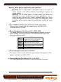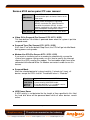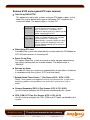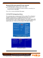
1
Senses 6100 series panel PC user manual
Industrial Panel PCs
Senses 6100 series
Senses 6172 / 6170 / 6152 / 6150LP
User manual
(Issue A)
Part No: 85090083
Page 1 of 90
Amplicon.com
IT and Instrumentation for industry
Sales: +44 (0) 1273 570 220 Website: www.amplicon.com Email: [email protected]
Senses 6100 series panel PC user manual
Copyright
Copyright © 2008 Amplicon Liveline Ltd.
All rights reserved. This publication, including all photographs, illustrations
and software, is protected under international copyright laws, with rights
reserved. No part of this manual may be reproduced, copied, translated or
transmitted in any form or by any means without the prior written consent
from Amplicon Liveline Ltd.
Acknowledgements
All product names or trademarks are properties of their respective owners.
Disclaimer
This instruction manual is supplied to provide the user with sufficient
information to utilise the purchased product in a proper and efficient manner.
The information contained has been reviewed and is believed to be accurate
and reliable. However, Amplicon Liveline Ltd accepts no responsibility for any
problems caused by errors and omissions. Specifications and instructions are
subject to change without notice.
The Senses 6100 series industrial panel PCs are RoHS compliant.
Page 2 of 90
Amplicon.com
IT and Instrumentation for industry
Sales: +44 (0) 1273 570 220 Website: www.amplicon.com Email: [email protected]
Senses 6100 series panel PC user manual
Table of Contents
Safety Precautions
5
C h a p t e r 1 - Introduction
7
1.1
1.2
1.2.1
1.2.2
1.2.3
1.3
1.4
1.4.1
1.4.2
1.5
7
8
8
9
10
12
16
16
17
21
General Description
System Specifications
Main CPU Board
I/O System
System Specification
Dimensions
Front View and I/O Outlets
Front View
I/O Outlets
Content List
C h a p t e r 2 - Hardware installation
22
2.1
2.2
2.3
2.4
2.5
2.6
2.6.1
2.6.2
2.7
2.8
2.8.1
2.8.2
2.8.3
2.8.4
22
26
33
34
35
36
36
37
37
38
38
38
39
40
CPU and DRAM Installation
Hard Disk Drive Installation
CD-ROM Installation
Add-on Card Installation
Serial Port Interface
Graphics (DVI-I or VGA)
DVI (For Senses 6172 / 6170 / 6152)
VGA (For Senses 6150LP)
Ethernet
Mounting
Panel Mounting
Wall Mounting
Rack Mounting
VESA Mounting
C h a p t e r 3 - Phoenix-Award BIOS Utility
42
3.1
3.2
3.3
3.4
3.5
3.6
3.7
3.8
3.9
42
43
44
44
45
48
55
58
64
Entering Setup
Control Keys
Getting Help
The Main Menu
Standard CMOS Setup Menu
Advanced BIOS Features
Advanced Chipset Features
Integrated Peripherals
Power Management Setup
Page 3 of 90
Amplicon.com
IT and Instrumentation for industry
Sales: +44 (0) 1273 570 220 Website: www.amplicon.com Email: [email protected]
Senses 6100 series panel PC user manual
3.10
3.11
3.12
3.13
3.14
3.15
3.16
PnP/PCI Configuration Setup
PC Health Status
Frequency/Voltage Control
Load Optimized Defaults
Set Supervisor/User Password
Save & Exit Setup
Exit Without Saving
69
71
72
73
74
76
76
C h a p t e r 4 - Driver installation
78
4.1
4.2
4.2.1
4.2.2
4.2.3
78
79
79
79
82
System
Touchscreen
Specification
Driver Installation – Windows 2000/XP/Vista
Driver Installation – DOS
A p p e n d I x - Power Supply Specification
85
A. Power Supply for Senses 6172 / 6170 / 6152
B. Power Supply for Senses 6150LP
85
88
Page 4 of 90
Amplicon.com
IT and Instrumentation for industry
Sales: +44 (0) 1273 570 220 Website: www.amplicon.com Email: [email protected]
Senses 6100 series panel PC user manual
Safety Precautions
• Before you unpack your Panel PC system, ensure you carefully read
through this manual and follow any related safety or operational
instructions.
• Only suitably qualified and experienced personnel should work inside the
computer.
• Before commencing work within the PC ensure that the mains is
disconnected from the PC and any attached peripherals.
Operation of your panel PC
Before operating your panel PC please:
• Read the equipment ratings plate and ensure that the mains circuit is
suitably rated to power the equipment, to avoid risk of overloading. Do not
use mains adaptors, or extenders.
• Ensure that any cables connecting to the equipment are made safe and do
not present a tripping hazard.
• To avoid risk of electric shock ensure that equipment is plugged into a
suitably earthed mains outlet. Only use the power cord supplied with your
panel PC or power supply unit. Do not continue to use the cable if it is cut
or damaged
---• Ensure the Panel PC chassis is kept away from heat sources, such as
radiators and heating vents.
• Panel PC chassis ventilation slots must be kept clear and not blocked.
Failure to do so is likely to cause the unit to overheat and become
unstable.
• Avoid connecting the Panel PC to an electrical supply which may have
unacceptable interruptions, surges, spikes or noise. We recommend the
use of an uninterruptible power supply (UPS), surge protector or mains
conditioner to address the problem.
---• Turn OFF the system power before cleaning. Clean the system using a
cloth only. Do not spray any liquid cleaner directly onto the screen.
Although the touchscreen is chemical resistant, it is recommended that
you spray the liquid cleaner on a cloth first before wiping the screen.
• Avoid using sharp objects to operate the touchscreen. Scratches on the
touchscreen may cause malfunction or internal failure to the touchscreen.
• The flat panel display is susceptible to shock or vibration. When
assembling the Senses 61xx, make sure it is securely installed.
Page 5 of 90
Amplicon.com
IT and Instrumentation for industry
Sales: +44 (0) 1273 570 220 Website: www.amplicon.com Email: [email protected]
Senses 6100 series panel PC user manual
Electrostatic Discharge Damage
• When working on the inside of a panel PC system, you must be aware that
many of the components are electrostatic discharge sensitive (ESD).
These components can easily be damaged if suitable precautions are not
taken. ESD damage is not always immediately apparent and may result in
a failure many weeks later. When working on equipment we recommend
the use of an ESD mat and wrist strap.
Page 6 of 90
Amplicon.com
IT and Instrumentation for industry
Sales: +44 (0) 1273 570 220 Website: www.amplicon.com Email: [email protected]
Senses 6100 series panel PC user manual
Chapter 1
Introduction
This chapter contains general information and detailed specifications of the
Senses 6100 series.
Senses 6172
Senses 6170
Senses 6152
Senses 6150LP
– 17” LCD touchscreen and 2 x PCI expansion slots
– 17” LCD touchscreen and slim chassis design
– 15” LCD touchscreen and 2 x PCI expansion slots
– 15” LCD touchscreen, slim chassis design
and low power consumption
Chapter 1 includes the following sections:
• General Description
• System Specification
• Dimensions
• Front View & I/O Outlets
• Package List
1.1 General Description
The Senses 6100 series comprises a TFT Touch Panel PC, equipped with
Intel Core 2 Duo processors (or Mobile processors for low power
applications) and 17” SXGA or 15” XGA touchscreen LCD. These industrial
panel PCs are complete full-function and cost-effective industrial HMI
controllers.
Powerful computing via Intel Core 2 Duo processors
The Senses 6172 / 6170 / 6152 panel PCs feature Intel Core 2 Duo
processors and Intel Q965 + ICH8 chipset to provide powerful computing
performance. The Senses 6150LP panel PC features an Intel Core Duo
Mobile processor and Intel 945GM + ICH7M chipset to provide powerful
computing performance and low power (LP) consumption.
With dual 1394a ports, dual Gigabit Ethernet ports and up to 4GB of dualchannel DDR2 system memory, these panel PCs can deliver high computing
capability for high performance and demanding applications.
Page 7 of 90
Amplicon.com
IT and Instrumentation for industry
Sales: +44 (0) 1273 570 220 Website: www.amplicon.com Email: [email protected]
Senses 6100 series panel PC user manual
Expandable for 2 PCI slots
The Senses 6172 / 6152 have 2 x PCI slots for expansion purposes. These
slots are commonly used for standard half-size PCI cards.
Slim designed panel PCs
The Senses 6170 / 6150LP have a slim chassis design making them ideal for
wall mount or VESA mount applications.
Speaker & WLAN antenna supported
The Senses 6172 / 6152 feature built-in speakers. All models feature optional
WLAN module and antenna for wireless network connectivity.
These industrial-grade panel PCs are suited to industrial or commercial
market applications, such as transportation, factory automation, HMI machine
controller, Point Of Sale, KIOSK and more. They provide highly reliable and
flexible industrial-grade all-in-one solutions.
1.2 System Specifications
1.2.1 Main CPU Board
• CPU
o Socket LGA775 for Intel Core 2 Duo / Core Solo / Pentium 4
Processors with FSB 533/800/1066 MHz (for Senses 6172 / 6170 /
6152)
o Socket M (478-pin) for Intel Core 2 Duo M / Core Duo M / Core Solo
M / Celeron M Processors with 533/667MHz (for Senses 6150LP)
• System Chipset
o Intel Q965 + ICH8 (for Senses 6172 / 6170 / 6152)
o Intel 945GM + ICH7M (for Senses 6150LP)
• BIOS
o Phoenix-Award BIOS, 4Mbit with RPL/PXE LAN Boot ROM,
SmartView and Customer CMOS Backup
• System Memory
o 2 x 240-pin DDR2 DIMM maximum up to 4GB (note that
physical available memory may be limited by operating system)
• L2 Cache
o Integrated in CPU
• Bus Clock
o 533/800/1066 MHz (for Senses 6172 / 6170 / 6152)
o 533/667MHz (for Senses 6150LP)
Page 8 of 90
Amplicon.com
IT and Instrumentation for industry
Sales: +44 (0) 1273 570 220 Website: www.amplicon.com Email: [email protected]
Senses 6100 series panel PC user manual
• Watchdog Timer
o Up to 255 levels as Reset feature
1.2.2 I/O System
• Standard I/O
o 3 x serial ports with power
(2 x RS-232 (COM2, COM3), 1 x RS-232/422/485 (COM1))
o 1 x PS/2 for Keyboard + Mouse interface
(for Senses 6172 / 6170 / 6152)
o 2 x PS/2 for Keyboard + Mouse interface
(for Senses 6150LP)
o 4 x USB 2.0 ports
o 2 x IEEE1394a Ports
o 1 x DVI-I Output (for Senses 6172 / 6170 / 6152)
o 1 x VGA
(for Senses 6150LP)
• Ethernet
o First port with i82566DM Gigabit Ethernet PHY,
Second port with RTL8111B for Gigabit/Fast Ethernet
(for Senses 6172 / 6170 / 6152)
o Dual RL 8111B for PCI-E Gigabit Ethernet
(for Senses 6150LP)
• Audio
o HD Audio for two channel output
(for Senses 6172 / 6170 / 6152)
o Realtek AC’97 codec audio (for Senses 6150LP)
o MIC-In, Line-Out
• Storage
o 4 x SATA-300 interface (for Senses 6172 / 6170 / 6152)
o 1 x PATA-100 IDE, 2 x SATA-150 (for Senses 6150LP)
o All Senses 6100 panel PCs come with a 3.5” 250GB SATA HDD
as standard
• Expansion Slot
o 2 x 32-bit PCI Master slots (for Senses 6172 / 6152)
• Optical drive
o 1 x built-in slim CDROM drive (for Senses 6172 / 6152)
Page 9 of 90
Amplicon.com
IT and Instrumentation for industry
Sales: +44 (0) 1273 570 220 Website: www.amplicon.com Email: [email protected]
Senses 6100 series panel PC user manual
1.2.3 System Specification
• Display
o 17.0” SXGA TFT LCD with resistive touchscreen
(for Senses 6172 / 6170)
o 15.0” XGA TFT LCD with resistive touchscreen
(for Senses 6152 / 6150LP)
• Disk Drive Housing
o 1 x internal 3.5” SATA hard drive (as standard)
(2 x 2.5” hard drive or solid state drive on request)
• AC Power Supply (100V ~ 240V)
• Power rating
o 250W (for Senses 6172 / 6170 / 6152)
o 180W (for Senses 6150LP)
• Heat Dispensing Design
• Gross Weight
o Approx 15kg (for Senses 6172 / 6152)
o Approx 10kg (for Senses 6170 / 6150LP)
• Dimensions
o Panel: 450(W) x 370(H) x 12(D) mm (for Senses 6172)
o Case: 415(W) x 339(H) x 138(D) mm (for Senses 6172)
o Panel: 450(W) x 370(H) x 12(D) mm (for Senses 6170)
o Case: 415(W) x 339(H) x 75(D) mm (for Senses 6170)
o Panel: 420(W) x 335(H) x 12(D) mm (for Senses 6152)
o Case: 380(W) x 310(H) x 138(D) mm (for Senses 6152)
o Panel: 420(W) x 335(H) x 12(D) mm (for Senses 6150LP)
o Case: 380(W) x 310(H) x 75(D) mm (for Senses 6150LP)
• Operating Temperature
o 5 to 40°C @ 50% relative humidity
• Relative Humidity
o 10% to 85% @ 40℃, Non-Condensing
• Altitude
o 10,000 ft. (3,000 meters)
• Vibration (Operating)
o 5 to 500 Hz, 1 G random
Page 10 of 90
Amplicon.com
IT and Instrumentation for industry
Sales: +44 (0) 1273 570 220 Website: www.amplicon.com Email: [email protected]
Senses 6100 series panel PC user manual
• Shock (Operating)
o 10 G peak acceleration (11 msec. duration)
NOTE All specifications and images are subject to change without
notice.
Page 11 of 90
Amplicon.com
IT and Instrumentation for industry
Sales: +44 (0) 1273 570 220 Website: www.amplicon.com Email: [email protected]
Senses 6100 series panel PC user manual
1.3 Dimensions
The following diagrams show the dimensions and outlines of Senses 6100
series panel PCs.
• Senses 6172 dimensions
Page 12 of 90
Amplicon.com
IT and Instrumentation for industry
Sales: +44 (0) 1273 570 220 Website: www.amplicon.com Email: [email protected]
Senses 6100 series panel PC user manual
• Senses 6170 dimensions
Page 13 of 90
Amplicon.com
IT and Instrumentation for industry
Sales: +44 (0) 1273 570 220 Website: www.amplicon.com Email: [email protected]
Senses 6100 series panel PC user manual
• Senses 6152 dimensions
Page 14 of 90
Amplicon.com
IT and Instrumentation for industry
Sales: +44 (0) 1273 570 220 Website: www.amplicon.com Email: [email protected]
Senses 6100 series panel PC user manual
• Senses 6150LP dimensions
Page 15 of 90
Amplicon.com
IT and Instrumentation for industry
Sales: +44 (0) 1273 570 220 Website: www.amplicon.com Email: [email protected]
Senses 6100 series panel PC user manual
1.4 Front view and I/O outlets
1.4.1 Front view
Please refer to the following illustration for features and controls of the
Senses 6100 series panel PC front bezels.
No
Function
1
SEL+
2
SEL-
3
Backlight ON/OFF
Page 16 of 90
Amplicon.com
IT and Instrumentation for industry
Sales: +44 (0) 1273 570 220 Website: www.amplicon.com Email: [email protected]
Senses 6100 series panel PC user manual
1.4.2 I/O outlets
The following figures show the I/O locations of the Senses 6100 series panel
PCs.
• Senses 6172 I/O outlets
No
Connector
No
Connector
1
COM1
(RS-232/422/485)
7
COM 2 & COM 3
(RS-232)
2
DVI-I
8
Power Switch
3
Giga LAN x 2
9
AC power
4
IEEE 1394a x 2
10 PCI slots x 2
5
USB v2.0 x 4
11
6
Mic-in, Line-Out
PS/2
Keyboard/Mouse
Page 17 of 90
Amplicon.com
IT and Instrumentation for industry
Sales: +44 (0) 1273 570 220 Website: www.amplicon.com Email: [email protected]
Senses 6100 series panel PC user manual
• Senses 6170 I/O outlets
No
Connector
No
Connector
1
COM1
(RS-232/422/485)
6
Mic-in, Line-Out
2
DVI-I
7
PS/2
Keyboard/Mouse
3
Giga LAN x 2
8
COM 2 & COM 3
(RS-232)
4
IEEE 1394a x 2
9
Power Switch
5
USB v2.0 x 4
10
AC power
Page 18 of 90
Amplicon.com
IT and Instrumentation for industry
Sales: +44 (0) 1273 570 220 Website: www.amplicon.com Email: [email protected]
Senses 6100 series panel PC user manual
• Senses 6152 I/O outlets
No
Connector
No
Connector
1
COM1
(RS-232/422/485)
7
COM 2 & COM 3
(RS-232)
2
DVI-I
8 Power Switch
3
Giga LAN x 2
9 AC power
4
IEEE 1394a x 2
10 PCI slots x 2
5
USB v2.0 x 4
11
6
Mic-in, Line-Out
PS/2
Keyboard/Mouse
Page 19 of 90
Amplicon.com
IT and Instrumentation for industry
Sales: +44 (0) 1273 570 220 Website: www.amplicon.com Email: [email protected]
Senses 6100 series panel PC user manual
• Senses 6150LP I/O outlets
No
Connector
No
Connector
1
IEEE 1394a x 2
5 VGA
2
COM 2 & COM 3
(RS-232)
6 Giga LAN x 2
3
Power switch
7 USB v2.0 x 4
4
PS/2
Keyboard/Mouse
8 Mic-in, Line-Out
Page 20 of 90
Amplicon.com
IT and Instrumentation for industry
Sales: +44 (0) 1273 570 220 Website: www.amplicon.com Email: [email protected]
Senses 6100 series panel PC user manual
1.5 Content List
When you receive the Senses 6100 series panel PC, please find the following
items in the package.
• Senses 61xx panel PC
• AC power cord x 1
• Amplicon product CD x1
• DVI TO VGA Adaptor x 1 (for Senses 6172 / 6170 / 6152)
• PS/2 Splitter – Y Cable x 1 (for Senses 6172 / 6170 / 6152)
• Panel mount kit x 7
• Rack Mount Bracket Kit x 1 (Optional)
• Wall / VESA mount bracket x 1 (Optional) (for Senses 6170 / 6150LP)
• Desktop Kit x 1 (Optional) (for Senses 6170 / 6150LP)
Page 21 of 90
Amplicon.com
IT and Instrumentation for industry
Sales: +44 (0) 1273 570 220 Website: www.amplicon.com Email: [email protected]
Senses 6100 series panel PC user manual
Chapter 2
Hardware installation
The Senses 6100 series provides flexibility for storage drive selection
allowing different configurations such as hard disk drives (HDD), solid state
drives, WLAN cards and PCI cards. This chapter shows how to install
different hardware options. These include:
• CPU
• DRAM
• Hard Disk
• CD-ROM
• Add-On Card
• Serial Port
• VGA
• Ethernet
• Mounting
2.1 CPU and DRAM Installation
The standard Senses 6100 series panel PC is designed for Intel Core 2 Duo
processors (Intel Core 2 Duo Mobile for the Senses 6150LP). The built-in
CPU board provides two 240-pin DDR2 DIMM sockets that support system
memory up to 4GB (note that physical available memory may be limited by
operating system).
Please refer to the instructions below, illustrated with concise images, to
upgrade the CPU and DRAM step by step:
• Step 1
Make sure the panel PC is turned off.
• Step 2
Make sure the AC power-cord is unplugged.
Page 22 of 90
Amplicon.com
IT and Instrumentation for industry
Sales: +44 (0) 1273 570 220 Website: www.amplicon.com Email: [email protected]
Senses 6100 series panel PC user manual
• Step 3
Locate screws on the rear chassis as illustrated, and
unscrew to open it.
(for Senses 6170)
(for Senses 6150LP)
Page 23 of 90
Amplicon.com
IT and Instrumentation for industry
Sales: +44 (0) 1273 570 220 Website: www.amplicon.com Email: [email protected]
Senses 6100 series panel PC user manual
• Step 3
Remove the riser card fixing kit. The CPU and DRAM can
now be installed accordingly.
(for Senses 6172)
(for Senses 6170)
Page 24 of 90
Amplicon.com
IT and Instrumentation for industry
Sales: +44 (0) 1273 570 220 Website: www.amplicon.com Email: [email protected]
Senses 6100 series panel PC user manual
(for Senses 6152)
(for Senses 6150LP)
Page 25 of 90
Amplicon.com
IT and Instrumentation for industry
Sales: +44 (0) 1273 570 220 Website: www.amplicon.com Email: [email protected]
Senses 6100 series panel PC user manual
2.2 HDD installation
The Senses 6100 series offer convenient drive bay modules for users to
install 1 x 3.5” HDDs or 2 x 2.5” HDDs or solid state drives.
Please refer to the instructions below, illustrated with concise images, to
install the hard drive or solid state drive step by step:
• Step 1
Make sure the panel PC is turned off.
• Step 2
Make sure the AC power-cord is unplugged
• Step 3
After removing the rear plate of the panel PC by removing
fastening screws, remove the riser kit (for the Senses 6172 /
6152) and unscrew 4 screws to take out HDD bracket kit
from system in order to install the 3.5” or 2.5” HDD. (HDD
bracket is pre-installed in the panel PC).
(for Senses 6172)
Page 26 of 90
Amplicon.com
IT and Instrumentation for industry
Sales: +44 (0) 1273 570 220 Website: www.amplicon.com Email: [email protected]
Senses 6100 series panel PC user manual
(for Senses 6170)
(for Senses 6152)
(for Senses 6150LP)
Page 27 of 90
Amplicon.com
IT and Instrumentation for industry
Sales: +44 (0) 1273 570 220 Website: www.amplicon.com Email: [email protected]
Senses 6100 series panel PC user manual
• Step 4
Single 3.5” HDD installation is now complete.
• Step 5
If 2.5” HHD is being fitted, then change to 2.5” HDD bracket
as shown below.
Page 28 of 90
Amplicon.com
IT and Instrumentation for industry
Sales: +44 (0) 1273 570 220 Website: www.amplicon.com Email: [email protected]
Senses 6100 series panel PC user manual
• Step 6
Single or dual 2.5” HDD installation is now complete.
• Step 7
For dual 3.5” HDD installation (for Senses 6172 / 6152),
change HDD bracket as shown below. Then Fix the HDD to
the HDD bracket to complete the installation.
Page 29 of 90
Amplicon.com
IT and Instrumentation for industry
Sales: +44 (0) 1273 570 220 Website: www.amplicon.com Email: [email protected]
Senses 6100 series panel PC user manual
• Step 8
When installing Dual 3.5” HDD, users must install a suitable
fan to decrease system heat. Installation step as illustrated
below.
Page 30 of 90
Amplicon.com
IT and Instrumentation for industry
Sales: +44 (0) 1273 570 220 Website: www.amplicon.com Email: [email protected]
Senses 6100 series panel PC user manual
Screw the fan to the right side of cover.
Page 31 of 90
Amplicon.com
IT and Instrumentation for industry
Sales: +44 (0) 1273 570 220 Website: www.amplicon.com Email: [email protected]
Senses 6100 series panel PC user manual
Connect power cable of fan to 3 pin fan connector (CN3) on
the motherboard as shown.
• Step 9
Close rear of the chassis and fasten screws.
Page 32 of 90
Amplicon.com
IT and Instrumentation for industry
Sales: +44 (0) 1273 570 220 Website: www.amplicon.com Email: [email protected]
Senses 6100 series panel PC user manual
2.3 CD-ROM Installation
The Senses 6172 / 6152 offer convenient drive bay modules for users to
install CD-ROM drives. When installing the CD-ROM, refer to the following
instructions and illustrations:
• Step 1
Unscrew screws to remove the rear chassis.
• Step 2
Remove the riser card fix kit.
• Step 3
Unscrew 4 screws which are around the chassis.
(For Senses 6172)
(For Senses 6152)
• Step 4
The CD-ROM can now be taken out.
Page 33 of 90
Amplicon.com
IT and Instrumentation for industry
Sales: +44 (0) 1273 570 220 Website: www.amplicon.com Email: [email protected]
Senses 6100 series panel PC user manual
2.4 Add-on card installation
The Senses 6172 / 6152 provide riser cards for PCI slot expansion. The riser
card assembly can accommodate two half-size expansion cards. To install
the riser card, refer to the following instructions and illustrations below:
• Step 1
Unscrew relevant screws to remove the rear of the chassis.
• Step 2
Remove the riser card fixing kit.
• Step 3
Remove plates.
• Step 4
Insert the add-on card in the socket firmly until it is
completely secured.
(For Senses 6172)
Page 34 of 90
Amplicon.com
IT and Instrumentation for industry
Sales: +44 (0) 1273 570 220 Website: www.amplicon.com Email: [email protected]
Senses 6100 series panel PC user manual
(For Senses 6152)
Step 5
Replace the rear of the chassis. Installation is now
complete.
2.5 Serial Port Interface
The Senses 6100 series panel PCs have four onboard serial ports, COM1
(RS-232/485/422 selectable), COM2 (RS-232), COM3 (RS-232), COM4 (RS232 used for touchscreen).
COM1, COM2 and COM3 have DB-9 connectors and the following table
shows the pin assignments of the connector.
Pin
Signal
Pin
1
DCD, Data
Carrier Detect
6
2
RXD, Receive
Data
7
3
TXD, Transmit
Data
8
4
DTR, Data
Terminal Ready
9
5
GND, Ground
Signal
DSR, Data
Set Ready
RTS,
Request To
Send
CTS, Clear
To Send
RI/+5V/+12
V Ring
Indicator
Page 35 of 90
Amplicon.com
IT and Instrumentation for industry
Sales: +44 (0) 1273 570 220 Website: www.amplicon.com Email: [email protected]
Senses 6100 series panel PC user manual
2.6 Graphics (DVI-I or VGA)
The Senses 6172 / 6170 / 6152 have DVI-I interface connectors with DVIVGA adaptors while the Senses 6150LP has a VGA connector. The DVI-I
interface is able to connect to an expansion CRT monitor, and the system can
display on both the flat panel and the CRT simultaneously.
2.6.1 DVI (For Senses 6172 / 6170 / 6152)
Pin
Signal
1
3
5
7
9
11
13
15
17
19
Pin
Signal
2
4
6
8
10
12
14
16
18
20
TX2Ground
CRT_SPD DATA
DVI_SPD DATA
TX1Ground
NC
Ground
TX0Ground
Pin
Signal
TX2+
CRT_SPD_CLK
DVI_SPD_CLK
CRT-VSYNC
TX1+
NC
VGAVCC
FPDETECT
TX0+
NC
Pin
Signal
21
23
C1
C3
C5
22
24
C2
C4
NC
TXC+
CRT-RED
CRT-BLUE
VGAGND
Ground
TXCCRT-GREEN
CRT-HSYNC
NOTE It doesn’t support display in LCD and DVI-D simultaneously. DVID is only available after booting up in Windows XP.
Page 36 of 90
Amplicon.com
IT and Instrumentation for industry
Sales: +44 (0) 1273 570 220 Website: www.amplicon.com Email: [email protected]
Senses 6100 series panel PC user manual
2.6.2 VGA (For Senses 6150LP)
The Senses 6150LP has an analogue RGB interface connector. It is able to
connect to an expansion CRT monitor, and the system can display on both
the flat panel and the CRT simultaneously.
2.7 Ethernet
The Senses 6100 series panel PCs provide dual NE2000 compatible
Ethernet (RJ-45) interfaces. For network connection, just plug in one cable
end of the system’s 10/100/1000-Base-T Hub into a standard RJ-45
connector. Please refer to detailed pin assignment list below:
Pin
Signal
1
TX+ (Data transmission positive
2
TX- (Data transmission negative)
3
Rx+(Data reception positive)
4
5
6
RJ45 termination
RJ45 termination
Rx- (Data reception negative)
7
8
RJ45 termination
RJ45 termination
1 2 3 4 5 6 7 8
RJ-45
Page 37 of 90
Amplicon.com
IT and Instrumentation for industry
Sales: +44 (0) 1273 570 220 Website: www.amplicon.com Email: [email protected]
Senses 6100 series panel PC user manual
2.8 Mounting
There are several mounting methods available for the Senses 6100 series
panel PCs. These are listed below.
2.8.1 Panel Mounting
All Senses 6100 panel PCs are designed for panel mount applications. To
panel mount one of these, the standard mounting kit (included in the system
packaging) is needed.
2.8.2 Wall Mounting
The Senses 6170 / 6150LP are suited to wall mounting applications. The wall
mounting kit is optional. Please refer to the illustrations for mounting
instructions.
• Step 1 Use 6 screws to fix the wall mounting bracket to the rear of the
panel PC.
Page 38 of 90
Amplicon.com
IT and Instrumentation for industry
Sales: +44 (0) 1273 570 220 Website: www.amplicon.com Email: [email protected]
Senses 6100 series panel PC user manual
• Step 2 Complete the wall mount installation.
2.8.3 Rack Mounting
All Senses 6100 panel PCs are suited to rackmount applications. The rack
mounting kit is optional. Please refer to the following for installation
instructions.
• Step 1 Attach the rackmount brackets by fixing 5 screws to each side of
the panel PC.
Page 39 of 90
Amplicon.com
IT and Instrumentation for industry
Sales: +44 (0) 1273 570 220 Website: www.amplicon.com Email: [email protected]
Senses 6100 series panel PC user manual
• Step 2 Complete the rackmount installation.
2.8.4 VESA Mounting
The Senses 6170 / 6150LP are suited to VESA mount applications. These
include 75 x 75 mm and 100 x 100 mm VESA mount. The VESA mount
bracket is the same as the wall mount bracket. Please refer to the following
steps for installation instructions.
• Step 1 Assemble wall / VESA mount bracket.
Page 40 of 90
Amplicon.com
IT and Instrumentation for industry
Sales: +44 (0) 1273 570 220 Website: www.amplicon.com Email: [email protected]
Senses 6100 series panel PC user manual
• Step 2 Fix the VESA arm to complete installation.
Page 41 of 90
Amplicon.com
IT and Instrumentation for industry
Sales: +44 (0) 1273 570 220 Website: www.amplicon.com Email: [email protected]
Senses 6100 series panel PC user manual
Chapter 3
Phoenix-Award BIOS Utility
The Phoenix-Award BIOS provides users with a built-in Setup program to
modify basic system configuration. All configured parameters are stored in a
battery-backed-up RAM (CMOS RAM) to save the Setup information
whenever the power is turned off.
3.1 Entering Setup
There are two ways to enter the Setup program. You may either turn ON the
computer and press <Del> immediately, or press the <Del> and/or <Ctrl>,
<Alt>, and <Esc> keys simultaneously when the following message appears
at the bottom of the screen during POST (Power on Self Test).
TO ENTER SETUP PRESS DEL KEY
If the message disappears before you respond and you still want to enter
Setup, please restart the system to try it again. Turning the system power
OFF and ON, pressing the “RESET” button on the system case or
simultaneously pressing <Ctrl>, <Alt>, and <Del> keys can restart the
system. If you do not press keys at the right time and the system doesn’t
boot, an error message will be displayed as follows:
PRESS <F1> TO CONTINUE, <CTRL-ALT-ESC> OR <DEL> TO ENTER
SETUP
Page 42 of 90
Amplicon.com
IT and Instrumentation for industry
Sales: +44 (0) 1273 570 220 Website: www.amplicon.com Email: [email protected]
Senses 6100 series panel PC user manual
3.2 Control Keys
Up arrow
Down arrow
Left arrow
Right arrow
Esc key
PgUp/“+”
key
PgDn/“−
−“
key
F1 key
(Shift) F2
key
F3 key
F4 key
F5 key
F6 key
F7 key
F8 key
F9 key
F10 key
Move cursor to the previous item
Move cursor to the next item
Move cursor to the item on the left hand
Move to the item on the right hand
Main Menu -- Quit and delete changes
into CMOS
Status Page Setup Menu and Option
Page Setup Menu -- Exit current page
and return to Main Menu
Increase the numeric value or make
changes
Decrease the numeric value or make
changes
General help, only for Status Page
Setup Menu and Option Page Setup
Menu
Change color from total 16 colors. F2 to
select color forward, (Shift) F2 to select
color backward
Reserved
Reserved
Restore the previous CMOS value from
CMOS, only for Option Page Setup
Menu
Load the default CMOS value from BIOS
default table, only for Option Page Setup
Menu
Load the Setup default, only for Option
Page Setup Menu
Reserved
Reserved
Save all the CMOS changes, only for
Main Menu
Page 43 of 90
Amplicon.com
IT and Instrumentation for industry
Sales: +44 (0) 1273 570 220 Website: www.amplicon.com Email: [email protected]
Senses 6100 series panel PC user manual
3.3 Getting Help
Main Menu
The online description of the highlighted setup function is displayed at the
bottom of the screen.
Status Page Setup Menu/Option Page Setup Menu
Press <F1> to display a small Help window that provides the description of
using appropriate keys and possible selections for highlighted items. Press
<F1> or <Esc> to exit the Help Window.
3.4 The Main Menu
Once you enter the Award BIOS CMOS Setup Utility, the Main Menu appears
on the screen. In the Main Menu, there are several Setup functions and a
couple of Exit options for your selection. Use arrow keys to select the Setup
Page you intend to configure then press <Enter> to accept or enter its submenu.
(For Senses 6172 / 6170 / 6152)
Page 44 of 90
Amplicon.com
IT and Instrumentation for industry
Sales: +44 (0) 1273 570 220 Website: www.amplicon.com Email: [email protected]
Senses 6100 series panel PC user manual
(For Senses 6150LP)
NOTE: If your computer will not boot after making and saving system
changes with Setup, the Award BIOS will reset your system to the
CMOS default settings via its built-in override feature.
It is strongly recommended that you should avoid changing the chipset’s
defaults. Both Award and your system manufacturer have carefully set up
these defaults that provide the best performance and reliability.
3.5 Standard CMOS Setup Menu
The Standard CMOS Setup Menu displays basic information about your
system. Use arrow keys to highlight each item, and use the <PgUp> or
<PgDn> keys to select the value you want in each item.
Page 45 of 90
Amplicon.com
IT and Instrumentation for industry
Sales: +44 (0) 1273 570 220 Website: www.amplicon.com Email: [email protected]
Senses 6100 series panel PC user manual
(For Senses 6172 / 6170 / 6152)
(For Senses 6150LP)
Date
The date format is <day>, <date> <month> <year>. Press <F3> to show
the calendar.
day
date
month
year
It is determined by the BIOS and read
only, from Sunday to Saturday.
It can be keyed with the numerical/
function key, from 1 to 31.
It is from January to December.
It shows the current year of BIOS.
Page 46 of 90
Amplicon.com
IT and Instrumentation for industry
Sales: +44 (0) 1273 570 220 Website: www.amplicon.com Email: [email protected]
Senses 6100 series panel PC user manual
Time
This item shows current time of your system with the format <hour>
<minute> <second>. The time is calculated based on the 24-hour militarytime clock. For example, 1 p.m. is 13:00:00.
IDE Primary Master/Primary Slave
These items identify the types of each IDE channel installed in the
computer. There are 45 predefined types (Type 1 to Type 45) and 2 user
definable types (Type User) for Enhanced IDE BIOS. Press <PgUp>/<+>
or <PgDn>/<−> to select a numbered hard disk type, or directly type the
number and press <Enter>. Please note that the drive specifications must
match the drive table. The hard disk will not work properly if improper
information is entered. If the hard disk drive type does not match or is not
listed, Type User can be used to manually define the drive type.
If selecting Type User, you will be asked to enter related information in the
following items. Directly key in the information and press <Enter>. This
information should be provided in the documentation from the hard disk
vendor or the system manufacturer.
If the HDD interface controller supports ESDI, select “Type 1”.
If the HDD interface controller supports SCSI, select “None”.
If the HDD interface controller supports CD-ROM, select “None”.
CYLS.
HEADS
PRECO
MP
number of
cylinders
number of
heads
write precom
LANDZO
NE
SECTOR
S
MODE
landing zone
number of
sectors
HDD access
mode
If there is no hard disk drive installed, select NONE and press <Enter>.
• Dive A type/Drive B type (For Senses 6150LP)
The category identifies the types of floppy disk drive A or drive B installed
in the computer.
None
360K, 3.5 in
1.2M, 3.5 in
No floppy drive installed
3.5 inch PC-type standard drive;
360KB Mini ITXcity
3.5 inch AT-type high-density drive;
1.2MB Mini ITXcity
Page 47 of 90
Amplicon.com
IT and Instrumentation for industry
Sales: +44 (0) 1273 570 220 Website: www.amplicon.com Email: [email protected]
Senses 6100 series panel PC user manual
720K, 3.5 in
1.44M, 3.5
in
2.88M, 3.5
in
3.5 inch double-sided drive; 720KB
Mini ITXcity
3.5 inch double-sided drive; 1.44MB
Mini ITXcity
3.5 inch double-sided drive; 2.88MB
Mini ITXcity
Video (For Senses 6172 / 6170 / 6152)
Select the display adapter type for your system.
Halt On
This item determines whether the system will halt or not, if an error is
detected while powering up.
No errors
The system booting will halt on any
errors detected. (default)
All errors
Whenever BIOS detects a non-fatal
error, the system will stop and you will
be prompted.
The system booting will not stop for a
keyboard error; it will stop for other
errors.
The system booting will not stop for a
disk error; it will stop for other errors.
All, But
Keyboard
All, But
Diskette
All, But
Disk/Key
The system booting will not stop for a
keyboard or disk error; it will stop for
other errors.
Press <Esc> to return to the Main Menu page.
3.6 Advanced BIOS Features
This section allows you to configure and improve your system, by allowing
you to set up system features according to your preference.
Page 48 of 90
Amplicon.com
IT and Instrumentation for industry
Sales: +44 (0) 1273 570 220 Website: www.amplicon.com Email: [email protected]
Senses 6100 series panel PC user manual
(For Senses 6172 / 6170 / 6152)
(For Senses 6150LP)
• CPU Feature
Scroll to this item and press <Enter> to view the CPU Feature sub menu.
Page 49 of 90
Amplicon.com
IT and Instrumentation for industry
Sales: +44 (0) 1273 570 220 Website: www.amplicon.com Email: [email protected]
Senses 6100 series panel PC user manual
(For Senses 6172 / 6170 / 6152)
(For Senses 6150LP)
Hard Disk Boot Priority
Scroll to this item and press <Enter> to view the sub menu to decide the
disk boot priority.
(For Senses 6172 / 6170 / 6152)
Page 50 of 90
Amplicon.com
IT and Instrumentation for industry
Sales: +44 (0) 1273 570 220 Website: www.amplicon.com Email: [email protected]
Senses 6100 series panel PC user manual
(For Senses 6150LP)
Virus Warning (For Senses 6172 / 6170 / 6152)
This option flashes on the screen. During and after the system boot up,
any attempt to write to the boot sector or partition table of the hard disk
drive will halt the system with the following message. You can run an antivirus program to locate the problem. The default setting is “Disabled”.
! WARNING !
Disk boot sector is to be modified
Type “Y” to accept write or “N” to abort write
Award Software, Inc.
Enabled
Disabled
It automatically activates while the system
boots up and a warning message appears
for an attempt to access the boot sector or
hard disk partition table.
No warning message will appear for
attempts to access the boot sector or hard
disk partition table.
NOTE This function is only available with DOS and other operating
systems that do not trap INT13.
CPU L1 & L2 Cache
These two options speed up memory access. However, it depends on the
CPU/chipset design. The default setting is “Enabled”. CPUs with no built-in
internal cache will not provide the “CPU Internal Cache” item on the menu.
Enabled Enable cache
Disabled Disable cache
Hyper-Threading Technology (For Senses 6150LP)
Use this item to enable or disable Hyper-Threading Technology,
Page 51 of 90
Amplicon.com
IT and Instrumentation for industry
Sales: +44 (0) 1273 570 220 Website: www.amplicon.com Email: [email protected]
Senses 6100 series panel PC user manual
which makes a single physical processor perform multi-tasking
function as two logical ones.
Quick Power On Self Test
This option speeds up Power on Self Test (POST) after you turn on the
system power. If set as Enabled, BIOS will shorten or skip some check
items during POST. The default setting is “Enabled”.
Enabled
Disabled
Enable Quick
POST
Normal POST
First/Second/Third Boot Device
These items let you select the 1st, 2nd, and 3rd devices that the system
will search for during its boot-up sequence. Devices include Floppy,
LS120, ZIP100, HDD0~3, SCSI, and CDROM.
Swap Floppy Drive (For Senses 6150LP)
This allows you to determine whether to enable Swap Floppy Drive or not.
When enabled, the BIOS swap floppy drive assignments so that Drive A
becomes Drive B, and Drive B becomes Drive A. By default, this field is set
to Disabled.
Boot Other Device
This item allows the user to enable/disable the boot device not listed on
the First/Second/Third boot devices option above. The default setting is
“Enabled”.
Boot Up Floppy Seek
During POST, BIOS will determine the floppy disk drive type, 40 or 80
tracks. 360KB type is 40 tracks while 720KB, 1.2MB and 1.44MB are all 80
tracks. The default value is “Enabled”.
Enabled
BIOS searches for floppy disk drive to
determine if it is 40 or 80 tracks. Note that
BIOS can not tell from 720KB, 1.2MB or
1.44MB drive type as they are all 80 tracks.
BIOS will not search for the type of floppy
disk drive by track number. There will be no
Disabled
warning message displayed if the drive
installed is 360KB.
Page 52 of 90
Amplicon.com
IT and Instrumentation for industry
Sales: +44 (0) 1273 570 220 Website: www.amplicon.com Email: [email protected]
Senses 6100 series panel PC user manual
Boot Up Num Lock Status
This sets the Num Lock status when the system is powered on.
The default value is “On”.
Gate A20 Option
The default value is “Fast”.
Normal
The A20 signal is controlled by keyboard
controller or chipset hardware.
Fast
Default: Fast. The A20 signal is controlled
by Port 92 or chipset specific method.
Typematic Rate Setting
This item determines the typematic rate of the keyboard. The default value
is “Disabled”.
Enabled
Disabled
Enable typematic rate and typematic
delay programming.
Disable typematic rate and typematic
delay programming. The system BIOS
will use default value of these 2 items,
controlled by keyboard.
Typematic Rate (Chars/Sec)
This option refers to character numbers typed per second by the keyboard.
The default value is “6”.
6
8
10
12
15
20
24
30
6 characters per second
8 characters per second
10 characters per
second
12 characters per
second
15 characters per
second
20 characters per
second
24 characters per
second
30 characters per
second
Typematic Delay (Msec)
This option defines how many milliseconds must elapse before a heldPage 53 of 90
Amplicon.com
IT and Instrumentation for industry
Sales: +44 (0) 1273 570 220 Website: www.amplicon.com Email: [email protected]
Senses 6100 series panel PC user manual
down key begins generating repeat characters. The default value is “250”.
250
500
750
1000
250
msec
500
msec
750
msec
1000
msec
Security Option
This item allows you to limit access to the system and Setup, or just to
Setup. The default value is “Setup”.
System
Setup
If a wrong password is entered at the
prompt, the system will not boot, but the
access to Setup will be denied.
If a wrong password is entered at the
prompt, the system will boot, but the
access to Setup will be denied.
NOTE To disable the security, select PASSWORD SETTING at
Main Menu and then you will be asked to enter a password.
Do not type anything, just press <Enter> and it will disable the
security. Once the security is disabled, the system will boot
and you can enter Setup freely.
APIC Mode
Use this item to enable or disable APIC (Advanced Programmable
Interrupt Controller) mode that provides symmetric multi-processing
(SMP) for systems.
MPS Version Control For OS
This item specifies the version of the Multiprocessor Specification (MPS).
Version 1.4 has extended configuration tables to improve support for
multiple PCI bus configurations and provide future expandability.
Small Logo (EPA) Show (For Senses 6172 / 6170 / 6152)
If enabled, the EPA logo will appear during system booting up; if disabled,
the EPA logo will not appear.
Press <Esc> to return to the Main Menu page.
Page 54 of 90
Amplicon.com
IT and Instrumentation for industry
Sales: +44 (0) 1273 570 220 Website: www.amplicon.com Email: [email protected]
Senses 6100 series panel PC user manual
3.7 Advanced Chipset Features
This section contains previously optimised chipset features on the board, you
are strongly recommended to leave all items on this page at their default
values unless you are very familiar with the technical specifications of your
system hardware.
(For Senses 6172 / 6170 / 6152)
(For Senses 6150LP)
• DRAM Timing Selectable (For Senses 6150LP)
Use this item to increase the timing of the memory. This is related to the
cooling of memory.
Page 55 of 90
Amplicon.com
IT and Instrumentation for industry
Sales: +44 (0) 1273 570 220 Website: www.amplicon.com Email: [email protected]
Senses 6100 series panel PC user manual
• CAS Latency time (For Senses 6150LP)
You can select CAS latency time in HCLKs 2, 3, or Auto. The board
designer should set the values in this field, depending on the DRAM
installed. Do not change the values in this field unless you change
specifications of the installed DRAM or the installed CPU.
System Cacheable BIOS
Selecting Enabled allows caching of the system BIOS ROM at F0000hFFFFFh, resulting in better system performance. However, if any program
writes to this memory area, a system error may result. The default value is
“Disabled”.
Memory Hole At 15M-16M (For Senses 6172 / 6170 / 6152)
You can reserve this area of system memory for ISA adapter ROM. When
this area is reserved, it cannot be cached. The user information of
peripherals that need to use this area of system memory usually discusses
their memory requirements.
• Video BIOS Cacheable (For Senses 6150LP)
This item allows you to change the Video BIOS location from ROM to
RAM. Video Shadow will increase the video speed.
PCI Express Root Port Func
Scroll to this item and press <Enter> to view the sub menu to determine
the PCI Express port.
(For Senses 6172 / 6170 / 6152)
Page 56 of 90
Amplicon.com
IT and Instrumentation for industry
Sales: +44 (0) 1273 570 220 Website: www.amplicon.com Email: [email protected]
Senses 6100 series panel PC user manual
(For Senses 6150LP)
Press <Esc> to return to the Advanced Chipset Features page.
*** VGA Setting ***
PEG/Onchip VGA Control (For Sense 6172 / 6170 / 6152)
Use this item to choose the primary display card.
On-Chip Frame Buffer Size (For Sense 6172 / 6170 / 6152)
Use this item to set the VGA frame buffer size.
DVMT Mode (For Sense 6172 / 6170 / 6152)
DVMT (Dynamic Video Memory Technology) helps you select the video
mode.
DVMT/Fixed Memory Size (For Sense 6172 / 6170 / 6152)
DVMT (Dynamic Video Memory Technology) allows you to select a
maximum size of dynamic amount usage of the video memory. The
system will configure the video memory dependent on your application.
Boot Display (For Sense 6172 / 6170 / 6152)
This item is for Intel define ADD card only.
Press <Esc> to return to the Main Menu page.
Page 57 of 90
Amplicon.com
IT and Instrumentation for industry
Sales: +44 (0) 1273 570 220 Website: www.amplicon.com Email: [email protected]
Senses 6100 series panel PC user manual
3.8 Integrated Peripherals
This section allows you to configure your SuperIO Device, IDE Function and
Onboard Device.
(For Senses 6172 / 6170 / 6152)
(For Senses 6150LP)
OnChip IDE Device
Scroll to this item and press <Enter> to view the sub menu OnChip
IDE Device.
Page 58 of 90
Amplicon.com
IT and Instrumentation for industry
Sales: +44 (0) 1273 570 220 Website: www.amplicon.com Email: [email protected]
Senses 6100 series panel PC user manual
(For Senses 6172 / 6170 / 6152)
(For Senses 6150LP)
IDE HDD Block Mode
Block mode is also called block transfer, multiple commands, or
multiple sector read/write. If your IDE hard drive supports block
mode (most new drives do), select Enabled for automatic detection
of the optimal number of block read/writes per sector the drive can
support.
IDE DMA transfer access
Automatic data transfer between system memory and IDE device
with minimum CPU intervention. This improves data throughput and
frees the CPU to perform other tasks.
Page 59 of 90
Amplicon.com
IT and Instrumentation for industry
Sales: +44 (0) 1273 570 220 Website: www.amplicon.com Email: [email protected]
Senses 6100 series panel PC user manual
On-Chip Primary / Secondary PCI IDE
The integrated peripheral controller contains an IDE interface with
support for two IDE channels. Select Enabled to activate each
channel separately. The default value is “Enabled”.
NOTE Choosing Disabled for these options will automatically
remove the IDE Primary Master / Slave PIO and/or IDE
Secondary Master / Slave PIO items on the menu.
IDE Master / Slave PIO
The four IDE PIO (Programmed Input/Output) fields let you set a PIO
mode (0-4) for each of the four IDE devices that the onboard IDE
interface supports. Modes 0 to 4 provide successively increased
performance. In Auto mode, the system automatically determines the
best mode for each device.
IDE Master/Slave UDMA
Select the mode of operation for the IDE drive. Ultra DMA33/66/100/133 implementation is possible only if your IDE hard drive
supports it and the operating environment
includes a DMA driver. If your hard drive and your system software
both support Ultra DMA-33/66/100/133, select Auto to enable UDMA
mode by BIOS.
SATA Mode (For Senses 6172 / 6170 / 6152)
These options are for you to set up SATA mode: IDE, RAID or AHCI.
NOTE ICH8DO supports Advanced Host Controller Interface
(AHCI) under Microsoft Windows VISTA and Microsoft
Windows XP. ICH8 only supports AHCI under Microsoft
Windows VISTA. These panel PCs use ICH8 and do not
have onboard RAID support function.
LEGACY Mode Support (For Senses 6172 / 6170 / 6152)
Legacy mode support allows devices to function in an operating
environment that is not USB-aware.
Press <Esc> to return to the Integrated Peripherals page.
• Onboard Device (For Senses 6150LP)
Scroll to this item and press <Enter> to view the sub menu Onboard
Device.
Page 60 of 90
Amplicon.com
IT and Instrumentation for industry
Sales: +44 (0) 1273 570 220 Website: www.amplicon.com Email: [email protected]
Senses 6100 series panel PC user manual
(For Senses 6150LP)
USB Controller
Enable this item if you are using the USB in the system. You should
disable this item if a higher-level controller is added.
USB 2.0 Controller
Enable this item if you are using the EHCI (USB2.0) controller in the
system.
USB Keyboard Support
Enable this item if the system has a Universal Serial Bus (USB)
controller, and you have a USB keyboard.
AC’97 Audio Select
Use this item to enable or disable the onboard AC’97 Audio function.
Press <Esc> to return to the Integrated Peripherals page.
• Super IO Device
Scroll to this item and press <Enter> to view the sub menu Super IO
Device.
Page 61 of 90
Amplicon.com
IT and Instrumentation for industry
Sales: +44 (0) 1273 570 220 Website: www.amplicon.com Email: [email protected]
Senses 6100 series panel PC user manual
(For Senses 6172 / 6170 / 6152)
(For Senses 6150LP)
Onboard FDC Controller
Select Enabled if your system has a floppy disk controller (FDC)
installed on the system board and you wish to use it. If you install andin FDC or the system has no floppy drive, select Disabled in this field.
The options available are Enabled, Disabled.
Onboard Serial Port 1/2/3/4
Select an address and corresponding interrupt for the serial port.
Options: 3F8/IRQ4, 2E8/IRQ3, 3E8/IRQ4, 2F8/IRQ3, Disabled, Auto.
Serial Port 1/2/3/4 Use IRQ (For Senses 6172 / 6170 / 6152)
These items assign which I/O address to access onboard serial port
1/2/3/4.
Page 62 of 90
Amplicon.com
IT and Instrumentation for industry
Sales: +44 (0) 1273 570 220 Website: www.amplicon.com Email: [email protected]
Senses 6100 series panel PC user manual
Onboard Paralellel Port
This item allows you to determine access onboard parallel port
controller with which I/O address. The options available are
378H/IRQ7, 278H/IRQ5, 3BC/IRQ7, Disabled. The 3BC option does
not support any EPP modes.
Parallel Port Mode
Select an operating mode for the onboard parallel (printer) port.
Select Normal unless your hardware and software require one of the
other modes offered in this field. The options available are EPP1.9,
ECP, SPP, ECPEPP1.7, EPP1.7.
EPP Mode Select (For Senses 6150LP)
Select EPP port type 1.7 or 1.9.
ECP Mode Use DMA
Select a DMA channel for the parallel port for use during ECP mode.
PWRON After PWR-Fail
This item enables your computer to automatically restart or return to
its operating status.
Press <Esc> to return to the Integrated Peripherals page.
Onboard Lan1/Lan2 Boot ROM (For Senses 6172 / 6170 / 6152)
Use this item to enable or disable the Boot ROM function of the onboard
LAN1/LAN2 chips when the system boots up.
USB Device Setting (For Senses 6172 / 6170 / 6152)
Scroll to this item and press <Enter> to view the sub menu USB Device
Setting. USB (CN16) will not work when USB2.0 Controller is disabled.
Page 63 of 90
Amplicon.com
IT and Instrumentation for industry
Sales: +44 (0) 1273 570 220 Website: www.amplicon.com Email: [email protected]
Senses 6100 series panel PC user manual
(For Senses 6172 / 6170 / 6152)
Press <Esc> twice to return to the Main Menu page.
3.9 Power Management Setup
The Power Management Setup allows you to save energy effectively. It will
shut down the hard disk and turn OFF the video display after a period of
inactivity.
(For Senses 6172 / 6170 / 6152)
Page 64 of 90
Amplicon.com
IT and Instrumentation for industry
Sales: +44 (0) 1273 570 220 Website: www.amplicon.com Email: [email protected]
Senses 6100 series panel PC user manual
(For Senses 6172 / 6170 / 6152)
(For Senses 6150LP)
ACPI Function
This item allows you to enable/disable the Advanced Configuration and
Power Management (ACPI). The function is always “Enabled”.
ACPI Suspend Type
This item specifies the power saving modes for ACPI function. If your
operating system supports ACPI, such as Windows 98SE, Windows ME
and Windows 2000, you can choose to enter the Standby mode in S1
(POS) or S3 (STR) fashion through the setting of this field. Options are:
Page 65 of 90
Amplicon.com
IT and Instrumentation for industry
Sales: +44 (0) 1273 570 220 Website: www.amplicon.com Email: [email protected]
Senses 6100 series panel PC user manual
[S1(POS)] The S1 sleep mode is a low power state. In this state, no
system context is lost (CPU or chipset) and hardware maintains all
system context.
[S3(STR)] The S3 sleep mode is a lower power state where the
information of system configuration and open applications / files is
saved to main memory that remains powered while most other
hardware components turn off to save energy. The information stored
in memory will be used to restore the system when a “wake up” event
occurs.
Run VGABIOS if S3 Resume (For Senses 6172 / 6170 / 6152)
When this item is set to Auto, the system will run VGA BIOS if it is
resumed from the S3 state.
Power Management (For Senses 6172 / 6170 / 6152)
This option allows you to select the type (or degree) of power saving for
Doze, Standby, and Suspend modes. The table below describes each
power management mode:
It is maximum power savings, only
available for SL CPUs. The inactivity
period is 1 minute in each mode.
User
It sets each mode. Select time-out
Define
periods in the PM Timers section.
It is minimum power savings. The
Min
inactivity period is 1 hour in each mode
Saving
(except the hard drive).
Disabled Default value
Max
Saving
Power Management (For Senses 6150LP)
This option allows you to select the type of power Management. The
options available are APM, ACPI.
Video Off Method (For Senses 6172 / 6170 / 6152)
This setting determines the manner in which the monitor is blanked.
Page 66 of 90
Amplicon.com
IT and Instrumentation for industry
Sales: +44 (0) 1273 570 220 Website: www.amplicon.com Email: [email protected]
Senses 6100 series panel PC user manual
V/H
SYNC+Blank
DPMS
Blank Screen
Video Off In Suspend (For Senses 6172 / 6170 / 6152)
This item defines if the video is powered down when the system is put into
suspend mode.
Suspend Type (For Senses 6172 / 6170 / 6152)
If this item is set to the default Stop Grant, the CPU will go into Idle Mode
during power saving mode.
Modem Use IRQ (For Senses 6172 / 6170 / 6152)
If you want an incoming call on a modem to automatically resume the
system from a power-saving mode, use this item to specify the interrupt
request line (IRQ) used by the modem. The fax/modem might have to be
connected to the board Wake On Modem connector in order to use this
feature.
Suspend Mode
After the selected period of system inactivity (1 minute to 1 hour), all
devices except the CPU shut off. The default value is “Disabled”.
Disabled
1/2/4/6/8/10
/20/30/40
Min/1 Hr
Turns OFF vertical and horizontal
synchronization ports and writes blanks to the
video buffer
Select this option if your monitor supports the
Display Power Management Signalling
(DPMS) standard of the Video Electronics
Standards Association (VESA). Use the
software supplied for your video subsystem to
select video power management values.
System only writes blanks to the video buffer.
System will never enter SUSPEND mode
Defines the continuous idle time before the
system entering SUSPEND mode.
If any item defined in (J) is enabled & active,
SUSPEND timer will be reloaded
HDD Power Down
If HDD activity is not detected for the length of time specified in this field,
the hard disk drive will be powered down while all other devices remain
active.
Page 67 of 90
Amplicon.com
IT and Instrumentation for industry
Sales: +44 (0) 1273 570 220 Website: www.amplicon.com Email: [email protected]
Senses 6100 series panel PC user manual
Soft-Off by PWR-BTTN
This option only works with systems using an ATX power supply. It also
allows the user to define which type of soft power OFF sequence the
system will follow. The default value is “Instant-Off”.
Instant-Off
Delay 4 Sec.
This option follows the conventional manner
systems perform when power is turned
OFF. Instant-Off is a soft power OFF
sequence requiring only the switching of the
power supply button to OFF
Upon turning OFF system from the power
switch, this option will delay the complete
system power OFF sequence by
approximately 4 seconds. Within this delay
period, system will temporarily enter into
Suspend Mode enabling you to restart the
system at once.
Wake-Up by PCI card
If enabled, the system can automatically resume when the PCI Modem or
PCI LAN card receives an incoming call.
Power On by Ring
This option allows the system to resume or wake up upon detecting any
ring signals coming from an installed modem. The default value is
“Enabled”.
Resume by Alarm
If enable this item, the system can automatically resume after a fixed time
in accordance with the system’s RTC (real-time clock).
** Reload Global Timer Events ** (For Senses 6172 / 6170 / 6152)
Global Timer (power management) events can prevent the system from
entering a power saving mode or can wake the system from such a
mode.
Primary/Secondary IDE 0/1 (For Senses 6172 / 6170 / 6152)
Use this item to configure the IDE devices monitored by the system.
FDD, COM, LPT Port (For Senses 6172 / 6170 / 6152)
Use this item to configure the FDD, COM and LPT ports monitored by the
system.
Page 68 of 90
Amplicon.com
IT and Instrumentation for industry
Sales: +44 (0) 1273 570 220 Website: www.amplicon.com Email: [email protected]
Senses 6100 series panel PC user manual
PCI PIRQ[A-D]# (For Senses 6172 / 6170 / 6152)
This item can be used to detect PCI device activities; if no activity, the
system will enter sleep mode.
Press <Esc> to return to the Main Menu page.
3.10 PnP/PCI Configuration Setup
This section describes configuring the PCI bus system. PCI, or Peripheral
Component Interconnect, is a computer bus which allows I/O devices to
operate at speeds nearing the speed the CPU itself uses when
communicating with its own special components. This section covers some
very technical items and it is strongly recommended that only qualified and
experienced users should make any changes to the default settings.
(For Senses 6172 / 6170 / 6152)
(For Senses 6150LP)
Page 69 of 90
Amplicon.com
IT and Instrumentation for industry
Sales: +44 (0) 1273 570 220 Website: www.amplicon.com Email: [email protected]
Senses 6100 series panel PC user manual
• Init Display First (For Senses 6150LP)
This item allows you to decide to active whether PCI Slot or AGP
first. The options available are PCI Slot, AGP.
Reset Configuration Data
Normally, you leave this item Disabled. Select Enabled to reset Extended
System Configuration Data (ESCD) when you exit Setup or if installing a
new add-on causes the system reconfiguration a serious conflict such that
the operating system can not boot. Options: Enabled, Disabled.
Resources Controlled By
The Award Plug and Play BIOS can automatically configure all boot and
Plug and Play-compatible devices. If you select Auto, all interrupt request
(IRQ), DMA assignment, and Used DMA fields disappear, as the BIOS
automatically assigns them. The default value is “Manual”.
IRQ Resources
When resources are controlled manually, assign each system interrupt to
one of the following types in accordance with the type of devices using the
interrupt:
1. Legacy ISA Devices compliant with the original PC AT bus specification,
requiring a specific interrupt (such as IRQ4 for serial port 1).
2. PCI/ISA PnP Devices compliant with the Plug and Play standard,
whether designed for PCI or ISA bus architecture.
The default value is “PCI/ISA PnP”.
PCI/VGA Palette Snoop
Some non-standard VGA display cards may not show colors properly. This
item allows you to set whether MPEG ISA/VESA VGA Cards can work with
PCI/VGA or not. When enabled, a PCI/VGA can work with a MPEG
ISA/VESA VGA card; when disabled, a PCI/VGA cannot work with a
MPEG ISA/VESA Card.
** PCI Express related items **
Maximum Payload Size (For Senses 6172 / 6170 / 6152)
When using DDR SDRAM and Buffer size selection, another consideration
in designing a payload memory is the size of the buffer for data storage.
Maximum Payload Size defines the maximum TLP (Transaction Layer
Packet) data payload size for the device.
Press <Esc> to return to the Main Menu page.
Page 70 of 90
Amplicon.com
IT and Instrumentation for industry
Sales: +44 (0) 1273 570 220 Website: www.amplicon.com Email: [email protected]
Senses 6100 series panel PC user manual
3.11 PC Health Status
This section supports hardware monitoring that lets you monitor those
parameters for critical voltages, temperatures and fan speed of the board.
(For Senses 6172 / 6170 / 6152)
(For Senses 6150LP)
Shutdown Temperature (For Senses 6172 / 6170 / 6152)
This helps you set the maximum temperature the system can reach before
powering down.
Current SYSTEM Temperature (For Senses 6172 / 6170 / 6152)
Shows you the current system temperature.
Page 71 of 90
Amplicon.com
IT and Instrumentation for industry
Sales: +44 (0) 1273 570 220 Website: www.amplicon.com Email: [email protected]
Senses 6100 series panel PC user manual
Current CPU Temperature
These read-only fields show the functions of the hardware thermal sensor
by CPU thermal diode that monitors the chip blocks to ensure a stable
system.
Vcore +3.3V/+5V/+12V/VBAT(V)/5VSB (For Senses 6172 / 6170 / 6152)
Show you the voltage of +3.3V/+5V/+12V.
Press <Esc> to return to the Main Menu page.
3.12 Frequency/Voltage Control
This section is to control the CPU frequency and Supply Voltage, DIMM
OverVoltage and AGP voltage.
(For Senses 6172 / 6170 / 6152)
(For Senses 6150LP)
Page 72 of 90
Amplicon.com
IT and Instrumentation for industry
Sales: +44 (0) 1273 570 220 Website: www.amplicon.com Email: [email protected]
Senses 6100 series panel PC user manual
CPU Clock Ratio (For Senses 6172 / 6170 / 6152)
Use this item to select the CPU’s frequency.
Auto Detect PCI Clk
The enabled item can automatically disable the clock source for a PCI slot
without a module, to reduce EMI (ElectroMagnetic Interference).
Spread Spectrum
If spread spectrum is enabled, EMI (Electromagnetic Interference)
generated by the system can be significantly reduced.
Press <Esc> to return to the Main Menu page.
3.13 Load Optimized Defaults
This option allows you to load the default values to your system configuration.
These default settings are optimal and enable all high performance features.
(For Senses 6172 / 6170 / 6152)
Page 73 of 90
Amplicon.com
IT and Instrumentation for industry
Sales: +44 (0) 1273 570 220 Website: www.amplicon.com Email: [email protected]
Senses 6100 series panel PC user manual
(For Senses 6150LP)
To load SETUP defaults value to CMOS SRAM, enter “Y”. If not, enter “N”.
3.14 Set Supervisor/User Password
You can set either supervisor or user password, or both. The differences
between them are:
(For Senses 6150LP)
(For Senses 6150LP)
Page 74 of 90
Amplicon.com
IT and Instrumentation for industry
Sales: +44 (0) 1273 570 220 Website: www.amplicon.com Email: [email protected]
Senses 6100 series panel PC user manual
1.
2.
Supervisor password: Can enter and change the options of the setup
menus.
User password: Can enter but does not have the right to change the
options of the setup menus.
When you select this function, the following message will appear at the center
of the screen to assist you in creating a password.
ENTER PASSWORD:
Type the password with eight characters at most, and press <Enter>. The
password typed will now clear any previously entered password from CMOS
memory. You will be asked to confirm the password. Type the password
again and press <Enter>. You may also press <Esc> to abort the selection
and not enter a password.
To disable password, just press <Enter> when you are prompted to enter
password. A message will confirm the password being disabled. Once the
password is disabled, the system will boot and you can enter Setup freely.
PASSWORD DISABLED.
When a password is enabled, you have to type it every time you enter Setup.
This prevents any unauthorized person from changing your system
configuration.
Additionally when a password is enabled, you can also require the BIOS to
request a password every time the system reboots. This would prevent
unauthorized use of your computer.
You determine when the password is required within the BIOS Features
Setup Menu and its Security option. If the Security option is set to “System”,
the password is required during boot up and entry into Setup. If set as
“Setup”, prompting will only occur prior to entering Setup.
Page 75 of 90
Amplicon.com
IT and Instrumentation for industry
Sales: +44 (0) 1273 570 220 Website: www.amplicon.com Email: [email protected]
Senses 6100 series panel PC user manual
3.15 Save & Exit Setup
This allows you to determine whether or not to accept the modifications.
Typing “Y” quits the setup utility and saves all changes into the CMOS
memory. Typing “N” brings you back to the Setup utility.
(For Senses 6172 / 6170 / 6152)
(For Senses 6150LP)
3.16 Exit Without Saving
Select this option to exit the Setup utility without saving the changes you have
made in this session. Typing “Y” will quit the Setup utility without saving the
modifications. Typing “N” will return you to the Setup utility.
Page 76 of 90
Amplicon.com
IT and Instrumentation for industry
Sales: +44 (0) 1273 570 220 Website: www.amplicon.com Email: [email protected]
Senses 6100 series panel PC user manual
(For Senses 6172 / 6170 / 6152)
(For Senses 6150LP)
Page 77 of 90
Amplicon.com
IT and Instrumentation for industry
Sales: +44 (0) 1273 570 220 Website: www.amplicon.com Email: [email protected]
Senses 6100 series panel PC user manual
Chapter 4
Driver installation
4.1 System
The Senses 6100 series panel PCs support Windows 2000/XP/Vista. To
facilitate the installation of the system driver, please carefully read the
instructions in this chapter before start installing.
1. Here is the path for the system driver:
Senses6100series\Senses6172\Driver
or Senses6100series\Senses6152\Driver
And Senses6100series\Senses6170\Driver
or Senses6100 series\Senses6150LP\Driver
2. Select all files, follow the installing procedure, and finally press OK.
Page 78 of 90
Amplicon.com
IT and Instrumentation for industry
Sales: +44 (0) 1273 570 220 Website: www.amplicon.com Email: [email protected]
Senses 6100 series panel PC user manual
4.2 Touch Screen
4.2.1 Specification
• For Senses 6172 / 6152
Touch Screen
Touch Screen
Controller
Communications
Baud Rate
Resolution
Mode Selection
Power Input
Power
Consumption
5-wire Analog Resistive type
DMC9000 (10-bit A/D converter inside)
Mechanical Size
Portrait
Others
60(L) x 26(W) x 8.3(H)mm
Support 90o to 270o screen rotation
Touch activate indication LED on board
RS-232
19200 and 9600 baud selection
2048 x 2048
PnP or non-PnP
5V DC
12V: 23mA+ i where (i = v/touch screen sheet R)
5V: 20mA+ i where (i = v/touch screen sheet R)
• For Senses 6170 / 6150LP
Touch Screen
Touch Screen
Controller
Communications
Baud Rate
Resolution
Power Input
Power
Consumption
5-wire Analog Resistive type
DMC9000
Board Size
Portrait
Static Protection
Others
6.0 x 2.0 cm
Support 90o to 270o screen rotation
ESD device option
Touch activate indication LED on board
RS-232
19200 baud rate fixed
1024 x 1024 (10 bit A/D converter inside)
5V to 12V DC
12V: 27mA+ i where (i = v/touch screen sheet R)
5V: 23mA+ i where (i = v/touch screen sheet R)
4.2.2 Driver Installation – Windows 2000/XP/Vista
The Senses 6100 series Panel PCs provide touchscreen drivers that users
can install under Windows 2000/XP/Vista. To facilitate this touch screen
Page 79 of 90
Amplicon.com
IT and Instrumentation for industry
Sales: +44 (0) 1273 570 220 Website: www.amplicon.com Email: [email protected]
Senses 6100 series panel PC user manual
driver installation, users should read the instructions in this chapter carefully
before starting the installation.
1. Insert Driver CD and follow the path to select the
• For Senses 6172 / 6152
“Senses6100series\Senses6172\Driver\Step 5. Touch” or
“Senses6100series\Senses6152\Driver\Step 5. Touch”.
• For Senses 6170 / 6150LP
“Senses6100series\Senses6170\Driver\Step 5. Touch”.
“Senses6100series\Senses6150LP\Driver\Step 5. Touch”.
2. Follow the installation procedure and press OK.
3. Click Start menu and select “PenMount Utilities”, and then a “PenMount
Control Panel” pops out.
Note Please choose COM4 for touch screen installation.
Page 80 of 90
Amplicon.com
IT and Instrumentation for industry
Sales: +44 (0) 1273 570 220 Website: www.amplicon.com Email: [email protected]
Senses 6100 series panel PC user manual
4.
Select the “Standard Calibrate” tab.
Page 81 of 90
Amplicon.com
IT and Instrumentation for industry
Sales: +44 (0) 1273 570 220 Website: www.amplicon.com Email: [email protected]
Senses 6100 series panel PC user manual
5. Calibration:
To adjust the display with touch panel, click “Calibration” and follow the
calibrate point to do calibration; there are five points on screen for
calibration.
6. Press OK.
4.2.3 Driver Installation - DOS
• Using “INSTALL.EXE” Utility to Install PenMount Software Driver
1. Insert Driver CD and select
“Senses 6100series\Senses6172\Driver\Step 5.
Touch\Driver\DOS\Install.exe” or
“Senses 6100series\Senses6152\Driver\Step 5.
Touch\Driver\DOS\Install.exe” or
“Senses6100series\Senses6170\Driver\Step 5.
Touch\Driver\DOS\Setup.exe”
“Senses6100series\Senses6150LP\Driver\Step 5.
Touch\Driver\DOS\Setup.exe”
2. Press ENTER key to install the drivers to drive C or use keyboard to key-in
the hard disc drive that you plan to install the driver.
3. The driver will ask “Do you want to modify your Autoexec.bat to initialize
PenMount? (Y/N)” Suggest you choose “YES” for generating the
initialization instructions in AUTOEXEC.BAT files. Then follow up the
instructions to complete the installation.
Page 82 of 90
Amplicon.com
IT and Instrumentation for industry
Sales: +44 (0) 1273 570 220 Website: www.amplicon.com Email: [email protected]
Senses 6100 series panel PC user manual
• Identify the Communication Port and IRQ Number
1. For the first time installation, or changing PenMount Touch Screen’s COM
port, use PMDETECT (e.g. C:\PENMOUNT\PMDETECT) to check the
COM port and IRQ number. PMDETECT will save the correct data to
PMOUSE.CFG file for further use.
2. The driver detects your communication COM port and IRQ number from
COM1 IRQ4, COM2 IRQ3, COM3…. to COM4 IRQ15. PenMount driver
can find the COM port and IRQ number automatically. The screen will
then show:
PenMount is initialized successfully!!!
Create file “pmouse.cfg”. Success.
PenMount internal settings:
Comm. Port: COM<n> IRQ<n>
1. PMDETECT program is able to skip the IRQ number detection if the
Touchscreen Driver Installation 13 does not need to detect the specified
IRQ number. For example, you do not need to detect IRQ5, and the
command is:
C:\PENMOUNT\PMDETECT -N5
2. If you do not need to detect IRQ5 and IRQ9, the command is:
C:\PENMOUNT\PMDETECT -N5 -N9
• Calibration
1. To adjust the touch screen mapping properly to display screen, use
PM.BAT (C:\PENMOUNT\PM) to do calibration. Choose “1” DO
CALIBRATION (adjust screen mapping).
2. The message pops up to ask if you select the video mode number. Use
keyboard to start the calibration, touch the upper-centre point, then rightcentre point, bottom-centre point and left-centre point in sequence. After
the calibration is done, the data will be shown on the screen, press any
key to continue.
3. After the calibration, you are advised to test the touch screen and display
mapped results by choosing “3” DRAWING TEST under PM.BAT
Page 83 of 90
Amplicon.com
IT and Instrumentation for industry
Sales: +44 (0) 1273 570 220 Website: www.amplicon.com Email: [email protected]
Senses 6100 series panel PC user manual
• Initializing the PenMount Driver
If you don’t have the initialization commands in AUTOEXEC.BAT,
initialize PenMount C:\PENMOUNT\PMINIT) controller before you use the
PenMount Touch Screen. The display will show the initialization
message:
PenMount V7.06 Copyright(c) SALT International Corp.
Test:COM<n> IRQ<n> (<n> is the number after PMDETECT done)
PenMount communication settings: COM<N> IRQ<n> Baud Rate:
<xxxx>
Demonstration
To demonstrate or test touch screen operation, please select “3”
DRAWING TEST in PM.BAT file of the Utility Directory. Drawing will be
shown on the screen. The demonstration program “ICECREAM.EXE” in
the “PENMOUNT” directory can be used too.
Page 84 of 90
Amplicon.com
IT and Instrumentation for industry
Sales: +44 (0) 1273 570 220 Website: www.amplicon.com Email: [email protected]
Senses 6100 series panel PC user manual
Appendix
Power Supply Specification
A.
Power Supply for Senses 6172 / 6170 / 6152
(Power Supply FSP250-50GUB (250W, AC100~240V Input))
A.1 Electrical Requirements
• OUTPUT ELECTRICAL REQUIREMENTS
The power supply will meet all electrical specifications below, over the full
operating temperature range and dynamic load regulation.
• OUTPUT RATING
Output
Nominal
Regulation
1
2
3
4
5
+3.3V
+5V
+12V
-12V
+5VSB
±5%
±5%
±5%
±10%
±5%
Ripple/
Noise
50mV
50mV
120mV
120mV
50mV
Min
Max
0.3A 16.8A
0.3A 12.0 A
1.5A 10.0 A
0.0 A 0.8A
0.0 A 2.0A
Note –12V,+3.3V, +5V,+12V will have the regulation to ±10% when all
load removed.
The +3.3V and +5V total output should not exceed 105W. The +3.3.V, +5V,
and +12V total output should not exceed 230W. The total output for this
subject power supply is 250W.
• LOAD CAPACITY SPECIFICATIONS
The cross regulation defined as follows, the voltage regulation limits DC
include DC Output ripple & noise.
LOAD
Condition_1
Condition_2
Condition_3
Condition_4
Condition_5
Condition_6
Condition_7
Condition_8
+3.3
V
X
0.5A
0.5A
1A
1A
4.5A
12A
17A
+5V
+12V
-12V
+5VSB
X
0.3A
2A
2A
10A
18A
2A
9.7A
X
1A
2A
17A
4A
12A
2A
10.5A
X
0A
0.8A
0.1A
0.1A
0.1A
0A
0.8A
2A
0.1A
0.1A
0.1A
0.1A
0.1A
0.1A
2A
Page 85 of 90
Amplicon.com
IT and Instrumentation for industry
Sales: +44 (0) 1273 570 220 Website: www.amplicon.com Email: [email protected]
Senses 6100 series panel PC user manual
• HOLD-UP TIME (@FULL LOAD)
115V / 60Hz : 17ms. Minimum.
230V / 50Hz : 17ms. Minimum.
• OUTPUT RISE TIME
(10% TO 95% OF FINAL OUTPUT VALUE, @FULL LOAD)
115V-rms or
20ms
+3.3Vdc
230V-rms
Maximum
20ms
+ 5Vdc
Maximum
20ms
+ 12Vdc
Maximum
20ms
+ 5Vsb
Maximum
20ms
- 12Vdc
Maximum
• OVER VOLTAGE PROTECTION
Voltage Source
Protection Point
+3.3V
3.76V – 4.8V
+5V
5.6V – 7.0V
+12V
13.0V – 16.5V
• SHORT CIRCUIT PROTECTION
Output short circuit is defined to be a short circuit load of less than 0.1Ohm.
In the event of an output short circuit condition on +3.3V, +5V or +12V output,
the power supply will shutdown and latch off. The power supply shall return to
normal operation after the short circuit has been removed and the power
switch has been turned off for no more than 2 seconds.
• OVERLOAD PROTECTION
Overload currents defined as a 10A/s fault current ramp starting from full
load, applied to the +3.3V, +5V output, shall not cause that output to exceed
32A before the output voltage drops below 0.5V and is latched off. The +12V
output shall not exceed 20A under the same ramp conditions starting at full
load before it is latched off.
Page 86 of 90
Amplicon.com
IT and Instrumentation for industry
Sales: +44 (0) 1273 570 220 Website: www.amplicon.com Email: [email protected]
Senses 6100 series panel PC user manual
• POWER SIGNAL
POWER GOOD @
115/230V,FULL LOAD
POWER FAIL @115/230V,
FULL LOAD
A.2
Required
Minimum
Efficiency
Required
Minimum
Efficiency
1ms minimum
EFFICIENCY
Loading
A.3
100 –500ms
Voltage
Full
load
Typical
load
Light
load
115V
80%
81%
80%
230V
81%
82%
80%
ENVIRONMENTAL REQUIREMENTS
Operating temperature range:
0°C to 50°C
Storage temperature range:
-20°C to +80°C
Humidity, non-condensing:
5% ~ 95%RH, Non-Condensing
Vibration:
0.25G, 10~250Hz
Shock:
-40G, 11ms for Storage,
-10G, 11ms for operating
A.4 RELIABILITY
The power supply reliability, when calculated by MIL-HDBK;latest
revision, are exceed 100,000 hours with all output at maximum load
and an ambient temperature of 25°C.
A.5
SAFETY
NEMKO EN 60950
TUV EN60950 OR VDE EN60950
UL 60950
CSA 22.2 NO. 60950
IEC 60950
CE
Page 87 of 90
Amplicon.com
IT and Instrumentation for industry
Sales: +44 (0) 1273 570 220 Website: www.amplicon.com Email: [email protected]
Senses 6100 series panel PC user manual
B
Power Supply for Senses 6150LP (180W)
(Power Supply: FSP180-50PLA1 (180W, AC 110~230V Input))
B.1.1 ELECTRICAL REQUIREMENTS
• OUTPUT ELECTRICAL REQUIREMENTS
The power supply will meet all electrical specifications below, over the full
operating temperature range and dynamic load regulation.
• OUTPUT RATING
Output Nominal Regulation Ripple/
Noise
1
+3.3V
±5%
50mV
2
+5V
±5%
50mV
3
+12V
±5%
120mV
4
-12V
±10%
120mV
5
+5VSB
±5%
50mV
Min
Max
0.3A 16.8A
0.3A 12.0 A
1.5A 10.0 A
0.0 A 0.8A
0.0 A 2.0A
※ –12V,+3.3V, +5V,+12V will have the regulation to ±10% when all load is
removed. The +3.3V and +5V total output should not exceed 61W. The
+3.3.V, +5V, and +12V total output should not exceed 160W. The total
output for the power supply is 180W.
• LOAD CAPACITY SPECIFICATIONS
The cross regulation defined as follows, the voltage regulation limits DC
include DC Output ripple & noise.
LOAD
ALL
MAX
+5V
MAX
other
MIN
+3.3V
MAX
other
MIN
STM +3.3V
HHHH 4.5A
+5V
9.0A
+12V
9.0A
-12V
0.8A
12.0 A
1.5A
0.0A
1.5A
0.0A
LHLL
0.3A
HLLL
16.8 A 0.3 A
Page 88 of 90
Amplicon.com
IT and Instrumentation for industry
Sales: +44 (0) 1273 570 220 Website: www.amplicon.com Email: [email protected]
Senses 6100 series panel PC user manual
+12V
MAX
other
MIN
ALL
MIN
LLHL
LLLL
0.3 A
0.3 A
10.0A
0.0A
0.3 A
0.3 A
1.5A
0.0A
• HOLD-UP TIME (@FULL LOAD)
115V / 60Hz : 17 mSec. Minimum.
230V / 50Hz : 17 mSec. Minimum.
• OUTPUT RISE TIME
(10% TO 90% OF FINAL OUTPUT VALUE, @FULL LOAD)
115V-rms or 230V-rms + 5Vdc : 20ms Maximum
• OVER VOLTAGE PROTECTION
+5Vdc output: +5.7Vdc minimum,
+ 6.5Vdc maximum
+12Vdc output: +13.3Vdc minimum, +15.6Vdc maximum
+ 3.3Vdc output: +3.7Vdc minimum, + 4.5Vdc maximum
• SHORT CIRCUIT PROTECTION
Output short circuit is defined to be a short circuit load of less than 0.1 ohm.
In the event of an output short circuit condition on +3.3V, +5V or +12V output,
the power supply will shutdown and latch off. The power supply shall return to
normal operation after the short circuit has been removed and the power
switch has been turned off for no more than 2 seconds.
In the event of an output short circuit condition –12V output, the power supply
will not latch off. The power supply shall return to normal operation as soon
as the short circuit has been removed and the power switch has been turned
off for no more than 2 seconds.
• OVERLOAD PROTECTION
Overload currents defined as a 10A/s fault current ramp starting from full
load, applied to the +3.3V, +5V output, shall not cause that output to exceed
32A before the output voltage drops below 0.5V and is latched off. The +12V
Page 89 of 90
Amplicon.com
IT and Instrumentation for industry
Sales: +44 (0) 1273 570 220 Website: www.amplicon.com Email: [email protected]
Senses 6100 series panel PC user manual
output shall not exceed 20A under the same ramp conditions starting at full
load before it is latched off.
• POWER GOOD SIGNAL
The power good signal is a TTL compatible signal for the purpose of initiating
an orderly star-up procedure under normal input operating conditions. This
signal is asserted (low) until +5Vdc has reached 4.75 volts during power up.
Characteristics:
TTL signal asserted (low state) : less than 0.5V while sinking 10mA.
TTL signal asserted (high state): greater than 4.75V while sourcing 0.5mA.
High state output impedance: less or equal to 1Kohm from output to common.
POWER GOOD @
100 –500ms.
115/230V,FULL LOAD
POWER FAIL
1ms. minimum
@115/230V, FULL LOAD
B.2 EFFICIENCY
115 VAC @Full 68% minimum
Load
230 VAC @Full 68% minimum
Load
B.3
•
•
•
•
•
ENVIRONMENTAL REQUIREMENTS
Operating temperature range: 0°C to 50°C
Storage temperature range:
-20°C to +80°C
Humidity, non-condensing:
5% ~ 95%RH, Non-Condensing
Vibration:
0.5G, 10~250Hz
Shock:
-40G, 11mSec for Storage,
-10G, 11mSec for operating
B.4 MTBF
The power supply has a minimum predicted MTBF(MIL-HDBK-217) of
100,000 hours of continuous operation at 25°C, maximum output load, and
nominal AC input voltage.
B.5 SAFETY
TUV
UL 60950
CSA 22.2 Level 3
CE
Page 90 of 90
Amplicon.com
IT and Instrumentation for industry
Sales: +44 (0) 1273 570 220 Website: www.amplicon.com Email: [email protected]