Download IPC5000 Universal Programmable Controller User Manual
Transcript
IPC5000 Universal Programmable Controller User Manual 57-77-25-18 Notice Copyright 2007 by Honeywell Release 0 June 2007 Warranty / Remedy Honeywell warrants goods of its manufacture as being free of defective materials and faulty workmanship. Contact your local sales office for warrenty information. If warranted goods are returned to Honeywell during the period of coverage, Honeywell will repair or replace without charge those items it finds defective. The foregoing is Buyer’s sole remedy and is in lieu of all other warranties, expressed or implied, including those of merchantability and fitness for a particular purpose. Specifications may be changed without notice. The information we supply is believed to be accurate and reliable as of this printing. However, we assume no responsibility for its use. While we provide application assistance personally, through our literature and the Honeywell web site, it is up to the customer to determine the suitability of the product in their application. Industrial Measurement and Control Honeywell Pte LTD Honeywell Building 17 Changi Business Park Cetral 1 Singapore To the Users Thank you for purchasing IPC5000 (Universal Programmable Controller). This manual describes how to install and use IPC5000. Before using the IPC5000, please read this manual carefully. Warning 1. Keep the manual with the programmer so that a user can operate it properly. 2. Handle this product only after you have carefully read and understand the installation manual. 3. Honeywell does not bear responsibility for any damage inflicted by careless use of the product. 4. This manual cannot be duplicated, re-edited or transferred in any form fully or partially without a prior consent from Honeywell. The content of this manual can be modified without prior notice. 5. Please contact Honeywell if you have any questions or queries regarding this manual. Safety Points ● Explanation of symbols used Symbols and rules described below indicate potential danger that can injure the user or damage the product. Before reading the main text of this manual, please fully understand the following symbol that implies the safety precautions depending on the level of danger. ● Examples of symbols The Caution symbol displayed on the equipment provides the user with an additional information. This symbol appears next to required information in the manual. Warning Personal injury: Risk of electrical shock. This symbol warns the user of a potential shock hazard that he/she can access to harzardous live voltages greater than 30 Vrms, 42.4 Vpeak or 60 Vdc. Failure to comply with these instructions could result in death or serious injury. Protective Earth (PE) terminal, which is provided for connection of the protective grounding (green or green/yellow) supply system conductor. Contents 1. Handling and Installation Overview ..........................................................................................1 1.1 Basic Setting Keys ...................................................................................................................... 1 1.2 Numeric Keypad .......................................................................................................................... 1 1.3 Set point Input Method................................................................................................................ 2 1.3.1 Set point input by touching the button area directly .................................................................. 2 1.3.2 Set point input using the cursor key .......................................................................................... 2 1.4 Multiple Selection ........................................................................................................................ 3 1.5 How to release key lock when setting ....................................................................................... 3 1.6 How to change channel for setting or checking....................................................................... 3 1.7 Screen and Setting Flowchart .................................................................................................... 4 1.7.1 IPC5000D(DUAL LOOP) ........................................................................................................... 4 1.7.2 IPC5000S(SINGLE LOOP) ....................................................................................................... 5 2. Operation Setting ..................................................................................................................... 6 3. MENU Screen .......................................................................................................................... 7 4. OPERATION setting................................................................................................................. 8 5. MONITOR Screen.................................................................................................................. 12 5.1 MONITOR Screen-IPC5000D(DUAL LOOP).............................................................................. 12 5.1.1 Program control-IPC5000D ..................................................................................................... 12 5.1.2 Fix Control – IPC5000D .......................................................................................................... 23 5.2 MONITOR Screen-IPC5000S(SINGLE LOOP) .......................................................................... 26 5.2.1 Program control-IPC5000S ..................................................................................................... 26 5.2.2 Fix Control – IPC5000S........................................................................................................... 35 5.3 MON SUB Screen....................................................................................................................... 36 5.3.1 MON SUB screen-IPC5000D .................................................................................................. 36 5.3.2 MON SUB screen – IPC5000S ............................................................................................... 42 5.4 SCALE SET screen-IPC5000D .................................................................................................. 47 5.5 EVENT screen ............................................................................................................................ 48 5.6 FIX SET screen .......................................................................................................................... 49 5.7 PV EVENT-FIX ............................................................................................................................ 54 6. GRAPH .................................................................................................................................. 58 6.1 GRAPH Screen........................................................................................................................... 58 6.1.1 Program control....................................................................................................................... 58 6.1.2 Fix control................................................................................................................................ 60 6.2 RANGE set ................................................................................................................................. 61 7. Program Setting ..................................................................................................................... 62 7. Program Setting ..................................................................................................................... 62 7.1 PATT SET Screen....................................................................................................................... 62 7.1.1 Asynchronous mode-IPC5000D, IPC5000S............................................................................ 62 7.1.2 Synchronous mode-IPC5000D................................................................................................ 64 7.2 Segment Editing(SEG SET screen).......................................................................................... 71 7.2.1 Asynchronous mode-IPC5000D, IPC5000S............................................................................ 71 7.2.2 Synchronous mode – IPC5000D............................................................................................. 87 7.3 PEPEAT set ................................................................................................................................ 88 7.4 Program Name set(PGM NAME screen) .................................................................................. 90 7.5. LINK SET Screen ...................................................................................................................... 92 7.5.1 Asynchronous mode-IPC5000D, IPC5000S............................................................................ 92 7.5.2 Synchronous mode-IPC5000D................................................................................................ 93 7.6. WAIT SET screen ...................................................................................................................... 94 7.6.1 Asynchronous mode-IPC5000D, IPC5000S............................................................................ 94 7.6.2 Synchronous mode-IPC5000D................................................................................................ 98 8. EXTRA SET screen................................................................................................................ 99 Appendix I: Operation Example ............................................................................................... 101 Figures <Figure 1.1> Horizontal and Vertical Type Numeric Keypad ························································· 1 <Figure 2.1> Initial Operation Screen···························································································· 6 <Figure 3.1> Menu Screen············································································································ 7 <Figure 4.1> Operation Setting Screen························································································· 8 <Figure 4.1.1> Selecting the Program Name ·············································································· 10 <Figure 5.1.1> MONITOR Screen (Program Operation, Asynchronous Mode) ·························· 12 <Figure 5.1.2> Displaying the RUN Operation Status ································································· 14 <Figure 5.1.3> READY Status Display ························································································ 15 <Figure 5.1.4> Displaying the STOP Mode ················································································· 15 <Figure 5.1.5 (a)> Displaying the RUN Operation Status···························································· 16 <Figure 5.1.5 (b)> Status Display after Pressing the HOLD Button············································· 16 <Figure 5.1.6> Displaying WAIT Operation Status ······································································ 16 <Figure 5.1.7> Displaying the Tuning Operation Status ······························································ 17 <Figure 5.1.8> Displaying the BREAK Status ············································································· 17 <Figure 5.1.9> Displaying the COLD Operation Status······························································· 17 <Figure 5.1.10(a)> Displaying the HOT Operation Status ··························································· 18 <Figure 5.1.10(b)> RST Button Handling ···················································································· 18 <Figure 5.1.11> Displaying the Trouble Status with trouble message ········································· 18 <Figure 5.1.12> Displaying the END Status ················································································ 19 <Figure 5.1.13> MONITOR Screen (Program Operation, Synchronous Mode) ·························· 20 <Figure 5.1.14> Displaying the Tuning Operation Status ···························································· 21 <Figure 5.1.15> Message Display by the PV Input Range·························································· 22 <Figure 5.1.16> MONITOR Screen (FIX Control, Asynchronous Mode)····································· 23 <Figure 5.1.17> MONITOR Screen (Fix Control, Synchronous Mode) ······································· 24 <Figure 5.1.18> MONITOR Screen (The different control method)············································· 25 <Figure 5.2.1> MON SUB Screen (Program Operation, Asynchronous) ···································· 36 <Figure 5.2.2> Manual Operation Status (CH1) ·········································································· 38 <Figure 5.2.3> Auto Tuning Operation Status (CH2)··································································· 39 <Figure 5.2.4> Displaying Zone and PID Group Number···························································· 39 <Figure 5.2.5> Auto Tuning Operation Status ············································································· 40 <Figure 5.2.6> Heat/Cool Auto Tuning Operation Status ···························································· 40 <Figure 5.2.7> Running Single Auto Tuning················································································ 41 <Figure 5.2.8> Running Multi Auto Tuning ·················································································· 41 <Figure 5.3.1> Display Range Setting Screen ············································································ 47 <Figure 5.4.1> Event Screen······································································································· 48 <Figure 5.5.1> FIX SET Screen ·································································································· 49 <Figure 5.5.2> Allocation of digital output for events··································································· 51 <Figure 5.5.2 > Control operation by FIX TIMER setting ···························································· 53 <Figure 5.6.1> PV Event Setting Screen····················································································· 54 <Figure 5.6.2> Event setup Screen····························································································· 55 <Figure 6.1.1> Graph Display while Program is Running ··························································· 58 <Figure 6.1.2> Graph Screen in the STOP Mode ······································································· 58 <Figure 6.1.3> Graph Display for Fix Control·············································································· 60 <Figure 6.2.1> Range Set Screen······························································································· 61 <Figure 7.1.1> Program Setting Screen (Asynchronous Mode)·················································· 62 <Figure 7.1.2> Program Setting Screen (Synchronous Mode) ··················································· 64 <Figure 7.2.1> Displaying the Segment Data (CH1) ··································································· 71 <Figure 7.2.1.1(a)> Segment Components ················································································· 71 <Figure 7.2.1.1(b)> Segment Editing Buttons ············································································· 72 <Figure 7.2.1.2> Displaying the Segment Data (CH2) ································································ 73 <Figure 7.2.1.3> Setting Segment Data ······················································································ 74 <Figure 7.2.1.4 (a)> Cursor Movement in the Segment ······························································ 74 <Figure 7.2.1.4 (b)> Cursor Movement in Segment Setting························································ 75 <Figure 7.2.1.4 (c)> Event Setting Screen ·················································································· 75 <Figure 7.2.1.4 (d)> Cursor Movement in Segment Setting························································ 75 <Figure 7.2.1.5 (a)> Segment Cursor Movement········································································ 76 <Figure 7.2.1.5 (b)> Segment Cursor Movement········································································ 76 <Figure 7.2.1.5 (c)> Segment Cursor Movement ········································································ 76 <Figure 7.2.1.6> Cursor Movement in the Event Setting Screen ················································ 77 <Figure 7.2.1.7> Cursor Movement in the Segment ··································································· 77 <Figure 7.2.1.8> Time Input ········································································································ 78 <Figure 7.2.1.9> Operation on Junction Code ············································································ 79 <Figure 7.2.1.10> Event Data Setting ························································································· 80 <Figure 7.2.1.11> Allocation of digital output for events ······························································ 81 <Figure 7.2.1.12> Event Setting Screen ····················································································· 82 <Figure 7.2.1.13> Description of Time Event Operation ····························································· 83 <Figure 7.2.1.14 (a)> Inserting a Segment·················································································· 84 <Figure 7.2.1.14 (b)> Inserting a Segment·················································································· 84 <Figure 7.2.1.15> Deleting a Segment························································································ 85 <Figure 7.2.1.16> Page Movement ····························································································· 85 <Figure 7.2.1.17> FIX control setting screen ·············································································· 86 <Figure 7.2.2.1> Displaying the Segment Data··········································································· 87 <Figure 7.2.2.2> Displaying the Segment Data··········································································· 87 <Figure 7.3> RPT SET screen ···································································································· 88 <Figure 7.3.1> Partial Segment Repetition ················································································· 89 <Figure 7.4> Assigning the Program Name ················································································ 90 <Figure 7.4.1> Keypad Switching································································································ 90 <Figure 7.5.1> LINK SET Screen································································································ 92 <Figure 7.5.2> LINK SET Screen································································································ 93 <Figure 7.6.1> WAIT Setting ······································································································· 94 <Figure 7.6.1.1> Description on the GSOAK Wait Function························································ 94 <Figure 7.6.1.2> Front Wait Operation (1)··················································································· 95 <Figure 7.6.1.3> Front Wait Operation (2)··················································································· 95 <Figure 7.6.1.4> Rear Wait Operation (1) ··················································································· 96 <Figure 7.6.1.5> Rear Wait Operation (2) ··················································································· 96 <Figure 7.6.1.6> All Wait Operation····························································································· 97 <Figure 7.6.2> Wait Set for Channel 1 ························································································ 98 <Figure 7.6.3> WAIT set for channel 2························································································ 98 <Figure 8.1> Extra Setting··········································································································· 99 <Figure 8.2> MONITOR screen (RUN LOCK=LOCK)······························································· 100 1. Handling and Installation Overview This product is a Setpoint program controller for temperature control consisting of a touch switch and LCD. You can easily handle various operations using the screen touch feature. 1.1 Basic Setting Keys There are some buttons that can be set. Its type and function is described in the Table 1.1. Table 1.1 Basic setting keys NO Button Type Description MONITOR 1 2 RUN 3 OFF RUN Number input data button (The numeric keypad will appear when you press the button.) 0 TEST-0 1 TEST-1 5 When you press the list box ( ▲ / ▼ ) button, the selection cursor will move up/down. When you press the combo box (▼) button, the selected list will appear. Press the item to use. PW1 6 Operation related buttons (RUN, STOP, HOLD, ADV, etc.) Selects various ON/OFF or one of several buttons. (You may select one out of 3 or 4 options.) ON 10.0 4 Screen switching button that opens the screen having the title displayed on the button. 1.2 Numeric Keypad Use the numeric keypad to input numerical data or move the cursor. There are vertical and horizontal numeric keypads as shown in the Figure 1.1. Esc ― 0 5 1 6 2 7 3 8 4 9 . . Ent Horizontal Type Esc ― 0 1 2 3 4 5 6 7 8 9 . Esc ― 0 1 2 3 4 5 6 7 8 9 Ins . Ent Del Ent Vertical Type(1) In case of PROGRAM NAME SET, the vertical type(2) keypad is shown. <Figure 1.1> Horizontal and Vertical Type Numeric Keypad -1- Vertical Type(2) 1.3 Set point Input Method 1.3.1 Set point input by touching the button area directly You can set all set points using the numeric keypad. When you press the No.3 type button as shown in the table 1.1, the numeric keypad will appear and you can input the set point. (Example 1) Setting the temperature of 52.9 ℃ (1) Press the 10.0 ℃ button to populate the numeric keypad. (3) To cancel setting Esc ― 0 5 1 6 2 7 (6) (4) 3 8 4 9 . . Ent (5) (2) Input the number by the order as shown above. If setting is OK, press the Ent key. Then, the numeric keypad will disappear and 52.9 ℃ will be displayed. If you want to cancel the setting, press the Esc key. Then, the numeric keypad will disappear and the previous input value 10.0 ℃ will be displayed. Caution If the input value is off the setting range, the “Incorrect VALUE!” message will appear and input will be rejected. 1.3.2 Set point input using the cursor key Highlight the input section using the cursor key and input or modify the data using the numeric keypad, in order to input or modify the set point. (1) Press the EDIT button in the screen to pop up the numeric keypad. The cursor will be positioned at the initial input section. (2) Move the cursor to the target position using the arrow key on the numeric keypad.(Arrow key: (3) Display of the cursor (3-1) Segment setting : The cursor will be flashed in target position(SEG SET screen). (3-1) COMPENSATE screen : The selected input section will be highlighted. (3-3) Program name setting : The cursor will be flashed on left side(PGM NAME screen). (4) Input the set point by taking the step (2) to (6) in the example 1. -2- ) 1.4 Multiple Selection To select one of the several modes or statuses, press the item to be selected. Then, the selected item will be highlighted. (Example 3) Selecting BREAK from BREAK/COLD/HOT power failure mode (1) If BREAK COLD HOT , press “COLD”. (2) If BREAK COLD HOT , the “COLD” will be highlighted and “COLD” will be set. 1.5 How to release key lock when setting The screen enters into display mode after the IPC5000 is on initially. To access configuration, release the key locking status first. Usually, the key lock button is located at the right upper side of the screen. Setting operation is disabled when in display mode. Press to switch to configuration mode. The numeric keypad will not appear in display mode. When you press the button for setting in the key lock status, the ‘Display MODE NOW!’ message will appear. You can perform setting operation if the key lock is currently released. Press the button to lock the key again.. 1.6 How to change channel for setting or checking You can change the channel for setting or checking each screen. It does not need to setup if no button. CH1 CH2 : For Channel 1, setting or checking the data CH1 CH2 : For Channel2, setting or checking the data Caution Do not use the sharp object or fingernail when touching the screen, or apply excessive force on it. It may cause malfunction or breakdown of the screen. -3- 1.7 Screen and Setting Flowchart 1.7.1 IPC5000D(DUAL LOOP) Switches to the setting screen, if fix operation MENU Screen selection, MONITOR LCD brightness adjustment MONITOR FIX SET - PV and set point during running - Handling RUN/STOP/HOLD/ADV (Displays program and fix operation) - Remaining time during control - Program name/number, segment number, repetition times and link number when running program <Setting> - Set point (SP) - Ramp value or time - Fix timer time - GSOAK wait setting - PV event setting PV EVENT-FIX Sets PV event for FIX control MON SUB SCALE SET <Display> PV, set point (SP), deviation, control output value for each channel - Control status (heat/Cool) <Setting> Auto or manual operation Auto-tuning operation - Displays event operation status (ON/OFF) - Display PID group number in progress EVENT GRAPH GRAPH RANGE Displays graph of set point Display progress status OPERATION OPERATION - Sets fix/program operation - Sets PATT/LINK mode - Sets operation reservation - Selects BREAK / COLD / HOT PROGRAM - Sets PV, DEV scale for display Sets display time, display range PROGRAM NAME SELECT Selects number/name in time of the program operation PATT SET <Setting> - Program number - Operation starting condition - Initial set point (SP) <Display> - Program name - Registered segment - Setting segment PGM NAME Naming the program number SEG EDIT <Setting> Set point (SP), time, PID group number, junction code, GSOAK, event(time/PV event) RPT SET Sets program repetition EXTRA SET LINK SET Sets program link WAIT SET Sets GSOAK wait (wait time, wait sector) <Setting> - Adjusts current date - Adjusts current time - Sets backlight ON/OFF time - Prohibits RUN/STOP handling in the operation screen -4- 1.7.2 IPC5000S(SINGLE LOOP) Switches to the setting screen, if fix operation MENU Screen selection, MONITOR MONITOR LCD brightness adjustment FIX SET <Display> - PV and set point during running EVENT out monitoring - Handling RUN/STOP/HOLD/ADV (Displays program and fix operation) - Remaining time during control - Program name/number, segment number, repetition times and link number when running program <Setting> - Set point (SP) - Ramp value or time - Fix timer time - GSOAK wait setting - PV event setting PV EVENT-FIX Sets PV event for FIX control MON SUB <Display> PV, set point (SP), deviation, control output value for each channel - Control status (heat/Cool) <Setting> Auto or manual operation Auto-tuning operation Sets PV, DEV scale for display GRAPH GRAPH RANGE Displays graph of set point Display progress status OPERATION OPERATION - Sets fix/program operation - Sets PATT/LINK mode - Sets operation reservation - Sets Power failure option Sets display time, display range PROGRAM NAME SELECT Selects number/name in time of the program operation PATT SET PROGRAM <Setting> - Program number - Operation starting condition - Initial set point (SP) <Display> - Program name - Registered segment - Setting segment PGM NAME Naming the program number SEG EDIT <Setting> Set point (SP), time, PID group number, junction code, GSOAK, event(time/PV event) RPT SET Sets program repetition EXTRA SET LINK SET Sets program link WAIT SET Sets GSOAK wait (wait time, wait sector) <Setting> - Adjusts current date - Adjusts current time - Sets backlight ON/OFF time - Prohibits RUN/STOP handling in the operation screen -5- 2. Operation Setting It is mandatory to perform “operation setting” before operating the IPC5000 controller. Press the “MENU” button as shown in the following figure to start operation setting. IPC5000D(DUAL LOOP Controller) MENU STOP CH1 PV 0.0 FIX CONTROL STOP 32.0 32.0 SP F FIX CONTROL 00H 00M LEFT TIME 0000H 00M TOTAL LEFT TIME TOTAL 12 .59 .31 CH2 PV 0.0 C SP SUB 01-23 TUE MONITOR FIX 00H 00M 0000H 00M STOP RUN <Figure 2.1> Initial Operation Screen(IPC5000D) [Control Mode] 1. Asynchronous mode Control operation of each channel is performed independently regardless of the setting time. It is similar to the case that two controllers having 1 input and 1 output run independently. 2. Synchronous mode Control operation of each channel runs within the same time at the setting time. It is similar to the case that 2 inputs and 2 outputs are controlled at the same time with one control method. IPC5000S(SINGLE LOOP Controller) MENU STOP 0.0 PV FIX CONTROL 00H 00M 12 .59 .31 0.0 C C 0.0 SP LEFT TIME 01-23 TUE MONITOR MV(%) 0.0 PID No=1 EVENT 01 02 03 04 05 06 0 0 0 0 0 0 0 0 0 0 0 0 07 08 09 10 11 12 TOTAL SUB 0000H FIX 00M RUN STOP GRP <Figure 2.2> Initial Operation Screen(IPC5000S) -6- 3. MENU Screen You can perform basic operation by touching LCD screen. Press the button on the main screen as shown in the Figure 3.1 to activate the selected screen. MENU (1) MONITOR GRAPH (2) (3) OPERATION PROGRAM (4) (6) Backlight brightness control (5) BRIGHT EXTRA SET <Figure 3.1> Menu Screen Press the “OPERATION” (3) button to set the operation status. <Description on the menu screen > (1) Digital display during operation, handling like RUN, STOP, HOLD and ADVANCE, and monitoring screen. (See 5. MONITOR screen section) (2) Displays the control operation status with a graph. (See 6. GRAPH section) (3) Sets run operation (operation mode, selection of the execution target and so on). (See 4. OPERATION section) (4) Programs control operation (program setting, program link setting, program WAIT setting) (See 7. PATT SET) (5) Sets the Other miscellaneous items (year, date, time, Run Lock, Backlight On/Off).(See 8. EXTRA SET) (6) LCD brightness control button. If you press the left side button ( Or, if you press the right side button ( ), LCD becomes darker. ), LCD becomes brighter. Caution Brightness may differ if surrounding temperature various significantly Use the ‘BRIGHT’ button to adjust brightness. -7- 4. OPERATION setting Move to the MENU screen (1) Program name MENU 01-23 TUE OPERATION 12 .59 .31 PROGRAM Name DEMOPRG-5 CLICK TO CHANGE FIX PGM PATT LINK RUN MODE QUICK TIMER SCHEDULE 4 (2) Control method METHOD (3) RUN object RUN OBJECT (4) Run mode (5) Schedule (7) Program or Link number 5 (5-2) Run time (5-1) Run date M 2 D 10 H POWER FAIL BREAK COLD HOT 2 M CH1 CH2 Channel setting (6) Power failure mode <Figure 4.1> Operation Setting Screen For selection of channel(CH1 or CH2), it sets in asynchronous mode on IPC5000D. (1) Displaying the name of the program ● Displays the name of the program number that is currently selected. ● In time of link operation, the name of the first program set in the link will be displayed. No Setting You cannot set several items (2), (3), (4) ,(5) and (7) during operation. You can set them in the STOP (operation stopped) mode only. You can set the (6) during the operation. Setting order (1) Selecting the channel to set ● Select the channel number to set operation first. (2) Setting the control METHOD ● You can set the operation mode – FIX operation or program operation. ● The selected button will be highlighted. ▶ To run FIX control Press the FIX button. Then, the button will be highlighted. And then the control is changed to FIX control as shown in Figure 5.5.1, and the FIX button is shown. To set the data for FIX control, it can be set the data in the FIX SET screen. (For more details, refer to the ‘5.5 FIX SET’ section.) -8- ▶ To run PROGRAM operation Press the PGM button. Then, the button will be highlighted ( PGM ). To set the data for program control, select the “PROGRAM” button in the menu screen to switch to the “PATT SET” screen. Then, set the data in that screen. (For more details, refer to “7. PATT SET”) (3) Setting the RUN OBJECT ● You can select the program running object – PATT or LINK . When METHOD is PGM, the selection item is shown. ▶ To start program operation Press the PATT button. Then, the button will be highlighted. Take the following steps to set the program number to operate. (3.1) Setting the program number and checking the program name ● Press the button (2) in the Figure 4.1. ● Then, the numeric keypad will appear at the right side. Input the program number and press the Ent key to set it. Or, press the Esc key to cancel setting the input program number. ● At this time, the program name corresponding to (1) in the Figure 4.1 will be displayed. ● Setting range <IPC5000D, Asynchronous mode> Channel 1: 0 ~ 15 Channel 2: 16 ~ 30 <IPOC5000D, Synchronous mode> or IPC5000S : 0 ~ 31 (3.2) Setting the program number using the program name ● Press (1) CLICK TO CHANGE in the Figure 4.1. Then, the cursor will be displayed on the name of the current program number as shown in the Figure 4.1.1. (Selected line will be highlighted.) ● Press the ▲ , ▼ button at the right side to move to the target position to select the proper program name and number. ● When you press the “OK” button, the screen shown in the Figure 4.1 will appear. then, the program name (1) and number (3) will be updated. ● Or, if you press the “CANCEL” button, the screen shown in the Figure 4.1 will appear but the data in (1) and (3) will not be modified. If you press the “PAGE” button, the 7 items are displayed. 0 1 2 3 4 5 6 PAGE 7 8 9 10 11 12 13 PAGE 14 15 16 17 18 19 20 PAGE PAGE -9- 21 22 23 24 25 26 27 PAGE 28 29 30 31 PROGRAM NAME SELECT 0 1 2 3 4 5 6 DEMOPRG - 0 DEMOPRG - 1 DEMOPRG - 2 DEMOPRG - 3 DEMOPRG - 4 DEMOPRG - 5 DEMOPRG - 6 PAGE OK CANCEL <Figure 4.1.1> Selecting the Program Name ▶ To start LINK operation Press the LINK button to highlight the button. Then, press the button (7) in the Figure 4.1 to set the link number to run. When the numeric keypad appears, input the link number and press the Ent key to set it. Or, press the Esc key to cancel input link number. ● Setting range: 0 ~ 9 ● To set the data for program link control, select the “PROGRAM” button in the menu screen and set the data in the “LINK SET” screen. (For more details, refer to the ‘7.5 LINK SET’ section.) (4) Setting the RUN MODE ● You can select whether control operation will be executed quickly or by the scheduled time using a timer. ▶ To start quickly(QUICK) Control operation starts right after you press the button or input the contact point. Press the QUICK button in the Figure 4.1. The button will be highlighted. ▶ To start with a timer (SCHEDULE) Program operation starts at the scheduled time. Press the TIMER button. Then, the button will be highlighted and the item (5) in the Figure 4.1 will appear on the screen. (5) Setting the running schedule ● If you set the TIMER run mode, you can set the date and time to start operation. ▶ Setting the running date – Month (M), Day (D) When you press the (5-1) section in the Figure 4.1, the numeric keypad will appear. Set the month and day and - 10 - press the ENT button to update, or press the ESC key to cancel updating. ▶ Setting the running time – Hour (H), Minute (M) When you press the (5-2) section in the Figure 4.1, the numeric keypad will appear. Set the hour and minute and press the ENT button to update, or press the ESC key to cancel updating. (6) Setting the POWER FAIL mode ● You can select the power failure mode when you press one of the BREAK, COLD or HOT buttons. When the power is recovered 5 seconds after power failure, one of the messages (BREAK, COLD or HOT) will appear according to the power failure mode setting in the operation screen. Then, the operation set by the mode will be started. ▶ BREAK: Operation will be stopped when the power is recovered. ▶ COLD: Program operation starts from the beginning after power recovery. ▶ HOT: Program resumes right before the power failure after power recovery. The above three power failure modes are applicable for program control only. For fix control or the power recovered within 5 seconds, the HOT mode will be applied. (Not affected by the power failure mode.) - 11 - 5. MONITOR Screen 5.1 MONITOR Screen-IPC5000D(DUAL LOOP) 5.1.1 Program control-IPC5000D In this screen, the program operation status will be displayed for the user. Additionally, current measurement value (PV), set point (SP), operation status, operating program number, program name, operating segment number and elapsed time will be displayed for the user so that he/she can use it during operation. RUN/STOP operation also can be performed. 5.1.1.1 Asynchronous mode-IPC5000D Title of screen (15) Key Lock/Unlock DATE, TIME (1) (2) (3) (4) MENU CH1 PV SP MONITOR RUN 24.7 25.0 C DEMO PRG-0 0 0 SEG No 02 H 49 M LEFT TIME 1 Part RPT ALL RPT 1 LINK No 0 TOTAL 0000 H 10 M SUB ADV (6) (7) CH2 PV SP 01-23 TUE 12 .59 .31 STOP -85.7 32.0 F DEMO PRG-16 16 SEG No 0 LEFT TIME 09 H 30 M Part RPT 1 ALL RPT 1 LINK No 0 TOTAL 0000 H 00 M (14) (13) (12) (11) RUN HOLD STOP (8) (9) (10) <Figure 5.1.1> MONITOR Screen (Program Operation, Asynchronous Mode) (1) Button to move to the MENU screen. ● You can move to the main menu screen. (2) Channel selection button ● You can select CH1 or CH2. Once selected, it will be highlighted. (3) Displaying the name and number of the program ● The number and the name of the program that are currently registered will be displayed. ● When setting the link, number and name of the first registered program in the link number will be displayed. ● Program number will be displayed for each channel as followings, CH1: 0 ~ 15 CH2: 16 ~ 31 (4) Displaying the segment progress status ● SEG No: The number of the segment currently running, which is automatically updated as the program is running. - 12 - ● LEFT TIME: The remained control time of the segment currently running, which decreases by 1 minute or 1 second. ● Time unit : Shows the current time unit.(00H 00M / 00M 00S) ● Part RPT: Shows the number of repetition in the segment sector that is currently running. It is decreased by 1 after operation starts. ● ALL RPT: Shows the number of total repetitions of the currently running program. It is decreased by 1 in the reserve order after operation starts. ● LINK No.: Shows the link number currently running. The data appears only for program link operation. ● TOTAL time: Shows the time elapse from beginning of program operation (RUN input) to the operation stopping, which increases by 1 minute or 1 second. (6) ‘SUB’ button ● Moves to the MON SUB screen. (7) ‘ADV’ (ADVANCE) button ● Moves the current segment to the next one. ● If you press this button in the GSOAK WAIT mode, operation of GSOAK will be stopped. (8) ‘RUN’ button ● Starts control operation. If you press the RUN button, it will be highlighted ( RUN ) that shows the running state (9) ‘HOLD’ button ● Stops current control operation temporarily and controls operation with the current set point. If you press the HOLD button, it will be highlighted ( HOLD ) that shows the holding state. (10) ‘STOP’ button ● Stops control operation. If you press the STOP button, it will be highlighted ( STOP ) that shows the stop state. (11) Program number display ● Displays the program number each channel that is currently set. (12) Temperature unit ● Displays the temperature that is currently set. Two types are available – [C] or [F]. ● The temperature unit will not be displayed when setting the measurement signal like DCV or mA in the AI SET. (13) Displaying the Set point (SP) and setup target SP ● Displays the working set point of each channel according to control settings. ● SP displays the Start SP of each program in the STOP mode. ● Temporarily, target SP(set point) can be setup during running SOAK segment of Program. Refer to reference “(1) setup the target SP during run operation”. (14) Process value (PV) ● Displays the current temperature value of each channel. (15) Shows the current operation status of IPC5000. (For more details, see 5.1.1.2 “Displaying operation status”.) - 13 - 5.1.1.2 Displaying operation status ● The operation status will be displayed on MONITOR screen. Table 5.1 List of Operation Status Operation Status In GSOAK wait In Auto tuning It starts the control operation. Temporary stop. Control is stopped. Waiting by the schedule Completion of control operation Operation stops after power recovery Restarts operation from the beginning after power recovery Resumes operation after power recovery The system error was occurred. Status Display WAIT TUNE RUN HOLD STOP READY END BREAK COLD HOT TROUBLE Remark ● Description on the operation status is based on the case of CH1 at the asynchronous control. [RUN]: Operation There are two methods of running control operation depending on the RUN mode in the RUN setting screen. < QUICK START > Operation starts immediately when you press the RUN button in the STOP mode or DI1 (RUN/STOP) is set to On. Then, the RUN button will be highlighted. At this time, the operation status (“RUN”) will be displayed at the right side of CH1 or CH2. CH1 STOP 20.0 PV SP 0.0 C CH2 STOP PV -85.7 SP 32.0 F SUB RUN STOP Press the RUN button. CH1 RUN 20.0 PV SP 0.0 C CH2 STOP PV -85.7 SP 32.0 F SUB ADV <Figure 5.1.2> Displaying the RUN Operation Status - 14 - RUN HOLD STOP <TIMER START> - Running by the Schedule When you press the RUN button in the STOP mode or DI1 (RUN/STOP) is set to On, the RUN button will be highlighted but operation will not be started until the scheduled time is due. At this time, the Ready operation status will be displayed at the right side of CH1 or CH2 as below. The following message will appear in the “READY” Status. MENU CH1 PV SP READY CH2 PV 20.0 0.0 C DEMO PRG-0 0 SEG No 0 LEFT TIME 02 H 59 M Part RPT 00M00D00H00M 1 START ALL RPT 1 LINK No 0 TOTAL 0000 H 00 M SUB 01-23 TUE MONITOR ADV SP 12 .59 .31 STOP -85.7 32.0 F DEMO PRG-16 16 SEG No 0 LEFT TIME 09 H 30 M Part RPT 1 ALL RPT 1 LINK No 0 TOTAL 0000 H 00 M RUN HOLD STOP <Figure 5.1.3> READY Status Display When the scheduled time is due, the message will disappear and the status will be changed to “RUN”, and operation will start. [STOP] Operation stops immediately when you press the STOP button in the RUN or HOLD mode or DI1 (RUN/STOP) is set to On. Then, the STOP button will be highlighted. At this time, the operation status “STOP” will be displayed at the right side of CH1 or CH2 as below. CH1 RUN 20.0 PV SP 20.1 C CH2 STOP PV -85.7 SP 32.0 F SUB ADV RUN HOLD STOP Press the STOP button. CH1 STOP 20.0 PV SP 0.0. C CH2 STOP PV -85.7 SP 32.0 F SUB <Figure 5.1.4> Displaying the STOP Mode - 15 - RUN STOP [HOLD] If you press the HOLD button in the RUN mode as shown in the Figure (a), or the DI2 (HOLD) is turned on, the HOLD button will be highlighted as shown in the Figure (b) and the current status will be maintained. At this time, the operation status “HOLD” will be displayed at the right side of CH1 or CH2. The HOLD button will be hidden in the STOP mode. If you turn DI2 (HOLD) off, the RUN state will be activated. CH1 RUN CH2 STOP 20.7 PV PV -85.7 SP 21.0 C SP 32.0 F SUB ADV RUN ADVANCE button HOLD STOP HOLD button <Figure 5.1.5 (a)> Displaying the RUN Operation Status CH1 HOLD CH2 STOP 20.7 PV PV -85.7 SP 21.0 C SP 32.0 F SUB ADV RUN HOLD STOP <Figure 5.1.5 (b)> Status Display after Pressing the HOLD Button [ADVANCE] If you press the ADV button in the RUN mode or DI3 (ADV) is turned on, the segment currently being processed will be ignored and the next segment will be selected. If you press the ADV in the WAIT mode, waiting operation will be released and the next segment will be selected. No status will be displayed. The ADV button will be hidden in the fix control operation. [WAIT]: Waiting operation If the PV remains off the WAIT area during operation, operation will not proceed to the next segment. Instead, it waits until the PV falls in the area, as below. Once the PV comes inside the WAIT area, the status display will be cleared and the previous operation mode will be displayed (RUN, HOLD) CH1 WAIT CH2 STOP 20.7 PV PV -85.7 SP SP 25.0 C 32.0 F <Figure 5.1.6> Displaying WAIT Operation Status - 16 - [TUNE] Auto tuning is executed for each channel and displayed as shown in the Figure (a). When auto tuning is completed, the previous status will be displayed as shown in the Figure (b). CH1 TUNE CH2 STOP 51.0 PV PV -85.7 SP SP 50.0 C 32.0 F CH1 RUN 49.9 PV SP 50.0 C (a) In Auto Tuning CH2 STOP PV -85.7 SP 32.0 F (b) Auto Tuning is Completed <Figure 5.1.7> Displaying the Tuning Operation Status [Power Failure] If operation is stopped by the power failure, operation and status display will be set by the power failure settings in the OPERATION Set screen, when the power is recovered. • BREAK status Operation will be stopped after power recovery, and the operation screen as shown in the Figure 5.1.8 will be displayed. CH1 BREAK CH2 STOP 20.7 PV PV -85.7 SP 0.0 C SP 32.0 F SUB RUN STOP <Figure 5.1.8> Displaying the BREAK Status If you press the STOP button, the STOP mode will be activated. However, it will not be activated by the RUN button or DI1 contact point input. At this time, the “RST” button will appear in the MONITOR screen. • COLD status Operation will be re-started from the beginning after power recovery and the operation screen as shown in the Figure 5.1.9 will be displayed. For program control operation, operation will be resumed from the first segment of the program. CH1 COLD CH2 STOP 20.7 PV PV -85.7 SP 20.1 C SP 32.0 F SUB ADV RUN HOLD STOP <Figure 5.1.9> Displaying the COLD Operation Status At this time, the “RST” button will appear in the MONITOR screen. - 17 - • HOT status Operation will be resumed from the state just before power failure and the operation screen as below will be displayed. CH1 HOT 45.0 PV SP 50.0 CH2 STOP PV -85.7 SP 32.0 ADV SUB RUN HOLD STOP <Figure 5.1.10(a)> Displaying the HOT Operation Status At this time, the “RST” button will appear in the MONITOR screen • Clearing BREAK, COLD, HOT display MENU CH1 PV SP COLD 12 .59 .31 CH2 PV 20.7 20.1 C DEMO PRG-0 0 0 SEG No 02 H 58 M LEFT TIME 1 Part RPT 1 RST ALL RPT 0 LINK No TOTAL 0010 H M SUB 01-23 TUE MONITOR V SP STOP -85.7 32.0 MENU CH1 PV F DEMO PRG-16 16 SEG No 0 LEFT TIME 02 H 30 M Part RPT 1 1 ALL RPT 0 LINK No 0000 H 00 M TOTAL RUN HOLD STOP SP 01-23 TUE MONITOR RUN 20.7 20.1 C DEMO PRG-0 0 0 SEG No 02 H 58 M LEFT TIME 1 Part RPT 1 ALL RPT 0 LINK No TOTAL 0010 H 02 M SUB ADV 12 .59 .31 CH2 PV SP STOP -85.7 32.0 F DEMO PRG-16 16 SEG No 0 LEFT TIME 02 H 30 M Part RPT 1 1 ALL RPT 0 LINK No 0000 H 00 M TOTAL RUN HOLD STOP <Figure 5.1.10(b)> RST Button Handling When you press the “RST” button in the MONITOR screen, the current message is disappeared and will be changed a status message, BREAK to STOP, COLD and HOT to RUN. [TROUBLE]: Malfunction during operation When the malfunction occurs during system operation through Digital inputs, it will be displayed as following Figure. (For more details, see the Installation Manual, 3.18.TROUBLE SET.) CH1 TROUBLE CH2 STOP -52.7 -85.7 PV PV EMERGENCY STOP! SP SP 0.0 32.0 CELAR <Figure 5.1.11> Displaying the Trouble Status with trouble message - 18 - [END]: Completing operation After operation is continued to the scheduled time, the result will be displayed as following Figure. The SP and TIME at the time of completion are as follows. MENU CH1 PV SP MONITOR END CH2 PV 40.1 40.0 C DEMO PRG-0 0 99 SEG No 00 H 00 M LEFT TIME 1 Part RPT 1 ALL RPT 0 LINK No TOTAL 0099 H 59 M SUB ADV SP 01-23 TUE 12 .59 .31 STOP -85.7 32.0 F DEMO PRG-16 16 SEG No 0 LEFT TIME 02 H 30 M Part RPT 1 1 ALL RPT 0 LINK No 0000 H 00 M TOTAL RUN HOLD STOP <Figure 5.1.12> Displaying the END Status Reference (1) setup the target SP during run operation Changing the target SP can be setup during running SOAK segment of program. CH1 RUN 20.0 PV SP 0.0 C CH2 STOP -85.7 PV SP 32.0 F Press the box as shown in figure, keypad will appear. Then input the data and press ‘Ent’ key. The value of SP is temporarily changed and program data is not changed. (2) None of the segments is in the current program The message will be displayed ‘NO SEGMENTS’ as following. MENU CH1 PV SP 01-23 TUE MONITOR STOP 20.7 0.0 C 12 .59 .31 CH2 PV SP STOP -85.7 32.0 F DEMO PRG-0 -SEG No LEFT TIME -- H -- M Part RPT 1 NO SEGMENTS ! ALL RPT LINK No 0 TOTAL -- H -- M DEMO PRG-16 16 0 SEG No 01 H 00 M LEFT TIME 1 Part RPT 1 ALL RPT 0 LINK No TOTAL 0000 H 00 M SUB RUN HOLD STOP ADV - 19 - 5.1.1.3 Synchronous mode Title of screen (15) Key Lock/Unlock DATE, TIME (1) (2) (3) (4) MENU CH1 PV SP MONITOR RUN 20.7 CH2 PV 21.1 C SP 01-23 TUE 12 .59 .31 RUN 32.0 50.0 (14) F DEMO PRG-0 0 0 SEG No 02 H 58 M LEFT TIME 1 Part RPT ALL RPT 1 LINK No 0 TOTAL 0000 H 02 M SUB (6) ADV (13) (12) (11) RUN HOLD STOP (7) (8) (9) (10) <Figure 5.1.13> MONITOR Screen (Program Operation, Synchronous Mode) (1) Displaying the name and the number of the program ● Displays the number and the registered name of the program that is currently set. ● Displays the number and name of the firstly registered program in the link number, when setting the link. Program number display: 0 ~ 31 (2) Displaying the segment execution status ● Displays the number of the previous and next segment based on the current segment, set point SP1 and SP2 and TIME (remained time). (13) Displaying Set point (SP) and setup the target SP ● Display the working set point of each channel according to control settings. ● SP displays the Start SP of each program in the STOP mode. ● Temporarily, target SP(set point) can be setup during running SOAK segment of Program. Refer to reference “(1) setup the target SP during run operation”. Refer to the 5.1.1.1. Asynchronous mode for more details on others screen display and button operation. - 20 - ● Status display of the synchronous mode Operation status display for CH1 and CH2 is same. However, if the CH1 is being tuned, the status of the CH2 becomes HOLD. On the contrary, it the CH2 is being tuned, the CH1 will be in the HOLD mode. [TUNE] When tuning is proceeded for the currently selected channel, the status of CH1 and CH2 will be displayed as shown in the Figure 5.1.14 (a) and (b). When auto tuning is completed, the previous operation status will be resumed. CH1 PV SP TUNE CH2 HOLD 51.0 PV 32.0 SP 50.0 C 32.2 F (a) Auto Tuning is in Progress CH1 RUN 49.9 PV SP 50.0 C (b) Auto Tuning is Completed <Figure 5.1.14> Displaying the Tuning Operation Status - 21 - CH2 RUN 32.2 PV SP 32.3 F 5.1.1.4 Displaying the input status Depending on the PV input that is currently being displayed, the messages will be displayed on the MONITOR screen as shown in Figure 5.1.15. ● INP HIGH : PV input value is greater than the PV range on RANGE set, PV becomes 105% of the high range value. ● INP LOW : PV input value is lower than the PV range on RANGE set, PV becomes –5% of the low range value. ● INP FAIL : When the Burn-out is happened, and there are two cases as following, (1) When the PV input is out of the instrument range. - PV input is greater than 105% of the instrument range, PV becomes 105% of the instrument range. - PV input is lower than –5% of the instrument range, PV becomes -5% of the instrument range. (2) When the sensor is disconnected from the device. - PV input is not any more, PV becomes –5% of the instrument range. ** Burn-out may be happened differently depending on sensor type and instrument range. ** For Linear inputs(DC Voltage, milli-ampere), the message ‘INP LOW’ will be displayed. CH1 RUN INP FAIL CH2 STOPINP FAIL PV -220.0 PV -235.0 SP 0.0 C SP Input status display 32.0 F <Figure 5.1.15> Message Display by the PV Input Range Table 5.2 Messages by the Input Range e.g.,) When PV sensor (Pt1) : -200.0°C~500.0°C, RANGE (PV range) : -100.0 ~ 200.0 are set. PV Input PV Display Message Displays PV (within range) -(None) Normal range (-100.0°C~200.0°C) PV : -115.0°C ~ -100.0°C Displays PV (within range) -( None) PV : -225.0°C ~ -115.0°C Displays -115.0°C INP LOW PV : Under –225.0°C Displays -115.0°C INP FAIL PV : 200.0°C~215.0°C Displays PV (within range) -( None) PV : 215.0°C~525.0°C Displays 200.0°C INP HIGH PV : Over 525.0°C Displays 200.0°C INP FAIL Note1) Displays -115.0°C INP FAIL Input disconnection Note 1) Unavailable if the sensor input is current (mA) or voltage (DCV). - 22 - 5.1.2 Fix Control – IPC5000D Fix control means keeping temperature at the fixed SP value. When you select the FIX operation method in the operation setting screen, the fix control screen will be displayed. For fix control, you can set temperature in the FIX SET screen. (See the 5.5 Setting Fix Control). You can invoke the fix setting screen from the MONITOR screen by pressing the FIX button. 5.1.2.1 Asynchronous mode-IPC5000D (15) Title of screen Key Lock/unlock DATE, TIME (1) (2) (3) (4) MENU CH1 PV SP MONITOR RUN 25.7 25.7 C FIX CONTROL LEFT TIME TOTAL CH2 PV 01-23 TUE 12 .59 .31 STOP 38.4 38.4 F SP (14) (13) (12) FIX CONTROL 02 H 59 M LEFT TIME 0000 H 01 M TOTAL SUB FIX (6) (5) 00 H 00 M 0000 H 00 M RUN HOLD STOP (8) (9) (10) <Figure 5.1.16> MONITOR Screen (FIX Control, Asynchronous Mode) (3) Displaying the control status ● Displays that the current control method is FIX control. (4) Displaying the running status ● Displays the remaining control time (LEFT TIME) and total operation time (TOTAL TIME). (5) Fix control setting button ● Moves to the FIX SET screen. Available for fix control only. (13) Displaying the Set point (SP) ● The SP in the STOP mode is same with the current value (PV). Refer to the 5.1.1. Program Control for more details on operation display and button handling. - 23 - 5.1.2.2 Synchronous mode-IPC5000D MENU CH1 PV SP MONITOR RUN CH2 PV 25.7 25.7 C SP 01-23 THU 12 .59 .31 RUN 38.4 38.4 F FIX CONTROL (4) LEFT TIME TOTAL SUB 02 H 59 M 0000 H 01 M FIX RUN HOLD STOP <Figure 5.1.17> MONITOR Screen (Fix Control, Synchronous Mode) (4) Displaying the running status ● Displays the remained target value (LEFT TIME) and the total operation time (TOTAL TIME). - 24 - Note If program control runs differently from fix control for each channel You can exercise program control and fix control independently in the asynchronous mode, as shown in the Figure 5.1.18. Different buttons will be available for program control and fix control. Status display will look different, depending on current channel operation. Setting cannot be made in a synchronous mode. MENU CH1 PV SP RUN -52.7 0.0 C DEMO PRG1 0 SEG No 0 LEFT TIME 00 H 30 M Part RPT 1 1 ALL RPT LINK No TOTAL 0001 H 29 M SUB 01-23 TUE MONITOR ADV CH2 PV SP 12. 59. 31 STOP 32.0 32.0 F FIX CONTROL LEFT TIME TOTAL 00 H 00 M 0000 H 00 M RUN HOLD STOP <Figure 5.1.18> MONITOR Screen (The different control method) - 25 - 5.2 MONITOR Screen-IPC5000S(SINGLE LOOP) 5.2.1 Program control-IPC5000S In this screen, the program operation status will be displayed for the user. Additionally, current measurement value (PV), set point (SP), operation status, operating program number, program name, operating segment number and elapsed time will be displayed for the user so that he/she can use it during operation. RUN/STOP operation also can be performed. Title of screen (1) MENU (17) RUN (10) PV (11) (2) (3) Key Lock/unlock 24.7 ADV 35.0 C C 25.0 DEMO PRG-0 0 SEG No 0 LEFT TIME 02 H 49 M 1 Part RPT 1 ALL RPT 0 LINK No TOTAL 0000 H 10 M (5) DATE, TIME 12 .59 .31 (13) SP SUB 01-23 TUE MONITOR MV(%) 60.0 PID No=1 EVENT 01 02 03 08 09 (15) (14) 04 05 06 P P 0 0 0 0 07 (12) 10 11 12 (16) 0 A A M M M RUN HOLD STOP GRP (6) (7) (8) (9) <Figure 5.2.1> MONITOR Screen (Program Operation) (1) Button to move to the MENU screen. ● You can move to the main menu screen. (2) Displaying the name and number of the program ● The number and the name of the program that are currently registered will be displayed. ● When setting the link, number and name of the first registered program in the link number will be displayed. ● Program number will be displayed for each channel as followings, (3) Displaying the segment progress status ● SEG No: The number of the segment currently running, which is automatically updated as the program is running. ● LEFT TIME: The remained control time of the segment currently running, which decreases by 1 minute or 1 second. ● Time unit : Shows the current time unit.(00H 00M / 00M 00S) ● Part RPT: Shows the number of repetition in the segment sector that is currently running. It is decreased by 1 after operation starts. ● ALL RPT: Shows the number of total repetitions of the currently running program. It is decreased by 1 in the - 26 - reserve order after operation starts. ● LINK No.: Shows the link number currently running. The data appears only for program link operation. ● TOTAL time: Shows the time elapse from beginning of program operation (RUN input) to the operation stopping, which increases by 1 minute or 1 second. (5) ‘SUB’ button ● Moves to the MON SUB screen. (6) ‘ADV’ (ADVANCE) button ● Moves the current segment to the next one. ● If you press this button in the GSOAK WAIT mode, operation of GSOAK will be stopped. (7) ‘RUN’ button ● Starts control operation. If you press the RUN button, it will be highlighted ( RUN ) that shows the running state (8) ‘HOLD’ button ● Stops current control operation temporarily and controls operation with the current set point. If you press the HOLD button, it will be highlighted ( HOLD ) that shows the holding state. (9) ‘STOP’ button ● Stops control operation. If you press the STOP button, it will be highlighted ( STOP ) that shows the stop state. (10) Process Value ● Displays the current temperature value. (11) Displaying Set point (SP) and setup the target SP ● Displays the temperature set point of each channel according to control settings. ● SP displays the Start SP of each program in the STOP mode. ● Temporarily, target SP(set point) can be setup during running SOAK segment of Program. Refer to reference “(1) setup the target SP during run operation”. (12) Target Set point ● Displays the target set point of each segment in Program control. (13) Progressing status ● Displays the progressing status such as rising( ), maintain( ), decreasing( ). (14) Temperature unit ● Displays the temperature that is currently set. Two types are available – [C] or [F]. ● The temperature unit will not be displayed when setting the measurement signal like DCV or mA in the AI SET. (15) Control output value ● Displays the MV of control output. (16) Status of event output ● Displays the event output each Digital Output(DO terminal). (17) Shows the current operation status of IPC5000. (For more details, see 5.2.1.2 “Displaying operation status”.) - 27 - 5.2.1.2 Displaying operation status ● The operation status will be displayed on MONITOR screen. [RUN]: Operation There are two methods of running control operation depending on the RUN mode in the RUN setting screen. < QUICK START > Operation starts immediately when you press the RUN button in the STOP mode or DI1 (RUN/STOP) is set to On. Then, the RUN button will be highlighted. STOP PV SP 20.0 0.0 C C RUN SUB 0.0 STOP GRP MV(%) 0.0 Press the RUN button. RUN PV SP 20.0 20.1 C C 35.0 ADV SUB MV(%) 10.0 RUN HOLD STOP GRP <Figure 5.2.2> Displaying the RUN Operation Status <TIMER START> - Running by the Schedule When you press the RUN button in the STOP mode or DI1 (RUN/STOP) is set to On, the RUN button will be highlighted but operation will not be started until the scheduled time is due. At this time, the Ready operation status will be displayed as below. The following message will appear in the “READY” Status. MENU READY PV SP 24.7 25.0 DEMO PRG-0 0 0 SEG No 03 H 00 M LEFT TIME 1 Part RPT START 00M00D00H00M 1 ALL RPT 0 LINK No TOTAL 0000 H 00 M SUB 01-23 TUE MONITOR ADV 12 .59 .31 35.0 C C MV(%) 60.0 PID No=1 EVENT 01 02 03 04 05 06 P P 0 0 0 0 07 08 09 10 11 12 0 A A M M M RUN HOLD STOP <Figure 5.1.3> READY Status Display - 28 - When the scheduled time is due, the message will disappear and the status will be changed to “RUN”, and operation will start. [STOP] Operation stops immediately when you press the STOP button in the RUN or HOLD mode or DI1 (RUN/STOP) is set to On. Then, the STOP button will be highlighted. At this time, the operation status “STOP” will be displayed as below. RUN PV SP 20.7 21.0 C C 35.0 SUB ADV RUN HOLD STOP GRP MV(%) 10.0 Press the STOP button. STOP PV SP 20.0 0.0 C C 0.0 MV(%) 0.0 SUB RUN STOP GRP <Figure 5.2.4> Displaying the STOP Mode [HOLD] If you press the HOLD button in the RUN mode as shown in the Figure (a), or the DI2 (HOLD) is turned on, the HOLD button will be highlighted as shown in the Figure (b) and the current status will be maintained. At this time, the operation status “HOLD” will be displayed as below. The HOLD button will be hidden in the STOP mode. If you turn DI2 (HOLD) off, the RUN state will be activated. RUN PV SP 20.7 21.0 C C 35.0 MV(%) 10.0 SUB ADV RUN HOLD STOP GRP ADVANCE button <Figure 5.2.5 (a)> Displaying the RUN Operation Status HOLD PV SP 20.7 21.0 C C HOLD button 35.0 MV(%) 10.0 SUB ADV RUN HOLD STOP GRP <Figure 5.2.5 (b)> Status Display after Pressing the HOLD Button - 29 - [ADVANCE] If you press the ADV button in the RUN mode or DI3 (ADV) is turned on, the segment currently being processed will be ignored and the next segment will be selected. If you press the ADV in the WAIT mode, waiting operation will be released and the next segment will be selected. No status will be displayed. The ADV button will be hidden in the fix control operation. [WAIT]: Waiting operation If the PV remains off the WAIT area during operation, operation will not proceed to the next segment. Instead, it waits until the PV falls in the area as below. Once the PV comes inside the WAIT area, the status display will be cleared and the previous operation mode will be displayed (RUN, HOLD) WAIT P 20.7 25.0 SP C C 35.0 MV(%) 100.0 <Figure 5.2.6> Displaying WAIT Operation Status [TUNE] Auto tuning is executed and displayed as shown in the Figure (a). When auto tuning is completed, the previous status will be displayed as shown in the Figure (b). TUNE 48.9 PV 50.0 SP RUN C C 50.0 MV(%) 100.0 (a) In Auto Tuning 49.9 PV 50.0 SP C C 50.0 MV(%) 10.0 (b) Auto Tuning is Completed <Figure 5.2.7> Displaying the Tuning Operation Status [Power Failure] If operation is stopped by the power failure, operation and status display will be set by the power failure settings in the OPERATION Set screen, when the power is recovered. - 30 - • BREAK status Operation will be stopped after power recovery, and the operation screen as following figure will be displayed. BREAK PV SP 20.5 0.0 C C 0.0 SUB STOP GRP RUN MV(%) 0.0 <Figure 5.2.8> Displaying the BREAK Status If you press the STOP button, the STOP mode will be activated. However, it will not be activated by the RUN button or DI1 contact point input. At this time, the “RST” button will appear in the MONITOR screen. • COLD status Operation will be re-started from the beginning after power recovery and the operation screen as following figure will be displayed. For program control operation, operation will be resumed from the first segment of the program. COLD PV SP 20.9 21.0 C C 35.0 MV(%) 10.0 SUB ADV RUN HOLD STOP <Figure 5.2.9> Displaying the COLD Operation Status At this time, the “RST” button will appear in the MONITOR screen. • HOT status Operation will be resumed from the state just before power failure and the operation screen as below will be displayed. HOT PV SP 25.2 30.0 C C 35.0 MV(%) 10.0 SUB ADV RUN HOLD STOP <Figure 5.2.10(a)> Displaying the HOT Operation Status At this time, the “RST” button will appear in the MONITOR screen - 31 - • Clearing BREAK, COLD, HOT display MENU COLD 20.7 PV 21.0 SP DEMO PRG-0 0 0 SEG No 02 H 49 M LEFT TIME 1 Part RPT 99 RST ALL RPT 0 LINK No TOTAL 0000 H M SUB 01-23 TUE MONITOR ADV MENU 12 .59 .31 RUN C C MV(%) 60.0 PID No=1 DEMO PRG-0 0 0 SEG No 02 H 49 M LEFT TIME 1 Part RPT 99 ALL RPT 0 LINK No TOTAL 0000 H 11 M 02 03 04 05 06 P P 0 0 0 0 07 08 09 10 11 12 0 A A M M M RUN HOLD STOP GRP SUB ADV 12 .59 .31 35.0 C C 21.0 SP EVENT 01 20.7 PV 35.0 01-23 TUE MONITOR MV(%) 60.0 PID No=1 EVENT 01 02 03 04 05 06 P P 0 0 0 0 07 08 09 10 11 12 0 A A M M M RUN HOLD STOP GRP <Figure 5.2.10(b)> RST Button Handling When you press the “RST” button in the MONITOR screen, the current message is disappeared and will be changed a status message, BREAK to STOP, COLD and HOT to RUN. [TROUBLE]: Malfunction during operation When the malfunction occurs during system operation through Digital inputs, it will be displayed as following Figure. (For more details, see the Installation Manual, 3.18.TROUBLE SET.) BREAK PV SP 20.5 0.0 C EMERGENCY STOP! MV(%) 10.0 0.0 C CLEAR <Figure 5.2.11> Displaying the Trouble Status with trouble message [END]: Completing operation After operation is continued to the scheduled time, the result will be displayed as following Figure. The SP and TIME at the time of completion are as follows. MENU END 40.1 PV 40.0 SP DEMO PRG-0 0 SEG No 99 LEFT TIME 00 H 00 M Part RPT 1 ALL RPT 1 LINK No 0 TOTAL 0099 H 59 M SUB 01-23 TUE MONITOR ADV 12 .59 .31 40.0 C C MV(%) 0.0 PID No=1 EVENT 01 02 03 04 05 06 P P 0 0 0 0 07 08 09 10 11 12 0 A A M M M RUN HOLD STOP GRP <Figure 5.1.12> Displaying the END Status - 32 - Reference (1) setup the target SP during run operation Changing the target SP can be setup during running SOAK segment of program. RUN PV SP 49.9 50.0 C C 50.0 MV(%) 10.0 Press the box as shown in figure, keypad will appear. Then input the data and press ‘Ent’ key. The value of SP is temporarily changed and program data is not changed. (2) None of the segments is in the current program The message will be displayed ‘NO SEGMENTS’ on MONITOR screen. MENU STOP PV SP 40.1 40.0 DEMO PRG-0 --SEG No -- H -- M LEFT TIME Part NO RPTSEGMENTS -! ALL RPT -0 LINK No -- H -- M TOTAL SUB 01-23 TUE MONITOR RUN - 33 - 12 .59 .31 40.0 C C MV(%) 0.0 PID No=1 EVENT 01 02 03 04 05 06 P P 0 0 0 0 07 08 09 10 11 12 0 A A M M M STOP 5.2.1.4 Displaying the input status For the message depending on PV input, see the section 5.1.1.4. ● INP HIGH : PV input value is greater than the PV range on RANGE set, PV becomes 105% of the high range value. ● INP LOW : PV input value is lower than the PV range on RANGE set, PV becomes –5% of the low range value. ● INP FAIL : When the Burn-out is happened, and there are two cases as following, (1) When the PV input is out of the instrument range. - PV input is greater than 105% of the instrument range, PV becomes 105% of the instrument range. - PV input is lower than –5% of the instrument range, PV becomes -5% of the instrument range. (2) When the sensor is disconnected from the device. - PV input is not any more, PV becomes –5% of the instrument range. - 34 - 5.2.2 Fix Control – IPC5000S Fix control means keeping temperature at the fixed SP value. When you select the FIX operation method in the operation setting screen, the fix control screen will be displayed. For fix control, you can set temperature in the FIX SET screen. (See the 5.5 Setting Fix Control). You can invoke the fix setting screen from the MONITOR screen by pressing the FIX button. 5.2.2.1 Asynchronous mode-IPC5000S Title of screen (1) MENU (17) RUN (10) PV 01-23 TUE MONITOR 24.7 25.0 (2) FIX CONTROL (3) LEFT TIME 02 H 49 M (12) 35.0 C C MV(%) 10.0 PID No=1 EVENT 01 02 03 SUB (6) (5) 0000 H 10 M 06 (16) 10 11 12 0 A A M M M RUN HOLD STOP FIX (5) 08 09 (15) (14) 04 05 P P 0 0 0 0 07 TOTAL DATE, TIME 12 .59 .31 (13) SP (11) Key Lock/unlock (6) (7) (8) (8) (9) (9) <Figure 5.1.16> MONITOR Screen (FIX Control, Asynchronous Mode) (3) Displaying the control status ● Displays that the current control method is FIX control. (4) Displaying the running status ● Displays the remaining control time (LEFT TIME) and total operation time (TOTAL TIME). (5) Fix control setting button ● Moves to the FIX SET screen. Available for fix control only. (11) Displaying the working Set point (SP) ● The working SP in the STOP mode is same with the current value (PV). (12) Displaying the Target Set Point and set button ● Display the target SP. ● pressing (12), (13), the keypad is shown and you can set the new target SP. Refer to the 5.2.1. Program Control for more details on operation display and button handling. - 35 - 5.3 MON SUB Screen 5.3.1 MON SUB screen-IPC5000D Button to move to Menu Screen MENU 01-23 TUE MON SUB PV1 52.7 PV2 -82.5 DEV1 52.7 DEV2 -114.5 (1) Displays Process value and deviation value 12 .59 .31 <SCALE SET> (8) Button to switch to SCALE SET screen SCALE MV1 85% HEAT MV2 (5) Auto tuning running button TUNE1 (6) Auto tuning selection button HEAT Button to move to MONITOR screen TUNE2 ALL 56% MAN1 0.0 COOL (2) Displays control output Displays control output value Control output direction MAN2 % ◄ MAIN 0.0 % EVENT ► (3) Button to switch to manual operation (4) Manual output setting Button to move to the Event Monitor screen (7) Automatic tuning selection button <Figure 5.3.1> MON SUB Screen (1) Displaying the set point level, current value and deviation value ● Displays for each channel. Process Value PV1 52.7 PV2 -82.5 Set point level DEV1 52.7 DEV2 -114.5 Deviation Deviation value level ● The deviation value shows the variation value of [Process value (PV) – set point (SP)]. ● Display of the variation value is updated in real-time. (2) Displaying the control output (2-1) Displaying the control output value ● Displays the control output value by each channel with graphical and numeric presentation. (Range: 0.0 % ~ 100.0 %) Graph MV1 HEAT 85.0 % Control output value Control status - 36 - (2-2) Control status display ● The control status will be displayed as described in the Table 5.3 if it is HEAT/COOL control. Table 5.3 Displaying the Control Status No Control Status Display Note 1 High temperature control HEAT 2 Low temperature control COOL See the Installation Manual 3.16 “PID SET” for the output value and status display, (3) Button to switch to the manual operation mode (4) Setting and display the manual output value - It is available in case that MAN1 or MAN2 button is ON (5) Button to start auto tuning (6) Selection button to operate auto tuning for HEAT or COOL control (7) Selection button to operate auto tuning automatically for all zones or PID groups (8) Button to switch to SCALE SET screen - 37 - Setting Order (1) Switching to the manual operation ● Press the “MAN1” or “MAN2” button in the normal operation mode. Then, the button will be highlighted and the manual operation mode will be engaged. ● TUNE and ALL buttons for the selected channel will disappear. ● The current operation mode will be displayed as “MANUAL” on ‘MONITOR’ screen. ● When you press the MV %, the numeric keypad will be displayed at the right side. Set the amount. Input the set point and press the ENT key to update. Otherwise, press the ESC key to cancel updating. TUNE2 ALL MAN1 85.0 MAN2 % 0.0 % EVENT► ◄ MAIN <Figure 5.3.2> Manual Operation Status (CH1) ● Setting range: -5.0 ~ 105.0% If you press the “MAN” button, the initial MV output value will be replaced with the preset value or Control output value by PID operation. The “TUNE” and “ALL” buttons will be disabled during Manual operation . (2) Switching to the automatic operation ● If the “MAN1” or “MAN2” is pressed in the MANUAL operation mode, the button will be reverted and the current operation mode will be switched to the automatic operation mode. ● The previous operation status will be displayed. (3) Running the auto tuning (ACCU TUNE) ● Run auto tuning only when the current status is RUN, HOLD or WAIT. The operation status will be changed to TUNE. ● When auto tuning (ACCU TUNE) is executed, the ‘MAN1’ or ‘MAN2’ button will disappear from the screen. ● The PID constant will be automatically saved when auto tuning is completed. And, the previous operation status will be displayed and the TUNE button will be automatically highlighted. - 38 - (3-1) Single auto tuning Runs auto tuning for one time according to the target set point of the current channel, and figures out the PID constant. ● Press the ‘TUNE2’ button to start auto tuning. The Figure 5.2.7 shows the operation status. The button will be highlighted and ‘MAN2’ button will be disappeared as following. TUNE1 TUNE2 ALL MAN1 ZONE No: 1 HEAT 0.0 COOL ◄ MAIN % 0.0 % EVENT ► <Figure 5.3.3> Auto Tuning Operation Status (CH2) ● Displays the zone number and PID group number that are currently being processed according to the PID group. Refer to the Installation Manual, 3.13 CONTROL SET and 3.14 PID ZONE SET for more details. (a) PID Group : ZONE ● Displays the zone number to which the SP currently being processed belongs, as shown in the Figure (a). TUNE1 TUNE2 ALL TUNE1 ZONE No: 1 HEAT COOL ALL PID Group: 1 HEAT ◄ MAIN TUNE2 COOL ◄ MAIN (a) Zone PID (b) Segment PID <Figure 5.3.4> Displaying Zone and PID Group Number ● The target set point is automatically set by the PID zone type, as described in the Table 5.4. Table 5.4 Selecting the Target Set point 1 PID ZONE TYPE PV 2 SP No PID Group Target Set point ZONE SEG Target set point = Process Value (PV)+2 Target set point = working SP Target set point =Target SP in the segment (b) PID Group : SEG(Segment) ● Displays the PID group number set in the program segment that is currently in progress, as shown in the Figure (b). ● The target set point is automatically set by the PID zone type, as described in the Table 5.4. - 39 - (3-2) Multi Auto tuning (execute the Auto tuning automatically for all groups) Runs multiple instances of auto tuning based on the tuning point of the PID group, and figures out the PID constant. (See the Installation Manual 3.15 for more details on the tuning point.) ● When you press the ALL button and the ‘TUNE2’ button for CH2, the screen as the following Figure will be displayed. The Tuning operation is as shown in figure 5.3.8. (a) PID Group : ZONE ● Runs tuning as much as the number of zones that are set from the first zone. The zone number to which the current PV or SP in the PID zone belongs will be displayed. When auto tuning is completed, the next zone number will be automatically displayed. (See the Installation Manual 3.14 on PID ZONE SET) TUNE1 TUNE2 ALL TUNE1 ZONE No: 1 HEAT TUNE2 ALL PID Group: 1 COOL HEAT ◄ MAIN COOL ◄ MAIN (a) Zone PID (b) Segment PID <Figure 5.3.5> Auto Tuning Operation Status (b) PID Group : SEG(Segment) ● When auto tuning is executed from PID group number 1 to 8 sequentially, it will be displayed as shown in the Figure (b). When auto tuning is completed, the next PID group number will be automatically displayed. (3-2) Auto tuning for HEAT/COOL control Buttons and handling methods are same as single auto tuning. The ALL button will disappear and the selection button ( HEAT|COOL ) will appear instead, as following. TUNE1 TUNE2 ALL ZONE No: 1 HEAT COOL ◄ MAIN <Figure 5.3.6> Heat/Cool Auto Tuning Operation Status ● To run auto tuning for heat area, select HEAT and press the ‘TUNE1’ button for CH1. Then, the button will be highlighted as following. ● Select the COOL button for auto tuning for cool area. Then, press the TUNE button to start auto tuning. - 40 - Reference [Auto Tuning] • • (a) Fix control (b) Program control <Figure 5.3.7> Running Single Auto Tuning • (a) Zone PID • (b) Segment PID 4th 3rd 2nd 1st 8PID 7PID 6PID 5PID 4PID 3PID 2PID 1PID <Figure 5.3.8> Running Multi Auto Tuning - 41 - 5.3.2 MON SUB screen – IPC5000S Button to move to Menu Screen 01-23 TUE MON SUB MENU PV 51.5 SP 52.7 DEV 52.7 MV(%) 85.0 (1) Displays Process value and deviation value 12 .59 .31 (2) Display the control status (8) display and set the scale for Bar graph ALG=HEAT <PV SCALE> (5) Auto tuning running button ALL TUNE (6) Auto tuning selection button HEAT Button to move to MONITOR screen 0.0 0.0 LOWER 100.0 <DEV SCALE> MAN COOL LOWER % LOWER 0.0 LOWER 100.0 (3) Button to switch to manual operation ◄ MAIN (4) Manual output setting (7) Multi-Automatic tuning selection button <Figure 5.3.9> MON SUB Screen (1) Displaying the set point level, current value and deviation value Set Point MV Process Value Deviation PV 52.7 SP 0.0 DEV 52.7 MV(%) 80.0 ● The deviation value shows the variation value of [Process value (PV) – set point (SP)]. ● Display of the variation value is updated in real-time. (2) Control status display ● The control status will be displayed as described in the Table 5.3 if it is HEAT/COOL control. Table 5.3 Displaying the Control Status No Control Status Display Note 1 High temperature control HEAT 2 Low temperature control COOL See the Installation Manual 3.16 “PID SET” for the output value and status display, (3) Button to switch to the manual operation mode (4) Setting and display the manual output value - It is available in case that MAN1 or MAN2 button is ON - 42 - (5) Button to start auto tuning (6) Selection button to operate auto tuning for HEAT or COOL control (7) Selection button to operate auto tuning automatically for all zones or PID groups (8) Button to switch to SCALE SET screen - 43 - Setting Order (1) Switching to the manual operation ● Press the “MAN1” or “MAN2” button in the normal operation mode. Then, the button will be highlighted and the manual operation mode will be engaged. ● TUNE and ALL buttons for the selected channel will disappear. ● The current operation mode will be displayed as “MANUAL” on ‘MONITOR’ screen. ● When you press the MV %, the numeric keypad will be displayed at the right side. Set the amount. Input the set point and press the ENT key to update. Otherwise, press the ESC key to cancel updating. TUNE ALL MAN 85.0 % <DEV SCALE> LOWER 0.0 LOWER 100.0 ◄ MAIN <Figure 5.3.10> Manual Operation Status (CH1) ● Setting range: -5.0 ~ 105.0% If you press the “MAN” button, the initial MV output value will be replaced with the preset value or Control output value by PID operation. The “TUNE” and “ALL” buttons will be disabled during Manual operation . (2) Switching to the automatic operation ● If the “MAN1” or “MAN2” is pressed in the MANUAL operation mode, the button will be reverted and the current operation mode will be switched to the automatic operation mode. ● The previous operation status will be displayed. (3) Running the auto tuning (ACCU TUNE) ● Run auto tuning only when the current status is RUN, HOLD or WAIT. The operation status will be changed to TUNE. ● When auto tuning (ACCU TUNE) is executed, the ‘MAN1’ or ‘MAN2’ button will disappear from the screen. ● The PID constant will be automatically saved when auto tuning is completed. And, the previous operation status will be displayed and the TUNE button will be automatically highlighted. - 44 - (3-1) Single auto tuning Runs auto tuning for one time according to the target set point of the current channel, and figures out the PID constant. ● Press the ‘TUNE2’ button to start auto tuning. The Figure 5.3.7 shows the operation status. The button will be highlighted and ‘MAN2’ button will be disappeared as following. TUNE <DEV SCALE> ALL ZONE No: 1 LOWER 0.0 LOWER 100.0 ◄ MAIN <Figure 5.3.11> Auto Tuning Operation Status ● Displays the zone number and PID group number that are currently being processed according to the PID group. Refer to the Installation Manual, 3.13 CONTROL SET and 3.14 PID ZONE SET for more details. (a) PID Group : ZONE ● Display the zone number to which the SP currently being processed belongs, as shown in the Figure (a). TUNE ALL TUNE ZONE No: 1 ALL PID Group: 1 ◄ MAIN ◄ MAIN (a) Zone PID (b) Segment PID <Figure 5.3.12> Displaying Zone and PID Group Number ● The target set point is automatically set by the PID zone type, as described in the Table 5.4. Table 5.4 Selecting the Target Set point 1 PID ZONE TYPE PV 2 SP No PID Group Target Set point ZONE SEG Target set point = Process Value (PV)+2 Target set point = working SP Target set point =Target SP in the segment (b) PID Group : SEG(Segment) ● Display the PID group number set in the program segment that is currently in progress, as shown in the Figure (b). ● The target set point is automatically set by the PID zone type, as described in the Table 5.4. (3-2) Multi Auto tuning (execute the Auto tuning automatically for all groups) Runs multiple instances of auto tuning based on the tuning point of the PID group, and figures out the PID constant. (See the Installation Manual 3.15 for more details on the tuning point.) - 45 - ● When you press the ALL button and the ‘TUNE2’ button for CH2, the screen as shown in the Figure 5.2.5 will be displayed. The Tuning operation is as shown in figure 5.2.8. (a) PID Group : ZONE ● Runs tuning as much as the number of zones that are set from the first zone. The zone number to which the current PV or SP in the PID zone belongs will be displayed. When auto tuning is completed, the next zone number will be automatically displayed. (See the Installation Manual 3.14 on PID ZONE SET) ALL TUNE TUNE ZONE No: 1 ALL PID Group: 1 ◄ MAIN ◄ MAIN (a) Zone PID (b) Segment PID <Figure 5.3.13> Auto Tuning Operation Status (b) PID Group : SEG(Segment) ● When auto tuning is executed from PID group number 1 to 8 sequentially, it will be displayed as shown in the Figure (b). When auto tuning is completed, the next PID group number will be automatically displayed. (3-2) Auto tuning for HEAT/COOL control Buttons and handling methods are same as single auto tuning. The ALL button will disappear and the selection button ( HEAT|COOL ) will appear instead, as following. TUNE ZONE No: 1 HEAT COOL ◄ MAIN <Figure 5.3.14> Heat/Cool Auto Tuning Operation Status ● To run auto tuning for heat area, select HEAT and press the ‘TUNE1’ button for CH1. Then, the button will be highlighted as following. ● Select the COOL button for auto tuning for cool area. Then, press the TUNE button to start auto tuning. - 46 - 5.4 SCALE SET screen-IPC5000D It is available for IPC5000D(DUAL LOOP). MENU (1) <PV SCALE> LOWER CH1 -19999.0 CH2 (2) SCALE SET UPPER 20000.0 -19999.0 20000.0 <DEV SCALE> LOWER CH1 -19999.0 UPPER 20000.0 CH2 -19999.0 01-23 FRI 12. 59. 50 20000.0 ◄ SUB <Figure 5.4.1> Display SCALE Setting Screen You can set the scale for PV and DEV graph display for the screen described in 5.2 MON SUB Screen. (1) You can set lower and upper limit value for the PV SCALE of the CH1 and CH2. (2) You can set lower and upper limit value for the DEV SCALE of the CH1 and CH2. Setting Order If you press the button in the screen, the numeric keypad will appear at the right side. Press the Ent key to update your setting, or press the Esc key to cancel updating. - 47 - 5.5 EVENT screen This screen displays the event output status that you have set.(Event monitor screen) Button to move to menu screen MENU EVENT 01-23 TUE 12.59.31 EVENT MONITOR (1) Displays event output DO 01 OFF ON DO 07 OFF ON DO 02 OFF ON DO 08 OFF ON DO 03 OFF ON DO 09 OFF ON DO 04 OFF ON DO 10 OFF ON DO 05 OFF ON DO 11 OFF ON DO 06 OFF ON DO 12 OFF ON Button to move to MON SUB screen PID No-CH1 PID No-CH2 SUB 1 1 (2) Displays PID group number <Figure 5.4.1> Event Screen (1) Displaying the event output ● Displays the event output status that you have set. ● Display of the output status varies according to the event operation that you have set in the FIX SET or the program segment. If the output is available currently, the “ON” will be highlighted. (2) Displaying the PID group number ● Displays the PID group number that is applied to each channel. - 48 - 5.6 FIX SET screen You can perform fix control in this screen. To invoke the fix control setting screen, the control method should be FIX in the operation setting screen and the FIX button should be pressed in MONITOR screen. Button to move to MENU screen (1) Channel selection (2) Set point (SP) FIX SET MENU CH1 01-23 TUE 12 .59 .31 CH2 SP 100.0 C RANGE : -200.0 to 500.0 (3) Ramp RAMP OFF ON 01 H 59 M (4) Timer TIMER OFF ON 01 H 59 M (5) GSOAK number G.SOAK FRONT REAR ALL PV EVENT 1 (6) PV event type Button to return to Monitor screen NON 2 3 4 5 11 27 23 35 M MAIN 6 M 7 8 9 10 11 12 M 0 0 0 A A Button to move to the event setting screen <Figure 5.6.1> FIX SET Screen <Set point (SP)> : Temperature set point each channel. <Ramp>: You can set the ramp of rising (or declining) from the present value to the target SP, or the time to reach to the target SP. When the target temperature is reached, fix control will be carried out. Set to OFF if you don’t need to raise or decline to the specific ramp. No Setting You cannot change (5) GSOAK number during operation. Additionally, if the FIX TIMER is on and running, all section except (1), (6) will be disabled. (1) Channel selection : It is available for IPC5000D. - 49 - Setting Order (1) Select the channel. It is available for IPC5000D. ● The data of the highlighted channel will be displayed. ● When you press this button, the channel will be changed and the modified section will be highlighted (2) Setting the temperature SP ● If you press the section (2), the numeric keypad will appear. ● Input the temperature set point and press the Ent key to update the settings. Otherwise, press the Esc key to cancel. (3) RAMP ON/OFF and RAMP rate setting ● OFF ON setting: Select ON to make the SP value to reach to the target value while having the ramp. If you don’t need the RAMP, select OFF. ● Setting RAMP rate Two setting methods are available. ◈ RAMP rate per unit hour to reach to the set point (SP) RAMP OFF ON 9.9 :현재 C/min Rise or decline by 9.9C per minute to the set point (SP). - Setting range: 0.0 ~ 9.9 ◈ Time to reach to the set point (SP) RAMP OFF ON 01 H M 59 :현재 Rise or decline from SP to the set point (SP) for 1 hour and 59 minutes. - Setting range: 00H 00M ~ 99H 59M or 00M 00S ~ 99M 59S (4) FIX TIMER ON/OFF and setting time ● OFF ON setting: If you need the control time, select ON . Otherwise, select OFF . ● Setting the fix control time If you press the in the section (4), the keypad will appear. Press the ENT key to update the settings. Or, press the Esc key to cancel updating. Setting range: 00H 00M ~ 99H 59M or 00M 00S ~ 99M 59S (5) Setting GSOAK wait function ● You can set GSOAK wait function to control the current value (PV) is within ±WAIT value of the set point (SP). (See 7.6 WAIT SET for more details.) NONE – Do not check for the G.SOAK wait. FRONT wait check–check before the FIX timer is started. REAR wait check –check after the operating time is terminated. ALL wait check –check during the operation. (6) Setting the PV event ● Set the event for each DO number for fix control. UP to 12 PV events can be entered into each channel. - 50 - Ex1. Example of allocating the event to the digital output In case of Asynchrnous mode, assuming that all the digital outputs are assigned to CH1. Allocation of events: Three mode event, two alarm event, four PV event and three event off. For IPC5000S, events are assigned to CH1. Digital Event Output Event Type No. No. Setting Items PV event PV-ABS-LOW (CH 1) PV event SP-ABS-HIGH (CH 1) PV event SP-DEV-ON (CH 1) PV event MV-ABS-LOW (CH 1) 1 11 2 23 2 27 3 35 5 M RUN 6 M END 7 M DOWN 8 9 10 11 12 0 0 0A A Not used Not used Not used Alarm event Alarm event The Event number to allocate in PV EVENT set screen shows.(Refer to the scetion 5.6) Mode: RUN MODE ASSIGN : 5 Mode: END MODE ASSIGN : 6 Mode: DOWN MODE ASSIGN : 7 ALM ASSIGN : 11 ALM ASSIGN : 12 DO No. 01 02 03 04 05 06 Event No. 11 23 27 35 M M DO No. 07 08 09 10 11 12 Event No. M 0 0 0 A A <Figure 5.6.2> Allocation of events for digital output ● Setting: Press the in the section (6) to set the individual event. (see the ‘PV EVENT –FIX’ screen) Then, the screen will be switched so that the individual event can be set with the currently selected DO number. - 51 - No Setting The PV event cannot be set for the DO terminal registered in the MODE event or ALARM event or PWM for control. The following symbol will appear. A : DO terminal is used by the alarm event. M : DO terminal is used by the mode event. R : DO terminal is used for control output. ● There is an input limitation for the asynchronous mode because the certain number of DO are allocated for each channel. If the DO number to set goes off the range of the digital output channel adjustment, the PV event cannot be set. (See the Installation Manual 3.17 SYSTEM SET for more details.) ● Time event is not set. - 52 - Reference [FIX control timer function] What is FIX TIMER? For normal fix control, the temperature setting is maintained before operation with that temperature setting is stopped. However, if the timer is set, operation will continue for the defined period of time and stopped. (Useful for the case that temperature should be maintained for a certain period of time.) When the timer is set for the previous fix control setting (FIX SET) screen as shown in the (4) of the following Figure, normal fix control operation will be activated if you set the button to OFF. Or, if you set to ON, fix control timer operation will continue as long as the time set at the right side. Current value: 25℃ (Example 1) Operation example when timer is on and 99 hours 59 minutes are set. Set point: 50°C END 50°C 50°C 25°C 99hours 59minutes RAMP The initial rising or declining time will be counted from the time point when WAIT is released, if WAIT is set. If the RAMP is set, the time count will start when the set point reaches to the target value (50°C). <Figure 5.6.3 > Control operation by FIX TIMER setting - 53 - 5.7 PV EVENT-FIX You can set the PV event when performing fix control in this screen. EXIT PV EVENT-FIX 01.23 FRI 12. 59. 50 (3) Sets event type (1) DO EVENT TYPE 1 Description (2) UNIT: C (6) Operating point or upper limit value OP point CH1 PV-ABS-LOW (5) Description on event type -50.0 DIFF (7) Operating interval or lower limit value (4) Selects event type 11 5.0 Delay(s) 10 (8) Operation delay time sec <Figure 5.7.1> PV Event Setting Screen (1) Button to set directly the DO number for editing. (2) DO selection button for editing (3) Button to set directly the EVENT TYPE number. (4) Selection button of EVENT type number for editing Setting Order (1) Set the DO number for editing. (1-1) Setting the DO number directly ● When you press the button(1), the numeric keypad will appear at the right. Set the number directly. ● Setting range: 1 ~ 12 (1-2) Select the DO number ● Press the button in the button (2) to select the DO number. ● The DO number will increase by 1 each time you press the ● The DO number will decrease by 1 each time you press the button. button. (2) Set the event type number (2-1) Setting the event type number directly. ● When you press the button on the button (3), the keypad will appear at the right. Set the number directly. ● Range : 0, 11 ~ 38 (excluding 19, 20, 29 and 30). However, 0 means event off. For even number, it is not available for IPC5000S. Refer to the Table 5.7 for more details. (2-2) Selecting the event type number ● Press the button in the section (4) to select the event type number. - 54 - < IPC5000D > In Asynchronous mode ● The event type number will increase/decrease by 2 each time you press the / button. / button. / button. In Synchronous mode, ● The event type number will increase/decrease by 1 each time you press the < IPC5000S > ● The event type number will increase/decrease by 2 each time you press the ● The following Figure shows how to set the event and the event is displayed by the type number. EVENT TYPE Description 11 Description UNIT: C OP point DIFF Delay(s) 25 EVENT TYPE CH1 PV-ABS-LOW CH1 SP-DEV-OFF UNIT: C MAX VALUE -50.0 MIN VALUE 5.0 10 sec Delay(s) 50.0 5.0 10 sec <Figure 5.7.2> Event setup Screen (3) Description on the event type (See the Table 5.7) ● Provides the detailed description on the selected type number. (4) Set the operating ‘OP-point’ and the ‘MAX VALUE’ ● Press the button (6) to set the operating point and the maximum value. The setting range differs depending on the target value and the operating point. (5) Set the operating differential(DIFF) or ‘MIN VALUE’ ● Press the button (7) to set the deviation and minimum value. The set range differs depending on the target value and the operating point. (6) Set the Delay(s)(delay time) ● Press the button (8) to set the operating delay time. - 55 - Table 5.7.1 PV Event Flowchart Operating Interval Target Type Channel PV 11/12 CH1/CH2 PV-ABS-LOW -19999~20000 0~1000SPU 0~99sec Process Value 13/14 CH1/CH2 PV-ABS-HIGH -19999~20000 0~1000SPU 0~99sec 15/16 CH1/CH2 PV-DEV-LOW -19999~20000 0~1000SPU 0~99sec 17/18 CH1/CH2 PV-DEV-LOW -19999~20000 0~1000SPU 0~99sec SP 21/22 CH1/CH2 SP-ABS-LOW -19999~20000 0~1000SPU 0~99sec Set point 23/24 CH1/CH2 SP-ABS-HIGH -19999~20000 0~1000SPU 0~99sec MV 31/32 CH1/CH2 MV-ABS-LOW -5.0 ~ 105.0 % 0.0 ~ 100.0 % 0~99sec Output Value 33/34 CH1/CH2 MV-ABS-HIGH -5.0 ~ 105.0 % 0.0 ~ 100.0 % 0~99sec Target Type Channel Description Upper Value Lower Value Delay Time SP 25/26 CH1/CH2 SP-DEV-OFF -19999~20000 -19999~20000 0~99sec Set point 27/28 CH1/CH2 SP-DEV-ON -19999~20000 -19999~20000 0~99sec DV 31/32 CH1/CH2 DV-DEV-OFF -19999~20000 -19999~20000 0~99sec 33/34 CH1/CH2 DV-DEV-ON -19999~20000 -19999~20000 0~99sec Segment Target Value Description Operating Target Value Delay Time (NOTE 1) When setting the lower/upper limit value, the upper limit value should be greater than the lower one. (NOTE 2) See the Table 5.7.2 in the next page for details on PV event On/Off operation algorithm. - 56 - Table 5.7.2 PV Event On/Off Operation Algorithm No Data Setting Range Description No PV-ABS-LOW SP-ABS-LOW DIFF 11 12 Data Setting Range Description DIFF DIFF (0~1000SPU) OFF ON OP point 21 22 DIFF (0~1000SPU) OFF ON (-19999~20000) OP (-19999~20000) OP PV PV-ABS-HIGH SP SP-ABS-HIGH DIFF 13 15 DIFF (0~1000SPU) ON OFF OP point 23 24 DIFF DIFF (0~1000SPU) ON OFF (-19999~20000) OP SP PV-DEV-LOW SP-DEV-OFF DIFF OFF ON Deviation PV (0~1000SPU) OP point OFF ON DIFF 25 26 (-19999~20000) Deviation = SP+OP value, it is OFF. Otherwise, it is ON. SP: Variable set point (Working SP) SP: Variable set point (Working SP) PV-DEV-HIGH SP-DEV-ON ON OFF OP point Deviation PV (0~1000SPU) ON OFF 27 28 (-19999~20000) SP Min Value OFF Max Value If SP is between upper and lower limit Deviation = SP+OP Max. (-19999~20000) min. If SP is between upper and lower limit DIFF (-19999~20000) Max. (-19999~20000) min. (-19999~20000) value, it is ON. Otherwise, it is OFF. SP: Variable set point (Working SP) SP: Variable set point (Working SP) MV-ABS-LOW DV-DEV-OFF DIFF OFF ON OP MV (0.0~100.0%) OP point OFF ON DIFF 35 36 ON Max Value Min Value SP DIFF 17 18 OP point (-19999~20000) OP PV 15 16 OP point 31 32 (-5.0~105.0%) DV Min Value ON Max Value If DV is between upper and lower limit Max. (-19999~20000) min. (-19999~20000) value, it is OFF. Otherwise, it is ON. DV: Destination Value MV-ABS-HIGH DV-DEV-ON OFF DIFF 37 38 DIFF (0.0~100.0%) ON OFF MV OP OP point 33 34 (-5.0~105.0%) DV ON Min Value OFF Max Value min. If DV is between upper and lower limit value, it is ON. Otherwise, it is OFF. DV: Destination Value For even number, it is not available for IPC5000S. - 57 - Max. (-19999~20000) (-19999~20000) 6. GRAPH 6.1 GRAPH Screen 6.1.1 Program control Button to move to menu screen MENU (1) Graph display GRAPH 01-23 THU 12. 59. 31 400 300 (2) Display range RNG Highlighted section of temperature SP value shows elapsed time of program execution 200 100 (3) Time range display 0 Process Value Set Point 0 2 PV 350.8 SP 350.0 4 PROG SEG 6 1 3 8 (7) Range setting ◀ (6) Move to previous page ► (5) Move to next page CH1 CH2 (4) Channel selection Number of running program Number of running segment <Figure 6.1.1> Graph Display while Program is Running MENU GRAPH 01-23 THU 12. 59. 31 400 300 RNG 200 ◀ 100 0 0 PV 35.0 SP 0.0 2 4 PROG SEG 6 1 0 8 ► CH1 CH2 <Figure 6.1.2> Graph Screen in the STOP Mode (1) Displays the graph screen. (2) Displays the SP range. ● The range set in the 6.2 Range Setting Screen will be displayed with 4 equal parts. (3) Displays the time range. ● The range set in the 6.2 Range Setting Screen will be displayed with 4 equal parts. (4) Button to select a channel. It is available for IPC5000D. - 58 - (5) Moves to the next screen. (6) Moves to the previous page. (7) Button to move to the screen that sets time or scale for SP. - 59 - 6.1.2 Fix control MENU GRAPH 01-23 THU 12. 59. 31 400 300 RNG FIX CONTROL 200 ◀ 100 0 0 PV 35.0 SP 0.0 2 4 PROG SEG 6 --- 8 ► CH1 CH2 <Figure 6.1.3> Graph Display for Fix Control * Unavailable if the current channel is in fix control. - 60 - 6.2 RANGE set Button to move to Graph screen EXIT 01-23 THU RANGE (1) Time range setting TIME INTV (2) Display range setting VALUE CH1 12. 59. 31 Hour 4 -19999 ~ 20000 Range : -19999 to 20000 CH2 -19999 ~ 20000 Range: -19999 to 20000 <Figure 6.2.1> Range Set Screen Setting Order (1) Setting the time range ● When you press the button (1) in the Figure 6.2.1, the keypad will be displayed at the bottom. ● Set the time value and press the ENT key to set. To cancel, press the ESC key. Setting range: 4~240 (2) Setting the display range ● When you press the button (2) in the Figure 6.2.1, the keypad will be displayed at the bottom. ● Input the value and press the ENT key to update. To cancel, press the ESC key. - 61 - 7. Program Setting 7.1 PATT SET Screen 7.1.1 Asynchronous mode-IPC5000D, IPC5000S Press the PROGRAM button shown in the ‘MENU’ to move to the following screen. Button to move to MENU screen MENU PATT SET (1) PROGRAM NAME (2) PROGRAM No 1 (3) START MODE SSP (4) START SP1 50.0 DEMO PROG1 SPV RANGE: -19999 to 20000 (6) (7) (8) USED SEGMENT: LEFT SEGMENT: LEFT Events : PATT SET 5 395 512 LINK SET Button to move to link setting screen 01.23 THU 12 .59 .31 TIME EDIT CH1 CH2 (5) Channel selection button WAIT SET Button to move to G.SOAK wait setting screen <Figure 7.1.1> Program Setting Screen For channel selection, it is available for IPC5000D. No Setting ● You cannot change (3) and (4) if the program number is included in the link group or the currently running program. ● You can change the value for other program number, or in the fix controller operation or STOP mode. (6) Number of registered segment ● Displays the number of segments that are registered in the current program. (7) Number of remained segment ● Displays the total of segment that can be registered for the currently selected channel. ● IPC5000D : CH1 and CH2 can have up to 400 segments respectively. The total segment deducted from (6) will be displayed for each channel. IPC5000S : It has up to 800segments. The total segment deducted from (6) will be displayed. (8) Number of remained event ● Display the total of event that can be registered. - 62 - Setting Order (1) Displaying and setting the PROGRAM NAME (1-1) Displaying the program name ● The program name that is set in the Figure 7.1.1 (2) will be displayed. (1-2) Setting the PROGRAM NAME ● Press the button in the Figure 7.1.1 (1) to move to the PGM NAME setting (PGM NAME) screen. (2) Setting the PROGRAM number ● Input the program number to change ● When you press the button in the Figure 7.1.1 (2), the keypad will be displayed at the right side. Input the program number and press the Ent key to update, or press the Esc key to cancel updating. ● Setting range IPC5000D : You can set the following range for each channel. CH1: 0 ~ 15 CH2: 16 ~ 30 IPC5000S : you can set 0 to 31. (3) Setting the program START MODE ● Sets the program START MODE. ● Press the button in the Figure 7.1.1 (3) to select one of the following three Start Mode. MODE Description SSP Program starts from Start SP1 and proceeds to the segment #0. SPV Proceeds from the current PV value to the program target segment number according to the condition. TIME Starts from the temporary point of the current PV and proceeds to the #0 segment of the program. ● Refer to the “Program start mode” for more details. (4) Setting the program starting SP ● Sets the program starting SP (START SP1). ● The Start SP1 will appear when START MODE is SSP or SPV. (5) Setting the segment ● Press the EDIT button to set the program segment. Then, the segment setting screen will appear. - 63 - 7.1.2 Synchronous mode-IPC5000D It is available for IPC5000D. Button to move to menu MENU (1) PROGRAM NAME DEMO PROG1 (2) PROGRAM No (3) 1 Start Mode (3-1) (4) RANGE: (4-1) Start SP2 RANGE: (6) (7) (8) SSP Priority Start SP1 SPV PV1 TIME PV2 50.0 -19999.0 to 20000.0 50.0 EDIT (5) -19999.0 to 20000.0 USED SEGMENT: LEFT SEGMENT: Left Events : PATT SET 01.23 THU 12 .59 .31 PATT SET 5 795 512 LINK SET Button to move to link setting screen WAIT SET Button to move to GSOAK wait setting screen <Figure 7.1.2> Program Setting Screen (Synchronous Mode) No Setting ● You cannot change (3), (3-1) and (4) if the program number is included in the link group or the currently running program. ● You can change the value for other program number, or in the fix controller operation or STOP mode. * Refer to the 7.2.1.1 Asynchronous mode section for other settings and button operation. - 64 - Setting Order (1) Displaying and setting the PROGRAM NAME (2) Setting the PROGRAM number (3) Setting the program START MODE (3-1) Program START MODE Mode Description Program starts from Start SP1 and Start SP2 and proceeds to the segment #0. SSP Proceeds from the current PV value to the program target segment number according to the condition. SPV PV1 Starts by searching the target segment by condition based on CH1 PV. PV2 Starts by searching the target segment by condition based on CH2 PV. Starts from the temporary point of the current PV and proceeds to the segment #0 of the program. TIME ● Refer to the “Program Start mode” for more details. (4) Setting the program Starting set point ● Sets the START SP1 and START SP2 for each channel in the current program (5) Setting the segment ● Press the EDIT button to set the program segment. Then, the segment setting screen will appear. (6) Number of registered segment ● Displays the number of segments that are registered in the current program. (7) Number of remained segment ● Displays the number of segment that can be registered. The maximum number is 800. ** Refer to the 7.1.1 Asynchronous Mode for more details on other button operation and setting. - 65 - Reference [Program Start Mode] ● Definition of the condition at the time of program starting Asynchronous mode: Different program starting conditions apply for each channel. Synchronous mode: The target Set point (SP) of CH1 and CH2 in the program is synchronous so that the same conditions apply. (1) START MODE = SSP (Starting the program from Start SP) The program starts from Start SP1 and Start SP2 and proceeds to the segment #0 as shown in the Figure 7.1.3. At that time, the operation is delayed until PV reach to SP. Ramp rate = [Target SP-Start SP] / [Segment TIME] (i) Asynchronous mode-IPC5000D, IPC5000S PV SEG0 SEG1 CH1 TSP1 SSP1 TIME TIME <Figure 7.1.3(a)> Starts from the Start SP. SSP1: Start SP1 , TSP1: Target SP for each channel (ii) Synchronous mode-IPC5000D PV SEG0 SEG1 CH2 TSP2 SSP2 SSP1 CH1 TSP1 TIME TIME <Figure 7.1.3(b)> Starts from the Start SP. SSP1: Start SP1, SSP2: Start SP2 TSP1, TSP2: Target SP for each channel - 66 - (2) Start Mode=SPV Starts from the target segment number (starting point) depending on the condition, based on PV1. (2-1) Starts from PV if the maintenance sector exists in the segment #1. (a) Asynchronous mode-IPC5000D, IPC5000S Table 7.1 a A1 CH PV PV b CH 1 B1 C1 c d Starting Point A C1 B C1 C C1 D D1 E E1(SSP1) E1 e TIME SEG0 SEG1 SEG2 SEG3 SEG4 <Figure 7.1.4(a)> Starting form PV SSP1: Start SP1, TSP1 : Target SP1 (b) Synchronous mode-IPC5000D Starts from CH1 PV if the SOAK segment exists in CH1. (Priority =PV1) Starts with the next segment number by applying slope of the CH1 PV first. (e.g., segment #1) e.g.,) If the position of CH1 PV is “c”, CH1 proceeds to C1 and CH2 proceeds to C2 segment simultaneously. Table 7.2 a PV1 Position A1 PV b B1 CH1 C1 c A2 CH2 Starting Point a C1 C2 b C1 C2 c C1 C2 d D1 D2 e E1(SSP1) E2(SSP2) CH2 d D1 e CH1 Starting Point E1 E2 B2 C2 D2 TIME SEG0 SEG1 SEG2 SEG3 SEG4 <Figure 7.1.4(b)> Starting from PV SSP1: Start SP1 SSP2: Start SP2 - 67 - (2-2) Start from PV if the SOAK segment exists (a) Asynchronous mode-IPC5000D, IPC5000S If the SOAK segment is located at segment number 2 or higher. Table 7.3 PV a A2 PV Point B2 b CH c C2 d D2 e Starting Point a A2 b B2 c C2 d D2 e E2(SSP2) E2 TIME SEG0 SEG1 SEG2 SEG3 <Figure 7.1.4(c)> Starting from PV (b) Synchronous mode-IPC5000D i) Start from CH2 PV if CH2 contains the SOAK segment (Priority=PV2) Start from PV2 with the next segment number by applying ramp rate of the CH2 PV first. e.g.,) If CH2 PV position is “a”, CH2 starts from A2 and CH1 starts from A1. Table 7.4 PV a A2 B2 b CH2 c C2 d CH1 D2 e E2 E1 A1 C1 B1 D1 TIME SEG1 SEG0 SEG2 SEG3 PV2 Point CH 2 Starting Point CH 1 Starting Point a A2 A1 b B2 B1 c C2 C1 d D2 D1 e E2(SSP2) E1(SSP1) <Figure 7.1.4(d)> Starting from PV (ii) Start from CH2 PV if CH2 doesn’t contain the SOAK segment. (Priority=PV2) Start from PV2 with the next segment by applying ramp rate of the CH2 PV first. PV a Table 7.5 A2 B2 b CH2 c C2 d CH1 D2 e E2 E1 A1 C1 B1 D1 TIME SEG0 SEG1 SEG2 SEG3 <Figure 7.1.4(e)> Starting from PV - 68 - PV2 Point CH 2 Starting Point CH 1 Starting Point a A2 A1 b B2 B1 c C2 C1 d D2 D1 e E2(SSP2) E1(SSP1) (2-3) Starting the program having the rising ramp only (a) Asynchronous mode-IPC5000D, IPC5000S PV Table 7.6 a A1 b B1 c D1 d e CH1 C1 E1 TIME SEG0 SEG1 SEG2 PV Point Starting Point a Not started b B1 c C1 d D1 e E1 (SSP1) <Figure 7.1.5(a)> Starting the program if only the rising ramp is available (b) Synchronous mode (Priority=PV1)-IPC5000D If CH1 in the program has the rising ramp only, it moves to the next segment based on CH1. PV Table 7.7 a A1 b B1 c A2 D1 d e CH1 C1 C2 E1 B2 CH2 D2 E2 TIME SEG0 SEG1 SEG2 PV1 Point CH 2 Starting Point CH 1 Starting Point a Not started Not started b B1 B2 c C1 C2 d D1 D2 e E1 (SSP1) E2 (SSP2) <Figure 7.1.5(b)> Staring from PV1 if only rising ramp is available - 69 - (3) Start Mode=TIME The program starts from segment #0 of the PV position. RAMP rate = [Target SP – Process value (PV)] / Segment Time The actual ramp can be displayed differently depending on the time setting by RAMP Unit. (a) Asynchronous mode-IPC5000D, IPC5000S Table 7.8 PV PV Point CH Starting Point a b CH1 TSP1 c d e TIME SEG0 SEG1 SEG2 SEG3 a a b b1 c c1 d d1 e e1 (SSP1) SEG4 <Figure 7.1.6 (a)> Starting from the Temporary PV (b) Synchronous mode-IPC5000D PV Table 7.9 a a2 PV Point b b2 CH1 TSP1 c c2 d d2 CH2 TSP2 e e2 TIME SEG0 SEG1 SEG2 SEG3 SEG4 <Figure 7.1.6 (b)> Starting from the PV - 70 - CH1 Starting Point CH 2 Starting Point a a a2 b b1 b2 c c1 c2 d d1 d2 e e1 (SSP1) e2 (SSP2) 
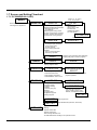
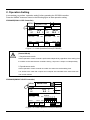
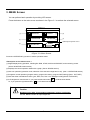
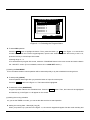
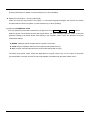
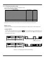
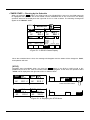
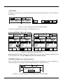
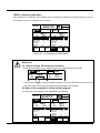
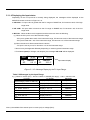
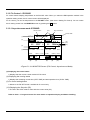
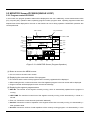
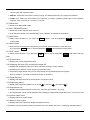
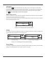
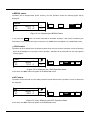
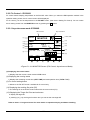
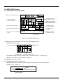
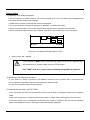
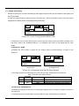
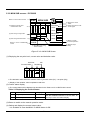
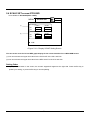
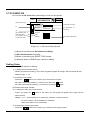
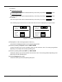
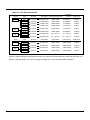
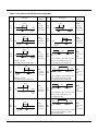
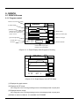
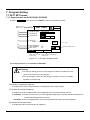
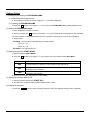
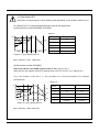
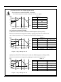
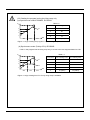
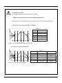
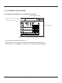
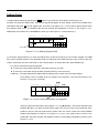
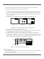
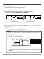
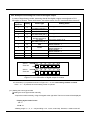
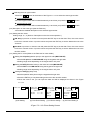
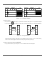
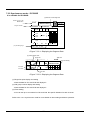
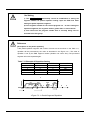
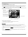
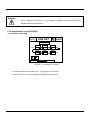
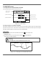
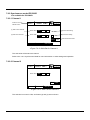
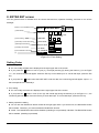
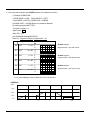
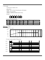
7.2 Segment Editing(SEG SET screen) When you press the EDIT button in PATT SET screen, the screen as shown in the Figure 7.2.1 will appear. You can set the program in this screen – programming each segment data (target set point, operating time, junction code, GSOAK wait and event) by the program number, and setting the total number of repetition of the current program and the number of repetition of the specific segment. 7.2.1 Asynchronous mode-IPC5000D, IPC5000S 7.2.1.1 CHANNEL 1 EXIT Button to move to PATT SET screen (1) SP 00 1 99:59 1 -100.0 ▲ SEGMENTS PID TIME -100.0 02 (17) C -100.0 01 01.23 FRI 12. 59. 50 SEG SET PROGRAM 0 SEG (2) 99:59 1 99:59 INS ▼ 3 JC GS Hr:Min EVENT SET 0 P T T P P P 0 M M M A 0 0 0 P T T P P P 0 M M M A 0 0 2 P T T P P P 0 M M M A 0 0 DEL EDIT RPT SP : -200.0 to 500.0 <Figure 7.2.1> Displaying the Segment Data (CH1) (1) Displays the number of setting programs. (2) Displays the number of total registered segments. ◈ Displaying the segment data (6)TIME (4) Target set point (3) Segment No. (5) PID Gr. PROGRAM SEG 00 0 SP C PID TIME 50.0 1 TIME unit (7) Junction code SEGMENTS 99:59 3 Hr:Min JC GS 0 EVENT SET P T T P P P 0 M M M A 0 0 (8) GSOAK number <Figure 7.2.1.1(a)> Segment Components (3) Displays the segment sequence number. ● Displays 3 segments per page. - 71 - (9) Event setting (4) Displays the target set point, and temperature and other unit of the channel that is currently being set. (5) The PID item will appear if the SEGMENT is selected for PID group type. The following section describes the case that the selected PID group is in segment. (6) Segment operation time. (7) Junction code for operation at the time of segment completion. (8) Displays the number for the GSOAK wait function. (9) The number of segment event output operation. ◈ Displaying the editing buttons ▲ ▼ INS DEL EDIT RPT (15) FIX (10) (11) (12) (13) (14) (16) <Figure 7.2.1.1(b)> Segment Editing Buttons (10) Displays the previous page. (11) Displays the next page. (12) INS: Inserts the segment. (13) DEL: Deletes the segment. (14) EDIT: Starts segment editing. (15) Button to move to the repetition setting screen. (16) Button to move to the fix control setting screen. (See the junction code) (17) Displays the SP setting range by channel. No Setting (12), (13) and (14) buttons are not allowed to use. ● You cannot use program number if it is included in the link group or the currently running program. ● You can change the value for other program number, or in the fix controller operation or STOP mode. - 72 - 7.2.1.2 CHANNEL 2 (CH2)-IPC5000D It is available for IPC5000D in case of Asynchronous mode. (2) Total number of segments Button to move to PATT SET screen (1) Current program number PROGRAM 16 SEGMENTS SEG 00 01 02 ▲ SP 01.23 FRI 12. 59. 50 SEG SET EXIT C PID TIME -100.0 -100.0 -100.0 ▼ 1 99:59 1 99:59 1 99:59 INS JC GS 4 Hr:Min EVENT SET 0 P T T P P P 0 M M M A 0 0 0 P T T P P P 0 M M M A 0 0 0 P T T P P P 0 M M M A 0 0 DEL EDIT (9) Event setting RPT SP: -200.0 to 500.0 <Figure 7.2.1.2> Displaying the Segment Data (CH2) (1) The program number display starts from 16. (9) The display of events may be different depending on the allocation of digital output. * Refer to the ‘7.2.1.1 CHANNEL 1’ section for other settings and button operation. - 73 - Setting Order (1) Start program editing by pressing the EDIT button of (12) as shown at the bottom of the Figure 7.2.1. (2) When you press the EDIT button, the numeric keypad will appear, and the setting cursor will be located at the temperature Set point (SP) of the segment #0, as shown in the Figure 7.2.1. If the current program doesn’t have any segment data at all, all initialized data will be inserted and displayed as shown in the Figure 7.2.1.3. Additionally, the number in the “SEGMENTS” section (2) in the Figure 7.2.1, will increase by 1. PROGRAM SEG 00 0 SEGMENTS SP C PID TIME 0.0 1 0:00 4 Hr:Min JC GS 0 EVENT SET P T T P P P 0 M M M A 0 0 Cursor <Figure 7.2.1.3> Setting Segment Data (3) To set the segment data or to move the setting cursor, press the arrow key on the numeric keypad or the Ent key. If the input data remains in the allowable range, the value will be accepted and the cursor moves to the next column. Otherwise, the cursor will remain in the current position. To cancel data input, press the Esc key. (3-1) Cursor movement inside the segment ▶ To move the cursor without data input, press the arrow key you want. ▶ To move the cursor after saving the data, press the ENT key or the arrow key. c ENT key : The input data will be updated and the setting cursor moves to the next input position. If the setting cursor is located at the JC position of the segment, it will move as shown in the Figure 7.2.1.4 (a), (b), (c) and (d). np PROGRAM SEG 00 0 SEGMENTS SP C PID TIME 50.0 1 0:00 4 Hr:Min JC GS 0 EVENT SET P T T P P P 0 M M M A 0 0 o <Figure 7.2.1.4 (a)> Cursor Movement in the Segment When you press the ENT button at the Figure 7.2.1.4 (a) n position , the cursor moves to the position o. When you press the ENT button again, the cursor moves to the position p. If the position to move is set with mode event or alarm event, the cursor moves to the next available position automatically as shown in the Figure 7.2.1.4 (b). If the setting cursor moves to the position p - the event set area, the separate screen for event setting will appear as shown in the Figure 7.2.1.4 (c). - 74 - p PROGRAM SEG 0 SEGMENTS SP C PID TIME 00 50.0 1 4 Hr:Min JC EVENT SET GS 0 M T T P P P 0 M M M A 0 0 0:00 o <Figure 7.2.1.4 (b)> Cursor Movement in Segment Setting PROGRAM 0 SEGMENTS SEG 00 01 02 ▲ SP 01.23 FRI 12. 59. 50 Esc ― SEG EDIT EXIT C PID TIME JC GS -100.0 TYPE 1 99:59 0 EVENT -100.0 -100.0 1 99:59 1 99:59 INS ▼ 4 Hr:Min EVENT SET 0 P T T P P P 0 M M M A 0 0 0 P T T P P P 0 M M M A 0 0 2 P T T P P P 0 M M M A 0 0 DEL EDIT 0 2 4 6 8 1 3 5 7 9 . Ent RPT SP: -200.0 to 500.0 <Figure 7.2.1.4 (c)> Event Setting Screen If all events are set as mode or alarm events, the cursor will move to the position o, when the ENT button is pressed at the position n in the Figure 7.2.1.4 (d). PROGRAM SEG 0 SEGMENTS SP C PID TIME 00 50.0 1 0:00 00 50.0 1 0:00 o 4 Hr:Min JC EVENT SET GS 0 M M M A A A 0 M M M A M M 0 M M M A A A 0 M M M A M M n <Figure 7.2.1.4 (d)> Cursor Movement in Segment Setting d Arrow key (a) Left/Right (Í,Î) key sets the input data and moves the cursor to the left/right direction. If no input data is available at the current position, the cursor moves to the next position without data setting. The cursor moves within the segment that it currently locates only. If the cursor is located at n or o as shown in Figure 7.2.1.5(b), and the Î key is pressed, the cursor moves to the position p. If the cursor is located at p, and the Í is pressed, the cursor moves to the - 75 - position n. (b) Up/Down (Ï,Ð) key sets the input data and moves the cursor as shown in the Figure 7.2.1.5 (a) and (b). If no input data is available at the current position, the cursor moves to the next position without data setting. The cursor moves from n to o. PROGRAM SEG 00 0 SEGMENTS SP C PID TIME 50.0 1 0:00 50.0 1 Hr:Min P T T P P P 0 M M M A 0 0 n 00 4 JC GS 0 0:00 o EVENT SET 0 P T T P P P 0 M M M A 0 0 <Figure 7.2.1.5 (a)> Segment Cursor Movement n p PROGRAM SEG 0 SEGMENTS SP C PID TIME 00 50.0 1 0:00 00 50.0 1 0:00 4 Hr:Min JC EVENT SET GS 0 P T T P P P 0 M M M A 0 0 0 P T T P P P 0 M M M A 0 0 o <Figure 7.2.1.5 (b)> Segment Cursor Movement ► Press the Í,Î key to complete event data input for the current DO number and move to the next DO number. (See the Figure 7.2.1.5 (c)) n EVENT SET DO 1 o EVENT SET DO 6 P T T P P P P M T P P P M M M A 0 0 DO 7 M M M A 0 0 DO12 <Figure 7.2.1.5 (c)> Segment Cursor Movement ► If the mode event or alarm event is set for the next DO number, it will be displayed as shown in the Figure 7.2.1.5 (c). (3-2) Cursor movement for event setting The separate screen appears as shown in the Figure 7.2.1.6. The cursor moves when you press the Ï,Ð or Ent key on the keypad if the event type is greater than 2. If the input data is within the setting range, the input value will be updated and the cursor moves to the next column. If the data goes off the setting range, the cursor will remain in the current position. - 76 - ► Press the Ï,Ð key to move the cursor without entering the event data to the current DO number. ► Press the ENT or Ï,Ð key to move the cursor after saving the data. ① Ent key: If the input data is within the setting range, the input value will be updated and the cursor moves to the next column. If the data goes off the setting range, the cursor will remain in the current position. ② Esc key: If you press the ESC key during data input, setting will be cancelled and the cursor will remain in the current position. ③ Ï,Ð key: Move the cursor to the previous/next position inside the event setting screen only. n EVENT TYPE 0 n 2 EVENT TYPE EVENT TYPE DESCRIPTION TIME EVENT 11 DESCRIPTION CH1 PV-ABS-LOW ON delay 0H 0M OP point 100.0 Cut back 0H 0M DIFF 10.0 Delay(s) 10 o (a) p o p (b) (c) <Figure 7.2.1.6> Cursor Movement in the Event Setting Screen ► Cursor movement in the event setting screen (Figure 7.2.1.6) The setting cursor won’t move in the Figure (a). The setting cursor in the Figure (b) and (C) moves from the position n to o, and then p when the arrow key or Ent key is pressed. ► The current DO number in the segment moves from n to o in the current segment if the Í,Î key is pressed as shown in the Figure 7.2.1.7. If the Ent key is pressed at the position n, the cursor will move to the position p, as shown in the Figure 7.2.1.7. If no registered segment is available after the current segment, one segment will be inserted and the initialized data will be displayed. PROGRAM o SEG 00 00 0 SEGMENTS SP C PID TIME 50.0 50.0 1 1 0:00 0:00 p 0 Hr:Min JC GS 0 EVENT SET P T T P P P 0 M M M A 0 0 0 P T T P P P 0 M M M A 0 0 n <Figure 7.2.1.7> Cursor Movement in the Segment (4) Setting the target Set point ● Input the target Set point by using the keypad at the right side and press the ENT or cursor movement key to set. Or, press the Esc key to cancel. ● Sets the value the range as shown at the bottom of the screen as shown in the Figure 7.2.1.1. - 77 - (5) Setting the PID group number ● Input the PID group number to apply to the current segment. ● Range: 1 ~ 8 (6) Setting the operation time ● Input the time if the RAMP unit is TIME, or the ramp rate value if the mode is SLOPE. (For more details, refer to the Installation Manual, 3.17 SYSTEM SET.) PROGRAM SEG 0 SEGMENTS SP C PID TIME 00 50.0 999:55 9 1 0 JC GS 0 0 n Hr:Min EVENT SET P T T P P P PROGRAM SEG 00 0 SEGMENTS SP C PID TIME 50.0 1 9.9 n (a) RAMP unit = TIME Hr:Min JC GS 0 P T T P P P 0 M M M A 0 0 M M M A 0 0 o 0 EVENT SET o (b) RAMP unit = SLOPE <Figure 7.2.1.8> Time Input ● When you press the Ent or left/right key at the position n in the Figure 7.2.1.8 (a) or (b), the cursor will move to the position o. ● Setting range (a) Time input (TIME) = 00:00 ~ 99:59(Hr:Min or Min:Sec) (b) Ramp ratio input (SLOPE)= 0.0 ~ 99.99(C/min or F/min or C/sec or F/sec) <Reference> 1. When time value is changed slope to time by RAMP unit, the displayed value and operating time is changed by setting range. Ex) when slope is set to 9.9, the time is 9:59 . When slope is set to 3.50, the time is 3:50 . 2. when RAMP unit=’SLOPE’, in case of below pattern, the TIME setting is as following. Ex) SP SEG.0 SEG.1 SEG.2 SEG.3 SP.2 SP.0 SP.3 SP.1 SEG No 0 1 2 3 setting Slope0 Time1 Slope2 Time3 Remark TIME Slope.0 Time 1 Slope.2 Time 3 Checking : if [SP1-SP0] = 0 Æ TIME setting as SOAK segment. If [SP2-SP1] < 0 or if [SP2-SP1] > 0 Æ SLOPE setting as tilted segment. In SOAK segment, if the target SP is changed during setup, it shows the slope value without changing. When SOAK time = 1:00, SLOPE value becomes 1.00. - 78 - (7) Entering the JC (Junction Code) ● JC=0 : Segment Movement Moves to the next segment if the current segment is completed as shown in Figure 7.2.1.9(a). Operation at the last segment will be completed and END is displayed. PV SEG.n PV SEG.n+1 SEG.n SEG.n+1 Target SP Target SP In HOLD TIME Time n TIME Time n+1 Time n (a)> JC=0 Time n+1 (b) JC=1 <Figure 7.2.1.9> Operation on Junction Code ● JC=1 : Program Holding When the current segment is completed, operation stops temporarily as shown in Fig 7.2.1.9(b) and the HOLD status is displayed as shown in the Figure 3.1.6 (b). Press the RUN button or press the DI2 (HOLD) button for 1 time to release holding, as shown in the Figure 3.1.6 (a). ● JC=2 : Switching to Fix Control When the last segment of the current program is completed, fix control will be engaged. Additionally, the SP Tracking function will be enabled when switched to FIX control.(Refer to the Installation Manual, 3.17 SYSTEM SET.) (8) Setting G.SOAK wait function ● Use this function to suspend control operation until the process value (PV) enters within the ±WAIT value of the set point (SP). (See 7.6 WAIT SET for more details.) 0 : NONE – Do not check for the G.SOAK wait. 1 : FRONT wait check–check before the current segment is started. 2 : REAR wait check –check after the target SP is reached and operation time is terminated. 3 : ALL wait check –check during the operation. (9) Setting time and PV event data ● You can set the time or PV event to the DO terminal for event output in time of program control. ● You can input up to 12 time or PV event settings for each channel. (Figure 7.2.1.10) - 79 - PROGRAM 0 SEG 00 (17) Close window SP C SEGMENTS PID TIME JC GS -100.0 TYPE 1 99:59 11 EVENT DIFF -100.0 Delay(s) 02 ▲ ▼ SP: -200.0 1 10.0 99:59 10 INS Hr:Min EVENT SET P T T P P P 0 M M M A 0 0 100.0 0 OP point 3 0 DESCRIPTION CH1 -100.0PV-ABS-LOW 1 99:59 0 01 01.23 FRI 12. 59. 50 SEG SET EXIT P T T P P P M M M A 0 0 2 P T T P P P 0 M M M A 0 0 DEL EDIT Esc ― 0 1 2 3 4 5 6 7 8 9 . Ent RPT to 500.0 <Figure 7.2.1.10> Event Data Setting No Setting ● The PV event cannot be set for the DO terminal registered in the MODE event or ALARM event or PWM for control. The following symbols will appear. A : DO terminal is used by the alarm event. M : DO terminal is used by the mode event. R : DO terminal is used for control output(Either DO1 or DO2 is displayed). ● There is an input limitation for the asynchronous mode because the certain number of DO are allocated for each channel. If the DO number to set goes off the range of the digital output channel adjustment, the PV event cannot be set. (See the Installation Manual 3.17 SYSTEM SET for more details.) ● TIME and PV events can not be set up to 511. - 80 - Ex2. Example of allocating the event to the digital output In case of Asynchrnous mode, assuming that all the digital outputs are assigned to CH1. Allocation of events: Three mode event, two alarm event, four PV event and three event off. Digital Display Event Type Setting Items Input No. PV event PV-ABS-LOW (CH 1) TIME event TIME event PV event SP-ABS-HIGH (CH 1) PV event DV-DEV-ON (CH 1) PV event MV-ABS-LOW (CH 1) 1 P 2 3 T T 4 P 5 P 6 P 7 M END 8 M DOWN 9 M RUN 10 11 12 A - Alarm event Not used Not used Event type number is 11 Event type number is 1 or 2. Event type number is 23. Event type number is 27. Event type number is 35. Mode: END MODE ASSIGN : 7 Mode: DOWN MODE ASSIGN : 8 Mode: DOWN MODE ASSIGN : 9 ALM ASSIGN : 10 DO No. 01 02 03 04 05 06 Event No. P T T P P P DO No. 07 08 09 10 11 12 Event No. M M M A 0 0 <Figure 7.2.1.11> Allocation of digital output for events ● If the button(17) is pressed as shown in Figure 2.7.1.10, the event setting window is closed. If the ← or → is pressed, the event setting screen is opened. (9-1) Setting the event type number c Setting the event type number manually ● Input the number manually, using the keypad at the right side. The kind of event will be displayed. * Display by the kind of event 1, 2 : T 11~38 : P ● Setting range: 0, 1, 2, 11 ~ 38 (excluding 3~10, 19, 20, 29 and 30). However, 0 means event off. - 81 - d Selecting the even type number ● Press the button at the bottom of the Figure 7.2.1.12 to select the event type number. In Asynchronous mode, ● The event type number will increase/decrease by 2 each time you press the / button. / button. In Synchronous mode, ● The event type number will increase/decrease by 1 each time you press the (9-2) Description on the event type (See the Table 5.4) ● Provides the detailed description on the selected type number. (9-3) Setting the time event Setting range: 0, 1, 2 (Refer to ‘Description on the time event operation’.) c ON delay: Input hour or minute to set and press the ENT key to set the data. Then, the cursor moves to minute or second column. Input the minute and press the ENT key to set the data and move to the “Cut back”. d Cut back: Input hour or minute to set and press the ENT key to set the data. Then, the cursor moves to minute or second column. Input the minute and press the ENT key to set the data and move to the next DO number. (9-4) Setting the PV event (Refer to the Table 5.6 for more details) c Setting the OP point(operation point) or the upper limit value(MAX VALUE) ● Set the OP point or the MAX VALUE using the keypad at the right side. ● Setting range varies depending on the target value or OP point d Setting the DIFF(differential value) or the lower limit value(MIN VALUE) ● Set the DIFF or the MIN VALUE using the keypad at the right side. ● Setting range varies depending on the target value or OP point e Setting the Delay(s) (delay time) ● Set the operation delay time using the keypad at the right side. ● Press the ENT key to complete setting and move to the next DO number. ● When the event is set, you can input the data and will be displayed as shown in the Figure 7.2.1.12. EVENT TYPE 0 EVENT TYPE 2 EVENT TYPE DESCRIPTION TIME EVENT (a) No Setting 11 EVENT TYPE 25 DESCRIPTION CH1 PV-ABS-LOW DESCRIPTION CH1 SP-DEV-OFF ON delay 0H 0M OP point 100.0 MAX VALUE 100.0 Cut back 0H 0M DIFF 10.0 MIN VALUE 10.0 Delay(s) 10 Delay(s) 10 (b) Time Event Setting (c) PV Event Setting 1 (d) PV Event Setting 2 <Figure 7.2.1.12> Event Setting Screen - 82 - Reference [Description on time event operation] 1. Event type = 0: Time even output will be off in the concerned segment. 2. Event type = 1: Time event output will be on in the concerned segment. 3. Event type = 2: Set time event operation. Time event operation is associated with the segment time counter. The counter of the “ON delay” time starts with the segment time counter and the events becomes “ON” when the delay time elapses. The “Cut back” time is the off time before expiry of the segment setting time. When the delay counter is held, the “ON delay” counter will stop. 3. The Figure 7.2.1.13 shows the output operation for each time event. ON DEALY Cut back ON Program Graph Process Graph n+1 SEG n SEG n-1 SEG Segment Setting Time Delayed WAIT WAIT WAIT <Figure 7.2.1.13> Description of Time Event Operation - 83 - (10) Inserting a segment ● When you press the (12) INS button in the Figure 7.2.1.2, the new segment is inserted and filled with the initialized data as shown in the Figure 7.2.1.14. The cursor will be displayed at the position of the current segment, and the number in “SEGMENTS” increases by 1. ● The Figure 7.2.1.14 (a) shows the case that one segment is registered. PROGRAM SEG 00 0 SEGMENTS SP C PID TIME 50.0 2 1:30 1 Hr:Min JC EVENT SET GS 0 M T T P P P 1 M M M A 0 0 PROGRAM SEG 0 SEGMENTS SP C PID TIME 00 0.0 01 50.0 1 2 0:00 1:30 2 Hr:Min JC GS 0 EVENT SET 0 0 0 0 0 0 0 0 0 0 0 0 0 0 M T T P P P 1 M M M A 0 0 <Figure 7.2.1.14 (a)> Inserting a Segment ● The Figure 7.2.1.14 (b) shows the case that new segment is inserted when segment number is more than 2 . PROGRAM SEG 0 SEGMENTS SP C PID TIME 00 50.0 2 1:30 01 100.0 3 2:00 2 Hr:Min JC EVENT SET GS 0 M T T P P P 1 M M M A 0 0 0 2 M T T 0 P 0 PROGRAM SEG 0 SEGMENTS SP C PID TIME 00 50.0 2 1:30 01 50.0 2 0:00 T M M A A 0 02 100.0 3 2:00 3 Hr:Min JC EVENT SET GS 0 M T T P P P 1 M M M A 0 0 0 0 0 0 0 0 0 1 0 0 0 0 0 0 0 M T T 0 P 0 2 T M M A A 0 <Figure 7.2.1.14 (b)> Inserting a Segment ● Inserted data will be displayed as followings except the event setting data. ► When the segment number is 0, all data are initialized into 0. ► When the segment number is up to 1, - TIME : The time data is initialized into 0. - Others : The data of the previous segment are inserted and displayed No Setting * If the number of registered segments are up to 800, the insertion is not operated. (11) Deleting a segment ● When you press the (13) DEL button in the Figure 7.2.1.2, the segment whether the cursor currently locates will be deleted as shown in the Figure 7.2.1.15 and the cursor will move to the next segment. If you press the DEL button on the last segment, the cursor will move to the previous segment. Regardless of the cursor position in the segment, the segment will be deleted and the number in “SEGMENTS” will decrease by 1. - 84 - PROGRAM SEG 0 SEGMENTS SP C PID TIME 00 50.0 2 1:30 01 50.0 2 1:30 02 3 2:00 3 Hr:Min JC EVENT SET GS 0 M T T P P P 0 M M M A 0 0 0 0 0 0 0 0 0 1 0 0 0 0 0 0 0 M T T 0 P 0 2 T M M A A 0 PROGRAM SEG 0 SEGMENTS SP C PID TIME 00 50.0 2 1:30 01 100.0 3 2:00 2 Hr:Min JC EVENT SET GS 0 M T T P P P 0 M M M A 0 0 0 M T T 0 P 0 2 T M M A A 0 <Figure 7.2.1.15> Deleting a Segment (12) Page movement ● If you press the Or, if you press the ▼ ▲ in the Figure 7.1.2, the screen as shown in the Figure 7.2.1.16 (a) will be displayed. in the Figure 7.1.2, the screen as shown in the Figure 7.2.1.16 (b) will be displayed. SEG SEG SEG 03 00 01 04 01 04 02 05 02 05 00 ▼ (a) Moves to the Next Page SEG ▲ 03 (b) Moves to the Previous Page <Figure 7.2.1.16> Page Movement ● When the Event is setting, if the button (17) is pressed as shown in Figure 7.2.1.10, the event setting screen is closed, and the page movement can be set by using the button(10) and (11). (13) Switch to the repetition setting screen(RPT SET) ● If you press the button (15) in the Figure 7.1.2, the 7.3 REPEAT SET screen will appear. - 85 - (14) Setting FIX control by the JC ● Valid if the junction code (JC) of the last segment is 2. If you press the button (15) in the Figure 7.1.2, the 5.5 FIX SET screen as shown in Figure 7.2.1.17 will appear. ● PV event can be setup for FIX control. EXIT CH1 01-23 TUE FIX SET 12 .59 .31 CH2 SP 100.0 C RANGE : -200.0 RAMP OFF TIMER OFF G.SOAK 0 to 500.0 ON 01 H 59 M ON 01 H 59 M 0: NONE 1: FRONT 2: REAR 3: ALL PV EVENT 1 2 3 4 5 11 27 23 35 M 6 M 7 8 9 10 11 12 M 0 0 0 A A <Figure 7.2.1.17> FIX control setting screen - 86 - 7.2.2 Synchronous mode – IPC5000D It is available for IPC5000D. (2) Number of total segments Button to move to the MENU button Program number PROGRAM 16 SEGMENTS SEG SP1 SP2 00 02 PID TIME 1 1 -100.0 -100.0 1 1 99:59 -100.0 -100.0 1 1 99:59 INS ▼ JC GS 99:59 -100.0 ▲ (17) SP setting range C F -100.0 01 01.23 FRI 12. 59. 50 SEG EDIT EXIT 4 Hr:Min EVENT SET 0 P T T P P P 0 M M M A 0 0 0 P T T P P P 0 M M M A 0 0 0 P T T P P P 0 M M M A 0 0 DEL EDIT RPT SP1: -200.0 to 500.0 SP2: -328.0 to 932.0 <Figure 7.2.2.1> Displaying the Segment Data (4) Setting target value TIME unit (5) PID Gr. PROGRAM SEG 00 For CH1 SP1 C SP2 C 0 SEGMENTS PID TIME 50.0 1 -100.0 1 For CH2 99:59 4 Hr.Min JC GS 0 EVENT SET P T T P P P 0 M M M A 0 0 (9) Event setting For CH1 For CH2 <Figure 7.2.2.2> Displaying the Segment Data (4) Target Set point display and setting ● Sets the data for CH1 and CH2 and displays it. (5) PID group number display and setting ● Sets the data for CH1 and CH2 and displays it. (9) Event setting ● You can set up to 12 numbers for CH1 and CH2. No specific limitation for each channel. Refer to the 7.2.1 Asynchronous mode for more details on other setting and button operation. - 87 - 7.3 PEPEAT set You can set whether the entire current program will be repeated or the specific program segment will be repeated for certain times (partial repetition). (Figure 7.3) Up to 999 times of entire repetition or partial repetition can be set, and up to 5 partial repetition segments can be registered. Button to move to SEG SET screen EXIT (1) Number of entire program repetition 999 ALL REPEAT PART REPEAT No. START (2) Partial repetition segment Start segment ~ End segment CH 1 Esc ― 01-23 THU 12 .59 .31 RPT SET 1 1 2 3 PROGRAM NO. SEGMENTS END COUNT 3 999 5 5 999 6 10 10 4 0 0 0 5 0 0 0 0 5 1 6 2 7 3 8 4 9 . 0 10 Current program No. Number of segment (3) Number of partial repetition . Ent <Figure 7.3> RPT SET screen Setting Order (1) Press the button to set the data. (2) The numeric keypad will appear, which enables you to input the data. (3) The default repetition count is set to 1. Each time the program or setting sector is run, it will be taken as one time repetition. If the number of segments is 10, the setting range is 0 to 9. (4) The segment range for the initial partial repetition is set to 0 ~ 0. (5) Setting range for repetition times: 1 ~ 999 (times) - 88 - No Setting 1) The START > END relationship cannot be established in setting the segment number for partial repetition setting. Input the END first when setting the partial repetition segment. 2) If the segment number for the current program is 0 ~ 9 when setting the repetition segments, the segment number greater than 10 cannot be set. 3) You cannot use the program number that is currently being used or included in the link group. Reference [Description on the partial repetition] If the partial repetition segment and number of times are set as shown in the Table 7.11, repetition will be processed by the order as described in the Figure 7.3.1. The order of repetition is set by the END segment number (Smaller one comes first.) The processed segment will not be repeated again. Table 7.11 Example of Repetition Setting No. 1 2 3 4 5 START 0 2 5 6 0 END 3 4 5 7 7 COUNT 50 100 300 999 3 3 50 0 N-1 1 300 100 2 3 4 5 999 6 7 8 N <Figure 7.3.1> Partial Segment Repetition - 89 - 9 7.4 Program Name set(PGM NAME screen) You can assign up to 32 unique names for the programs. Assign the different name for each program for easy identification. EXIT PGM NAME TTEST - 0 No PROGRAM NAME (1) Program name (2) List of program name 01-23 THU 12 .59 .31 Esc ― 0 1 2 3 4 5 6 7 8 9 Ins . TEST - 0 TEST - 1 2 TEST - 2 3 TEST - 3 4 TEST - 4 5 TEST - 5 6 TEST - 6 7 TEST - 7 8 TEST - 8 9 TEST - 9 10 TEST - 10 0 1 Del Ent PAGE SET EDIT KEYS (6) (5) (4) (3) <Figure 7.4> Assigning the Program Name (1) Displays the name of the program. (2) Displays the list of program name and number. (3) ‘KEYS’ : Switches the keypad input mode – number, English character and special character, as follows. Esc ― 0 1 2 3 4 5 6 7 8 9 Ins . Del Ent KEYS Esc ― A B C D E F G H I J Ins . KEYS Del Ent Esc ― K L M N O P Q R S T Ins . Del Ent KEYS <Figure 7.4.1> Keypad Switching - 90 - KEYS Esc ― U V W X Y Z # ( % ) Ins . Del Ent Setting Order 1. Move the cursor to the number of the program to edit using the ▲ and ▼ button. Then, the selected program number and name will be displayed at the position (1) as shown in the Figure 7.4 . 2. Press the ‘EDIT’ button. Then, the numeric keypad and ‘KEYS’ button will appear at the right side. 3. Input 12 characters by combining numbers, English character and special characters. Then, press the Ent key to update the input name, and it will be displayed at the right side of the concerned program number (2) as shown in the Figure 7.4. Reference * The setting and editing are processed as follow, - Setting : The characters show by setting numbers, English and special characters on keypad. - Editing : The cursor is moved to a certain position, and setting a character, it is changed to new one. - Insert : If the ‘Ins’ key is pressed, the blank is inserted on the current cursor. - Delete : If the ‘Del’ key is pressed, the character on the cursor is deleted and the next character is come to the current cursor. * move the cursor during editing - → (RIGHT) : move to the right side by 1 column. - ← (LEFT) : move to the left side by 1 column. 4. Press the ‘SET’ button after setting. Then, the “PATT SET” screen will appear. The program name and number that are different from the previous one will be displayed (1) and (2) as shown in the Figure 7.1.1. If you press the EXIT button, the “PATT SET” screen will appear but the screen will not be changed item (1) and (2) as shown in the Figure 7.1.1. No Setting If the current program number is running, the current program name is not changed. - 91 - 7.5. LINK SET Screen 7.5.1 Asynchronous mode-IPC5000D, IPC5000S Register the link group if you want to group several programs sequentially. You can register up to 6 programs in a link, and set 10 links at maximum. As described in the Figure 7.5.1, the program will be executed by the order of start PROG10 Æ PROG 5 Æ PROG 4 Æ PROG 12 Æ PROG 5 Æ PROG 1 end. If a program doesn’t contain the data while running, the next program will be started. To run the link, select the RUN OBJECT to LINK in the 3. OPERATION screen. ___ Button to move to the menu screen MENU (1) Display Link number (2) Button to input the program number to set LINK No. 0 PROG PROG PROG 10 5 4 PROG PROG PROG 12 5 START (3) Program number 01-23 THU LINK SET (4) Button to delete the current program number and followings END 1 Del registered prog (5) Link number selection PATT SET LINK SET Esc ― 0 1 2 3 4 5 6 7 8 9 . Ent CH1 CH2 (6) Channel selection WAIT SET <Figure 7.5.1> LINK SET Screen (4) Button to delete the registered program ● Press the button (2) in the Figure 7.5.1 to display the button in the screen. (6) Channel selection : It is available for IPC5000D. Setting Order 1. When you press the program number button (2) while the link number is “0”, the keypad will appear at the right side. Input the program number. Press the ENT key to set, or the ESC key to cancel. 2. Program numbering starts sequentially from the starting point. The program number cannot be entered in the middle. 3. To set other link number, press the (5) ▲, ▼ button to change the link number. Then, start from step 1 again. 4. Press the (4) DEL registered patt button to delete the registered program number. Then, the program number after the selected number will be removed. - 92 - Warning If (4) is deleted in the Figure 7.5.1, all programs registered current and next will be deleted and displayed as (blank). 7.5.2 Synchronous mode-IPC5000D It is available for IPC5000D 01-23 THU LINK SET MENU LINK No. 12. 59. 31 0 PROG PROG PROG 10 5 4 PROG PROG PROG 12 5 1 START PATT SET LINK SET END WAIT SET <Figure 7.5.2> LINK SET Screen No channel selection is available and 0 ~ 9 link group can be entered. * Refer to the 7.5.1 Asynchronous Mode to set the program number. - 93 - 7.6. WAIT SET screen 7.6.1 Asynchronous mode-IPC5000D, IPC5000S You can use this screen to set the GSOAK wait function. Button to move to MENU screen (1) WAIT value OFF/ON 01.23 THU 12. 59. 31 WAIT SET EXIT WAIT Value OFF ON (2) Wait value setting C 9.9 Range : 0.0 to 9.9 (3) WAIT time OFF/ON WAIT TIME (4) Wait time setting OFF 59 S 99 M ON Channel selection button CH1 CH2 PATT SET LINK SET WAIT SET <Figure 7.6.1> WAIT Setting For channel selection, it is available for IPC5000D Wait setting is designed to wait until the Process value (PV) comes within the ±WAIT scope of the target Set point (SP) after running FIX control, or wait until the Process value (PV) comes within the ±WAIT scope of the Set point (SP) after running the program, so that the control can be managed stably. Setting Order 1. Set the WAIT value ON to check the GSOAK wait. Press the , set the proper value. ● Range: 0.0 ~ 9.9 2. Set the WAIT time ON to check within the time. Press the , set the proper time. ● Range: Max. 99H 59M or 99M 59S Warning If the WAIT Value is OFF, the GSOAK wait does NOT check. FRONT WAIT Start ALL WAIT REAR WAIT SEG 0 SEG 1 CH1 SEG 2 SEG 3 <Figure 7.6.1.1> Description on the GSOAK Wait Function - 94 - Reference [Description on the GSOAK (Guaranteed SOAK) function] You can set the GSOAK mode using the following three methods. If the PV doesn’t enter into the wait zone, the operation state will be “WAIT”. Wait zone = SP ± wait value (1) Front wait check If the Wait value is set ON, check will be started before the current segment and operation will be pending within the wait time setting. The time event does not work. Example 1) If the PV enters within the wait zone of the target set point before the wait time elapses, waiting of the operation status will be released and the current segment will be executed. (Figure 7.6.1.2) SEG.n-1 Target SP SEG.n wait zone SP PV Delay in wait time Event Wait time <Figure 7.6.1.2> Front Wait Operation (1) Example 2) If the PV does not enter within the wait zone of the target set point and the wait time elapses, waiting of the operation status will be released and the current segment will be executed. (Figure 7.6.1.3) SEG.n-1 Target SP SEG.n wait zone SP PV Delay in wait time Event Wait time <Figure 7.6.1.3> Front Wait Operation (2) - 95 - (2) Rear wait check If the Wait value is set ON, check will be started before completing the current segment and current operation will be pending within the wait time. The time event output will be maintained. Example 1) If the PV enters within the wait zone of the target Set point before the wait time elapses, waiting of the operation status will be released, and the current segment will be completed, and the next segment will be processed. (Figure 7.6.1.4) Target SP SEG.n SEG.n+1 wait zone SP PV Delay in wait time Event Event Wait time <Figure 7.6.1.4> Rear Wait Operation (1) Example 2) If the PV does not enter within the wait zone of the target Set point and the wait time elapses, waiting of the operation status will be released and the current segment will be completed, and the next segment will be processed. (Figure 7.6.1.5) Target SP SEG.n SEG.n+1 wait zone SP PV Delay in wait time Event Event Wait time <Figure 7.6.1.5> Rear Wait Operation (2) - 96 - (3) All (Entire) wait check If the Wait value is set ON, check will be started while running the current segment and current operation will be pending within the wait time. At this time, the remained segment time will not be decreased and the time event output will be maintained. Example) If the PV does not enter within the wait zone of the current target Set point, processing of the current segment will be suspended. (Figure 7.6.1.6) If the wait time elapses or the PV enters in the wait zone of the target Set point, waiting of the operation status will be released and the following control operation will continue. And, check again if PV enters in the wait zone, if not, the operation repeats the above procedure. Target set point (SP) wait zone SP PV Wait time <Figure 7.6.1.6> All Wait Operation - 97 - 7.6.2 Synchronous mode-IPC5000D It is available for IPC5000D. 7.6.2.1 Channel 1 Button to move to MENU screen EXIT 01.23 THU 12. 59. 31 WAIT SET (1) WAIT value OFF/ON WAIT Value (3) WAIT time OFF/ON WAIT TIME OFF ON 9.9 (2) Wait value setting C Range : 0.0 to 9.9 OFF 99 M ON 59 S CH1 CH2 PATT SET LINK SET (4) Wait time setting Channel selection button WAIT SET <Figure 7.6.2> Wait Set for Channel 1 The wait value will be set each channel. Refer to the 7.6.1 Asynchronous Mode for more information on other settings and operation. 7.6.2.2 Channel 2 EXIT 01.23 THU 12. 59. 31 WAIT SET WAIT Value OFF ON 9.9 C Range : 0.0 to 9.9 CH1 CH2 PATT SET LINK SET WAIT SET <Figure 7.6.3> WAIT set for channel 2 The wait time is not set in CH2, and button (3) and (4) are not shown. - 98 - 8. EXTRA SET screen You can general items of IPC5000 such as current date and time, operation handling, and time to turn off the backlight. Button to move to MENU screen MENU (1) Date setting EXTRA SET DATE SET 01.23 THU 12. 59. 31 2004 Y 01 M 23 D 4 W 0:SUN 1:MON 2:TUE 3:WED 4:THU 5:FRI 6:SAT (2) Time setting TIME SET 12 H 59 M 30 S (3) Run/Stop Lock/Unlock button RUN LOCK UNLOCK (4) Backlight time setting BACK LIGHT (5) Display SP OFF/ON SP DISP (6) SP CHANGE Lock/Unlock SP CHANGE 10 LOCK M OFF ON UNLOCK LOCK EXT SET (7) <Figure 8.1> Extra Setting Setting Order 1. Date setting ▶ You can modify the date that is displayed at the right upper side of the screen. ▶ If you press the button in front of year (Y), month (M) and day (D) among the buttons (1) in the Figure 7.1.1, the number keypad will appear. Press the Ent key to save data input. To cancel data input, press the Esc key. ▶ If you press the button below the DATE SET to set the date, the number keypad will appear. Input 0 ~ 6 that corresponds to the weekdays. 2. Time setting ▶ You can modify the time that is displayed at the right upper side of the screen. ▶ If you press the button in front of hour (H) and minute (M) among the buttons (2) in the Figure 7.1.1, the number keypad will appear. Press the Ent key to save data input. To cancel data input, press the Esc key. 3. Setting operation handling ▶ You can lock the RUN/STOP button located at the right upper side. If you set the lock, the RUN/STOP button will be hidden. Therefore, you cannot handle the RUN/STOP function. ▶ LOCK : The RUN/STOP button will be disabled. (Handling is not permitted), UNLOCK: The RUN/STOP button will be enabled. (Handling is permitted) - 99 - MENU MONITOR RUN CH1 PV -52.7 SP 5.0 01-23 TUE 12 .59 .31 STOP CH2 PV -85.7 C SP 32.0 DEMO PRG-0 0 SEG No 0 LEFT TIME 02H 59 M Part RPT 1 ALL RPT 1 LINK No 0 TOTAL 0000 H 01 M F DEMO PRG-16 16 SEG No 0 LEFT TIME 02H 00 M 00 H Part RPT 1 ALL RPT 1 LINK No 0 TOTAL 0000 H 00 M RUN LOCK=UNLOCK appeared. SUB RUN LOCK=LOCK disappeared <Figure 8.2> MONITOR screen (RUN LOCK=LOCK) 4. Setting the backlight time ▶ You can set the time to turn off the backlight time by pressing the button (4) in the Figure 7.1. Set to “0” to leave the backlight in the ON state. You cannot set the minimum 1 minute. Input the value bigger than at least 2 minutes. e.g.,) The value in the section (4) of the Figure 8.1 means that the backlight will be off after 10 minutes. 5. Setting display SP option ▶ You can choose the display of SP value either fixed value or working value. OFF : Display the working SP. ON : Display the Target SP only. 6. Setting SP CHANGE option ▶You can choose Target SP change during progressing SOAK segment of Program. UNLOCK : Target SP can be changed. LOCK : Target SP can not be changed. 7. Confirm the all setting and redisplay - 100 - Appendix I: Operation Example 1. Program Control 1-1. Running the program without the repetition function (1) Setting OPERATION - OPER MODE = PGM, RUN OBJECT = PATT - RUN MODE = QUICK, POWER FAIL = BREAK (2) RAMP UNIT = TIME(refer to Installation Manual) (3) setting program(PATT SET) - Program number = 0 -Start mode: TIME (4) PROGRAM setting(SEG EDIT) Table A-1. Segment Setting (Program NO. = 0) SEG SP TIME JC EVENT SET GS 00 01 02 03 04 05 25.0 25.0 50.0 50.0 10.0 10.0 00 : 15 0 . 0 01 : 00 0 . 0 0 0 T1 0 P1 M M M 0 0 0 0 0 0 T2 0 P1 M M M 0 0 0 0 00 : 15 0 ..0 T1 0 01 : 00 T1 0 T3 P3 P2 M 00 : 15 0 .0 0 .0 01 : 00 0 . 0 0 P3 P2 M M M 0 M M 0 0 0 0 0 0 0 0 0 T1 0 P1 M M M 0 0 0 T2 T4 0 0 P1 M M M 0 0 0 0 0 * For T1~ T3, these are displayed the character ‘T’. Table A-2. TIME EVENT setup EVENT No. 0 No TYPE T1 1 T2 2 T3 2 T4 2 Event OFF ON-delay 00H 15M 00H 20M 00H 30M Cut back 00H 00M 00H 20M 00H 00M - 101 - Remark For T1 to T3, ‘T’ will be displayed in setup screen. For channel setting of events, it is available for IPC5000D and NOT for IPC5000S. Table A-3. PV EVENT setup No TYPE Assign P1 11 CH1 P2 13 CH1 No TYPE Assign P3 23 CH1 Description PV-ABS-LOW PV-ABS-HIGH Description SP-DEV-OFF OP point 30.0 40.0 MAX value 55.0 DIFF 2.0 2.0 MIN value 30.0 Delay(s) 10 0 Delay(s) 0 Table A-4. MODE EVENT setup For setup of data, refer to the Installation Manual ‘3.11 MODE EVENT set. No 41 42 43 MODE RUN UP DOWN Assign CH1 CH1 CH1 Mode Assign DO6 DO 7 DO 8 * ASSIGN : It is channel to be assigned for event output. Table A-5. ALARM EVENT setup For setup of data, refer to the Installation Manual ‘3.12 ALARM event set. Alarm No TYPE Assign Description MAX Value MIN Value Assign 24.0 0.0 61 DO 9 DV-DEV-ON 33 CH1 49.0 25.0 62 DO 10 DV-DEV-ON 33 CH1 80.0 50.0 63 DO 11 DV-DEV-ON 33 CH1 - 102 - Delay(s) 2 2 2 - Press the RUN button in the MONITOR screen to start PROGRAM control. c Progress of PROGRAM(check in the GRAPH screen.) PV = 50.0 C 100ºC 75ºC 50ºC 25ºC 0ºC 0 SEG 0 1 SEG 1 2 SEG 2 dTIME EVENT operation(Timing Chart) DO 1 DO 2 DO 3 ePV EVENT operation DO 4 DO 5 fMODE EVENT operation DO 6 DO 7 DO 8 gALARM EVENT operation DO 9 DO 10 DO 11 - 103 - SEG 3 3 SEG 4 4H SEG 5 1-2. Running the program having the repetition function Set the program number “0” (Table A-1) for the CH1. No GSOAK setting is assumed. Input the values shown in the Table A-6. <Table A-6> Setting Repetition(REPEAT set screen) ALL REPEAT 2 PART REPEAT No 1 START 0 END 3 COUNT 3 - Press the RUN button in the MONITOR screen to start PROGRAM control. c Programming (Check in the graph screen.) Current PV = 50.0 C 100ºC 75ºC 50ºC 25ºC 0ºC 0 4 8 - Refer to Table A-2, A-3, A-4 and A-5 for event setting. - 104 - 12 16 18 1-3. Running the program with SLOPE(without the repetition function) (1) Setting OPERATION - OPER MODE = PGM, RUN OBJECT = PATT - RUN MODE = QUICK, POWER FAIL = BREAK (2) RAMP UNIT = SLOPE(Refer to Insatllation Manual) (3) setting program(PATT SET) - Program number = 0 -Start mode: SSP -Start SP1 = 0.0 (4) PROGRAM setting(SEG EDIT) Table A-7. Segment Setting (Program NO. = 0) SEG SP TIME JC EVENT SET GS 00 25.0 01 25.0 02 50.0 03 50.0 04 10.0 05 10.0 0 0 . 50 0 . 0 M M 0 0 01 : 00 0 . 0 1 . 00 T1 0 0 0 0 0 Segment time = (25-0)/0.5=0:50 0 0 P3 P2 M M M 0 0 .0 0 SLOPE segment 0 T2 0 P1 M M M 0 0 . 50 0 ..0 01 : 00 0 T1 0 P1 M 0 0 0 SLOPE segment Segment time = (50-25)/0.5=0:50 T1 0 T3 P3 P2 M M M 0 0 .0 0 01 : 00 0 . 0 0 0 0 0 T1 0 P1 M M M 0 0 0 T2 T4 0 0 P1 M M M 0 0 0 0 SLOPE segment Segment time = (50-10)/1.0=0:40 0 * For T1~ T3, these are displayed the character ‘T’. ** For event settings, refer to Table A-2, A-3, A-4 and A-5. <GRAPH> 100ºC 75ºC 50ºC 25ºC 0ºC 0 1 2 3 - 105 - 4 5H 2. Fix Control - Control mode = ASYNC, CH1 - SP = 60.0 C - RAMP = ON,1.0 C/min (Processing time: 60 minutes) - TIMER = ON, 01H 30M - GSOAK = NONE (No GSOAK wait function) - EVENT 01 02 03 04 05 06 11 13 0 21 0 M Check the PV event set point No 11 13 21 Mode CH1 CH1 CH1 Type PV PV SP Range ABS ABS ABS Level LOW HIGH HIGH OP-point 30.0 40.0 30.0 DIFF 2.0 2.0 5.0 Delay(s) 10 0 0 Mode event = RUN Progress PV = 25.0ºC 100ºC 75ºC 50ºC 25ºC 0ºC 0 1 2 PV event output operation (Timing chart) DO 1 DO 2 DO 3 DO 4 DO 5 DO 6 - 106 - 3 4H HONEYWELL ASIA PACIFIC AFFILIATES Australia Honeywell Limited 5 Thomas Holt Drive North Ryde NSW 2113 Phone: (61) 2-9370-4500 Fax: (61) 2-9370-4525 Toll Free: 1300-36-39-36 Toll Free Fax: 1300-36-04-70 e-mail: [email protected] Web: www.honeywell.com.au China – PRC – Beijing Honeywell China Inc. 15F Han Wei Plaza, East Tower No.7 Guang Hua Road Choyang District Beijing 100020, P.R.C. Phone: (86) 10 6561-0208 Ext. 205 Fax: (86) 10 6561 0618 e-mail: [email protected] China – PRC – Shanghai Honeywell (Tianjin) Ltd. 23F Tower B City Center, 100 Zun Yi Road, Shanghai 200051, P.R.C. Phone: (86) 21 6237-0237 Ext. 305 Fax: (86) 21 6236 1237 e-mail: [email protected] China – Hong Kong S.A.R Honeywell Ltd. 25F Honeywell Tower Olympia Plaza 255 King’s Road North Point, HongKong Phone: (852) 2331-9133 Fax: (852) 2331-9998 e-mail: [email protected] China – PRC – Shenzhen Honeywell China Inc. Units 04-07, 32F Shenzhen Kerry Center Renminnan Road, Luo Hu District Shenzhen 518001, P.R.C. Phone: (86) 755-518-1226 Fax: (86) 755-518-1221 e-mail: [email protected] Indonesia Honeywell Indonesiath Pte Ltd. Wisma Budi, #405 4 Floor H.R. Rasuna Said Kav C-6 Jakarta 12940, Indonesia Phone: (6221) 521-3330 Fax: (6221) 521-3735 Industrial Measurement & Control Honeywell Pte LTD Honeywell Building 17 Changi Business Park Cetral 1 Singapore http://www.honeywell.com e-mail: [email protected] India TATA Honeywell Ltd. 55A 8&9 Hadapsar Industrial Estate Pune 411013, India Phone: (91) 20 6875-532 Fax: (91) 20 6875-535 e-mail: [email protected] Japan Honeywell Inc. Sensing&Control TF B/D 14-6 Shibaura 1-Chome Minato Ku Tokyo 105-0023 Japan Phone: (81) 3 5440-1425 Fax: (81) 3 5440-1368 e-mail: [email protected] South Korea Honeywell Korea Co. Ltd. 18F KukJe Center B/D 191 HanGangRo-2Ga YongSan-Gu, Seoul, 140-702, Korea Phone: (82) 2 799-6176 Fax: (82) 2 792-9013 e-mail: [email protected] Web: www.honeywell.co.kr Malysia Honeywell Engineering Sdn Bhd 2F Wisma CSA No.4 Jalan Bersatu 13/4 46200 Petaling Jaya Selangor Darul Ehsan Phone: (603) 7950 4759 Fax: (603) 7958 8922 e-mail: [email protected] New Zealand Honeywell Limited 264 Mt. Eden Road Mt. Eden Auckland New Zealand Phone: (64) 9 623-5050 Fax: (64) 9 623-5060 Toll Free: 0800 202-088 e-mail: [email protected]. au Philippines Honeywell Systems (Philippines) Inc. E-1507A, 15F Tektite Tower 1 Exchange Road, Ortigas Center Pasig City 1605, Philippines Phone: (63) 2 636 1649 Fax: (63) 2 636 1650 e-mail: [email protected] Sensing&Control Asia Pacific Headquarters Honeywell Building 17 Changi Business Park, Central 1 Singapore 486073 Phone: (65) 355-2828 Fax: (65) 445-3033 Web: www.honeywell.com/sensing e-mail: [email protected] Singapore Honeywell South East Asia Honeywell Private Limited Honeywell B/D 17 Changi Business Park, Central 1 Singapore 486073 Phone: (65) 355-2828 Fax: (65) 445-3033 Web: www.honeywell.com/sensing e-mail: [email protected] Thailand Honeywell Systems (Thailand) Ltd. 252/121 25F Muang Thai-Phatra Office Tower II Ratchadapis Road, Huay Khwang Bangkok 10320, Thailand Phone: (662) 693-3099 Fax: (662) 693-3085 e-mail: [email protected] Taiwan R.O.C. Honeywell Taiwan Ltd. 10F Honeywell B/D 168-1 Lien Chen Road, Chung Ho City Taipei Hsien, Taiwan R.O.C. Phone: (886) 2 2245-1000 Fax: (886) 2 2245-3242 e-mail: [email protected] For Countries (SEAsia) Listed below, See Honeywell SEAsia Regional Office Bangladesh Cambodia Guam Laos Myanmar Nepal Pakistan Sri Lanka Vietnam East Timor