1
Excel 50
CONTROLLER
USER GUIDE
Copyright © 2002 Honeywell Inc. • All Rights Reserved
EN2B-0137GE51 R0902
74-3030-3
EXCEL 50 USER GUIDE
Trademark Information
EN2B-0137GE51 R0902
Echelon, LON, LONMARK, LONW ORKS, LonBuilder, NodeBuilder, LonManager,
LonTalk, LonUsers, LonPoint, Neuron, 3120, 3150, the Echelon logo, the LONMARK
logo, and the LonUsers logo are trademarks of Echelon Corporation registered in
the United States and other countries. LonLink, LonResponse, LonSupport, and
LonMaker are trademarks of Echelon Corporation.
2
EXCEL 50 USER GUIDE
CONTENTS
Revision overview ........................................................................................................................................................................ 5
About This User Guide ................................................................................................................................................................. 5
Operator's terminal....................................................................................................................................................................... 7
Password Procedure .................................................................................................................................................................... 9
Modifying a Password ............................................................................................. 10
Plant Key...................................................................................................................................................................................... 11
TODAY Function ..................................................................................................... 12
Time Program Key ...................................................................................................................................................................... 15
System Time ........................................................................................................... 16
Setting Date and Time........................................................................................ 16
Daylight Saving................................................................................................... 17
Daily Program ......................................................................................................... 18
Modifying a Daily Time Program ........................................................................ 19
Creating a New Daily Time Program .................................................................. 20
Deleting a Daily Time Program........................................................................... 21
Copying a Daily Time Program........................................................................... 21
Weekly Program ..................................................................................................... 21
Annual Program ...................................................................................................... 22
Data Points / Parameters Key.................................................................................................................................................... 25
Data Points ............................................................................................................. 28
Data Points Sequence........................................................................................ 29
Hours Run .......................................................................................................... 32
Manual Operation ............................................................................................... 33
Parameters ............................................................................................................. 34
Points in Trend ................................................................................................... 36
Parameter List .................................................................................................... 36
System Information ............................................................................................ 37
Hardware Interface Configuration....................................................................... 39
DDC Program Cycle Times ................................................................................ 42
Buswide Access ................................................................................................. 43
Trend Buffer........................................................................................................ 44
Flash EPROM..................................................................................................... 44
Alarms Key .................................................................................................................................................................................. 46
Start-up sequence ...................................................................................................................................................................... 49
Controller Setup ...................................................................................................... 51
Select Application ................................................................................................... 54
Request Download.................................................................................................. 55
Data Point Wiring Check......................................................................................... 56
Adjustable Remote Trend Buffer (V2.03.x) ............................................................. 57
Operator Access Levels ............................................................................................................................................................. 59
Time Program Description......................................................................................................................................................... 59
Data Points / Parameters Description....................................................................................................................................... 61
Data Point Attributes ............................................................................................... 62
Operating Mode.................................................................................................. 63
Hours Run .......................................................................................................... 63
Technical Address.............................................................................................. 64
User Address...................................................................................................... 64
Suppress Alarm .................................................................................................. 64
Alarm Description....................................................................................................................................................................... 64
3
EN2B-0137GE51 R0902
EXCEL 50 USER GUIDE
EN2B-0137GE51 R0902
4
EXCEL 50 USER GUIDE
REVISION OVERVIEW
The following pages have been changed from the previous issue of this document:
page
8
change
The meaning of the string "***" has been explained.
The consequences of setting the bus ID to a non-zero value
have been explained.
Additional information on the bus ID has been added.
A screen which will appear if the Excel 50 controller is
connected to a C-bus has been explained and the necessity
of appending bus numbers to the user addresses when
multiple Excel 50 controllers with the same application
program are attached to the C-bus described.
The necessity of appending the controller number and the
controller name when multiple Excel 50 controllers having the
same configurable application program are attached to the Cbus is described.
39
52
54
64
ABOUT THIS USER GUIDE
This Excel 50 controller can be used in two different ways:
1.
The Excel 50 controller can be used with embedded applications. Preconfigured applications stored in memory in the application module are selected by
entering a specific code via its MMI or an external interface.
2.
The Excel 50 controller can also be used with standard or custom applications
created with the CARE software package and downloaded into the controller.
Custom applications may have different screens and sequences than are
shown in this document. The screens show here must be considered only as
examples.
Differences between these two uses of the Excel 50 are noted where appropriate.
NOTE: The format of the date is determined by the Engineering Units:
— US - mm/dd/yyyy
— Europe - dd.mm.yyyy
The start-up sequence is an exception to this: The date in the start-up
sequence must always be entered in the European format as shown
above.
5
EN2B-0137GE51 R0902
EXCEL 50 USER GUIDE
EN2B-0137GE51 R0902
6
EXCEL 50 USER GUIDE
0000040c
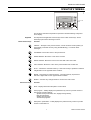
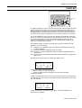
OPERATOR'S TERMINAL
LCD DISPLAY
FAST ACCESS
KEYS
C
BASIC FUNCTION KEYS
The Excel 50 controller incorporates an operator's terminal featuring a keyboard
and a display.
Keyboard
Basic function keys
The keyboard has eight basic function keys and four fast-access keys. These
twelve keys perform the following functions:
Function
CANCEL – Escapes to the previous screen, cancels incorrect entries (unless you
have already confirmed the entry using the ENTER key), or confirms alarm
messages.
UP ARROW– Moves the cursor to the previous line.
DOWN ARROW– Moves the cursor to the next line.
RIGHT ARROW– Moves the cursor to the next field of the current line.
LEFT ARROW– Moves the cursor to the previous field of the current line.
PLUS – Increases a numerical value by 1 each time the key is pressed or switches
a digital status to the opposite status condition.
MINUS – Decreases a numerical value by 1 each time the key is pressed or
switches a digital status to the opposite status condition.
ENTER – Confirms any changes made or moves to the next screen.
Fast-access keys
Function
Plant – Displays data about the plant's current status.
Time program – Initially displays the password entry screen to provide access to
change time program settings:
System clock (current date, time, daylight savings dates),
Daily time programs,
Weekly time programs,
Annual time programs.
Data points / parameters – Initially displays the password entry screen to provide
access to information on:
7
EN2B-0137GE51 R0902
OPERATOR’S TERMINAL
EXCEL 50 USER GUIDE
Physical, remote and pseudo user addresses, parameters, system data, DDC
program cycle time, buswide access and Flash EPROM.
Alarms – Displays alarm information on:
Alarm history, points currently in an alarm condition, critical and non-critical
alarms.
RESET
A RESET can be achieved by pressing the following keys simultaneously:
IMPORTANT
After performing a RESET all data in the RAM and the configuration codes
are lost.
+
DOWN ARROW and MINUS: Reboots the controller and starts the start-up
sequence.
A RESET can also be achieved by pressing the hardware RESET button at the rear
of the controller housing under Terminal Block B.
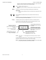
Display
The display shows four lines of alphanumeric text with 16 characters per line.
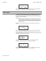
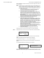
A typical screen contains fields, either a cursor or a blinking character, 'up' and
'down' arrows, and may look like the following example:
Field name. In this User
Guide, it is shown in a
different font and within arrow
brackets.
Cursor. Can be moved with
the arrow keys.
<field name> >NEW
>06:00 AH1_occ ↑
>06:00 AH1_tsp 1
>06:00 AH1_tsp ↓
Arrows indicate a list which can
be scrolled with the up and down
arrow keys.
Specifies the number of pages
the list will be scrolled when the
right or left arrow key is pressed.
Number can be changed with '+'
and '–' keys.
Selected character blinking in display.
In this User Guide, it is shown
underscored. Its value can be
changed with the '+' and '–' keys.
Places where the cursor can
be moved to. Gray arrows not
visible on real display.
NOTE: If the string "*****" should appear, this means that currently no value is
available.
The field name is sometimes shown in this User Guide to make a screen easier to
understand. Field names are not visible on the Excel 50 display.
NOTE: The screens shown in this User Guide are examples and may differ slightly
from the screens visible on your Excel 50 controller.
EN2B-0137GE51 R0902
8
EXCEL 50 USER GUIDE
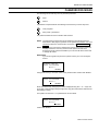
PASSWORD PROCEDURE
The following fast-access keys are not password-protected:
Plant
Alarms
A password is required before the following fast-access keys can be fully used:
Time programs
Data points / parameters
The password allows access to sensitive data screens.
NOTE: The password procedure will not be repeated in the following sections.
Refer back to this page for guidance on the password procedure. For more
information about the access levels, see section "Operator Access Levels".
NOTE: If no password or the level-2 password is entered, only those screens are
displayed which the user may access at that operator access level.
Entering the level-3 password enables you to access all data screens and
to change all values.
IMPORTANT
If you have forgotten the password, please contact your local Honeywell
branch.
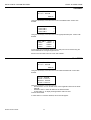
Please Enter
Your Password
>****
>NEXT
Using the arrow keys, move the cursor to the password field. Confirm with ENTER.
Please Enter
Your Password
>3***
>NEXT
Enter the password by changing the number displayed using the '+' or '–' keys and
by moving to the next digit using the right arrow key (the underscored character will
be blinking in reality).
For operator access level 1, no password has to be entered.
Please Enter
Your Password
>***5
>NEXT
Confirm with ENTER.
9
EN2B-0137GE51 R0902
PASSWORD PROCEDURE
EXCEL 50 USER GUIDE
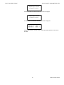
Please Enter
Your Password
>****
>NEXT
Using the arrow keys, move the cursor to 'NEXT'. Confirm with ENTER to proceed
to the next screen.
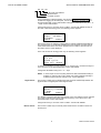
Modifying a Password
If the level-3 password has been entered, the level-2 and level-3 passwords can be
changed:
Please Enter
Your Password
>****
>CHANGE
>NEXT
Using the arrow keys, move the cursor to the 'CHANGE' field. Confirm with ENTER.
The following screen appears.
Change Password
Level 2:>2222
Level 3:>3333
>BACK
Using the arrow keys, move the cursor to the password to be changed. Confirm with
ENTER.
Change the password using the '+' or '–' keys and by moving to the next digit using
the right arrow key. Confirm with ENTER.
Change Password
Level 2:>1775
Level 3:>3333
>NEXT
After you have finished changing the passwords, use the arrow keys to move the
cursor to 'BACK'. The previous screen will be displayed.
NOTE: The default level-2 password is '2222'.
The default level-3 password is '3333'.
EN2B-0137GE51 R0902
10
EXCEL 50 USER GUIDE
0000040c
PLANT KEY
LCD DISPLAY
FAST ACCESS
KEYS
C
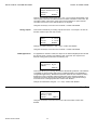
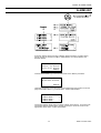
BASIC FUNCTION KEYS
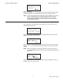
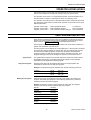
The 'Plant' procedure is used to choose the time program where changes should be
made to in the 'Time program' procedure and to make temporary changes to the
daily time program. The first screen of the 'Plant' procedure is the start screen. It is
the default screen and is always visible when no other screen has been selected.
This start screen will also be displayed if no key has been pressed for a long time.
The screen displays the name of the first time program, the application status, the
current day, the date, and the time. The next switching time of the first user address
of the time program with its current value/status is displayed below. Each time
program can be assigned to more than one user address. Each application can
have up to 20 different time programs.
The application status is shown in the upper right corner of the display and will
appear as one of the following:
Init
Initializing—The application tasks are started, and data points and memory
are being initialized.
Run Running—All relevant application tasks are running.
Shut Shutdown—All relevant application tasks are halted. The application stops
step by step.
Stop Stopped—Some or all relevant application tasks are stopped. The application
does not run.
Press the 'Plant' fast-access key to display the default screen.
<1. time program>Init
MON 13.06. 10:27
to 20:30 20 °C
>TODAY
>NEXT
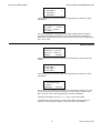
Using the arrow keys, move the cursor to
'NEXT' to display the next time program.
'TODAY' to make temporary changes to the current time program.
Confirm with ENTER.
If 'NEXT' has been selected, the screen will now display the next time program with
the switching point time of the first user address with its value/status and the current
day, date and time.
<2. time program>Init
MON 13.06. 10:27
to 12:00 ON
>TODAY
>NEXT
Using the arrow keys, move the cursor to 'NEXT'. Confirm with ENTER. The
following screen appears.
11
EN2B-0137GE51 R0902
PLANT KEY
EXCEL 50 USER GUIDE
<3. time program>Init
MON 13.06. 10:27
to 14:30 18 °C
>TODAY
>NEXT
Like the previous screen, this next screen displays the next time program with its
switching point, value/status and current day, date, and time.
TODAY Function
The 'TODAY' function allows the user to make an immediate, temporary change to
the switching time point or the value/status without affecting the original time
program. When using the 'TODAY' function, the data point must have value/status
and start and stop times assigned.
Important
The new start time will be within 24 hours of the current time. That means
for example, that a start time of 10:00 a.m. entered at 10:27 a.m. will
activate the temporary changes the next morning. The changed fields are
valid for only 24 hours; they are automatically deleted after the stop time
has been reached.
If 'TODAY' has been selected, the screen will now display the password entry
screen.
Please Enter
Your password
>****
>NEXT
NOTE: Changing a switching time point requires a level-2 or level-3 password.
Enter the level-2 or level-3 password using the arrow keys and the '+' and '–' key.
Confirm with ENTER. Using the arrow keys, move the cursor to 'NEXT' and confirm
with ENTER. The following screen appears.
<time prg.> Today
><user address>
↑
><user address>
1
><user address>
↓
Using the arrow keys, move the cursor to the user address to be changed
temporarily. Confirm with ENTER. The following screen appears.
<user address>
>09:00 to>12:00
Value: >ON
>SELECT
>BACK
Change the time or value/status using the '+' or '–' keys as required and use the
arrow keys to move from field to field. Confirm with ENTER.
EN2B-0137GE51 R0902
12
EXCEL 50 USER GUIDE
PLANT KEY
<user address>
>10:00 to>13:00
Value: >ON
>SELECT
>BACK
Once you have finished changing the values, use the arrow keys to move the cursor
to
'SELECT' to return to the selection list screen.
'BACK' to return to the default screen.
Confirm with ENTER.
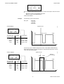
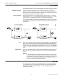
Example
A normal day cycle is shown below.
Day cycle:
06:00 ON
12:00 OFF
14:00 ON
20:00 OFF
Systime 10:27
0000095a
Screen displays:
AH01
MON 13.06. 10:27
TO: 12:00 ON
TODAY
NEXT
6:00
Time of the next
change of state
12:00
14:00
20:00
6:00
Status
Current time
ON
OFF
ON
OFF
10:27...11:59
12:00...13:59
14:00...19:59
20:00... 5:59
12:00 14:00
20:00
t
For this day cycle, a 'TODAY' entry from 10:00 to 13:00 with the status ON has
been made. The time of the next change has changed temporarily from 12:00 to
13:00. See the following figure.
Systime 10:27
AH01
MON 13.06. 10:27
TO: 13:00 ON
TODAY
NEXT
10:00
6:00
Time of the next
change of state
13:00
14:00
20:00
6:00
Status
Current time
ON
OFF
ON
OFF
10:27...12:59
13:00...13:59
14:00...19:59
20:00... 5:59
0000094a
Screen displays:
13:00
12:00 14:00
Active in
the next day
20:00
t
13
EN2B-0137GE51 R0902
PLANT KEY
EN2B-0137GE51 R0902
EXCEL 50 USER GUIDE
14
EXCEL 50 USER GUIDE
TIME PROGRAM KEY
Select the time program by pressing the 'Plant' fast-access key and changing the
screens with 'NEXT' until the time program name to be changed appears in the first
line of the screen.
Press the 'Time program' fast-access key to change time program settings. The
password entry screen will be displayed.
Please Enter
Your Password
>****
>NEXT
Changing the system time requires a level-2 or level-3 password. Refer to the
section 'Password Procedure' for help with password entry.
Enter the password. Confirm with ENTER.
Using the arrow keys, move the cursor to 'NEXT'. Confirm with ENTER.
15
EN2B-0137GE51 R0902
TIME PROGRAM KEY
EXCEL 50 USER GUIDE
System Time
The 'System Time' procedure is used to make changes to the time and the date
which the Excel 50 controller uses for its control programs. Use the 'Daylight saving'
function instead of the 'Date / Time' function to change the time in spring and
autumn.
>System Time
>Daily
>Weekly
>Annual
Using the arrow keys, move the cursor to the 'System Time' field. Confirm with
ENTER.
Setting Date and Time
System Time
>Date / Time
>Daylight Saving
Using the arrow keys, move the cursor to the 'Date / Time' field. Confirm with
ENTER. The following screen appears.
System Time
Date:>13.06.1997
Time:>10:28
>BACK
Using the arrow keys, move the cursor to the 'Date' or 'Time' field. Confirm with
ENTER.
System Time
Date:>23.06.1997
Time:>10:28
>BACK
If 'Date' is selected:
Set the date using the '+' or '–' keys. Use the arrow keys to move from field to field.
Confirm with ENTER. Use the arrow keys to move the cursor to 'BACK'. Confirm
with ENTER to return to the previous screen.
NOTE: The date must be entered in the format determined by the Engineering
Units: for example, 23. July 1997 must be entered as 23.07.1997 for
Europe and 07/23/1997 for the US. Press the CANCEL key to abort the
operation or to cancel an incorrect entry before ENTER has been pressed.
The value previously displayed will be restored.
EN2B-0137GE51 R0902
16
EXCEL 50 USER GUIDE
TIME PROGRAM KEY
System Time
Date:>23.06.1997
Time:>12:30
>BACK
If 'Time' is selected:
Set the time using the '+' or '–' keys. Use the arrow keys to move from field to field.
Confirm with ENTER. Use the CANCEL key to return to the previous screen.
NOTE: The time must be entered in the following format: HH:MM in 24-hour clock
format; for example: 9:30 a.m. must be 09:30 and 9:30 p.m. must be
21:30. Press the CANCEL key to abort the operation or to cancel an
incorrect entry before ENTER has been pressed. The value previously
displayed will be restored.
Daylight Saving
The actual dates on which daylight savings time starts and ends in a given year
must be changed every year.
System Time
>Date / Time
>Daylight Saving
Using the arrow keys, move the cursor to the 'Daylight Saving' field. Confirm with
ENTER. The following screen appears.
Daylight Saving
Start:>25.03
End :>26.09
>BACK
Enter the dates on which daylight savings time starts and ends for the current year
using the '+' or '–' keys. Move from field to field using the arrow keys. Confirm with
ENTER.
NOTE: Press the CANCEL key to abort the operation or to cancel an incorrect
entry before ENTER has been pressed. The value previously displayed will
be restored.
Daylight Saving
Start:>27.03
End :>26.09
>BACK
Using the arrow keys, move the cursor to 'BACK'. Confirm with ENTER to return to
the start screen of the time program.
17
EN2B-0137GE51 R0902
TIME PROGRAM KEY
EXCEL 50 USER GUIDE
Daily Program
>System Time
>Daily
>Weekly
>Annual
Using the arrow keys, move the cursor to the 'Daily' field in the main screen.
Confirm with ENTER.
NOTE: The 'Daily' program contains daily time programs.
EN2B-0137GE51 R0902
18
EXCEL 50 USER GUIDE
TIME PROGRAM KEY
AHU1
Daily
>MODIFY >NEW
>DELETE >COPY
Using the arrow keys, move the cursor to
'MODIFY' to modify the daily time programs.
'NEW' to create a new daily time program.
'DELETE' to delete a daily time program.
'COPY' to copy a daily time program to another.
Confirm with ENTER.
Modifying a Daily Time Program
AHU1
Modify
>Workday
>Weekend
>Shutdown
↑
1
↓
Using the arrow keys, move the cursor to the daily time program you wish to modify
and confirm with ENTER.
Creating a New Switching Point
AHU1
>NEW
>06:00 <user addr.>↑
>06:00 <user addr.>1
>06:30 <user addr.>↓
Using the arrow keys, move the cursor to 'NEW'. Confirm with ENTER.
AHU1
Workday
><user addr.>
↑
><user addr.>
1
><user addr.>
↓
Using the arrow keys, move the cursor to the user address to which the new
switching point should belong.
AHU1
sp01
>06:01 >20.0 °C
Opt: >OFF
>OK
Modify the time, the value or the optimize flag of the new switching point using the
'+' or '–' keys (The optimize flag can be set to ON only if the user address is suitable
for optimization).
Use the arrow keys to move from field to field. Confirm with ENTER.
Using the arrow keys, move the cursor to 'OK' and confirm with ENTER to add the
new switching point to the current time program.
19
EN2B-0137GE51 R0902
TIME PROGRAM KEY
EXCEL 50 USER GUIDE
Modifying or Deleting a Switching Point
AHU1
>NEW
>06:00 <user addr.>↑
>06:00 <user addr.>1
>06:00 <user addr.>↓
Using the arrow keys, move the cursor to the switching point you wish to modify or
delete. Confirm with ENTER.
AHU1
<user addr.>
>06:00 >20.0°C
Opt: >OFF
>DELETE
Modify the time, the value, or the optimize flag of the switching point. Using the
arrow keys, move the cursor to the field you wish to change. Confirm with ENTER.
Use the '+' and '–' keys to change the field content. If you wish to delete the
switching point, use the arrow keys to move the cursor to the 'DELETE' field and
confirm with ENTER.
AHU1
<user addr.>
Really delete
switchp 06:00?
>YES
>NO
If you are sure that you wish to delete the switching point, use the arrow keys to
move the cursor to 'YES' and confirm with ENTER. If you do not wish to delete the
switching point, use the arrow keys to move the cursor to 'NO' and confirm with
ENTER. In the latter case, you will escape to the previous screen without deleting
the switching point.
Creating a New Daily Time Program
Using the arrow keys, move the cursor to 'YES'. Confirm with ENTER.
AHU1
new daily prog.
DP 1
>MODIFY >BACK
The newly created daily time program is issued the name DP and the lowest
number which is not assigned to a daily time program.
Using the arrow keys, move the cursor to
'MODIFY' to go to the 'Modify daily time program' sequence.
'BACK' to return to the 'Time program' menu screen.
Confirm with ENTER.
EN2B-0137GE51 R0902
20
EXCEL 50 USER GUIDE
TIME PROGRAM KEY
Deleting a Daily Time Program
AHU1
Delete
>Workday
↑
>Weekend
1
>Shutdown
↓
Using the arrow keys, move the cursor to the daily time program to be deleted.
Confirm with ENTER.
AHU1
Really delete
Shutdown ?
>YES
>NO
Using the arrow keys, move the cursor to 'YES' to delete the daily time program or
'NO' to keep it. Confirm with ENTER.
Copying a Daily Time Program
A daily time program can be copied in order to create a new daily time program,
which should be similar to an already existing daily time program.
AHU1
Copy
>Workday
>Weekend
>Shutdown
↑
1
↓
Using the arrow keys, move the cursor to the daily time program to be copied.
Confirm with ENTER.
AHU1
Weekend
copied to
DP_2
>BACK
The copy of the daily time program is issued the name DP and the lowest number
which is not assigned to a daily time program.
Weekly Program
>System Time
>Daily
>Weekly
>Annual
Using the arrow keys, move the cursor to the 'Weekly' field. Confirm with ENTER.
21
EN2B-0137GE51 R0902
TIME PROGRAM KEY
EXCEL 50 USER GUIDE
AHU1
Weekly
>MON Workday
↑
>TUE Workday
1
>WED Workday
↓
A daily time program is assigned to each day of the week in the weekly time
program. To assign another daily time program to a day of the week, use the arrow
keys to move the cursor to this day. Confirm with ENTER.
AHU1
>Workday
>Weekend
>DP 1
MON
↑
1
↓
Using the arrow keys, move the cursor to the daily time program to be assigned to
the day of the week displayed in the upper right corner. Confirm with ENTER.
AHU1
MON
really assign
Weekend
?
>YES
>NO
Using the arrow keys, move the cursor to 'YES' to assign the daily time program to
the weekday or 'NO' to escape from this screen without any changes. Confirm with
ENTER.
Annual Program
System Time
>Daily
>Weekly
>Annual
Using the arrow keys, move the cursor to the 'Annual' field. Confirm with ENTER.
AHU1
Annual
display from
>23.06.1997
>NEXT
The annual program will be displayed from the date shown in this screen. The
default date is the current date. Using the arrow keys, move the cursor to the date
field. Confirm with ENTER.
Use the '+' or '–' keys to change the date and move to the next digit using the right
arrow key. Confirm with ENTER.
Using the arrow keys, move the cursor to 'NEXT'. Confirm with ENTER.
AHU1
Workday
From: 22.12.1997
To:
07.01.1998
>CHANGE
>NEXT
EN2B-0137GE51 R0902
22
EXCEL 50 USER GUIDE
TIME PROGRAM KEY
In this screen, the name of the daily time program which is assigned to the period is
shown.
If there is no daily time program assigned to the annual schedule, the following
screen appears:
AHU1
********
FRI 16.05.1997
FRI 16.05.1997
>CHANGE
>NEXT
Regardless of which screen appears, use the arrow keys to move the cursor to
'NEXT' to display the next period a daily time program is assigned to.
'CHANGE' to change the settings for the shown period.
Confirm with ENTER.
AHU1
Workday
From:>22.12.1997
To: >07.01.1998
>REMOVE >ASSIGN
If 'CHANGE' has been selected, this screen will be displayed. Using the arrow keys,
move the cursor to the date fields you wish to change. Confirm with ENTER. Use the
'+' and '–' keys to change the start and end dates.
Using the arrow keys, move the cursor to
'ASSIGN' to assign another daily time program to the period.
'REMOVE' to remove the daily time program shown in the first line of the
screen from the period.
Confirm with ENTER.
AHU1
SELECT:
>Workday
↑
>Weekend
1
>DP 4
↓
If 'ASSIGN' has been selected, this screen will appear. Using the arrow keys, move
the cursor to a daily time program to assign it to the previously entered period of
time. Confirm with ENTER.
AHU1
really remove
entry?
>YES
>NO
If 'REMOVE' has been selected, this screen will appear. Using the arrow keys,
move the cursor to 'YES' to remove the daily time program from the period. Confirm
with ENTER.
23
EN2B-0137GE51 R0902
TIME PROGRAM KEY
EN2B-0137GE51 R0902
EXCEL 50 USER GUIDE
24
EXCEL 50 USER GUIDE
DATA POINTS / PARAMETERS KEY
25
EN2B-0137GE51 R0902
EXCEL 50 USER GUIDE
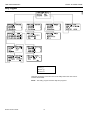
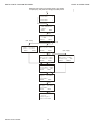
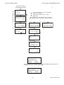
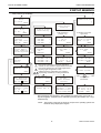
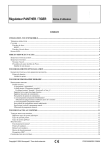
Sequence of screens for analog input (AI), analog
output (AO), and pseudo analog (PA) data points
*
<user addr.>
<user addr.>
<user addr.>
<user addr.>
↑
1
↓
<user addr.>
<user defined text>
<value>
AUTO
NEXT
(AO, only)
<user addr.>
Suppress Alarm
YES
BACK
NEXT
(AI, PA)
Time to
Open
0.0sec
Close 0.0sec
BACK
NEXT
Min Lim2 <value>
Min Lim1 <value>
BACK
NEXT
(PA, only)
(AI, only)
Min Lim2
Min Lim1
S.Offset
BACK
<value>
<value>
<value>
NEXT
<user addr.>
Tech Addr: <value>
Trend log: YES
BACK
NEXT
<user addr.>
Input: <NV index>
<nvi name>
BACK
NEXT
<user addr.>
Output: <NV index>
<nvo name>
BACK
NEXT
Trend Hysteresis
1.0 Pct
Trend Cycle:
0000 min BACK
EN2B-0137GE51 R0902
26
Min Lim2 <value>
Min Lim1 <value>
Trend log: YES
BACK
NEXT
0000125b
DATA POINTS / PARAMETERS KEY
DATA POINTS / PARAMETERS KEY
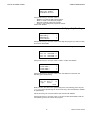
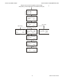
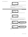
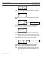
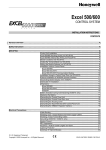
Sequence of screens for digital input (DI), digital
output (DO), pseudo digital (PD), and totalizer points (PI)
*
<user addr.>
<user addr.>
<user addr.>
<user addr.>
0000126b
EXCEL 50 USER GUIDE
↑
1
↓
<user addr.>
<user defined text>
<value>
AUTO
NEXT
<user addr.>
Suppress Alarm
YES
BACK
NEXT
(PD, only)
(PI, only)
(DI, DO)
<user addr.>
Trend log:
BACK
YES
NEXT
<user addr.>
Tech Addr: <value>
Trend log: YES
BACK
NEXT
<user addr.>
Tech Addr: <value>
Trend log: YES
BACK
<user addr.>
Input: <NV index>
<nvi name>
BACK
NEXT
<user addr.>
Output: <NV index>
<nvo name>
BACK
NEXT
<user addr.>
Normally Closed
YES
BACK
27
EN2B-0137GE51 R0902
EXCEL 50 USER GUIDE
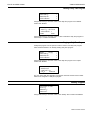
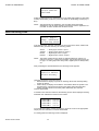
Sequence of screens for remote
analog (RA) and remote digital (RD) points
0000127b
DATA POINTS / PARAMETERS KEY
*
<user addr.>
<user addr.>
<user addr.>
<user addr.>
↑
1
↓
<user addr.>
<user defined text>
<value>
AUTO
NEXT
(RA and RD)
(configurable applications, only)
<user addr.>
Suppress Alarm
YES
BACK
NEXT
<user addr.>
RemoteController
Number:
0
BACK
(RA, only)
(CARE applications, only)
<user addr.>
Broadcast Hyst..
<value>
BACK
Press the 'Data points / parameters' fast-access key to get access to information on
physical, remote and pseudo user addresses, parameters, system data, and the
DDC program cycle time.
The password entry screen will be displayed.
Please Enter
Your Password
>****
>NEXT
Access to information on user addresses, parameters, system data, and the DDC
program cycle time requires a level-2 or level-3 password. Refer to the section
'Password Procedure' for help with password entry.
Enter the password. Confirm with ENTER.
Using the arrow keys, move the cursor to 'NEXT'. Confirm with ENTER.
Data Points
>Analog Input
>Analog Output
>Digital Input
>NEXT
Using the arrow keys, move the cursor to
'Analog Input', 'Analog Output', or 'Digital Input' to go into the 'Data points'
sequence.
'NEXT' to proceed to the next screen.
EN2B-0137GE51 R0902
28
EXCEL 50 USER GUIDE
DATA POINTS / PARAMETERS KEY
Confirm with ENTER.
>Digital Output
>Totalizer
>Hours Run
>BACK
>NEXT
Using the arrow keys, move the cursor to
'Digital Output' or 'Totalizer' to go into the 'Data points' sequence.
'Hours run' to go to the 'Hours run' screen.
'NEXT' to proceed to the next screen.
'BACK' to return to the previous screen.
Confirm with ENTER.
>M-Bus Data
>Pseudo Analog
>Pseudo Digital
>BACK
>NEXT
Using the arrow keys, move the cursor to
'M-Bus Data', 'Pseudo Analog', or 'Pseudo Digital' to go into the 'Data Points'
sequence. M-Bus Data will show only special pseudo points related to the
Meter Bus. These special points also appear under the Pseudo Analog and
Pseudo Digital.
'NEXT' to proceed to the next screen.
'BACK' to return to the previous screen.
Confirm with ENTER.
>Remote Analog
>Remote Digital
>Manual Operat.
>BACK
>NEXT
Using the arrow keys, move the cursor to
'Remote Analog' or 'Remote Digital' to go into the 'Remote points' sequence.
'Manual Operat.' to go to the 'Manual operation' screen.
'NEXT' to proceed to the next screen.
Confirm with ENTER. The sequence proceeds to the Parameters sequence
discussed separately in a later section.
Data Points Sequence
The 'Data Points' sequence will change depending upon the type of data point
selected. Only the complete sequence for analog input points will be shown here as
an example. Features unique to other data point types will be shown afterwards.
Selecting one of the data point types will display the first screen of the 'Data Points'
sequence.
><user addr.>
><user addr.>
><user addr.>
><user addr.>
↑
1
↓
Using the arrow keys, move the cursor to the appropriate data point. Confirm with
ENTER.
29
EN2B-0137GE51 R0902
DATA POINTS / PARAMETERS KEY
EXCEL 50 USER GUIDE
<user addr.>
<user defined text>
><value>
>AUTO
>NEXT
In this screen, the operating mode field can be changed from 'AUTO' to 'MANUAL'
(and vice versa) and the setpoint value/status can be changed. Using the arrow
keys, move the cursor to the appropriate field. Confirm with ENTER.
Change the value/status using the '+' or '–' keys. Confirm with ENTER.
If the operating mode is changed, an alarm screen with the message 'Manual
operation' or 'Auto operation' appears. Confirm the alarm with CANCEL.
Using the arrow keys, move the cursor to 'NEXT'. Confirm with ENTER.
<user addr.>
Suppress Alarm
>YES
>BACK
>NEXT
The attribute "Suppress Alarm" of the user address can be changed from 'YES' to
'NO' and vice versa. Using the arrow keys, move the cursor to the appropriate field.
Confirm with ENTER.
Change the status using the '+' or '–' keys. Confirm with ENTER.
Using the arrow keys, move the cursor to 'NEXT'. Confirm with ENTER.
Min lim2><value>
Min lim1><value>
>BACK
>NEXT
This and the next screen will be shown only for analog input and pseudo analog
data points. Change the value of the attributes "Min Alarm Limit" and "Max Alarm
Limit" using the '+' and '–' keys. Confirm with ENTER.
Using the arrow keys, move the cursor to 'NEXT'. Confirm with ENTER.
Max lim1><value>
Max lim2><value>
S.Offset><value>
>BACK
>NEXT
Change the value of the attributes "Min Alarm Limit", "Max Alarm Limit", and
"Sensor Offset" using the '+' and '–' keys. Confirm with ENTER.
Using the arrow keys, move the cursor to 'NEXT'. Confirm with ENTER.
<user addr.>
Tech Addr <value>
Trend log: YES
>BACK
>NEXT
This screen displays the technical address of the data point. The technical address
is a number with six digits in pairs of two and stands for the following data:
EN2B-0137GE51 R0902
30
EXCEL 50 USER GUIDE
DATA POINTS / PARAMETERS KEY
XX XX XX
Physical point address
Board number
Controller number
For an explanation of Board Number, see section "Data Point Wiring Check". To
enable trend logging for this data point, use the arrow keys to move the cursor to
the appropriate field. Confirm with ENTER. Change the value/status using the '+' or
'-' keys. Confirm with ENTER.
Using the arrow keys, move the cursor to 'NEXT'. Confirm with ENTER. Except in
the case of Remote Analog points, the following screen appears:
<user addr.>
Input: <NV index>
<nvi name>
>BACK
>NEXT
This screen shows the mapping of data points to network variables transmitted on
the LONW ORKS bus. If no network variables have been mapped, the index and NV
name fields will be blank. This screen appears also for outputs, with NV index for
the output and nvo name displayed.
In the case of Remote Analog points only, the following screen appears:
Trend hysteresis
1.0 Pct
Trend Cycle:
0000 min >BACK
To change the attributes "Trend Hysteresis" or "Trend Cycle", use the arrow keys to
move the cursor to the appropriate field. Confirm with ENTER.
Change the value/status using the '+' or '–' keys.
NOTE: If "Trend Cycle" is set to anything other than 0000, time-based trending is
enabled. If "Trend Cycle" is set to 0000, then value-hysteresis trending is
enabled using the percent value show for "Trend Hysteresis".
Digital Points
This screen is visible only for digital points and shows the relationship between the
physical state of a digital point and its logical status.
<user addr.>
Normally Closed
>YES
>BACK
>NEXT
The attribute "Normally Open/Normally Closed" of the user address can be changed
from 'YES' to 'NO' and vice versa. Using the arrow keys, move the cursor to the
appropriate field. Confirm with ENTER.
Using the arrow keys, move the cursor to 'NEXT'. Confirm with ENTER.
Remote Points
This screen is visible only for remote points and shows the controller number of a
remote point.
31
EN2B-0137GE51 R0902
DATA POINTS / PARAMETERS KEY
EXCEL 50 USER GUIDE
<user addr.>
RemoteController
Number:
0
>BACK
>NEXT
Change the controller number using the '+' and '–' keys. Confirm with ENTER. In the
case of points which the controller receives from other controllers on the C-Bus, the
controller number of the source of the point must be entered. For points that the
controller is the source of, the default value of 0 is required.
Using the arrow keys, move the cursor to 'NEXT'. Confirm with ENTER.
Analog Outputs
This screen is visible only for analog outputs and shows - for example - the time an
actuator needs to open and close a valve.
Time to
Open
Close
>BACK
0.0sec
0.0sec
>NEXT
Change the values using the '+' and '–' keys. Confirm with ENTER.
Using the arrow keys, move the cursor to 'NEXT'. Confirm with ENTER.
CARE Applications
For applications created in CARE, the sequence for Remote Digital points ends with
the second screen, showing user address, state, and mode. The sequence for
Remote Analog points proceeds to the following one:
<user addr.>
Broadcast Hyst.:
<value>
>BACK
This screen allows you to change the attribute "Broadcast Hysteresis". This attribute
is available for remote analog data points in CARE applications (not applicable to
configurable applications). "Broadcast Hysteresis" prevents new values from being
broadcast to other controllers unless the data point value changes (positively or
negatively) at least by the amount specified in this screen. Using the arrow keys,
move the cursor to the appropriate field. Confirm with ENTER.
Change the value/status using the '+' or '–' keys. Confirm with ENTER.
Hours Run
Digital Output
Totalizer
>Hours Run
BACK
NEXT
Using the arrow keys, move the cursor to the 'Hours Run' field. Confirm with
ENTER.
EN2B-0137GE51 R0902
32
EXCEL 50 USER GUIDE
DATA POINTS / PARAMETERS KEY
><user addr.>
<user addr.>
<user addr.>
<user addr.>
↑
1
↓
Using the arrow keys, move the cursor to the appropriate user address. Confirm
with ENTER.
<user addr.>
><value>
hours
Switch <status>
><value>
The screen displays the total running hours logged together with the number of
times the device has been switched on. If you have accessed the 'Data points /
parameters' procedure with the level-3 password, the values can be changed using
the '+' and '–' keys.
Manual Operation
>Remote Analog
>Remote Digital
>Manual Operat.
>BACK
>NEXT
Using the arrow keys, move the cursor to the 'Manual Operat.' field. Confirm with
ENTER.
><user addr.>
><user addr.>
><user addr.>
><user addr.>
↑
1
↓
Using the arrow keys, move the cursor to the appropriate user address. Confirm
with ENTER.
<user addr.>
<user defined text>
><value>
>MANUAL
>BACK
In this screen, the operating mode field can be changed from 'MANUAL' to 'AUTO'
(and vice versa) and the setpoint value/status can be changed. Using the arrow
keys, move the cursor to the appropriate field. Confirm with ENTER.
Change the value/status using the '+' or '–' keys. Confirm with ENTER.
If the operating mode is changed, an alarm screen with the message 'Manual
operation' or 'Auto operation' appears. Confirm the alarm with CANCEL.
33
EN2B-0137GE51 R0902
DATA POINTS / PARAMETERS KEY
EXCEL 50 USER GUIDE
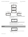
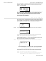
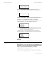
0000122d
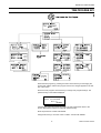
Parameters
Points in Trend
Parameters
System Info
BACK
NEXT
Separate overview for
Hardware Interface
Configuration screens.
HW-Interf. Cfg.
DDC-Times
Buswide Access
BACK
NEXT
List:
000
Number:
001
Val:
20.00
BACK
5
1
1
<user addr.>
<value>
Trend log
Flash EPROM
SAVE APPLIC.
ERASE FLASH
SHOW APPLIC.
<user addr.>
<user addr.>
<user addr.>
<user addr.>
Buswide Access
LOGIN LOGOFF
Remote Alarms
ON
OFF
Erasing Flash
Please wait!
<user addr.> <unit>↑
<time> <value> 1
<time> <value>
<time> <value> ↓
<name>
NEXT
Fixed
<app.>
<app.>
<app.>
Config.
NEXT
C1<code>C2<code>
C3<code>C4<code>
C5<code>C6<code>
Config.
NEXT
5
5
C7<code>C8<code>
Tool Ident. Data
Name: <tool name>
Vers: <vers. no.>
BACK
NEXT
Tool Ident. Data
User Name:
<user name>
BACK
NEXT
EN2B-0137GE51 R0902
Applic.
<date>
↑
1
<date>
↓
<date>
User ID:
<user ID number>
5
NEXT
5
<val.>↑
<val.>1
<val.>
<val.>↓
3
4
Burning Flash
Please wait!
2
1
↓
ON
BACK
BACK
Burn Date:
<date>
<time>
BACK
NEXT
BACK
1
Trend Buffer
Flash EPROM
Prj./Appl. Name:
<project name>
<applic. name>
BACK
NEXT
Applicat.
<version>
↑
DDC-Times
Exec. Time:1.72
Cycl. Time:3.00
BACK
Controller Name:
<controller name>
Softw.:V2.00.00
BACK
NEXT
5
><user addr.>
<user addr.>
<user addr.>
<user addr.>
Op. Seq. Rev.
AMA: <rev. no.>
ATX: <rev. no.>
BACK
34
Remote Login
<controller>
<controller>
<controller>
↑
1
↓
<1. time program>
MON 13.06. 10:27
TO: 20:30 20°C
TODAY
NEXT
1
This screen appears only with configurable
application controllers.
2
This screen appears only for certain
applications requiring eight application codes.
3
This screen belongs to the local controller
again after logging off from the remote controller.
4
This screen belongs to the chosen remote
controller.
5
This screen appears only with freely
programmable controllers.
EXCEL 50 USER GUIDE
DATA POINTS / PARAMETERS KEY
0000141
Hardware Interface
Configuration screens
HW-Interf. Cfg.
>C-Bus
↑
Lon-Bus
1
B-Port
↓
1
This screen appears only with configurable
application controllers.
2
These screens appear only for CARE
applications.
4
3
B-Port Config.
Baudrate:> 9600
3
4
Additional options (“Meter Bus” and “Modem”,
respectively) viewable by scrolling downwards.
BACK
LON-Bus Config.
Ctr. Neuron ID:
000239026601
>BACK
Modem Config.
Baudrate: > 9600
GSM PIN ********
Reset Modm NEXT
C-Bus Config.
Baudrate:> 38400
Ctr. No : 4
Bus ID:
BACK
M-Bus Config.
Baudrate: <bdrate>
Point Assgnmt.
BACK
Appl. Mem. Size:
128 KB
Rem. Trend Buf.:
1400 Entr. BACK
HM1 - 1
HM2 - 1
WM1 - 1
1
2
<user addr.>
<user addr.>
<user addr.>
<user addr.>
<no.>↑
<no.>1
<no.>
<no.>↓
<user addr.>
M-Bus No.: <no.>
2
BACK
>Points in Trend
>Parameters
>System Info
>BACK
>NEXT
Using the arrow keys, move the cursor to 'NEXT' to display the second screen of
the 'Parameters' menu. Confirm with ENTER.
>HW-Interf. Cfg.
>DDC-Times
>Buswide Access
>BACK
>NEXT
35
EN2B-0137GE51 R0902
DATA POINTS / PARAMETERS KEY
EXCEL 50 USER GUIDE
Using the arrow keys, move the cursor to 'NEXT' to display the third screen of the
'Parameters' menu. Confirm with ENTER.
>Trend Buffer
>Flash EPROM >
>BACK
Points in Trend
>Points in Trend
>Parameters
>System Info
>BACK
>NEXT
Using the arrow keys, move the cursor to the 'Points in Trend' field. Confirm with
ENTER.
><user addr.>
><user addr.>
><user addr.>
><user addr.>
↑
1
↓
Using the arrow keys, move the cursor to the appropriate data point. Confirm with
ENTER.
<user addr.>
<value>
Trend Log
ON
>BACK
To enable/disable trend logging for this data point, use the arrow keys to move the
cursor to the appropriate field. Confirm with ENTER.
Change the value/status using the '+' or '–' keys. Confirm with ENTER. Using the
arrow keys, move the cursor to 'BACK'. Confirm with ENTER to return to the list
under 'Points in Trend'.
Parameter List
>Points in Trend
>Parameters
>System Info
>BACK
>NEXT
To view or change control parameters of devices connected to the controller, use
the arrow keys to move the cursor to the 'Parameters' field in the first screen of the
parameters sequence. Confirm with ENTER. Changing parameters requires a level3 password.
EN2B-0137GE51 R0902
36
EXCEL 50 USER GUIDE
DATA POINTS / PARAMETERS KEY
List
000
NO.
001
Val.>20.00
°C
>BACK
To change the parameter value, use the arrow keys to move the cursor to the value
field. Confirm with ENTER.
Use the '+' or '–' keys to change the value. Confirm with ENTER.
Using the arrow keys, move the cursor to 'BACK'. Confirm with ENTER to return to
the parameter list screen.
System Information
>Points in Trend
>Parameters
>System Info
>BACK
>NEXT
Using the arrow keys, move the cursor to the 'System Info' field. Confirm with
ENTER.
Controller Name:
<controller name>
Softw.:V 2.00.00
>BACK
>NEXT
Using the arrow keys, move the cursor to the controller name field. Confirm with
ENTER.
Using the arrow keys, move the cursor to 'NEXT'. Confirm with ENTER to proceed to
the next screen (which depends upon the type of application module used).
Prj./Appl. Name
<project name>
<application name>
>BACK
>NEXT
This screen does not appear in
configurable applications.
This screen displays the name of the current project and application. 'NEXT' is
preselected to move to the burn date screen. Confirm with ENTER.
Burn Date:
<burn date>
<burn time>
>BACK
>NEXT
This screen does not appear in
configurable applications.
This screen displays the burn date and time of the current project and application.
'NEXT' is preselected to move to the application version screen. Confirm with
ENTER.
37
EN2B-0137GE51 R0902
DATA POINTS / PARAMETERS KEY
EXCEL 50 USER GUIDE
Applicat. <name>
<version>
>BACK
This screen appears in configurable applications only.
>NEXT
This screen displays the name of the current application and its version number.
'NEXT' is preselected to move to the configuration codes screen. Confirm with
ENTER.
Config.
C1<code>
C3<code>
C5<code>
>NEXT
C2<code>
C4<code>
C6<code>
This screen appears in configurable applications only.
In this screen, the codes of the configurable application can be viewed.
NOTE: Not all applications have 6 configuration code numbers. Applications with
eight configuration codes have two on a second screen as shown below.
Second screen:
CONFIG.
>NEXT
C7<code>
C8<code>
This screen appears in configurable applications only.
IMPORTANT
After performing a RESET, all data in RAM and the configuration codes
are lost.
To change the codes perform a RESET (press the down arrow and the minus key
simultaneously). The codes can then be changed In the start-up sequence.
'NEXT' is preselected to move to the Tool Information screen. Confirm with ENTER.
Tool Ident. Data
Name:<tool name>
Vers:<version number>
>BACK
>NEXT
This screen displays the name and version number of the tool used to create the
current application. 'NEXT' is preselected to move to the User Name screen.
Confirm with ENTER.
Tool Ident. Data
User Name:
<user name>
>BACK
>NEXT
This screen displays the user name for the tool used to create the current
application. 'NEXT' is preselected to move to the 'User ID' screen. Confirm with
ENTER.
User ID:
<user ID number>
>NEXT
EN2B-0137GE51 R0902
38
EXCEL 50 USER GUIDE
DATA POINTS / PARAMETERS KEY
This screen displays the user license number for the tool used to create the current
application. 'NEXT' is preselected to move to the Operating Sequence Revision
screen. Confirm with ENTER.
Op. Seq. Rev.
AMA: <revision number>
ATX: <revision number>
>BACK
This screen displays the revision numbers for the AMA and ATX files used to create
the operating sequence. Asterisks will appear before and after the AMA revision
number if the AMA or ADS files have been changed before the compilation.
Asterisks will also appear before and after the ATX revision number if the ATX file
has been changed before compilation. 'BACK' is preselected to move to the
previous screen. Confirm with ENTER.
Hardware Interface Configuration
The following sequence will depend upon the specific hardware interfaces featured
on the controller. The list box will contain a combination of the following options: Bport (serial port), C-bus, LON-bus, M-Bus, or Modem (RS232 serial port).
HW-Interf. Cfg.
B-Port
↑
C-Bus
1
LON-Bus
↓
B-Port
Using the arrow keys, move the cursor to the 'B-Port' field. Confirm with ENTER.
B-Port Config.
Baudrate<bdrate>
>BACK
Using the arrow keys, move the cursor to the value field. Confirm with ENTER.
NOTE: Changing the baud rates requires a level-2 password.
Change the values using the '+' or '–' keys. Confirm with ENTER. Using the arrow
keys, move the cursor to ‘BACK’ and confirm with ENTER.
C-Bus
Using the arrow keys, move the cursor to the 'C-Bus' field. Confirm with ENTER.
C-Bus Config.
Baudrate:<bdrate>
Contr.No:>1
Bus ID
□ >BACK
NOTE: If you set the bus ID to a non-zero value, the C-bus baudrate will be
immediately disabled (i.e. it is then no longer editable). See also
section "LONW ORKS Bus" below.
Using the arrow keys, move the cursor to the value field. Confirm with ENTER.
NOTE: Changing the baud rates requires a level-2 password.
NOTE: To provide compatibility with the PC-based XI584 operator and service
software, this C-Bus screen may appear even for controllers with
39
EN2B-0137GE51 R0902
DATA POINTS / PARAMETERS KEY
EXCEL 50 USER GUIDE
application modules that do not have a C-Bus connection. This screen will
not appear for controllers using the XD50E application module, which
does not allow downloads.
Change the values using the '+' or '–' keys. Confirm with ENTER. To change the
controller number, repeat previous steps. Using the arrow keys, move the cursor to
‘BACK’ and confirm with ENTER.
LONWORKS Bus
Using the arrow keys, move the cursor to the 'LON-Bus' field. Confirm with ENTER.
LON-Bus Config.
Contr. Neuron ID
<neuron ID no.>
>BACK
This screen displays the unique ID number of the Neuron processor. Using the
arrow keys, move the cursor to ‘BACK’ and confirm with ENTER.
Modem
Using the arrow keys, move the cursor to the 'Modem' field. Confirm with ENTER.
Modem Config.
Baudrate:<bdrate>
GSM PIN:********
Reset Modm >NEXT
This screen appears only when
modem communication is enabled.
Using the arrow keys, move the cursor to the value field. Confirm with ENTER.
NOTE: Changing the baud rates requires a level-2 password.
Change the values using the '+' or '–' keys. Confirm with ENTER.
To enter the password for GSM communication, use the arrow keys to move to the
‘GSM PIN’ field. Press ENTER to enter the field. Press the '+' or '–' keys to
increment/decrement the digit. Press ENTER to confirm the digit. Use the left or
right arrow key to move to the next digit. When all digits are entered, press ENTER
twice to confirm the PIN.
IMPORTANT
The GSM PIN must be entered right justified.
The modem baud rate must be set to 9600 for GSM communication to
work.
Using the arrow keys, move the cursor to 'Reset Modem' to reset the modem to its
factory setting (insure that the modem is connected). Confirm with ENTER.
IMPORTANT
Resetting the modem will restore the factory defaults and erase any
custom initialization.
Using the arrow keys, move the cursor to ‘NEXT’ and confirm with ENTER.
Appl. Mem. Size
128 KB
Rem. Trend Buf.
104 Entr. >BACK
This screen appears only when
modem communication is enabled.
This screen displays the size of the adjustable remote trend buffer. The number of
entries (trend samples) that can be stored in the buffer for Remote Building Central
A is determined by a calculation by the controller based upon the Application
Memory Size entered in the start-up sequence. The values shown can be changed
EN2B-0137GE51 R0902
40
EXCEL 50 USER GUIDE
DATA POINTS / PARAMETERS KEY
only by resetting the controller and entering a new value for Appl. Mem. Size in the
start-up sequence.
NOTE: Firmware V2.03.01 or later and CARE V2.02.00 or later enables the controller to run RACL partly from the Flash EPROM. Thus, the application
memory calculation is different compared to older versions. This has to be
considered during start up once you enter the application memory size.
1. CARE V2.02.00 or later:
The maximum application size is 128 Kbytes (128 Kbytes flash
memory). Enter the application size calculated by CARE.
2. CARE versions before V2.02.00 without modem:
The maximum application size calculated by the old CARE is 113
Kbytes because the complete application including RACL runs from
the RAM. The controller will not run if the application is bigger. You
need to use CARE at least V2.02.00 if your applications require more
than 113 Kbytes.
Applications bigger than 113 Kbytes without modem will not run
from the flash memory after firmware download of OS V2.03.01 if
they were done with CARE versions before V2.02.00.
3. CARE versions before V2.02.00 with modem:
The maximum application size calculated by the old CARE is 100
Kbytes. The controller will not run if the application is bigger. For the
calculation of the trend buffer you need to enter 28 Kbytes plus the
application size calculated by the old CARE version, e.g., CARE
before V2.02.00 calculated 98 Kbytes, thus you will enter 126 Kbytes
(98 Kbytes + 28 Kbytes) on the MMI of the controller.
We strongly recommend using CARE V2.02.00 or later if you use
modem communication. This will allow for applications with up to 128
Kbytes (128 Kbytes flash memory).
Applications bigger than 100 Kbytes with modem will not run
from the flash memory after firmware download of OS V2.03.01 if
they were done with CARE versions before V2.02.00.
4. Configurable applications:
Always enter 128 Kbyte for the application memory size.
Using the arrow keys, move the cursor to ‘BACK’ and confirm with ENTER.
M-Bus
Using the arrow keys, move the cursor to the 'M-Bus' field. Confirm with ENTER.
M-Bus Config.
Baudrate:<bdrate>
Point Assgnmt.
>BACK
Using the arrow keys, move the cursor to the value field. Confirm with ENTER.
NOTE: Changing the baud rates requires a level-2 password.
Change the values using the '+' or '–' keys. Confirm with ENTER.
Using the arrow keys, move the cursor to the ‘Point Assgnmt.’ field. Confirm with
ENTER.
For configurable applications the following screen will appear:
HM1 - 1=
HM2 - 1
WM1 - 1
This screen appears only with
configurable applications.
This screen displays the bus numbers for up to three heat meters and/or up to two
water meters on the Meter Bus (up to max. 3 meters in total). A value of 0 or lower
41
EN2B-0137GE51 R0902
DATA POINTS / PARAMETERS KEY
EXCEL 50 USER GUIDE
(-1 default) means no device is connected. Using the arrow keys, move the cursor
to the appropriate bus number field. Confirm with ENTER.
Use the '+' or '–' keys to change the value. Confirm with ENTER.
To return to the previous screen, use the arrow keys to move the cursor to
CANCEL. Confirm with ENTER.
In the case of CARE applications, the following screen appears following the ‘M-Bus
Config.’ screen:
<user address><no.> ↑
<user address><no.> 1
<user address><no.>
<user address><no.> ↓
This screen appears only with nonconfigurable applications.
This screen displays the user address and Meter Bus device number assigned to it.
To change the Meter Bus device number, use the arrow keys to move the cursor to
the appropriate user address and confirm with ENTER. The following screen
appears:
<user address>
M-Bus Nr: <no.>
>BACK
Using the arrow keys, move the cursor to the value field to set the device number of
the Meter Bus. Confirm with ENTER.
Use the '+' or '–' keys to change the value. Confirm with ENTER. Using the arrow
keys, move the cursor to ‘BACK’ and confirm with ENTER.
DDC Program Cycle Times
>HW-Interf. Cfg.
>DDC-Times
>Buswide Access
>BACK
>NEXT
Using the arrow keys, move the cursor to the 'DDC-Times' field. Confirm with
ENTER.
DDC-Times
Exec.Time: 1.72
Cycl.Time:>3.00
>BACK
This screen displays the RACL cycle time and execution time in seconds. The cycle
time can be changed to optimize the system performance. Changing the cycle time
requires a level-3 password. Using the arrow keys, move the cursor to the 'Cycl.
time' field. Confirm with ENTER.
Use the '+' or '–' keys to change the value. Confirm with ENTER.
Using the arrow keys, move the cursor to 'BACK'. Confirm with ENTER.
EN2B-0137GE51 R0902
42
EXCEL 50 USER GUIDE
DATA POINTS / PARAMETERS KEY
Buswide Access
>HW-Interf. Cfg.
>DDC-Times
>Buswide Access
>BACK
>NEXT
The 'Buswide Access' function uses the MMI of this controller to view or to make
changes to other EXCEL 50 controllers without MMI which are connected to the
same bus. Using the arrow keys, move the cursor to the 'Buswide Access' field.
Confirm with ENTER.
Buswide Access
LOGIN LOGOFF
Remote Alarms
ON
OFF
Using the arrow keys, move the cursor to
'LOGIN' to log in to another controller on the same bus.
'LOGOFF' to log off from the remote controller where you are logged in at the
moment.
'ON' to enable the logging of alarms coming from other controllers on the bus
(these alarms can then be displayed after pressing the 'Alarms' fast-access key
in the 'Buswide Alarms' menu).
'OFF' to disable the logging of alarms coming from other controllers on the bus.
Confirm with ENTER.
If 'LOGIN' has been selected, this screen will appear:
Remote Login
<controller>
<controller>
<controller>
↑
1
↓
Using the arrow keys, move the cursor to the controller you want to log into.
Confirm with ENTER.
IMPORTANT:
From now on, all visible screens are the screens of the remote controller.
The first screen of the remote controller will be the start screen. You can
now access all screens of the remote controller. Use the 'Buswide Access'
function via the 'Data Points / Parameters' fast-access key to return to the
screens of your own controller. Use the LOGOFF function or select your
own controller in the controller list of the LOGIN function. If you do not
press a key for 10 min, you will also be logged off. You will return to the
controller list screen of the LOGIN function on your own controller.
Logging in to a controller that uses an XI581AH/582AH operator interface
results in only part of the information from that controller being displayed
on the Excel 50 screen (due to its smaller screen size).
If 'LOGOFF' has been selected, you will be logged off from the remote controller
and return to the controller list screen of the LOGIN function on your own controller.
If 'ON' or 'OFF' has been selected, alarms from remote controllers will be displayed
or suppressed. The screen will remain the same and no changes are visible.
43
EN2B-0137GE51 R0902
DATA POINTS / PARAMETERS KEY
EXCEL 50 USER GUIDE
Trend Buffer
>Trend Buffer
>Flash EPROM
>BACK
Using the arrow keys, move the cursor to the 'Trend Buffer' field. Confirm with
ENTER.
><user addr.>
><user addr.>
><user addr.>
><user addr.>
↑
1
↓
Using the arrow keys, move the cursor to the appropriate data point. Confirm with
ENTER.
<user addr.> <unit> ↑
< time>
<value> 1
< time>
<value>
< time>
<value> ↓
In this screen, the trend buffer entries for the data point can be viewed using the
normal methods for moving through a list box.
Return to the list under 'Points in Trend' with CANCEL.
Flash EPROM
>Trend Buffer
>Flash EPROM
>BACK
Using the arrow keys, move the cursor to the 'Flash EPROM' field. Confirm with
ENTER.
Flash EPROM
>SAVE APPLIC.
>ERASE FLASH
>SHOW APPLIC.
Using the arrow keys, move the cursor to
'SAVE APPLIC.' to burn all data of the current application data into the Flash
EPROM.
'ERASE FLASH' to erase all data from the Flash EPROM.
'SHOW APPLIC.' to display fixed applications with burn date.
Confirm with ENTER.
If 'SAVE APPLIC.' has been selected, this screen will appear:
EN2B-0137GE51 R0902
44
EXCEL 50 USER GUIDE
DATA POINTS / PARAMETERS KEY
Burning Flash
please wait!
If 'ERASE FLASH' has been selected, this screen will appear:
Erasing Flash
please wait!
If ‘SHOW APPLIC.' has been selected, this screen will appear:
Fixed Applic.
<application> <date> ↑
<application> <date> 1
<application> <date> ↓
Using the arrow keys, move the cursor to the appropriate application and view the
burn date.
45
EN2B-0137GE51 R0902
EXCEL 50 USER GUIDE
ALARMS KEY
Press the 'Alarms' fast-access key to display alarm information on alarm history,
points currently in an alarm condition, critical alarms, non-critical alarms, and
buswide alarms.
>Alarm Buffer
>Point in Alarm
>Critical Alarm
>NEXT
Confirm with ENTER to go to the second screen of the 'Alarms' procedure.
>NonCrit.Alarm
>Buswide Alarms
>BACK
Using the arrow keys, move the cursor to the desired item from the first or second
page of the alarm menu, e.g. 'Point in alarm'. Confirm with ENTER.
><alarm name>
><alarm name>
><alarm name>
><alarm name>
↑
1
↓
The screen displays all the points currently in alarm in the list box. To access more
information about a specific alarm, use the arrow keys to move the cursor to the
appropriate alarm name. Confirm with ENTER.
46
EN2B-0137GE51 R0902
EXCEL 50 USER GUIDE
ALARMS KEY
<date>
<time>
<alarm name>
<value/status>
<predefined text>
Alarm information (comprising the date, time, alarm name, value/status and alarm
reason) is displayed. Press CANCEL to return to the previous screen.
NOTE: The same operating method as described for 'Point in alarm' applies to the
'Alarm buffer', 'Critical alarm' and 'Noncritical alarm'.
If the item 'Buswide alarms' has been chosen from the alarm menu, the following
screen will appear:
Buswide Alarms
><contr.name> 01 X↑
><contr.name> 02 X1
><contr.name> 03 X=↓
This screen shows a list of all controllers connected to the bus. Using the arrow
keys, move the cursor to the appropriate controller. Confirm with ENTER.
><Alarm name>
><Alarm name>
><Alarm name>
><Alarm name>
↑
1
↓
A list box with all alarms in the alarm buffer of the specified controller will be shown.
Using the arrow keys, move to the appropriate alarm. Confirm with ENTER.
47
EN2B-0137GE51 R0902
ALARMS KEY
EN2B-0137GE51 R0902
EXCEL 50 USER GUIDE
48
EXCEL 50 USER GUIDE
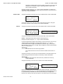
START-UP SEQUENCE
0000121d
START-UP SEQUENCE
After powering up or RESET
Honeywell
XL 50
V 2.04.00
>NEXT
Choose Applic.
>CONTR 16.08.00↑
1
↓
Please execute
Download
Date: 16.08.2000
Time: 14:29
Ctr. No:
4
>NEXT
>Default Points
Alarm History
CARE applications
(example, only)
Modem Part:
inactive
Appl. Mem. Size:
128 KB
>NEXT
><user addr.>
<user addr.>
<user addr.>
<user addr.>
>Contr. Setup
Select Applic.
Requ. Download
DP Wiring Check
><date>
↑
1
↓
<time>
<user addr.>
<val.>
<alarm text>
><user addr.>
<user addr.>
<user addr.>
<user addr.>
HW-Interf. Cfg.
>C-Bus
↑
Lon-Bus
1
B-Port
↓
<val.>↑
<val.>1
<val.>
<val.>↓
Embedded configurable
applications
Honeywell
XL 50
V 2.04.00
>NEXT
Honeywell
XL 50 V 2.04.00
AH01 V 1.00
>NEXT
Append Busnumber
to User Addr. ?
YES
>NEXT
Append Busnumber
to User Addr. ?
YES
>NEXT
1
C1<code> C2<code>
C3<code> C4<code>
C5<code> C6<code>
NEXT
<1st time pgm.> Init
MON 16.08. 10:27
TO: 20:30 20 °C
TODAY
>NEXT
3
4
B-Port Config.
Baudrate:> 9600
BACK
3
1
This screen is skipped in the HE01 application.
Instead, the bus number is appended automatically.
2
This screen appears only for certain applications
requiring eight configuration codes.
4
Additional options (“Meter Bus” and “Modem”,
respectively) viewable by scrolling downwards.
LON-Bus Config.
Ctr. Neuron ID:
000239026601
Bus ID:
>BACK
M-Bus Config.
Baudrate: <bdrate>
C-Bus Config.
Baudrate:> 38400
Ctr. No : 4
Bus ID:
BACK
>Config. Interf.
Enable Rem. B.
Please be
patient,
while firmware
restarts
BACK
Modem Config.
Baudrate: > 9600
GSM PIN ********
Reset Modm BACK
CONFIG
2
C7<code> C8<code>
Yes
Configuration
successful?
No
<1. time program>
MON 13.06. 10:27
TO: 20:30 20°C
TODAY
NEXT
After powering up the controller or after a RESET, the initial screen of the start-up
sequence appears. A RESET can be achieved by pressing the 'DOWN' and '–' keys
simultaneously.
NOTE: The screens of the start-up sequence are part of the operating system and
therefore always displayed in English.
49
EN2B-0137GE51 R0902
START-UP SEQUENCE
EXCEL 50 USER GUIDE
Honeywell
XL 50
V 2.04.00
>NEXT
This is the first screen of the start-up sequence. It shows the version of the
company name, the controller name, and the firmware version. The cursor is
positioned at 'NEXT' by default. Confirm with ENTER.
Date:>16.08.1998
Time:>14:29
Ctr. No:>4
>NEXT
Using the arrow keys, move the cursor to
— the 'Date' field to enter the current date.
— the 'Time' field to enter the current time.
— the ‘Ctr. No’ field to set the controller number.
If 'Date' is selected:
Set the date using the '+' or '–' keys. Use the arrow keys to move from field to field.
Confirm with ENTER. Using the arrow keys, move the cursor to 'BACK'. Confirm
with ENTER to return to the previous screen.
NOTE: The date must be entered in the following format: DD. MM. YYYY; for
example, 23. July 1997 must be entered as 23. 07. 1997. Press the
CANCEL key to abort the operation or to cancel an incorrect entry before
ENTER has been pressed. The value previously displayed will be
restored.
If 'Time' is selected:
Set the time using the '+' or '–' keys. Use the arrow keys to move from field to field.
Confirm with ENTER. Use the CANCEL key to return to the previous screen.
NOTE: The time must be entered in the following format: HH:MM in 24-hour clock
format; for example: 9:30 a.m. must be 09:30 and 9:30 p.m. must be
21:30. Press the CANCEL key to abort the operation or to cancel an
incorrect entry before ENTER has been pressed. The value previously
displayed will be restored.
If 'Ctr. No.' is selected:
Set the controller number using the '+' or '–' keys. Confirm with ENTER.
IMPORTANT
If no controller number is set or if the number shown is not reconfirmed,
the controller will not go online on the C-Bus after start-up.
Using the arrow keys, move the cursor to 'NEXT'. Confirm with ENTER.
Modem Part:
<active/inactive>
Appl. Mem. Size
128 KB
>NEXT
This screen provides information about whether modem communication is enabled
and about application memory size. Enabling modem communication and changing
the value for application memory are done in a later screen. The cursor is
positioned at 'NEXT' by default. Confirm with ENTER.
EN2B-0137GE51 R0902
50
EXCEL 50 USER GUIDE
START-UP SEQUENCE
>Contr. Setup
>Select Applic.
>Requ. Download
>DP Wiring Check
Using the arrow keys, move the cursor to
— 'Contr. Setup’ to configure the controller-specific hardware interfaces.
— 'Select Applic.' to choose the application manually.
— 'Requ. Download' to download an application from either the PC-based XI584
operator and service software or the XBS Central A.
— 'DP Wiring Check’ to set up the test mode with default user addresses.
Confirm with ENTER.
Controller Setup
If 'Contr. Setup.' has been selected, the following screen will appear:
HW-Interf. Cfg.
>B-Port
↑
C-Bus
1
LON-Bus
↓
The contents of this list box will depend upon the controller's exact hardware configuration. The listed interfaces to be configured will be from among the following:
•
•
•
•
•
B-Port
B-Port
C-Bus.
LON-Bus
Meter Bus
Modem
Using the arrow keys, move the cursor to ‘B-Port' and confirm with ENTER. The
following screen appears:
B-Port Config.
Baudrate: >9600
>BACK
Using the arrow keys, move the cursor to the value field. Use the '+' and '–' keys to
change the field. Confirm with ENTER.
NOTE: Live CARE is now capable of autodetecting the controller baud rate
setting, then of switching it temporarily to 38.4 Kbaud. When Live CARE is
disconnected, the controller will switch back to the previous baud rate
setting automatically within 15 seconds.
Using the arrow keys, move the cursor to 'BACK'. Confirm with ENTER.
C-Bus
Using the arrow keys, move the cursor to the ‘C-Bus' field and confirm with ENTER.
The following screen appears:
C-Bus Config.
Baudrate: >38400
Contr.No: ><no.>
>BACK
51
EN2B-0137GE51 R0902
START-UP SEQUENCE
EXCEL 50 USER GUIDE
NOTE: If you set the bus ID to a non-zero value, the C-bus baudrate will be
immediately disabled (i.e. it is then no longer editable). See also
section "LONW ORKS Bus" below.
Using the arrow keys, move to the appropriate value field.
If 'Baudrate' is selected:
Change the baud rate using the '+' and '–' keys. Confirm with ENTER.
If 'Contr. No.' is selected:
Change the controller number using the '+' or '–' keys. Confirm with ENTER.
IMPORTANT
If no controller number is set or if the number shown is not reconfirmed,
the controller will not go online on the C-Bus after start-up.
Using the arrow keys, move the cursor to 'BACK'. Confirm with ENTER.
LONWORKS Bus
Using the arrow keys, move the cursor to ‘LON-Bus' and confirm with ENTER. The
following screen appears:
LON-Bus Config.
Contr. Neuron ID
<neuron ID number>
Bus ID
>BACK
This screen displays the unique identification number for the Neuron processor in
the controller.
Using the arrow keys, move the cursor to 'BACK'. Confirm with ENTER.
IMPORTANT
The bus ID is a non-unique number (i.e. different Excel 500 controllers can
have the same bus ID in common) between 0 and 99 (inclusive) which the
user can edit after a reset during the controller's start-up sequence or by
changing the configuration property nciXL500BusSetup. The factory
default is "0".
Meter Bus
Using the arrow keys, move the cursor to the ‘M-Bus' field and confirm with ENTER.
The following screen appears:
M-Bus Config.
Baudrate: >9600
>BACK
Using the arrow keys, move the cursor to the value field. Use the '+' and '–' keys to
change the field. Confirm with ENTER.
Using the arrow keys, move the cursor to 'BACK'. Confirm with ENTER.
Modem Communication
Using the arrow keys, move the cursor to ‘Modem’ and confirm with ENTER. If
modem communication has not yet been enabled, the following screen appears:
Config. Interf.
Enable Rem. B.
This screen allows the user to enable modem communication. If you select 'Enable
Rem. B.', you will be asked to wait while the firmware is restarted. If modem
communication is already enabled, the following screen will appear:
EN2B-0137GE51 R0902
52
EXCEL 50 USER GUIDE
START-UP SEQUENCE
Config. Interf.
Config. Rem. B.
Disable Rem. B.
If 'Config. Interf.' Is selected, the following screen appears:
Modem Config.
Baudrate: 9600
GSM PIN ********
Reset Modm >NEXT
Using the arrow keys, move the cursor to
— ‘Baudrate’ to set the baud rate for the modem/ISDN terminal adapter.
— ‘GSM PIN’ to set the GSM Personal Identification Number (PIN).
— 'Reset Modem' to return modem to factory settings, erasing any custom
modem initialization. See section "Remote Communications" of the Excel 50
Controller Installation Instructions, EN1B-101, for more information.
Using the arrow keys, move the cursor to the appropriate value fields. Use the '+'
and '–' keys to change the fields.
NOTE: The GSM PIN must be entered right-justified.
NOTE: For GSM communication, the modem baud rate must be set at 9600.
Or select 'Config. Rem. B.' to go to the next screen:
Appl. Mem. Size
128 KB RESTART
Rem. Trend Buf.:
104 Entr. >BACK
This screen is used to increase the size of the adjustable remote trend buffer by
reducing the application memory size. The number of entries (trend samples) that
can be stored in the buffer for Remote Building Central A is determined by a calculation by the controller based upon the Application Memory Size entered in this
screen and the size of the RAM module. See "Adjustable Remote Trend Buffer
(V2.03.x)" for details of the calculation.
If a new value for Appl. Mem. Size has not been entered, the cursor is positioned at
'BACK' by default. Confirm with ENTER and return to the previous screen.
To increase the size of the buffer, use the arrow keys to select the digits for ‘Appl.
Mem. Size’ and use the ‘+’ and '–' keys to enter a new value. Then use the arrow
keys to move the cursor to 'RESTART' and confirm with ENTER. The controller will
reset again, and the start-up sequence starts again from the beginning.
IMPORTANT
If the application being downloaded exceeds the Maximum Application
Size entered in this screen, an error message will occur and the download
will not be executed (see NOTE).
When this screen appears again, the cursor is positioned at 'BACK' by default. The
new application memory size and the new number of trend samples calculated by
the controller are shown. Confirm with ENTER and return to the previous screen.
53
EN2B-0137GE51 R0902
START-UP SEQUENCE
EXCEL 50 USER GUIDE
Select Application
>Contr. Setup
>Select Applic.
>Requ. Download
>DP Wiring Check
If 'Select Applic.' has been selected from the screen shown above, the following
screen will appear listing applications and their burn dates:
Select Applic.
>AH01
↑
<applic.> <date.> 1
<applic.> <date.> ↓
Using the arrow keys, move the cursor to the desired application. Confirm with
ENTER.
Honeywell
XL 50 V 2.03.00
AH01
V 1.00
>NEXT
This line appears in
configurable applications only.
The initialization screen of the chosen application will appear. It displays information
about the versions of the controller and the application. Confirm with ENTER.
If the Excel 50 controller is connected to a C-Bus, this screen will appear:
Append Busnumber
to User Addr. ?
>YES
>NEXT
Using the arrow keys, move the cursor to the 'YES' field. Confirm with ENTER.
IMPORTANT
If more than one Excel 50 Controller with the same application program is
connected to the C-Bus, the user addresses must have the bus numbers
appended to them.
Using the arrow keys, move the cursor to 'NEXT'. Confirm with ENTER.
>CONFIG
C2>-1
C4>-1
C6>-1
C1>-1
C3>-1
C5>-1
This screen appears in
configurable applications only.
In this screen, the codes of the configurable application can be changed. The
application codes can be generated with the 'LIZARD-Excel 50 Application
Selector'. This screen does not appear with standard and custom CARE
applications.
NOTE: Not all applications have six configuration code numbers. Applications
with eight configuration codes have two on a second screen as shown
below.
First screen:
EN2B-0137GE51 R0902
54
EXCEL 50 USER GUIDE
START-UP SEQUENCE
C1>-1
C3>-1
C5>-1
C2>-1
C4>-1
C6>-1
>NEXT
Second screen:
>CONFIG
C7>-1
C8>-1
NOTE: If the 'LIZARD-Excel 50 Application Selector' is not available, please
contact your local Honeywell branch for support.
Using the arrow keys, move the cursor to the appropriate code and change its value
using the '+' and '–' keys.
Using the arrow keys, move the cursor to the 'CONFIG' field. Confirm with ENTER.
If the codes entered in the screen are allowed, the default screen of normal
operation will appear:
<1. time program>Init
MON 13.06. 10:27
TO: 20:30 20°C
>TODAY
>NEXT
If one or more codes entered are not allowed, the initialization screen will appear
again. Change the screens by using the arrow keys to move the cursor to 'NEXT'
and confirming with ENTER until you have returned to the configuration screen.
Codes which are not allowed have the value '-1' instead of the previously entered
code. Change the codes until all codes are correct.
You will now come to the default screen of normal operation:
<1. time program>Init
MON 13.06. 10:27
TO: 20:30 20°C
>TODAY
>NEXT
Refer to the chapter 'Plant key' for information about this screen.
Request Download
>Contr. Setup
>Select Applic.
>Requ. Download
>DP Wiring Check
If 'Requ. Download’ has been selected from the screen shown above, the following
screen appears.
55
EN2B-0137GE51 R0902
START-UP SEQUENCE
EXCEL 50 USER GUIDE
Please execute
Download
Follow the instructions for a download given in the XI584 User Guide or Lizard User
Guide (if downloading via B-Port) or the User Guide for the Building Central (if by CBus).
NOTE: After download of an application, the controller checks the CARE
application's User ID via its checksum and will not start the application if it
is invalid. An alarm 'Invalid User ID' will be issued.
Data Point Wiring Check
>Contr. Setup
>Select Applic.
>Requ. Download
>DP Wiring Check
If 'DP Wiring Check’ has been selected from the screen shown above, default user
addresses are generated following the following pattern:
AI0101
AO0201
DI0301
DO0401
— Analog input, board 1, input 1
— Analog output, board 2, output 1
— Digital input, board 3, input 1
— Digital output, board 4, output 1
NOTE: The board numbers shown above are internal references and are not
relevant to the User. In Excel 50 Controllers, the numbers are fixed for the
I/O type, i.e. analog inputs are always AI01, digital inputs are always DI03,
etc.
After generating the default addresses, the following screen appears:
>Default Points
>Alarm History
Using the arrow keys, move the cursor to
— 'Default Points to display I/O points for checking values and manually setting
outputs for testing.
— 'Alarm History' to display current alarms. This feature allows the system to be
checked out by a single person opening and closing inputs and then later
reading the alarm buffer to see if they were detected by the controller.
Confirm with ENTER.
If ‘Default Points’ has been selected, the following screen will be displayed showing
all default user addresses and their current values.
><user addr.>
><user addr.>
><user addr.>
><user addr.>
<val>↑
<val>1
<val>
<val>↓
To manually set outputs, use the arrow keys to move the cursor to the appropriate
output point from the list box. Confirm with ENTER.
For analog points the following screen is displayed.
EN2B-0137GE51 R0902
56
EXCEL 50 USER GUIDE
START-UP SEQUENCE
<user addr.>
STATE/VALUE:
> 0.00%
Confirm the displayed value with ENTER, or change the value using the '+' or '–'
keys. Confirm with ENTER. In the case of digital points, the following screen is
displayed.
<user addr.>
STATE/VALUE:
>0
%
Confirm the displayed value with ENTER, or change the value/state using the '+' or
'–' keys. Confirm with ENTER.
Press CANCEL to return to the previous screen (list of user addresses).
If ‘Alarm History’ has been selected, the following screen will be displayed showing
all points in alarm as well as any system alarms (max. 100 entries):
><user addr.>
><user addr.>
><user addr.>
><user addr.>
↑
1
↓
NOTE: Alarms are generated for changes of state/value on inputs, which allows
shorting and opening the inputs at the switches and/or sensors and then
checking the alarm buffer to verify the wiring.
To view an alarm, use the arrow keys to move the cursor to the default user
address from the list box. Confirm with ENTER. The following screen will appear:
<date.>
<user addr.>
<value>
<alarm text>
<time>
Press CANCEL to return to the previous screen.
IMPORTANT
Reset the controller after using the test options to clear the alarm buffer.
Adjustable Remote Trend Buffer (V2.03.x)
With firmware 2.03.00 or newer, memory that is not used by the application can be
used as additional remote trend buffer for XBS Central A. By maximizing the trend
buffer size, the number of times the controller must dial-up the central is minimized
as is the risk of trend samples being overwritten due to a full buffer.
By exploiting this feature, it is possible to use the EXCEL controller as a pure
trending device, when no application is downloaded.
The amount of additional memory available for the remote trend buffer is determined by the value for 'Application Memory Size' entered with the MMI during the
57
EN2B-0137GE51 R0902
START-UP SEQUENCE
EXCEL 50 USER GUIDE
controller's start-up sequence. This number is subtracted from the total application
memory, and the resulting number, in Kbytes, is the additional remote trend buffer
size. The following figure illustrates the adjustable remote trend buffer.
TOTAL APPLICATION MEMORY
REMOTE TREND BUFFER
UNUSED APPLICATION MEMORY
e.g. 58 KBYTES
58 KBYTES
= 1263 ADDITIONAL TREND SAMPLES
APPLICATION
e.g. 70 KBYTES
128
KBYTES
+ 104 TREND SAMPLES (DEFAULT)
= 1367 T0TAL TREND SAMPLES
Figure 1. Adjustable remote trend buffer example.
The maximum number of trend samples will be displayed on the MMI once a value
for application memory size is entered.
The adjustment range for the application memory size is the following:
Application memory size
Default:
128 Kbyte
Trend samples in remote trend buffer
104 per central
Maximum: 128 Kbyte
104 per central
Minimum:
104 per central, PLUS “N” for central A
38 Kbyte
For the XD52-FC application module:
N = (128 Kbytes - appl. size(in Kbytes) + 384 Kbytes) * 1024 bytes / 47 bytes
For all other application modules equipped with Flash EPROMS:
N = (128 Kbytes - appl. size (in Kbytes)) * 1024 bytes / 47 bytes
Hence, the maximum value of N is 10,327 trend samples for the XD52-FC application module and 1,960 trend samples for all others containing Flash memory.
This means that for all Flash memory-equipped modules with a minimum
application size of 38 Kbytes, there will be 2,064 (1,960 + 104) trend samples for
central A and 104 trend samples for central B and C each.
If an application being downloaded exceeds the application memory size, a warning
message will be displayed on the MMI, and the download will not be executed.
EN2B-0137GE51 R0902
58
EXCEL 50 USER GUIDE
OPERATOR ACCESS LEVELS
Password protection ensures that only authorized personnel have access to system
data to ensure reliable and trouble-free operation using the preset values.
The Operator access level 1 is not password-protected. This level enables only to
read such data as setpoints, switching time points, and operating hours.
The Operator access levels 2 and 3 are password-protected. Authorized personnel
can change the preset values at those levels. Operator access levels 2 and 3 have
different passwords.
Operator access level 1 - read only (default values)
- no password
Operator access level 2 - read and limited changes
- level-2 password
Operator access level 3 - read and make unlimited changes - level-3 password
TIME PROGRAM DESCRIPTION
Direct access to the time program menu can be obtained via the fast-access key.
Pressing the 'Time program' fast-access key displays the password entry screen.
Refer to section "Modifying a Password" for help with password entry.
Time programs are used to assign setpoint values and control status conditions to
specific user addresses at specific times.
The time program can be adapted to suit the application. A time program comprises
the system time (which includes the current date, time and daylight savings time)
and various time-related programs, the daily time programs, the weekly time
program (created from daily time programs) and the annual time program. Time
program switching points can be changed via operator access levels 2 and 3.
System Time
Daily Time Program
The system time includes the current date and time and the start and end date of
the daylight savings time. It regulates all analog and digital control strategies
implemented in the application software program.
Switching point times with the desired value/status for the appropriate user
addresses are entered into the daily time program.
Example: The daily time program 'Workday' has several switching point times:
Workday
Weekly Time Program
06:00
AH1_occ
08:00
AH1_tsp
09:00
AH1_psp
Daily time programs are assigned to each day of the week in the weekly time
program. The weekly time program is automatically repeated every week and
creates the normal annual time program.
Example 1: Monday to Friday inclusive require the same daily time program.
Saturday and Sunday require a different daily time program:
Monday
Workday
Tuesday
Workday
Wednesday
Workday
Thursday
Workday
Friday
Workday
Saturday
Weekend
Sunday
Weekend
59
EN2B-0137GE51 R0902
TIME PROGRAM DESCRIPTION
EXCEL 50 USER GUIDE
Example 2: Thursday requires a different daily program and is assigned to the daily
time program DP_2:
Monday
Workday
Tuesday
Workday
Wednesday
Workday
Thursday
DP_2
Friday
Workday
Saturday
Weekend
Sunday
Weekend
NOTE: If the 'COPY' function is used to create a new daily time program the next
free daily time program will be assigned. This means that the default daily
time program can be overridden by a new daily time program. Daily time
programs cannot be deleted from the PC central.
Annual Time Program
The annual time program can be changed for a specific period. A daily time
program out of the daily time program list can be assigned to a period which is
specified by the beginning and end date.
Example: The annual program consists of the normal weekly program. Only during
the holiday period every day is assigned to the 'Weekend' daily time program.
Optimization
From 01.01.1997 to 15.07.1997
normal weekly program
From 15.07.1997 to 30.08.1997
'Weekend' daily time program
From 30.08.1997 to 31.12.1997
normal weekly program
The optimization function causes optimization of a switching point. It has two states,
ON and OFF.
The optimization compensates the time an environment needs to reach a wanted
condition (temperature, humidity, etc.) by bringing forward the switching point of the
corresponding device.
NOTE: The optimization can only be set to ON if the user address of the device is
suitable for optimization.
Example: If the optimization is ON, a heating plant is switched on early in order to
have your home at the required setpoint level by a particular time.
Programmed switching point:
6:00 to 20 °C
Real switching point:
4:52 to heating ON
The difference between the programmed and real switching point is the estimated
time a room needs to warm up under the current conditions.
EN2B-0137GE51 R0902
60
EXCEL 50 USER GUIDE
DATA POINTS / PARAMETERS DESCRIPTION
Direct access to the 'Data points / parameters' menu can be obtained via the fastaccess key. Pressing the 'Data points / parameters' fast-access key displays the
password entry screen. Refer to the section entitled 'Password procedure' for help
with password entry. Access to change value/status depends on the operator
access level.
The attribute "User Address"
The Excel 50 controller has physical, remote, and pseudo data points. The user
address is an attribute of the data point. Each user address represents one data
point.
Information can be obtained about the following data point types:
Physical data points
analog inputs
analog outputs
digital inputs
digital outputs
totalizers
Physical data points are inputs and outputs directly connected to a hardware device
such as a sensor or an actuator. The Excel 50 controller is equipped for 22 physical
data points.
Pseudo data points
pseudo analog
pseudo digital
pseudo totalizers
Pseudo data points are generated in software to achieve the application program.
They are not connected to any hardware device. The Excel 50 can handle a
maximum of 128 pseudo points of each type.
Remote points
remote analog
remote digital
Remote points (also known as global points) are data points which are used by
more than one controller on the same bus. The controller number for the device that
is the source of remote point must be entered (via MMI) in the controller receiving
the point.
The data points / parameters fast-access key also provides access to the following
data
parameters
system data
DDC program cycle time
M-Bus configuration
NV mapping (V2.04.00)
Beginning with V2.04.00 firmware implemented with an XD-52FC controller, there
may be physical points mapped to LONW ORKS network variables (NVs) and not
assigned to any I/O board. In this case, the technical address number will be 0.
Mapped NVs can be displayed like point attributes, including the nvi or nvo name
and NV index (range: 0 t0 4095, with 0xFFFF indicating the data point is not
mapped.
61
EN2B-0137GE51 R0902
DATA POINTS / PARAMETERS DESCRIPTION
EXCEL 50 USER GUIDE
Data Point Attributes
The following data points are available on the operator's terminal.
Different attributes are assigned to each data point type as follows:
Analog Inputs
User Address
Descriptor
Technical Address
Operating Mode
Value
Manual Value
Engineering Unit
Suppress Alarm
Min Limit 2
Min Limit 1
Max Limit 1
Max Limit 2
Sensor Offset
Trend Log
Trend Hysteresis
Trend Cycle
Nv(i/o) Index
Nv(i/o) Name
Digital Outputs
User Address
Descriptor
Technical Address
Operating Mode
Value
Manual Value
Alarm Reporting
Hours Run
Suppress Alarm
Trend Log
Normally Open/Normally Closed
Nv(i/o) Index
Nv(i/o) Name
Pseudo Digital Points
User Address
Descriptor
Operating Mode
Value
Manual Value
Suppress Alarm
Hours Run
Trend Log
Nv(i/o) Index
Nv(i/o) Name
Analog Outputs
User Address
Descriptor
Technical Address
Operating Mode
Value
Manual Value
Engineering Unit
Suppress Alarm
Time to Open/Time to Close
Trend Log
Trend Hysteresis
Trend Cycle
Nv(i/o) Index
Nv(i/o) Name
Totalizer Inputs
User Address
Descriptor
Technical Address
Operating Mode
Value
Manual Value
Suppress Alarm
Trend Log
Pseudo Totalizer Inputs
User Address
Descriptor
Operating Mode
Value
Manual Value
Suppress Alarm
Trend Log
Digital Inputs
User Address
Descriptor
Technical Address
Operating Mode
Value
Manual Value
Alarm Reporting
Hours Run
Suppress Alarm
Trend Log
Normally Open/Normally Closed
Nv(i/o) Index
Nv(i/o) Name
Pseudo Analog Points
User Address
Descriptor
Operating Mode
Value
Manual Value
Engineering Unit
Suppress Alarm
Min Limit 2
Min Limit 1
Max Limit 1
Max Limit 2
Trend Log
Trend Hysteresis
Trend Cycle
Nv(i/o) Index
Nv(i/o) Name
Remote Data Points
User Address
Technical Address
Value
Engineering Unit
Trend Log
EN2B-0137GE51 R0902
62
EXCEL 50 USER GUIDE
DATA POINTS / PARAMETERS DESCRIPTION
Operating Mode
This attribute enables the user to switch between manual and automatic operation.
Automatic operation
Manual operation
Under normal automatic operation, the controller processes the values at the
inputs, e.g. from temperature sensors. For outputs, under normal operation, the
status shown by the user / time program is adopted, e.g. 'Heating circuit pump off'.
The feedback loop of the control system is closed.
During manual operation, the controller uses the manual values, e. g. 'Flow temperature setpoint = 60 °C'. Outputs adopt the preselected condition, e. g. 'Heating
circuit pump on'. The feedback loop of the control system is interrupted.
For automatic operation, the attribute "Operating Mode" contains the inputs 'Auto'
and 'Manual'. Each change from automatic to manual and back again generates a
critical alarm.
Value
Manual value
When the controller is working in automatic mode (the attribute "Operating Mode" is
set to 'Auto'), the value or the current status being processed by the application
program can be found in the attribute "Value". The attribute "Value" for an analog
input is, for example, the current room temperature of 21 °C / 70 °F. The attribute
"Value" for a pump switched by the digital output is, for example, the current status
'ON'.
When the controller is working in manual mode (the attribute "Operating Mode" is
set to 'Manual'), the preset manual values can be found in the attribute "Manual
Value".
Example:
In the example shown, the attribute "Operating Mode" is set to 'Manual',
i.e. the data specified manually is written into the attribute "Manual Value",
processed in the controller, and passed on to an output. The user can, of
course, recall the measured value coming from the attribute "Value", but
this has no effect on the application program.
Hours Run
An hours run log can be carried out for digital data points (physical and pseudo),
e.g. Iogging the hours run by a heating circuit pump. The accumulated hours run
are displayed in the attribute "Hours Run". The corresponding values have a
resolution of 1 minute.
63
EN2B-0137GE51 R0902
DATA POINTS / PARAMETERS DESCRIPTION
EXCEL 50 USER GUIDE
Technical Address
The Excel 50 controller has 22 physical inputs / outputs. Each physical data point
has a fixed technical address containing information about the controller number,
the board number, and the input / output number on the board.
User Address
The 14-character user address for each data point (physical and pseudo) can be
displayed on the operator's terminal. Access to change all physical and pseudo
data points depends on the operator's access level.
NOTE: In the case of configurable applications, only, if more than one controller
with the same application program exists on the C-bus, the controller
number must be attached to the user address and the controller name to
make the user addresses unique.
The user addresses can be changed during the start-up or cold start via the
operator's terminal by confirming with 'YES' in the 'Append bus number to user
address?' screen. Refer to the diagram below.
If the 'YES' field is selected, the controller number will be automatically attached to
the controller name (characters 14 and 15) and to the user address (characters 17
and 18).
Example
The user address is 'RoomTemp'.
Controller number: 02
If the user address is changed, the following text string will be displayed:
RoomTemp------02
The controller number is displayed only on the PC central and not on the operator's
terminal.
Suppress Alarm
The attribute "Suppress Alarm" allows the user to choose which point alarm will be
generated and which one not.
In case "Suppress Alarm" is set to YES, there will be no alarm generated, even if
the alarm condition of this data point occurs.
ALARM DESCRIPTION
Direct access to the alarm handling menu can be obtained via the 'Alarms' fastaccess key. The alarm handling facility within the controller stores alarm data for
immediate display at the operator's terminal.
Pressing the 'Alarms' fast-access key displays the main alarm menu screen to
enable selection of the following:
•
•
•
•
Typical alarm information
EN2B-0137GE51 R0902
alarm buffer
points in alarm
critical alarms
non-critical alarms.
- Date and time the alarm occurred
- User address of the point in alarm
- Value/status of the point in alarm
- Alarm text, e.g. MIN1 alarm.
64
EXCEL 50 USER GUIDE
Alarm buffer
The last 99 alarms are stored in the alarm buffer. They contain the user address,
alarm text, date and time. When the alarm memory capacity is exceeded, the first
alarm is overwritten. Alarms are organized on a first in, first out basis. The contents
of the alarm buffer can be displayed on the operator's terminal.
Point in alarm
All data points currently in an alarm condition, i.e. the alarm limit for an analog point
or the alarm status for a digital point has been reached, can be displayed on the
operator's terminal. When selecting this option, the user address and associated
alarm text will be displayed.
Critical and non-critical alarms
Alarm attributes
The following attributes can generate alarms and will write them into the alarm
buffer as well as sending them to the PC central via the C-Bus.
"Operating Mode"
"Min Limit"
"Max Limit"
always a critical alarm
optional critical or alarm status
optional critical or totalizer alarm status
While the attribute "Operating mode" always results in a critical alarm, the attribute
"Alarm Type" offers a choice of critical or non-critical alarm classification for the
attributes "Min Limit", "Max Limit", "Totalizer", and "Alarm Status".
System alarms description
Operating malfunctions that arise within a controller, e.g. power failure or during
communication with another Excel 5000 device, are displayed on the operator's
terminal.
System alarms are always critical alarms.
Min. / max. limit monitoring
Two maximum limits ('Max Lim1' and 'Max Lim2') and two minimum limits
('Min Lim1' and 'Min Lim2') can be independently set for physical and pseudo
analog inputs.
The limit values can be changed using the operator sequence. Each time a limit
value is reached, irrespective of direction, an alarm is generated.
The following four limit values are available:
minimum limit 2
minimum limit 1
maximum limit 1
maximum limit 2
65
EN2B-0137GE51 R0902
ALARM DESCRIPTION
EN2B-0137GE51 R0902
EXCEL 50 USER GUIDE
66
EXCEL 50 USER GUIDE
67
EN2B-0137GE51 R0902
EXCEL 50 USER GUIDE
By using this Honeywell literature, you agree that Honeywell will have no liability for any damages arising out of your
use or modification to, the literature. You will defend and indemnify Honeywell, its affiliates and subsidiaries, from and
against any liability, cost, or damages, including attorneys’ fees, arising out of, or resulting from, any modification to the
literature by you.
Control Products
Honeywell Inc.
Honeywell Plaza
P.O. Box 524
Minneapolis, MN 55408-0524
USA
http://www.honeywell.com
Control Products
Honeywell Limited-Honeywell Limitee
155 Gordon Baker Road
North York, Ontario
M2H 3N7
Canada
http://www.honeywell.ca
EN2B-0137GE51 R0902 /74-3030-3
Control Products
Honeywell AG
Böblinger Straβe 17
D-71101 Schönaich
Germany
http://europe.hbc.honeywell.com
printed in Germany
Subject to change without notice