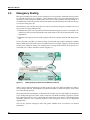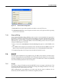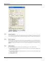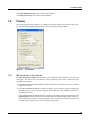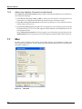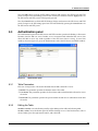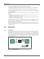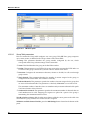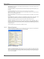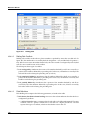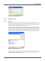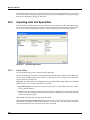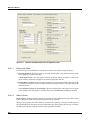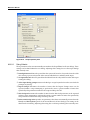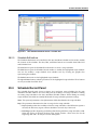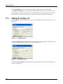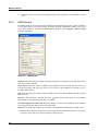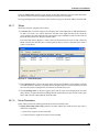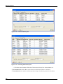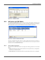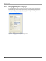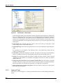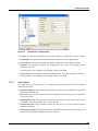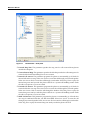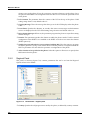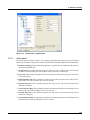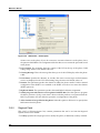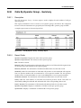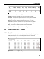
1
Media
Exchange
Administrator’s
Manual
Manual Part Number 90-18001
Zultys Technologies
771 Vaqueros Avenue
Sunnyvale CA 94085-5327
USA
+1-408-328-0450
http://www.zultys.com
Notice
The information contained in this document is subject to change without notice.
Zultys Technologies makes no warranty of any kind with regard to this material, including, but
not limited to, the implied warranties of merchantability and fitness for a particular purpose.
Zultys Technologies shall not be liable for errors contained herein or for incidental or consequential
damages in connection with the furnishing, performance, or use of this material.
Zultys Technologies assumes no responsibility for the use or reliability of interconnected
equipment that is not furnished by Zultys Technologies.
This document contains proprietary information which is protected by copyright. The contents of
this manual and the associated software are the property of Zultys Technologies, and all rights are
reserved. No part of this document may be photocopied, reproduced, stored in any computer
format, translated to another language, or publicly displayed without the prior written consent of
Zultys Technologies.
The information contained herein has been prepared by Zultys Technologies solely for use by
Zultys’s employees, agents, and customers. Dissemination or use of the information or concepts
contained herein to or by other parties is prohibited without prior written consent from Zultys
Technologies.
Zultys, the Zultys logo, the Zultys mark, and Zultys product names are trademarks of Zultys
Technologies and may be registered trademarks in certain countries. All other names may be
trademarks or registered trademarks of their respective owners.
Revision History
Release
Release Date
0.1.1
06 May 2003
1.0.1
14 July 2003
1.2.I
21 January 2004
2.0.3
07 July 2004
2.0.4
14 September 2004
2.2.1
09 November 2004
2.2.4
04 February 2005
2.4.0
28 April 2005
2.6.0
01 June 2005
2.6.4
30 August 2005
3.0.0
07 July 2006
Contents
Chapter 1
Introduction . . . . . . . . . . . . . . . . . . . . . . . . . . . . . . . . . . . . . . . . . . . . . . . . .
1.1
Scope. . . . . . . . . . . . . . . . . . . . . . . . . . . . . . . . . . . . . . . . . . . . . . . . . . . . . . . . .
1.2
Getting Started . . . . . . . . . . . . . . . . . . . . . . . . . . . . . . . . . . . . . . . . . . . . . . . .
1.3
Documentation Overview. . . . . . . . . . . . . . . . . . . . . . . . . . . . . . . . . . . . . . .
1.4
Forms of Documentation. . . . . . . . . . . . . . . . . . . . . . . . . . . . . . . . . . . . . . . .
1.5
Colophon . . . . . . . . . . . . . . . . . . . . . . . . . . . . . . . . . . . . . . . . . . . . . . . . . . . . .
1.6
Documentation Feedback . . . . . . . . . . . . . . . . . . . . . . . . . . . . . . . . . . . . . . .
Chapter 2
User Interface Basics. . . . . . . . . . . . . . . . . . . . . . . . . . . . . . . . . . . . . . . . . . 7
2.1
Introduction. . . . . . . . . . . . . . . . . . . . . . . . . . . . . . . . . . . . . . . . . . . . . . . . . . . 7
2.2
PC Requirements . . . . . . . . . . . . . . . . . . . . . . . . . . . . . . . . . . . . . . . . . . . . . . 7
2.3
Installing the User Interface . . . . . . . . . . . . . . . . . . . . . . . . . . . . . . . . . . . . . 8
2.4
Starting the User Interface Software . . . . . . . . . . . . . . . . . . . . . . . . . . . . . . 9
2.5
Login Accounts . . . . . . . . . . . . . . . . . . . . . . . . . . . . . . . . . . . . . . . . . . . . . . . . 9
2.6
Software Versions . . . . . . . . . . . . . . . . . . . . . . . . . . . . . . . . . . . . . . . . . . . . . 11
2.7
Menu Structure . . . . . . . . . . . . . . . . . . . . . . . . . . . . . . . . . . . . . . . . . . . . . . . 13
2.8
Enabling User Interface Changes. . . . . . . . . . . . . . . . . . . . . . . . . . . . . . . . 20
2.9
Provisioning the MX for the First Time. . . . . . . . . . . . . . . . . . . . . . . . . . . 21
2.10
Shutting Down the MX . . . . . . . . . . . . . . . . . . . . . . . . . . . . . . . . . . . . . . . . 22
Chapter 3
Locations . . . . . . . . . . . . . . . . . . . . . . . . . . . . . . . . . . . . . . . . . . . . . . . . . .
3.1
Introduction. . . . . . . . . . . . . . . . . . . . . . . . . . . . . . . . . . . . . . . . . . . . . . . . . .
3.2
Importance of Locations . . . . . . . . . . . . . . . . . . . . . . . . . . . . . . . . . . . . . . .
3.3
Emergency Routing . . . . . . . . . . . . . . . . . . . . . . . . . . . . . . . . . . . . . . . . . . .
3.4
Configuring Locations on the MX . . . . . . . . . . . . . . . . . . . . . . . . . . . . . . .
23
23
23
24
25
Chapter 4
System Clock . . . . . . . . . . . . . . . . . . . . . . . . . . . . . . . . . . . . . . . . . . . . . . .
4.1
Introduction. . . . . . . . . . . . . . . . . . . . . . . . . . . . . . . . . . . . . . . . . . . . . . . . . .
4.2
Using NTP Server . . . . . . . . . . . . . . . . . . . . . . . . . . . . . . . . . . . . . . . . . . . . .
4.3
Setting the Time Manually . . . . . . . . . . . . . . . . . . . . . . . . . . . . . . . . . . . . .
4.4
System Clock window . . . . . . . . . . . . . . . . . . . . . . . . . . . . . . . . . . . . . . . . .
29
29
29
30
30
Chapter 5
SIP and RTP Settings. . . . . . . . . . . . . . . . . . . . . . . . . . . . . . . . . . . . . . . . .
5.1
Introduction. . . . . . . . . . . . . . . . . . . . . . . . . . . . . . . . . . . . . . . . . . . . . . . . . .
5.2
SIP Settings . . . . . . . . . . . . . . . . . . . . . . . . . . . . . . . . . . . . . . . . . . . . . . . . . .
5.3
SIP Timers panel . . . . . . . . . . . . . . . . . . . . . . . . . . . . . . . . . . . . . . . . . . . . . .
5.4
RTP Settings. . . . . . . . . . . . . . . . . . . . . . . . . . . . . . . . . . . . . . . . . . . . . . . . . .
33
33
33
34
36
Chapter 6
Codecs . . . . . . . . . . . . . . . . . . . . . . . . . . . . . . . . . . . . . . . . . . . . . . . . . . . . 39
6.1
Introduction. . . . . . . . . . . . . . . . . . . . . . . . . . . . . . . . . . . . . . . . . . . . . . . . . . 39
1
1
2
3
4
5
5
i
Contents
6.2
6.3
6.4
ii
MX Codecs . . . . . . . . . . . . . . . . . . . . . . . . . . . . . . . . . . . . . . . . . . . . . . . . . . . 39
MX Codec Usage. . . . . . . . . . . . . . . . . . . . . . . . . . . . . . . . . . . . . . . . . . . . . . 40
Codec Profiles window . . . . . . . . . . . . . . . . . . . . . . . . . . . . . . . . . . . . . . . . 41
Chapter 7
System Settings . . . . . . . . . . . . . . . . . . . . . . . . . . . . . . . . . . . . . . . . . . . . .
7.1
Purpose. . . . . . . . . . . . . . . . . . . . . . . . . . . . . . . . . . . . . . . . . . . . . . . . . . . . . .
7.2
Company . . . . . . . . . . . . . . . . . . . . . . . . . . . . . . . . . . . . . . . . . . . . . . . . . . . .
7.3
IP Addresses . . . . . . . . . . . . . . . . . . . . . . . . . . . . . . . . . . . . . . . . . . . . . . . . .
7.4
Servers . . . . . . . . . . . . . . . . . . . . . . . . . . . . . . . . . . . . . . . . . . . . . . . . . . . . . .
7.5
DHCP . . . . . . . . . . . . . . . . . . . . . . . . . . . . . . . . . . . . . . . . . . . . . . . . . . . . . . .
7.6
Proxies. . . . . . . . . . . . . . . . . . . . . . . . . . . . . . . . . . . . . . . . . . . . . . . . . . . . . . .
7.7
Misc . . . . . . . . . . . . . . . . . . . . . . . . . . . . . . . . . . . . . . . . . . . . . . . . . . . . . . . . .
45
45
45
47
48
51
53
54
Chapter 8
Bandwidth Management . . . . . . . . . . . . . . . . . . . . . . . . . . . . . . . . . . . . . .
8.1
Introduction. . . . . . . . . . . . . . . . . . . . . . . . . . . . . . . . . . . . . . . . . . . . . . . . . .
8.2
Bandwidth Limits . . . . . . . . . . . . . . . . . . . . . . . . . . . . . . . . . . . . . . . . . . . . .
8.3
Configuring Bandwidth Limits . . . . . . . . . . . . . . . . . . . . . . . . . . . . . . . . .
57
57
57
58
Chapter 9
SIP Servers and ITSPs . . . . . . . . . . . . . . . . . . . . . . . . . . . . . . . . . . . . . . . .
9.1
Introduction. . . . . . . . . . . . . . . . . . . . . . . . . . . . . . . . . . . . . . . . . . . . . . . . . .
9.2
SIP Servers panel and ITSPs panel . . . . . . . . . . . . . . . . . . . . . . . . . . . . . .
9.3
Authentication panel . . . . . . . . . . . . . . . . . . . . . . . . . . . . . . . . . . . . . . . . . .
61
61
61
65
Chapter 10
Analog Configuration . . . . . . . . . . . . . . . . . . . . . . . . . . . . . . . . . . . . . . . . .
10.1
Introduction. . . . . . . . . . . . . . . . . . . . . . . . . . . . . . . . . . . . . . . . . . . . . . . . . .
10.2
FXS Circuits . . . . . . . . . . . . . . . . . . . . . . . . . . . . . . . . . . . . . . . . . . . . . . . . . .
10.3
FXO Circuits . . . . . . . . . . . . . . . . . . . . . . . . . . . . . . . . . . . . . . . . . . . . . . . . .
10.4
System Failure Transfer . . . . . . . . . . . . . . . . . . . . . . . . . . . . . . . . . . . . . . . .
67
67
67
70
75
Chapter 11
PCM Configuration. . . . . . . . . . . . . . . . . . . . . . . . . . . . . . . . . . . . . . . . . . .
11.1
Introduction. . . . . . . . . . . . . . . . . . . . . . . . . . . . . . . . . . . . . . . . . . . . . . . . . .
11.2
Clock Sources . . . . . . . . . . . . . . . . . . . . . . . . . . . . . . . . . . . . . . . . . . . . . . . .
11.3
Usage panel . . . . . . . . . . . . . . . . . . . . . . . . . . . . . . . . . . . . . . . . . . . . . . . . . .
11.4
Voice panel . . . . . . . . . . . . . . . . . . . . . . . . . . . . . . . . . . . . . . . . . . . . . . . . . .
11.5
Map Panel . . . . . . . . . . . . . . . . . . . . . . . . . . . . . . . . . . . . . . . . . . . . . . . . . . .
77
77
77
78
79
84
Chapter 12
BRI Configuration. . . . . . . . . . . . . . . . . . . . . . . . . . . . . . . . . . . . . . . . . . . .
12.1
Introduction. . . . . . . . . . . . . . . . . . . . . . . . . . . . . . . . . . . . . . . . . . . . . . . . . .
12.2
Basic Rate Networks. . . . . . . . . . . . . . . . . . . . . . . . . . . . . . . . . . . . . . . . . . .
12.3
MX BRI Interface. . . . . . . . . . . . . . . . . . . . . . . . . . . . . . . . . . . . . . . . . . . . . .
87
87
87
88
Contents
Chapter 13
Firewall and NAT . . . . . . . . . . . . . . . . . . . . . . . . . . . . . . . . . . . . . . . . . . . . 93
13.1
Introduction. . . . . . . . . . . . . . . . . . . . . . . . . . . . . . . . . . . . . . . . . . . . . . . . . . 93
13.2
Firewalls . . . . . . . . . . . . . . . . . . . . . . . . . . . . . . . . . . . . . . . . . . . . . . . . . . . . . 93
13.3
Network Address Translation . . . . . . . . . . . . . . . . . . . . . . . . . . . . . . . . . . 94
13.4
Firewall and NAT Window. . . . . . . . . . . . . . . . . . . . . . . . . . . . . . . . . . . . . 96
Chapter 14
Virtual Private Networks . . . . . . . . . . . . . . . . . . . . . . . . . . . . . . . . . . . . . 103
14.1
Introduction. . . . . . . . . . . . . . . . . . . . . . . . . . . . . . . . . . . . . . . . . . . . . . . . . 103
14.2
IP Security (IPsec) . . . . . . . . . . . . . . . . . . . . . . . . . . . . . . . . . . . . . . . . . . . . 104
14.3
Establishing a VPN using AutoKey IKE . . . . . . . . . . . . . . . . . . . . . . . . . 106
14.4
VPN Configuration Window . . . . . . . . . . . . . . . . . . . . . . . . . . . . . . . . . . 107
14.5
VPN Tunnels Window. . . . . . . . . . . . . . . . . . . . . . . . . . . . . . . . . . . . . . . . 115
14.6
VPN Log . . . . . . . . . . . . . . . . . . . . . . . . . . . . . . . . . . . . . . . . . . . . . . . . . . . . 116
14.7
Establishing a VPN . . . . . . . . . . . . . . . . . . . . . . . . . . . . . . . . . . . . . . . . . . . 116
Chapter 15
Application Layer Gateways . . . . . . . . . . . . . . . . . . . . . . . . . . . . . . . . . . 123
15.1
Introduction. . . . . . . . . . . . . . . . . . . . . . . . . . . . . . . . . . . . . . . . . . . . . . . . . 123
15.2
Application Layer Gateway window . . . . . . . . . . . . . . . . . . . . . . . . . . . 123
Chapter 16
MX Clusters and Redundancy . . . . . . . . . . . . . . . . . . . . . . . . . . . . . . . . . 127
16.1
Introduction. . . . . . . . . . . . . . . . . . . . . . . . . . . . . . . . . . . . . . . . . . . . . . . . . 127
16.2
Cluster Architecture . . . . . . . . . . . . . . . . . . . . . . . . . . . . . . . . . . . . . . . . . . 127
16.3
Configuring an MX Cluster. . . . . . . . . . . . . . . . . . . . . . . . . . . . . . . . . . . . 135
16.4
Monitoring and Editing Clusters . . . . . . . . . . . . . . . . . . . . . . . . . . . . . . . 143
16.5
Redundancy Operations . . . . . . . . . . . . . . . . . . . . . . . . . . . . . . . . . . . . . . 150
16.6
Cluster Restoration Procedures . . . . . . . . . . . . . . . . . . . . . . . . . . . . . . . . 153
Chapter 17
MX Groups . . . . . . . . . . . . . . . . . . . . . . . . . . . . . . . . . . . . . . . . . . . . . . . . 157
17.1
Introduction. . . . . . . . . . . . . . . . . . . . . . . . . . . . . . . . . . . . . . . . . . . . . . . . . 157
17.2
Group Architecture. . . . . . . . . . . . . . . . . . . . . . . . . . . . . . . . . . . . . . . . . . . 157
17.3
Configuring an MX Group . . . . . . . . . . . . . . . . . . . . . . . . . . . . . . . . . . . . 159
17.4
MX Group window . . . . . . . . . . . . . . . . . . . . . . . . . . . . . . . . . . . . . . . . . . 164
17.5
MX Group Syslog Messages . . . . . . . . . . . . . . . . . . . . . . . . . . . . . . . . . . . 166
Chapter 18
Dial Plan . . . . . . . . . . . . . . . . . . . . . . . . . . . . . . . . . . . . . . . . . . . . . . . . . . 169
18.1
Introduction. . . . . . . . . . . . . . . . . . . . . . . . . . . . . . . . . . . . . . . . . . . . . . . . . 169
18.2
Extensions and DIDs . . . . . . . . . . . . . . . . . . . . . . . . . . . . . . . . . . . . . . . . . 169
18.3
Dialling Rules . . . . . . . . . . . . . . . . . . . . . . . . . . . . . . . . . . . . . . . . . . . . . . . 174
18.4
Configuring the Dial Plan . . . . . . . . . . . . . . . . . . . . . . . . . . . . . . . . . . . . . 177
iii
Contents
iv
Chapter 19
Configuring Phone Services . . . . . . . . . . . . . . . . . . . . . . . . . . . . . . . . . . 185
19.1
Introduction. . . . . . . . . . . . . . . . . . . . . . . . . . . . . . . . . . . . . . . . . . . . . . . . . 185
19.2
Auto Attendants . . . . . . . . . . . . . . . . . . . . . . . . . . . . . . . . . . . . . . . . . . . . . 185
19.3
MXIE . . . . . . . . . . . . . . . . . . . . . . . . . . . . . . . . . . . . . . . . . . . . . . . . . . . . . . . 186
19.4
User Services . . . . . . . . . . . . . . . . . . . . . . . . . . . . . . . . . . . . . . . . . . . . . . . . 186
19.5
Call Services . . . . . . . . . . . . . . . . . . . . . . . . . . . . . . . . . . . . . . . . . . . . . . . . . 189
19.6
MX Servers. . . . . . . . . . . . . . . . . . . . . . . . . . . . . . . . . . . . . . . . . . . . . . . . . . 190
19.7
Phone Services Window . . . . . . . . . . . . . . . . . . . . . . . . . . . . . . . . . . . . . . 191
19.8
Configuring Call Timeouts . . . . . . . . . . . . . . . . . . . . . . . . . . . . . . . . . . . . 195
Chapter 20
User Management . . . . . . . . . . . . . . . . . . . . . . . . . . . . . . . . . . . . . . . . . . 197
20.1
Configuring Users. . . . . . . . . . . . . . . . . . . . . . . . . . . . . . . . . . . . . . . . . . . . 197
20.2
User Accounts . . . . . . . . . . . . . . . . . . . . . . . . . . . . . . . . . . . . . . . . . . . . . . . 197
20.3
Profiles . . . . . . . . . . . . . . . . . . . . . . . . . . . . . . . . . . . . . . . . . . . . . . . . . . . . . 200
20.4
Users Window. . . . . . . . . . . . . . . . . . . . . . . . . . . . . . . . . . . . . . . . . . . . . . . 208
Chapter 21
Call Restrictions and Account Codes . . . . . . . . . . . . . . . . . . . . . . . . . . . 227
21.1
Introduction. . . . . . . . . . . . . . . . . . . . . . . . . . . . . . . . . . . . . . . . . . . . . . . . . 227
21.2
Call Restrictions. . . . . . . . . . . . . . . . . . . . . . . . . . . . . . . . . . . . . . . . . . . . . . 227
21.3
Account Codes . . . . . . . . . . . . . . . . . . . . . . . . . . . . . . . . . . . . . . . . . . . . . . 230
Chapter 22
Speed Dial . . . . . . . . . . . . . . . . . . . . . . . . . . . . . . . . . . . . . . . . . . . . . . . . 233
22.1
Speed Dial Window . . . . . . . . . . . . . . . . . . . . . . . . . . . . . . . . . . . . . . . . . . 233
22.2
Importing Lists into Speed Dial . . . . . . . . . . . . . . . . . . . . . . . . . . . . . . . . 234
Chapter 23
Device Management. . . . . . . . . . . . . . . . . . . . . . . . . . . . . . . . . . . . . . . . . 237
23.1
Managed and Unmanaged Devices . . . . . . . . . . . . . . . . . . . . . . . . . . . . 237
23.2
Device Identification Labels . . . . . . . . . . . . . . . . . . . . . . . . . . . . . . . . . . . 238
23.3
Registered Contacts . . . . . . . . . . . . . . . . . . . . . . . . . . . . . . . . . . . . . . . . . . 238
23.4
Device Configuration Files . . . . . . . . . . . . . . . . . . . . . . . . . . . . . . . . . . . . 239
23.5
Managed Devices Window . . . . . . . . . . . . . . . . . . . . . . . . . . . . . . . . . . . . 240
Chapter 24
Assigning Devices to Users. . . . . . . . . . . . . . . . . . . . . . . . . . . . . . . . . . . 249
24.1
Introduction. . . . . . . . . . . . . . . . . . . . . . . . . . . . . . . . . . . . . . . . . . . . . . . . . 249
24.2
Assignment Window . . . . . . . . . . . . . . . . . . . . . . . . . . . . . . . . . . . . . . . . . 249
24.3
Editing Device Assignments . . . . . . . . . . . . . . . . . . . . . . . . . . . . . . . . . . . 251
24.4
Columns . . . . . . . . . . . . . . . . . . . . . . . . . . . . . . . . . . . . . . . . . . . . . . . . . . . . 252
Chapter 25
Operators . . . . . . . . . . . . . . . . . . . . . . . . . . . . . . . . . . . . . . . . . . . . . . . . . 253
25.1
Introduction. . . . . . . . . . . . . . . . . . . . . . . . . . . . . . . . . . . . . . . . . . . . . . . . . 253
Contents
25.2
25.3
25.4
25.5
MX Operator Features . . . . . . . . . . . . . . . . . . . . . . . . . . . . . . . . . . . . . . . .
Operator Group Voice Mail . . . . . . . . . . . . . . . . . . . . . . . . . . . . . . . . . . .
Notification of a Call for Emergency Services . . . . . . . . . . . . . . . . . . . .
Configuring Operator Groups . . . . . . . . . . . . . . . . . . . . . . . . . . . . . . . . .
253
255
256
257
Chapter 26
ACDs . . . . . . . . . . . . . . . . . . . . . . . . . . . . . . . . . . . . . . . . . . . . . . . . . . . . . 261
26.1
Introduction. . . . . . . . . . . . . . . . . . . . . . . . . . . . . . . . . . . . . . . . . . . . . . . . . 261
26.2
ACD Group Features . . . . . . . . . . . . . . . . . . . . . . . . . . . . . . . . . . . . . . . . . 262
26.3
Inbound Call Center Features . . . . . . . . . . . . . . . . . . . . . . . . . . . . . . . . . 269
26.4
ACD Voice Mail. . . . . . . . . . . . . . . . . . . . . . . . . . . . . . . . . . . . . . . . . . . . . . 271
26.5
Configuring ACD Groups . . . . . . . . . . . . . . . . . . . . . . . . . . . . . . . . . . . . . 272
Chapter 27
Configuring Operators and ACDs . . . . . . . . . . . . . . . . . . . . . . . . . . . . . . 277
27.1
Introduction. . . . . . . . . . . . . . . . . . . . . . . . . . . . . . . . . . . . . . . . . . . . . . . . . 277
27.2
Group Directory . . . . . . . . . . . . . . . . . . . . . . . . . . . . . . . . . . . . . . . . . . . . . 278
27.3
General panel . . . . . . . . . . . . . . . . . . . . . . . . . . . . . . . . . . . . . . . . . . . . . . . 279
27.4
Members panel . . . . . . . . . . . . . . . . . . . . . . . . . . . . . . . . . . . . . . . . . . . . . . 281
27.5
Call Handling panel . . . . . . . . . . . . . . . . . . . . . . . . . . . . . . . . . . . . . . . . . . 282
27.6
Queue Configuration panel . . . . . . . . . . . . . . . . . . . . . . . . . . . . . . . . . . . 285
27.7
Call Recording panel . . . . . . . . . . . . . . . . . . . . . . . . . . . . . . . . . . . . . . . . . 288
27.8
Number Associations panel . . . . . . . . . . . . . . . . . . . . . . . . . . . . . . . . . . . 289
Chapter 28
Auto Attendant Scripts. . . . . . . . . . . . . . . . . . . . . . . . . . . . . . . . . . . . . . . 291
28.1
Introduction. . . . . . . . . . . . . . . . . . . . . . . . . . . . . . . . . . . . . . . . . . . . . . . . . 291
28.2
Script Properties . . . . . . . . . . . . . . . . . . . . . . . . . . . . . . . . . . . . . . . . . . . . . 291
28.3
Script Composition Tools . . . . . . . . . . . . . . . . . . . . . . . . . . . . . . . . . . . . . 296
28.4
Creating an Auto Attendant Script . . . . . . . . . . . . . . . . . . . . . . . . . . . . . 318
Chapter 29
Auto Attendant Schedule . . . . . . . . . . . . . . . . . . . . . . . . . . . . . . . . . . . . . 321
29.1
Purpose. . . . . . . . . . . . . . . . . . . . . . . . . . . . . . . . . . . . . . . . . . . . . . . . . . . . . 321
29.2
Auto Attendant Schedule window . . . . . . . . . . . . . . . . . . . . . . . . . . . . . 321
29.3
Schedule Record Panel . . . . . . . . . . . . . . . . . . . . . . . . . . . . . . . . . . . . . . . 323
Chapter 30
Audio. . . . . . . . . . . . . . . . . . . . . . . . . . . . . . . . . . . . . . . . . . . . . . . . . . . . . 325
30.1
Introduction. . . . . . . . . . . . . . . . . . . . . . . . . . . . . . . . . . . . . . . . . . . . . . . . . 325
30.2
Music on Hold Source . . . . . . . . . . . . . . . . . . . . . . . . . . . . . . . . . . . . . . . . 325
Chapter 31
Holidays . . . . . . . . . . . . . . . . . . . . . . . . . . . . . . . . . . . . . . . . . . . . . . . . . . 327
31.1
Introduction. . . . . . . . . . . . . . . . . . . . . . . . . . . . . . . . . . . . . . . . . . . . . . . . . 327
31.2
Holidays Window. . . . . . . . . . . . . . . . . . . . . . . . . . . . . . . . . . . . . . . . . . . . 327
v
Contents
31.3
vi
Editing the Holiday List. . . . . . . . . . . . . . . . . . . . . . . . . . . . . . . . . . . . . . . 328
Chapter 32
Voice Mail and Faxes . . . . . . . . . . . . . . . . . . . . . . . . . . . . . . . . . . . . . . . . 329
32.1
Introduction. . . . . . . . . . . . . . . . . . . . . . . . . . . . . . . . . . . . . . . . . . . . . . . . . 329
32.2
Mail Boxes . . . . . . . . . . . . . . . . . . . . . . . . . . . . . . . . . . . . . . . . . . . . . . . . . . 329
32.3
Voice Messages . . . . . . . . . . . . . . . . . . . . . . . . . . . . . . . . . . . . . . . . . . . . . . 331
32.4
Fax Server. . . . . . . . . . . . . . . . . . . . . . . . . . . . . . . . . . . . . . . . . . . . . . . . . . . 333
32.5
Message Notifications . . . . . . . . . . . . . . . . . . . . . . . . . . . . . . . . . . . . . . . . 336
32.6
Configuring the Fax and Voice Mail Limits . . . . . . . . . . . . . . . . . . . . . . 337
32.7
Fax Cover Pages . . . . . . . . . . . . . . . . . . . . . . . . . . . . . . . . . . . . . . . . . . . . . 341
Chapter 33
Unified Messaging . . . . . . . . . . . . . . . . . . . . . . . . . . . . . . . . . . . . . . . . . . 345
33.1
Introduction. . . . . . . . . . . . . . . . . . . . . . . . . . . . . . . . . . . . . . . . . . . . . . . . . 345
33.2
Unified Messaging Description . . . . . . . . . . . . . . . . . . . . . . . . . . . . . . . . 345
33.3
Unified Messaging Architecture. . . . . . . . . . . . . . . . . . . . . . . . . . . . . . . . 346
33.4
Implementing Unified Messaging . . . . . . . . . . . . . . . . . . . . . . . . . . . . . . 349
33.5
Monitoring Unified Messaging . . . . . . . . . . . . . . . . . . . . . . . . . . . . . . . . 358
Chapter 34
EMPS
34.1
34.2
34.3
Chapter 35
Monitors and Statistics . . . . . . . . . . . . . . . . . . . . . . . . . . . . . . . . . . . . . . 365
35.1
Introduction. . . . . . . . . . . . . . . . . . . . . . . . . . . . . . . . . . . . . . . . . . . . . . . . . 365
35.2
Device Status . . . . . . . . . . . . . . . . . . . . . . . . . . . . . . . . . . . . . . . . . . . . . . . . 365
35.3
Active Sessions . . . . . . . . . . . . . . . . . . . . . . . . . . . . . . . . . . . . . . . . . . . . . . 368
35.4
Phone Numbers . . . . . . . . . . . . . . . . . . . . . . . . . . . . . . . . . . . . . . . . . . . . . 369
35.5
Circuit Status Monitors . . . . . . . . . . . . . . . . . . . . . . . . . . . . . . . . . . . . . . . 371
35.6
Interfaces . . . . . . . . . . . . . . . . . . . . . . . . . . . . . . . . . . . . . . . . . . . . . . . . . . . 377
35.7
Routes . . . . . . . . . . . . . . . . . . . . . . . . . . . . . . . . . . . . . . . . . . . . . . . . . . . . . . 382
35.8
SIP Monitor . . . . . . . . . . . . . . . . . . . . . . . . . . . . . . . . . . . . . . . . . . . . . . . . . 386
35.9
SIP Server and ITSP Status . . . . . . . . . . . . . . . . . . . . . . . . . . . . . . . . . . . . 387
35.10 Syslog . . . . . . . . . . . . . . . . . . . . . . . . . . . . . . . . . . . . . . . . . . . . . . . . . . . . . . 388
35.11 Hardware . . . . . . . . . . . . . . . . . . . . . . . . . . . . . . . . . . . . . . . . . . . . . . . . . . . 389
35.12 System Monitors . . . . . . . . . . . . . . . . . . . . . . . . . . . . . . . . . . . . . . . . . . . . . 393
Chapter 36
Syslog . . . . . . . . . . . . . . . . . . . . . . . . . . . . . . . . . . . . . . . . . . . . . . . . . . . . 397
36.1
Introduction. . . . . . . . . . . . . . . . . . . . . . . . . . . . . . . . . . . . . . . . . . . . . . . . . 397
36.2
Events . . . . . . . . . . . . . . . . . . . . . . . . . . . . . . . . . . . . . . . . . . . . . . . . . . . . . . 397
36.3
Syslog Composition . . . . . . . . . . . . . . . . . . . . . . . . . . . . . . . . . . . . . . . . . . 400
36.4
Syslog Configuration Window . . . . . . . . . . . . . . . . . . . . . . . . . . . . . . . . . 402
. . . . . . . . . . . . . . . . . . . . . . . . . . . . . . . . . . . . . . . . . . . . . . . . . . . . 361
Introduction. . . . . . . . . . . . . . . . . . . . . . . . . . . . . . . . . . . . . . . . . . . . . . . . . 361
External Messaging and Presence Services . . . . . . . . . . . . . . . . . . . . . . 361
Configuring External Messaging on the MX . . . . . . . . . . . . . . . . . . . . . 361
Contents
36.5
Syslog Configuration Procedures . . . . . . . . . . . . . . . . . . . . . . . . . . . . . . 407
Chapter 37
Reports . . . . . . . . . . . . . . . . . . . . . . . . . . . . . . . . . . . . . . . . . . . . . . . . . . . 409
37.1
Introduction. . . . . . . . . . . . . . . . . . . . . . . . . . . . . . . . . . . . . . . . . . . . . . . . . 409
37.2
Report Window Description. . . . . . . . . . . . . . . . . . . . . . . . . . . . . . . . . . . 410
37.3
Call Detail Records . . . . . . . . . . . . . . . . . . . . . . . . . . . . . . . . . . . . . . . . . . . 413
37.4
Installing New Reports . . . . . . . . . . . . . . . . . . . . . . . . . . . . . . . . . . . . . . . 413
Chapter 38
Backup and Restore. . . . . . . . . . . . . . . . . . . . . . . . . . . . . . . . . . . . . . . . . 415
38.1
Introduction. . . . . . . . . . . . . . . . . . . . . . . . . . . . . . . . . . . . . . . . . . . . . . . . . 415
38.2
Storage Requirements . . . . . . . . . . . . . . . . . . . . . . . . . . . . . . . . . . . . . . . . 415
38.3
Storage Locations . . . . . . . . . . . . . . . . . . . . . . . . . . . . . . . . . . . . . . . . . . . . 416
38.4
Immediate Backup Operation . . . . . . . . . . . . . . . . . . . . . . . . . . . . . . . . . 417
38.5
Scheduled Backup Operations . . . . . . . . . . . . . . . . . . . . . . . . . . . . . . . . . 418
38.6
Restoring the Data . . . . . . . . . . . . . . . . . . . . . . . . . . . . . . . . . . . . . . . . . . . 419
38.7
Switch Configuration . . . . . . . . . . . . . . . . . . . . . . . . . . . . . . . . . . . . . . . . . 420
Chapter 39
Archive . . . . . . . . . . . . . . . . . . . . . . . . . . . . . . . . . . . . . . . . . . . . . . . . . . . 423
39.1
Introduction. . . . . . . . . . . . . . . . . . . . . . . . . . . . . . . . . . . . . . . . . . . . . . . . . 423
39.2
Archive Panel - MX Admin User Interface . . . . . . . . . . . . . . . . . . . . . . . 423
39.3
Installing the Data Archiver Server . . . . . . . . . . . . . . . . . . . . . . . . . . . . . 424
39.4
Starting the Data Archiver program . . . . . . . . . . . . . . . . . . . . . . . . . . . . 426
Chapter 40
RAID
40.1
40.2
40.3
40.4
Chapter 41
Software Licenses . . . . . . . . . . . . . . . . . . . . . . . . . . . . . . . . . . . . . . . . . . 431
41.1
Introduction. . . . . . . . . . . . . . . . . . . . . . . . . . . . . . . . . . . . . . . . . . . . . . . . . 431
41.2
Software License Duration . . . . . . . . . . . . . . . . . . . . . . . . . . . . . . . . . . . . 431
41.3
License Types . . . . . . . . . . . . . . . . . . . . . . . . . . . . . . . . . . . . . . . . . . . . . . . 432
41.4
Implementing Software Licenses. . . . . . . . . . . . . . . . . . . . . . . . . . . . . . . 443
41.5
Software Licenses window . . . . . . . . . . . . . . . . . . . . . . . . . . . . . . . . . . . . 444
41.6
Enter License . . . . . . . . . . . . . . . . . . . . . . . . . . . . . . . . . . . . . . . . . . . . . . . . 447
41.7
Confirm License Upgrade . . . . . . . . . . . . . . . . . . . . . . . . . . . . . . . . . . . . . 448
41.8
License Expiration Warnings . . . . . . . . . . . . . . . . . . . . . . . . . . . . . . . . . . 452
. . . . . . . . . . . . . . . . . . . . . . . . . . . . . . . . . . . . . . . . . . . . . . . . . . . . . 429
Introduction. . . . . . . . . . . . . . . . . . . . . . . . . . . . . . . . . . . . . . . . . . . . . . . . . 429
Obtaining RAID from Zultys . . . . . . . . . . . . . . . . . . . . . . . . . . . . . . . . . . 429
Installing RAID . . . . . . . . . . . . . . . . . . . . . . . . . . . . . . . . . . . . . . . . . . . . . . 430
Recovering from a Hard Drive Failure . . . . . . . . . . . . . . . . . . . . . . . . . . 430
vii
Contents
viii
Chapter 42
System Software Maintenance . . . . . . . . . . . . . . . . . . . . . . . . . . . . . . . . 453
42.1
MX Software . . . . . . . . . . . . . . . . . . . . . . . . . . . . . . . . . . . . . . . . . . . . . . . . 453
42.2
Update System Software . . . . . . . . . . . . . . . . . . . . . . . . . . . . . . . . . . . . . . 454
42.3
Rollback System Software . . . . . . . . . . . . . . . . . . . . . . . . . . . . . . . . . . . . . 457
42.4
Clean Install . . . . . . . . . . . . . . . . . . . . . . . . . . . . . . . . . . . . . . . . . . . . . . . . . 457
42.5
MX Emergency Recovery Mode. . . . . . . . . . . . . . . . . . . . . . . . . . . . . . . . 457
42.6
Shutdown MX . . . . . . . . . . . . . . . . . . . . . . . . . . . . . . . . . . . . . . . . . . . . . . . 459
Chapter 43
Language Packs . . . . . . . . . . . . . . . . . . . . . . . . . . . . . . . . . . . . . . . . . . . . 461
43.1
Introduction. . . . . . . . . . . . . . . . . . . . . . . . . . . . . . . . . . . . . . . . . . . . . . . . . 461
43.2
Installing a Language Pack . . . . . . . . . . . . . . . . . . . . . . . . . . . . . . . . . . . . 461
43.3
Verifying the Installation. . . . . . . . . . . . . . . . . . . . . . . . . . . . . . . . . . . . . . 463
43.4
Changing the System Language . . . . . . . . . . . . . . . . . . . . . . . . . . . . . . . 464
Chapter 44
Support . . . . . . . . . . . . . . . . . . . . . . . . . . . . . . . . . . . . . . . . . . . . . . . . . . . 465
44.1
Introduction. . . . . . . . . . . . . . . . . . . . . . . . . . . . . . . . . . . . . . . . . . . . . . . . . 465
44.2
Log Files . . . . . . . . . . . . . . . . . . . . . . . . . . . . . . . . . . . . . . . . . . . . . . . . . . . . 465
44.3
Technical Support Tunnel. . . . . . . . . . . . . . . . . . . . . . . . . . . . . . . . . . . . . 467
Appendix A
Console Modes . . . . . . . . . . . . . . . . . . . . . . . . . . . . . . . . . . . . . . . . . . . . 469
A.1
Introduction. . . . . . . . . . . . . . . . . . . . . . . . . . . . . . . . . . . . . . . . . . . . . . . . . 469
A.2
MX250 Console Mode . . . . . . . . . . . . . . . . . . . . . . . . . . . . . . . . . . . . . . . . 469
A.3
MX30 Console Mode . . . . . . . . . . . . . . . . . . . . . . . . . . . . . . . . . . . . . . . . . 470
Appendix B
Syslog Events. . . . . . . . . . . . . . . . . . . . . . . . . . . . . . . . . . . . . . . . . . . . . . 473
B.1
System. . . . . . . . . . . . . . . . . . . . . . . . . . . . . . . . . . . . . . . . . . . . . . . . . . . . . . 473
B.2
Transport . . . . . . . . . . . . . . . . . . . . . . . . . . . . . . . . . . . . . . . . . . . . . . . . . . . 503
B.3
Users . . . . . . . . . . . . . . . . . . . . . . . . . . . . . . . . . . . . . . . . . . . . . . . . . . . . . . . 512
B.4
Services . . . . . . . . . . . . . . . . . . . . . . . . . . . . . . . . . . . . . . . . . . . . . . . . . . . . . 513
B.5
IP . . . . . . . . . . . . . . . . . . . . . . . . . . . . . . . . . . . . . . . . . . . . . . . . . . . . . . . . . . 514
B.6
Routing . . . . . . . . . . . . . . . . . . . . . . . . . . . . . . . . . . . . . . . . . . . . . . . . . . . . . 517
Appendix C
SIP Device Profiles. . . . . . . . . . . . . . . . . . . . . . . . . . . . . . . . . . . . . . . . . . 519
C.1
Introduction. . . . . . . . . . . . . . . . . . . . . . . . . . . . . . . . . . . . . . . . . . . . . . . . . 519
C.2
ZIP2 Device Profile. . . . . . . . . . . . . . . . . . . . . . . . . . . . . . . . . . . . . . . . . . . 519
C.3
ZIP2x2 Device Profile. . . . . . . . . . . . . . . . . . . . . . . . . . . . . . . . . . . . . . . . . 523
C.4
ZIP4x4 Device Profile. . . . . . . . . . . . . . . . . . . . . . . . . . . . . . . . . . . . . . . . . 531
C.5
ZIP4x5 Device Profile. . . . . . . . . . . . . . . . . . . . . . . . . . . . . . . . . . . . . . . . . 538
C.6
WIP2 Device Profile . . . . . . . . . . . . . . . . . . . . . . . . . . . . . . . . . . . . . . . . . . 553
C.7
Cisco 7960 Device Profile. . . . . . . . . . . . . . . . . . . . . . . . . . . . . . . . . . . . . . 560
C.8
Generic Profiles . . . . . . . . . . . . . . . . . . . . . . . . . . . . . . . . . . . . . . . . . . . . . . 561
Contents
Appendix D
CDR Descriptions. . . . . . . . . . . . . . . . . . . . . . . . . . . . . . . . . . . . . . . . . . . 563
D.1
Account Codes – Detailed . . . . . . . . . . . . . . . . . . . . . . . . . . . . . . . . . . . . . 563
D.2
Account Codes – Summary. . . . . . . . . . . . . . . . . . . . . . . . . . . . . . . . . . . . 564
D.3
ACD Call Service – Detailed . . . . . . . . . . . . . . . . . . . . . . . . . . . . . . . . . . . 565
D.4
ACD Call Service – Summary . . . . . . . . . . . . . . . . . . . . . . . . . . . . . . . . . . 566
D.5
ACD Detailed Group Report. . . . . . . . . . . . . . . . . . . . . . . . . . . . . . . . . . . 567
D.6
ACD Group Statistics . . . . . . . . . . . . . . . . . . . . . . . . . . . . . . . . . . . . . . . . . 567
D.7
ACD Performance – Detailed . . . . . . . . . . . . . . . . . . . . . . . . . . . . . . . . . . 568
D.8
ACD Performance – Summary . . . . . . . . . . . . . . . . . . . . . . . . . . . . . . . . . 569
D.9
Agent Login and Logoff Activity – Detailed . . . . . . . . . . . . . . . . . . . . . 570
D.10 Agent Login and Logoff Activity – Summary . . . . . . . . . . . . . . . . . . . . 571
D.11 Automated Attendant Usage . . . . . . . . . . . . . . . . . . . . . . . . . . . . . . . . . . 572
D.12 Call Back Number – Detailed . . . . . . . . . . . . . . . . . . . . . . . . . . . . . . . . . . 573
D.13 Call Back Number – Summary . . . . . . . . . . . . . . . . . . . . . . . . . . . . . . . . . 573
D.14 Call Back Status – Detailed . . . . . . . . . . . . . . . . . . . . . . . . . . . . . . . . . . . . 574
D.15 Call Back Status – Summary . . . . . . . . . . . . . . . . . . . . . . . . . . . . . . . . . . . 575
D.16 Call Queue – Summary . . . . . . . . . . . . . . . . . . . . . . . . . . . . . . . . . . . . . . . 576
D.17 Calls By ACD Group – Detailed . . . . . . . . . . . . . . . . . . . . . . . . . . . . . . . . 577
D.18 Calls By ACD Group – Summary. . . . . . . . . . . . . . . . . . . . . . . . . . . . . . . 578
D.19 Calls By Extension – Detailed . . . . . . . . . . . . . . . . . . . . . . . . . . . . . . . . . . 579
D.20 Calls By Extension – Summary. . . . . . . . . . . . . . . . . . . . . . . . . . . . . . . . . 580
D.21 Calls Handled By Automated Attendant – Detailed. . . . . . . . . . . . . . . 581
D.22 Calls Handled By Automated Attendant – Summary . . . . . . . . . . . . . 582
D.23 Dial Plan Activity – Detailed . . . . . . . . . . . . . . . . . . . . . . . . . . . . . . . . . . . 583
D.24 Dial Plan Activity – Summary. . . . . . . . . . . . . . . . . . . . . . . . . . . . . . . . . . 584
D.25 Emergency Calls . . . . . . . . . . . . . . . . . . . . . . . . . . . . . . . . . . . . . . . . . . . . . 585
D.26 Longest Calls . . . . . . . . . . . . . . . . . . . . . . . . . . . . . . . . . . . . . . . . . . . . . . . . 586
D.27 Most Active Extensions . . . . . . . . . . . . . . . . . . . . . . . . . . . . . . . . . . . . . . . 586
D.28 Most Frequently Called Numbers . . . . . . . . . . . . . . . . . . . . . . . . . . . . . . 587
D.29 Calls By Operator Group – Detailed . . . . . . . . . . . . . . . . . . . . . . . . . . . . 588
D.30 Calls By Operator Group – Summary . . . . . . . . . . . . . . . . . . . . . . . . . . . 589
D.31 Presence By Group – Detailed . . . . . . . . . . . . . . . . . . . . . . . . . . . . . . . . . 590
D.32 Presence By Group – Summary . . . . . . . . . . . . . . . . . . . . . . . . . . . . . . . . 591
D.33 Presence By User – Detailed . . . . . . . . . . . . . . . . . . . . . . . . . . . . . . . . . . . 591
D.34 Presence By User – Summary . . . . . . . . . . . . . . . . . . . . . . . . . . . . . . . . . . 592
D.35 Trunk Group Activity – Detailed . . . . . . . . . . . . . . . . . . . . . . . . . . . . . . . 593
D.36 Trunk Group Activity – Summary . . . . . . . . . . . . . . . . . . . . . . . . . . . . . . 594
D.37 User Profile Activity – Detailed . . . . . . . . . . . . . . . . . . . . . . . . . . . . . . . . 595
D.38 User Profile Activity – Summary . . . . . . . . . . . . . . . . . . . . . . . . . . . . . . . 596
Appendix E
SIP and IP Basics . . . . . . . . . . . . . . . . . . . . . . . . . . . . . . . . . . . . . . . . . . . 599
E.1
Introduction. . . . . . . . . . . . . . . . . . . . . . . . . . . . . . . . . . . . . . . . . . . . . . . . . 599
E.2
SIP Network Components . . . . . . . . . . . . . . . . . . . . . . . . . . . . . . . . . . . . 599
E.3
SIP Network Features . . . . . . . . . . . . . . . . . . . . . . . . . . . . . . . . . . . . . . . . 600
E.4
Specifications and Protocols . . . . . . . . . . . . . . . . . . . . . . . . . . . . . . . . . . . 601
E.5
IP Addresses . . . . . . . . . . . . . . . . . . . . . . . . . . . . . . . . . . . . . . . . . . . . . . . . 604
ix
Contents
Appendix F
SIP on the MX . . . . . . . . . . . . . . . . . . . . . . . . . . . . . . . . . . . . . . . . . . . . . . 611
F.1
Introduction. . . . . . . . . . . . . . . . . . . . . . . . . . . . . . . . . . . . . . . . . . . . . . . . . 611
F.2
Update . . . . . . . . . . . . . . . . . . . . . . . . . . . . . . . . . . . . . . . . . . . . . . . . . . . . . 611
F.3
Call Handling Rules . . . . . . . . . . . . . . . . . . . . . . . . . . . . . . . . . . . . . . . . . . 612
F.4
Call Park and Call Pickup . . . . . . . . . . . . . . . . . . . . . . . . . . . . . . . . . . . . . 625
Appendix G
References . . . . . . . . . . . . . . . . . . . . . . . . . . . . . . . . . . . . . . . . . . . . . . . . 627
G.1
G.2
G.3
Introduction. . . . . . . . . . . . . . . . . . . . . . . . . . . . . . . . . . . . . . . . . . . . . . . . . 627
RFC . . . . . . . . . . . . . . . . . . . . . . . . . . . . . . . . . . . . . . . . . . . . . . . . . . . . . . . . 627
Drafts . . . . . . . . . . . . . . . . . . . . . . . . . . . . . . . . . . . . . . . . . . . . . . . . . . . . . . 627
Appendix H
Acronyms . . . . . . . . . . . . . . . . . . . . . . . . . . . . . . . . . . . . . . . . . . . . . . . . . 629
Appendix I
Glossary . . . . . . . . . . . . . . . . . . . . . . . . . . . . . . . . . . . . . . . . . . . . . . . . . . 639
Index . . . . . . . . . . . . . . . . . . . . . . . . . . . . . . . . . . . . . . . . . . . . . . . . . . . . . 651
x
Chapter 1
Introduction
1.1
Scope
1.1.1
Audience
This manual is intended for networking engineers and network administrators who need to
install, maintain, support, and administer an MX30, MX250 or MX1200 system. The manual
assumes you are familiar with electronic circuitry and wiring practices.
1.1.2
What this Manual Includes
This manual provides detailed information and instructions on the complete provisioning and
operation of the MX30, MX250 and MX1200 media exchange systems.1 The interface to the system
is through the MX Admin UI, which is the topic of this manual.
Users of the MX control their preferences, make, and receive calls, and perform other functions
through MXIE. See the MXIE User’s Guide for a description of that software or the MXIE User’s
Manual for comprehensive details required to support people using MXIE.
This manual describes how you provision and configure phones made by Zultys or other
manufacturers using the MX Admin UI. However, this manual does not describe the phones.
Refer to the appropriate Users Manual or Users Guides for details on specific Zultys phones.
This manual provides ordering numbers and descriptions for software licenses and accessories
for these Zultys products.
1.1.3
What this Manual Does Not Include
This manual does not describe the features and functionality of the MX30, MX250 or MX1200. It
does not provide complete technology details of these products, but does, however, describe
some technology aspects to allow you to interface to the MX.
This manual does not include information on warranty, service, or support. Consult the Zultys
web site for details on these or consult documentation that may have accompanied the product.
The manual does not provide pricing, names of sales representatives, or names of distribution
channels.
1. The MX30 and MX250 are referred to subsequently in this manual as the MX.
1
MX User’s Manual
Access the Zultys web sites for all further information. Zultys is very open about its products and
most of the manuals are available on line at http://www.Zultys.com.
1.2
Getting Started
1.2.1
Installation and Use
Install the MX30 by following the instructions in the MX30 Hardware Manual. Install the MX250
by following the instructions in the MX250 Hardware Manual.
Warning The MX30 and MX250 are designed to be installed by qualified personnel only.
Installation by unqualified individuals may result in injury and damage to the
MX30, MX250, or surrounding equipment.
Provision the system as described in chapter 2, starting on page 7 and in the MX Hardware
Manual for your system. Set up users and devices as described in chapter 20, starting on page 197
and chapter 23, starting on page 237. You can then start to make calls!
1.2.2
The Administration UI Software
You configure the system (provision it and administer it) by using the Administration UI
(abbreviated to the Admin UI in this manual). Access to the Admin UI is restricted to system
managers, who will use the software on a regular basis. You can access the administration
functions from anywhere on the LAN.
The Admin UI allows you to:
1.2.3
•
•
provision the system so that it can be connected to voice services
•
•
•
specify the devices and users that can access the MX and its features
configure the data communications functions so that the MX fits into, or is the central part of,
your LAN
define how the auto attendant (AA) and voice mail operate
monitor the status of the functions of the MX and the devices connected to it
Downloading Software through the MX Web Browser Interface
The MX Web Browser Interface accesses software tools that provide access to MX utilities,
including the User Interface Installation software. To access the MX Download page, as shown in
figure 1-1, open your HTML browser and enter the main IP address of your MX. Software tools
available through the MX Web Browser Interface include:
•
•
•
•
2
Startup Log
MXIE for Windows, Mac, and Linux operating systems
MX Administrators User Interface
MX Data Archiver (required for continuous data archival)
1. Introduction
•
•
•
•
MX Fax Driver for Windows NT, Windows 2000, Windows XP, and Terminal Server
MS Exchange Communicator (supports Unified Messaging)
LDAP
Archive Access
Figure 1-1
Web Browser Interface
1.3
Documentation Overview
1.3.1
Organization
This user’s manual describes:
•
•
•
how to provision and maintain an MX30, MX250 or MX1200 system
what to do when you are convinced there is a problem
theory and use of protocols so that you can interface other products to Zultys’ products
Complete online manuals are included with the user interface software. It is available at any time
when the user interface software is running by pressing the F1 key or clicking on the help button.
3
MX User’s Manual
1.3.2
1.3.2.1
Nomenclature
Acronyms
This manual often uses acronyms specific to the industry of telecommunications and data
communications. Because the sections (and, to a certain extent, the subsections) can be read in any
sequence, acronyms are not defined in the text. For a complete list of acronyms used in this
manual, see appendix H, starting on page 629.
1.3.2.2
Jargon
This manual often uses technical terms specific to the industry of telecommunications and data
communications. Very specialized terms are sparsely used, and their meanings are clearly
explained where they are used. For a complete definition of all unique terms used in this manual,
see the glossary in appendix I, starting on page 639.
1.3.3
Special Paragraph Styles
The following are the notices that are used to attract special attention to certain items. They set
text off from the main body of the manual. These notices also appear in other languages where
required by certain regulatory bodies:
Important This notice contains special information that should not be ignored.
Caution
This notice calls attention to a condition or procedure which, if not observed, could
result in damage to the MX or the loss of data.
Warning This notice indicates that if a specific procedure or practice is not correctly
followed, permanent damage to the MX and personal injury may result.
Danger
1.4
1.4.1
This notice warns you of imminent hazard to yourself and others if proper
procedures are not followed.
Forms of Documentation
Printed
The printed version of this manual is updated with each major release of the software.1 The
manual describes the features in that release of the software.
1. See section 2.6 on page 11 for how to interpret the version of software.
4
1. Introduction
Between major releases of software, Zultys may issue one or more minor releases of software.
These minor releases may have more capabilities than the current formal release. The features in
that software (and the user interfaces to support those features) may or may not be described in
this manual.
Zultys produces intermediate versions of this manual (as a PDF file only) to describe the features
introduced in a minor version of the software.
1.4.2
PDF
This manual is available in PDF format. You can download the PDF file from the Zultys web site
at http://www.Zultys.com.
You can obtain old versions of the manual that may describe the software that you have, the
manual that was used to produce the most recently printed manual, or the latest manual that
describes all the latest features of the product. You can identify the version of the manual from
the title page, opposite the table of contents (page 2 of the PDF file).
When you use the PDF file, you can click on any reference in the text. This powerful feature
allows you to follow the references in the text very easily. Using Acrobat, you can then return to
the page you were previously reading. This is a huge benefit to you if you want to study a small
area of the product.
1.4.3
On Line Help
You can access the on line help from any window of Zultys’ software. The help is always context
sensitive, so that the help displays information relevant to the window that you are viewing. The
help contains the vast majority of information in this manual. It does not describe installation. The
help may have additional information about specific windows that is not contained in this
manual.
1.5
Colophon
This document was produced on personal computers using Adobe’s FrameMaker for Windows.
The printed book is printed by an offset process.
The headings are set in Swiss 721, Bitstream’s version of the Helvetica™ typeface; the copy is set
in Zapf Calligraphic, Bitstream’s version of the Palatino™ typeface; notices are set in Swiss 721 or
News Gothic, Bitstream’s version of the Kingsley-ATF Type Corporation typeface. The drawings
were produced using Adobe Photoshop, Adobe Illustrator, and Microsoft Visio.
1.6
Documentation Feedback
Zultys appreciates any constructive feedback on all our documentation. If you have comments or
error reports on any Zultys documentation, please submit your feedback to:
Technical Publications Department
Zultys Technologies
771 Vaqueros Avenue
Sunnyvale, California 94085 USA
[email protected]
5
MX User’s Manual
6
Chapter 2
User Interface Basics
2.1
Introduction
The MX Administrator User Interface provides access to MX configuration tools, status monitors,
and maintenance utilities. This manual describes MX functions within the context of the User
Interface panels that accesses the function. This chapter provides basic information concerning
the User Interface, including PC requirements, installation procedures, menu structure basics,
instructions on storing changes to the MX configuration, and a recommended initial system
configuration task list.
To use the User Interface, you first install your MX system and connect it to your network. The PC
that runs the User Interface software must be located on the same subnet as the MX system. The
Admin UI is available only in the English language.
Refer to the Hardware Manual for your MX system for complete instructions on installing and
connecting your MX system.
2.2
PC Requirements
Figure 2-1 lists the minimum requirements for the PC that runs the MX Administrator User
Interface.
Item
Minimum Requirement
Recommended
Processor
Pentium III 900 MHz
—
Memory
256 MB
512 MB
Hard disc space
80 MB
200 MB
File loading
CD ROM
—
Operating System
Windows 2000 or XP
Windows XP Professional
Language
English
—
Browser
Windows Internet Explorer 5.0, or
Netscape 6.0, or equivalent
Windows Internet Explorer 6.0, or
Netscape 7.0, or equivalent
Monitor
19” diagonal, 1024 x 768 pixels
21” diagonal, 1400 x 1050 pixels
Screen fonts
standard size
—
Figure 2-1
PC Requirements for Running the Admin UI
7
MX User’s Manual
Item
Minimum Requirement
Recommended
Typefaces
Arial, Courier, Times New Roman
—
Connection
one 10 Mb/s Ethernet circuit
one 10/100 Mb/s Ethernet circuit
Pointing device
2-button mouse
—
Figure 2-1
2.3
PC Requirements for Running the Admin UI (Continued)
Installing the User Interface
The MX Web Browser Interface accesses software tools that provide access to MX utilities,
including the User Interface Installation software.
The following procedure installs the MX Administrator User Interface on your computer:
1.
Access the MX Download page, as shown in figure 1-1, by opening your HTML browser and
entering the main IP address of your MX. Refer to section 1.2.3 on page 2 for information
about the MX Download page
The default IP address for systems that have not been provisioned is 192.168.1.100. Refer to
the appropriate MX Hardware Manual for system installation information.
2.
Click on Download Administration UI.
This accesses the File Download panel, as shown in figure 2-2.
Figure 2-2
3.
File Download panel
Press the Run button to download and install the User Interface software.
You computer will display several intermediate panels to update you on the status of the
download and installation process. After the installation is complete, the computer will
display the MX Administrator Login panel shown in figure 2-3. You can open the User
Interface program from this panel, as described in section 2.4.
The installation program also places an MX Admin icon on your desktop. Double click this icon
at any time to open the MX Administrator Login panel.
8
2. User Interface Basics
2.4
Starting the User Interface Software
To start the user interface program, select Start | Programs | Zultys MX | MX Admin from your
PC Taskbar or double-click the MX Admin icon on your desktop to open the Zultys MX
Administrator Login panel (as shown in figure 2-3). Data entered in the Login panel is case
sensitive.
Figure 2-3
Zultys Administrator Login panel
Enter the following parameters to open the MX Admin User Interface:
•
Login: Enter Administrator or the user name of a user assigned administrator rights.
See section 2.5 on page 9 for information on login accounts.
•
•
Password: Enter the password for the account entered in the Login field.
URL: Enter the System IP address in this data entry field. Your PC must be located on the same
subnet as the system you are attempting to access.
— For all configured systems, you can enter the External IP address (section 7.3.2.2 on page
48), which is also known as the Primary IP address (section 35.6.2.3 on page 380).
— For stand alone systems you can also access the User Interface by entering the Secondary
or Tertiary IP addresses.
— For cluster systems, enter the Primary IP address of the Master system (section 16.2.3.1 on
page 132).1
— For unconfigured systems, enter 192.168.1.100.
2.5
Login Accounts
To access the User Interface, you must login from a User Account that has Administrator access
rights. Individual users can be assigned Administrator rights from the User panel, as explained in
section 20.3.2 on page 205. The MX also provides a master administrator account that is named
Administrator.
2.5.1
Administrator Login
The Administrator login permits access to all MX functions available through the User Interface.
This account is used to configure the system if there are no defined user accounts or if no user
account has been assigned administrator access rights.
1. MXCluster is only supported on the MX250.
9
MX User’s Manual
When initially configured, the password to the Administrator login is zultys. To prevent
unauthorized personnel from accessing the User Interface through the Administrator login, you
should change the password immediately upon accessing the program for the first time.
2.5.1.1
Changing the Administrator Login Password
To change the Administrator Password, access the Change Administrator Password panel, shown
in figure 2-4, by selecting File | Administrator Password from the main menu.
Figure 2-4
Change Administrator Password panel
To change or set the password for the Administrator login (all entries are case sensitive):
2.5.1.2
1.
Enter the current Administrator password in the Current password entry box.
2.
Enter the new password in the Enter Password selection box.
3.
Re-enter the new password in the Confirm Password selection box.
4.
Press the OK button to close this window and forward changes to the database; you can
discard the change by pressing the Cancel button. To successfully change the password, the
contents of the Enter Password and Confirm Password selection boxes must be identical.
Recovering the Administrator Login
The MX provides a method of recovering the Administrator account when the password is lost or
forgotten.
To recover the Administrator account when the password is unknown:
1.
Start up the MX in Boot Time Console Mode. The MX Hardware Manual describes the
procedure for starting up the MX system in Boot Time Console Mode.
The Hardware Manual defines two console modes: Boot Time Console Mode and Run Time
Console Mode. You must use Boot Time Console Mode to recover the Administrator Login
account.
10
2.
From the User Interface, open the Change Administrator Password panel (figure 2-4) by
selecting File | Administrator Password from the Main Menu.
3.
Enter zultys in the Current Password data field at the top of the panel.
4.
Enter the new proposed password in the other two fields.
5.
Press the OK button to save the new password.
6.
Shutdown the system to exit Boot Time Console Mode. Refer to the MX Hardware Manual for
proper Shutdown procedures.
2. User Interface Basics
2.5.2
Login from a User Account
In addition to using the Administrator login to access the User Interface, any system user that has
Administrator access rights can log into the MX Administrator User Interface under his or her user
name. The MX provides several levels of access rights, including Read Only, authority to modify
selected system parameters, or authority to modify all system parameters. Each user that has
access rights to the Administrator UI is assigned a profile that defines their specific authority to
edit system parameters. Section 20.3.2 on page 205 describes the process of assigning
Administrator rights to individual user accounts.
2.5.3
Changing Login Accounts
The Change Login panel, as shown in figure 2-5, changes the user under which the Administrator
UI is operating without closing the UI program. One possible use of this function would be to
change the login from a user that has read only access to one that has authority to modify the user
list in order to add a user to the list.
Figure 2-5
Change Login panel
To access the Change Login panel, select File | Change Login from the main menu. When you
open this panel, the User Name data entry box displays the user name of the person that is logged
into this instance of the Administrator User Interface.
To change the User Login entity, enter the user name of the user that will be accessing the
Administrator UI, along with the valid password for that user, then press the OK button.
2.6
Software Versions
2.6.1
Released and Pre-released Software
Zultys makes available released and pre-released versions of its software. Most customers will use
released software that has been fully tested. However, you might want to use a new feature that
has not been fully tested. You should do so with caution and with the understanding that the MX
may crash, resulting in temporary loss of the communication system.
You can obtain a pre-released version of the software only by having a software subscription. See
the MX Installation Manual for details.
11
MX User’s Manual
2.6.2
Numbering Scheme
Zultys uses a scheme that comprises four numbers to denote its software versions. The four
numbers are separated by periods (full stops). This is shown in figure 2-6.
revision
minor version
Figure 2-6
Software Versions
The first number denotes the major version and changes only when Zultys has made significant
changes to the software in usability or functionality. The major versions are numbered
sequentially.
The second number denotes the minor version. Minor versions differ from each other by the
addition of incremental features or usability. This number is always even for released software
and odd for any pre-released software.
The third number denotes the revision. When a new version (comprising a specific major and
minor version) is created, the revision is set to zero. If Zultys finds problems with the version,
Zultys will build a revised version and increment the revision.
For any two versions of software, the one that has the higher number is usually the later code.
When assessing version number, the major version represents the most significant digits and the
revision the least significant digits.
2.6.3
Examples
The following are examples and might not reflect actual scenarios.
12
1.0.0
First build for customer shipments. A release candidate.
1.0.1
Problems were identified prior to release. This is an internal build to attempt to
resolve the problem.
1.0.2
The problem is resolved and this version is actually distributed on CDs.
1.1.0
An intermediate build, working towards version 1.2. The version 1.2 will be an
enhancement of 1.0 and adds minor features and enhancements. Version 1.1 is
an engineering version.
1.1.27
Continuing development for version 1.2.
1.2.0
Built for customer shipments. A release candidate.
1.2.4
Actually released, distributed on CDs.
1.2.6
Released “maintenance” upgrade to all users to overcome the problem.
2. User Interface Basics
2.6.4
1.5.19
Development code. Working towards version 2.0. This represents major changes
and improvements over the version 1.2 software.
2.0.0
Release candidate for customer shipments. Found to be good and distributed on
CDs.
Identifying the Software Version
When you run the Administrator UI, you can see the software versions under Help | About. The
graphic displays the major and minor version numbers. The complete version is listed in text
under the graphic.
If you click on More, you can see the version numbers of all of the modules of the software. You
are unlikely ever to need this information, which is provided only in rare circumstances when
you are communicating with Zultys’ technical support.
You can identify the software version from a file manager by selecting the MXAdmin entry, right
clicking the mouse, and selecting Properties. The file manager identifies the file as shown in figure
2-7.
Figure 2-7
2.7
Identifying the Software Version from a File Manager
Menu Structure
When you start the Administration UI, it displays a blank window. You access the major functions
all from the pull down lists on the main menu. See section 2.9 on page 21 for details on which of
these menu items you need to access to configure the system for the first time.
The menu items are described in the following sections.
13
MX User’s Manual
2.7.1
File
The File menu, shown in figure 2-8, is used to change the Admin UI password, access MX Groups
and Clusters, and create CDR reports.
Figure 2-8
File Menu
MX Group. Provision your system as the Master node of a new MX group or as a slave node of an
existing group. See chapter 17, starting on page 157.
MX Cluster. Provision your system to operate with other MX groups as a single system. See
chapter 16, starting on page 127.
Administrator Password. Changes password for the master Administrator account. See section
2.5.1.1
Reports. Create reports of usage and configuration of the MX, and the calls people have made.
See chapter 37, starting on page 409.
Customize Toolbar. Not supported in this release of software.
Change Login. this option changes the name of the entity under which you log into the user
interface. See section 2.5.3 on page 11.
Exit. Close the Administration UI.
2.7.2
Provision
The Provision menu, as shown if figure 2-9, is used to configure parts of the system that you may
rarely, or never, change.
Locations. Configure the locations where system users can access the MX. See chapter 3, starting
on page 23.
SIP and RTP. Configure the port numbers used for SIP and RTP and the type of buffer used for
RTP traffic. Configure SIP authentication and registration parameters. See chapter 5, starting on
page 33.
System Clock. Configure the date and time on the system and where it should find the NTP
server. After you have changed these parameters you may need to reboot the system. See chapter
4, starting on page 29.
14
2. User Interface Basics
Figure 2-9
Provision Menu
System Settings. Configure your company name, set the IP address for the MX and its internal
addresses, identify the DNS servers, specify DHCP and TFTP server location, identify the location
of servers accessed by the internal DHCP servers, and specify codec usages per location. See
chapter 7, starting on page 45.
SIP Servers. Provision the address and codec profiles of the SIP Servers that your system can
access. See chapter 9, starting on page 61.
Codecs. Create, maintain, and assign the profiles used by circuit configuration panels to
determine the codecs used for voice sessions between specific types of devices. See chapter 6,
starting on page 39.
Bandwidth Management. Configure the bandwidth the system can use for inter-enterprise voice
calls. See chapter 8, starting on page 57.
Analog FXS. Provision the analog FXS circuits that exist on your system. See chapter 10, starting
on page 67.
Analog FXO. Provision the analog FXO circuits that exist on your system. See chapter 10, starting
on page 67.
PCM. Provision the T1 or E1 circuits for voice. See chapter 11, starting on page 77.
Firewall and NAT. Provision the firewall that isolates users from the Internet, and the way the
address translation is performed. See chapter 13, starting on page 93.
VPN Configuration. Provision the Virtual Private Network that remote users can access to
communicate with your system. See chapter 14, starting on page 103.
BRI Interfaces. Provision the Basic Rate circuits that exist on your system. See chapter 12, starting
on page 87
ALG. Provision the system to act as an Application Level Gateway. See chapter 15, starting on
page 123.
15
MX User’s Manual
2.7.3
Configure
The Configure menu, shown in figure 2-10, is used to configure parts of the system that may
change often.
Figure 2-10
Configure Menu
Dial Plan. Configure the call routing to numbers external to the system and to internal users. See
chapter 18, starting on page 169.
Phone Services. Configure phone numbers for the auto attendants, voice mail server, bind server,
park server, and the page server. See chapter 19, starting on page 185.
Users. Add users to the system and assign them a phone number. See chapter 20, starting on page
197.
Fax and Voice Mail Limits. Determine how much storage users can have on the voice mail
system. See chapter 32, starting on page 329.
Devices. Add devices (phones) to the system that you want to easily configure and control. See
chapter 23, starting on page 237.
Assignment. Assign specific devices to users. See chapter 24, starting on page 249.
MX25 Assignment. This option is not support with the current software version.
Timeouts. Configure the default timeouts for handling unanswered and parked calls. See chapter
20, starting on page 203
Audio. Determine the source of the music on hold and what will be played to callers waiting to be
connected to a user. See chapter 30, starting on page 325.
Holidays. Specify the dates that your company’s office is closed so that you can play different
announcement to callers on those days. See chapter 31, starting on page 327.
System Speed Dials. Configure the speed dialling list that can be used by the system users. See
chapter 22, starting on page 233.
Operators and ACD Groups. Setup ACD groups and operator groups. See chapter 27, starting on
page 277.
16
2. User Interface Basics
E-mail Notification. Configure the system to seen e-mail messages to users that receive faxes and
voice messages. See section 32.5 on page 336.
2.7.4
Auto Attendants
The Auto Attendants menu, shown in figure 2-11, configures and schedules the auto attendant
scripts.
Figure 2-11
Auto Attendant Menu
Scripts. Create, edit, and save scripts for the automated attendant and the voice mail. See chapter
28, starting on page 291.
Schedule. Determine which scripts will run at what time of day for the automated attendant. See
chapter 29, starting on page 321.
2.7.5
Maintenance
The Maintenance menu, as shown in figure 2-12, is used to maintain the system software, install
software licenses, backup and restore the system databases, install language packs, and shutdown
the MX.
Figure 2-12
Maintenance Menu
Backup. Make a copy of the configuration and data inside the MX. See section 38.4 on page 417.
Restore. Copy saved data and configuration into the MX. See section 38.6 on page 419.
17
MX User’s Manual
Scheduled Backup. Regularly and automatically make a copy of the configuration and data inside
the MX. See section 38.5 on page 418.
Archive. Continuously copy messages received by system users to a secure, backup locations. See
chapter 39, starting on page 423
Syslog Configuration. Configure Syslog settings and options. See chapter 36, starting on page 397.
Software Licenses. Add more capacity and functionality to the MX. See chapter 41, starting on
page 431.
Update System Software. Allows you to change the software running internal to the MX. By doing
so, you also cause users of the Administration UI and MXIE to change their software. See chapter
42, starting on page 453.
Install Language Pack. Add language modules that are used by auto attendant scripts and voice
mail scripts. See chapter 43, starting on page 461.
Install New Reports. Add new report modules as they are provided by Zultys. See section 37.4 on
page 413.
Clean Install. Allows you to install the MX software and reset all of MX user databases. See section
42.4 on page 457.
Shutdown MX. Prepare the system to restart or power off. See section 42.6 on page 459.
2.7.6
View
The View menu, as shown in figure 2-13, provides access to windows that display circuit and
component status.
Figure 2-13
View Menu
Device Status. Displays configuration and operational information about each device that is
currently registered with the MX. See section 35.2 on page 365.
18
2. User Interface Basics
Sessions. Provides detailed information about each session that is running on the MX. See section
35.3 on page 368.
Phone Numbers. Displays the specified extension numbers or DID numbers, based on their
assignment to user accounts. See section 35.4 on page 369
Circuit Status. Displays layer 1 information for analog, Ethernet, and PCM interfaces. See section
35.5 on page 371
Interfaces. Displays configuration and operational information about all interfaces. See section
35.6 on page 377.
Routes. Displays the available paths between MX interfaces and the nodes within your network.
See section 35.7 on page 382.
VPN Tunnels. Displays the active VPN tunnels. See section 14.5 on page 115.
VPN Log. The VPN Log displays a list of events related to the configuration and operation of VPN
tunnels. See section 14.6 on page 116.
SIP. Displays statistics concerning the registration and responses to SIP requests involving the
MX. See section 35.8 on page 386.
Syslog. Displays a list of events that the MX generates and sends to the Syslog server during a
specified time interval. See section 35.10 on page 388.
Hardware. Displays operating information about active MX components. Measurements outside
the normal operating ranges generate system errors. See section 35.11 on page 389.
System Monitors. System Monitors report utilization and activity levels for various system
resources. See section 35.12 on page 393.
Debug System Monitors. System Monitors report utilization and activity levels for internal system
resources. See section 35.12 on page 393.
2.7.7
Support
The Support menu, as shown in figure 2-14, accesses tools that Zultys can use to diagnose system
problems.
Figure 2-14
Support Menu
Zultys Support Server. Establishes a secure communication link between your MX and Zultys
Technologies technical support department. See section 44.3 on page 467.
Internal Log Configuration. Determines the system processes records that are accumulated
during normal MX operation. These records are store in a set of log files. Log files can assist
technical support in diagnosing system problems. See section 44.2.1 on page 465.
19
MX User’s Manual
Download Log Files. Copies log files that exist on the MX system to a specified local or network
location. See section 44.2.2 on page 466.
2.7.8
Window
This menu accesses commands that manipulate the open UI windows. Refer to Microsoft’s
documentation regarding the functionality of these menu items.
2.7.9
Help
The Help menu accesses the online help, Administration Manual, the Zultys web site, and the
panel that specifies the software version of your system.
2.8
Enabling User Interface Changes
The administration user interface interacts with a data base on the MX. From the user interface,
you make changes to the contents of the data base. The windows of the user interface are
designed to give you flexibility in the way you work while preserving the integrity of the data
base. For this reason, some windows show Apply at the bottom and others show OK.
2.8.1
Apply, Close, and Cancel
A window that has Apply affects the contents of the data base. When you open this window, the
Apply button is grey and inaccessible. The button next to it is marked Close. When you make a
change to the contents of the window, the Apply button is available and the button next to it is
marked Cancel.
Figure 2-15
Apply, Close, and Cancel Buttons
If you click Apply, the program sends the changes that you made to the window to the data base.
The program then greys the Apply button and changes the button next to it to Close.
If you click Cancel, the program asks to confirm that you want to discard the changes. If you
discard the changes, the data base is not modified and the program closes the window.
If you click on Close, the program closes the window.
2.8.2
OK and Cancel
A window that has OK does not affect the contents of the data base. When you close this window
by either clicking on OK or Cancel, the program does not modify the data base. However, if such
a window returns control to a window that has an Apply button, when you click on APPLY the
changes you made in the window that had the OK button may affect the data base.
For example, the Users window (Configure | Users) has an Apply button. The profiles window,
that you access from the Users window, has an OK button. You can make changes to the profile
that will affect the data base. However, those changes do not take effect when you close the
20
2. User Interface Basics
Profiles window. Those changes take effect only when you close the Apply button on the Users
window. If you make changes only to the Profiles window (and not to the Users window itself),
the program makes the Apply button accessible so that you can update the data base.
2.8.3
Sorting Data
The program shows many lists of data in tabular format. You can click on the heading on the
columns to affect how the data is displayed. When you click on a column heading the program
sorts the data in ascending order. When you click on the heading again, the program sorts the
data in descending order.
If you want the data sorted by one field and then by another field, click on the fields in reverse
order. For example if you want the list of users sorted by last name and then first name, click on
the column headed First Name then click on the column headed Last Name.
2.9
2.9.1
Provisioning the MX for the First Time
Introduction
The term provisioning denotes the programming of MX components that must be initially set up
but are then rarely altered. Examples include the system IP address and the company name. The
term configuring denotes the programming of MX components that may change frequently.
Examples are the system user accounts and SIP device addresses available to system users.
2.9.2
Provisioning the System
Provisioning the MX configures the system clock settings and prepares the system for insertion
in your network. Configuring the IP addresses (System Settings window) requires access through
the console port. Refer to your system’s Hardware Manual for information on console mode and
configuring the IP addresses.
The following tasks are required to initially provision your system:
•
•
•
•
2.9.3
Deployment locations. See Chapter 3, starting on page 23
System clock. See Chapter 4, starting on page 29.
System settings. See Chapter 7, starting on page 45.
SIP and RTP settings. See Chapter 5, starting on page 33.
Entering the User License
You must enter your user license before you can install any features on your system. Section 41.6
on page 447 describes the process of entering software licenses in your system.
2.9.4
Creating Multi-System Configurations
•
•
Clusters. See Chapter 16, starting on page 127.
Groups. See Chapter 17, starting on page 157.
21
MX User’s Manual
2.9.5
2.9.6
Configuring PSTN Circuits
•
•
•
Analog Circuits. See Chapter 10, starting on page 67.
PCM Circuits. See Chapter 11, starting on page 77.
BRI Circuits. See Chapter 12, starting on page 87.
Configuring the System
You should configure the system in the following sequence:
•
•
•
•
•
•
•
Dial Plan. See Chapter 18, starting on page 169.
Users. See Chapter 20, starting on page 197.
Devices. See Chapter 23, starting on page 237.
Device Assignments. See Chapter 24, starting on page 249.
Operators and ACD Groups. See Chapter 27, starting on page 277.
Phone Services. See Chapter 19, starting on page 185.
Auto Attendants. See Chapter 28, starting on page 291, and Chapter 29, starting on page 321.
MORE HERE showing example of list sorting
2.9.7
2.10
Advanced System Features
•
•
•
•
•
•
Firewall. See Chapter 13, starting on page 93.
VPN. See Chapter 14, starting on page 103.
ALG. See Chapter 15, starting on page 123.
SIP Servers. See Chapter 9, starting on page 61.
Codecs. See Chapter 6, starting on page 39.
Bandwidth Management. See Chapter 8, starting on page 57.
Shutting Down the MX
Ordinarily you should not disconnect power from the MX without shutting down the system
first. Although the system has been designed to tolerate such an immediate removal of power, it
is possible that the integrity of the data base is destroyed by doing so.
If the integrity of the data base is destroyed, the MX will use a data base that it had saved
internally when the power is restored. Any changes that you made to the configuration will be
lost.
To prevent the data base from being corrupted, you should use the shutdown function from the
Administration UI prior to removing power. From the main menu, select Maintenance |
Shutdown MX.
Section 42.6 on page 459 describes the MX Shutdown process, along with all of the shutdown and
restart options.
22
Chapter 3
Locations
3.1
Introduction
The Locations panel identifies the name and time zone location of all enterprise sites serviced by
the MX. Location names are configured in this panel are referenced by other User Interface
windows (such as the system settings window).
3.2
Importance of Locations
You should choose the number of locations and their names carefully. Many jurisdictions require
that you accurately identify the source of a call for emergency. If you have a single location that
is smaller than 1,000 m² (10,000 ft²) you may not need to specify more than one location. If you
have a larger facility, multiple facilities, or people working from remote sites (including their
houses), you should specify multiple locations.
For a large single building, you might base the location names on locations within the building:
•
•
Sunnyvale, East
Sunnyvale, West
If your business occupies multiple floors of a building, you might base the location names on the
building floors:
•
•
Sunnyvale, 3rd floor
Sunnyvale, 4th floor
If you occupy multiple buildings in a town or city, you might base the location names on city
streets or regions:
•
•
Sunnyvale, Vaqueros Avenue
Sunnyvale, Borregas Avenue
With each name or location, you determine how to partition your company’s facilities so that
emergency services can easily reach someone who has summoned help. If your company has
presence in multiple towns or cities, you should choose names that uniquely define and pinpoint
a particular caller.
23
MX User’s Manual
3.3
Emergency Routing
Emergency numbers are used to contact emergency service providers. Although these providers
are typically external to the enterprise, some companies may have an internal department to
service these calls. Emergency dialling rules allow users to dial a number without waiting for a
second dial tone. If the rule specifies an external number, the MX will drop other calls if necessary
to set up the emergency call.
The MX allows you to define more than one rule for governing emergency numbers. There are
two reasons for having multiple rules.
•
Multiple rules allow you to specify internal and external emergency services. For example, one
number can call an internal paramedic team while another rule calls an external police or fire
department.
•
Multiple rules support users located in physical locations separate from the MX deployment
site.
Users connected to the MX at a remote location from the MX may require emergency numbers
that are different from those that service the MX location. For example, suppose you have the MX
in Sunnyvale, California with a user working from a Chicago branch office; the remote user is
connected over a VPN to the MX as shown in figure 3-1.
Figure 3-1
Dialling Emergency Services from Different Locations
When a user in Sunnyvale dials 911, the MX routes the call to the PSTN and dials 911. When a
user in Chicago dials 911, the MX dials a long distance number to call the emergency services that
serves the Chicago location.
The method that the MX employs to determine the location of a user that makes an emergency
voice call depends upon the device used to make the call. MXIE and Zultys IP phones provide
login options that allow a user to specify the physical location of the device. This selection must
accurately reflect the user ’s physical position so that emergency services can be dispatched
appropriately.
You can also perform emergency chats with phone numbers that are routed to an internal
destination.
24
3. Locations
3.3.1
Emergency Call Location from a Zultys IP phone
The Zultys IP phones1 allow the user to select a location when the phone boots. The normal
location for each phone is specified in the Admin UI device profile panels (Configure | Devices)
and that normal location appears at the top of the location selection list on the Zultys IP phone.
3.3.2
Emergency Call Location from MXIE
When logging into MXIE, the user is asked to specify his or her location. When the user dials an
emergency number, as configured in the Locations Emergency Routing table, the MX transmits
the number listed for the number as defined for the user’s location.
3.3.3
Conflicting Emergency Call Locations from MXIE and the Phone
If a user tries to bind MXIE to a Zultys IP phone that has a different location selection, the binding
will fail. MXIE will report “In order to bind, the MXIE and the phone must have the same location
selection.”
3.3.4
Emergency Call Location from Other Devices:
When using other devices, the MX will use the following criteria (listed in highest to lowest order
of importance) to determine the user’s location:
3.4
1.
MXIE location and binding
2.
Subnet or IP address range
3.
Default location for MX
Configuring Locations on the MX
The Locations window, as shown in figure 3-2, identifies the name and time zone location of all
enterprise sites serviced by the MX, defines Emergency Service contacts for each location, and
specifies the range of valid IP addresses for each location. Location names configured in this panel
are referenced by other User Interface windows. To access the Locations window, select Provision
| Locations from the main menu.
You can specify a maximum of 128 locations on an MX system.
3.4.1
Locations Table
This table lists the name, time zone location, and ANI for each enterprise site served by the MX.
The first line in the table identifies the primary enterprise location. The table displays this entry
in bold typeface.
3.4.1.1
Field Definitions
Location Name. This parameter specifies the name of the enterprise site.
1. Unless otherwise noted, “Zultys IP Phones” refers to the ZIP4x5, ZIP4x4, ZIP2x2, ZIP2x2L, ZIP2x1, ZIP2P, ZIP2+, and
WIP2 phones
25
MX User’s Manual
Figure 3-2
Locations window
Time Zone. This parameter specifies the time zone where the enterprise site is located.
ANI. This is an optional number the MX sends as the caller ID in the event of an emergency call.
This parameter is assigned by the telephony service provider.
3.4.1.2
Managing Location Entries
To add an entry to the Locations table, right click the mouse while pointing the cursor in the table
and select New. After adding a new location, all SIP devices on the system should be rebooted.
To edit the location name of a current entry, double click in the cell of the name that you wish to
change.
To change the Time Zone setting of a current entry, click in the cell of the Time Zone setting, then
press the edit button on the right side of the cell to access the Time Zones panel.
To delete an entry from the Locations table, select the entry to be deleted, right click the mouse,
and select Delete.
3.4.2
Emergency Routing
The Emergency Routing table specifies dialling rules for contacting emergency service providers
for each location. Using multiple dialling rules allow you to specify unique emergency numbers
for each emergency service provider at every enterprise site.
3.4.2.1
Managing Dial Rules
Each row within the table lists one emergency dial rule. Rules are created or deleted by
right-clicking the mouse while the cursor is pointing in this table. To view the emergency
numbers available for an MX location, highlight that site within the locations table.
26
3. Locations
3.4.2.2
Field Definitions
Each Emergency dialling rule comprises the three parameter settings listed in the table.
•
Number Dialed specifies the digit set that, when dialled by a user at the specified location,
activates the dialling rule.
•
Route specifies the MX facility that will transmit the emergency phone number configured by
the row.
•
Number Transmitted specifies the phone number sent by the MX to contact the emergency
service provider. The system sends these digits whenever a user located at the specified
location dials the digits listed in the Number Dialed column.
To add an emergency contact, right click the mouse while pointing in the Emergency Routing
table and select New Phone.
To add an alternate route for an existing emergency number, right click the mouse and select New
Route.
To remove an emergency contact or route from the table, highlight the entity to be removed, right
click the mouse while pointing in the Emergency Routing table, and select Delete Phone (to
remove a number) or Delete Route (to remove an alternate route)
3.4.2.3
IP Ranges for Location
The IP Ranges for Location table lists the valid IP Addresses defined for each MX location. To view
the valid addresses for a site, highlight that location in the Locations table.
The IP Addresses are listed in a set of ranges. Each range is defined either by two IP Addresses or
by an IP Address and a Subnet Mask. The IP Range table in figure 3-2 displays both types of
address range formats.
To add, edit, or delete an IP address range for a Location, right click the mouse while pointing in
the IP Ranges for Location and select the appropriate option. Pressing New or Edit opens the Edit
IP Range panel.
27
MX User’s Manual
28
Chapter 4
System Clock
4.1
Introduction
The System Clock maintains the system date and time of day settings that are used by the MX for
scheduling and timing tasks. The MX provides two methods for setting these parameters:
•
•
using NTP
manually setting time
Using the NTP server to manage the time setting on the MX is the recommended method. The
MX can continually monitor an NTP server to maintain an accurate, consistent system clock.
When you manually set the clock, there is no automated method of continually verifying the
accuracy of the system clock against a known standard.
The System Clock window configures the method of updating the system clock and displays the
system date and time settings. This chapter describes the methods of maintaining the system
clock and includes a description of the System Clock window.
4.2
Using NTP Server
The MX can automatically set the time of day by accessing NTP servers within your network or
on the internet. This method offers the advantages of synchronizing the system clock on a regular
basis with all other systems that utilize NTP. The MX typically accesses an NTP server once per
second.
The MX utilizes NTP whenever the System Clock window displays a valid NTP server, as shown
in figure 4-1. Although accessing NTP only requires one NTP server, you can specify multiple
servers in the System Clock window to provide redundancy protection in case of a server failure.
Most ISPs provide access to NTP servers for their customers; your ISP should have information
about server addresses and availability. You can find more information on the Internet about NTP
and NTP servers at:
http://www.ntp.org/
29
MX User’s Manual
4.3
Setting the Time Manually
Setting the time manually synchronizes the System Clock with the internal clock of the PC upon
which the user interface is running. After the clock is set manually, the MX maintains the date and
time by using its internal clocking circuits. The time is never verified against an NTP server or any
other standard.
The MX manually maintains the date and time of day when the System Clock window does not
specify an NTP Server IP Address. You can also manually synchronize the System Clock with the
internal PC clock from this System Clock window.
4.4
System Clock window
The System Clock window, as shown in figure 4-1, displays the system time and date and
provides controls for specifying NTP servers and manually adjusting the system time and date.
To access the System Clock window, select Provision | System Clock from the main menu.
Figure 4-1
4.4.1
System Clock window
System Time
The System Time parameters display the date and time of day settings that the MX uses for
scheduling and timing tasks.
•
30
GMT displays the MX date and time of day settings, based on the GMT time zone. This time
is maintained by the NTP server whose address is listed first in the NTP Servers table at the
bottom of the panel. If the NTP Servers table does not list a valid IP address, this time is
maintained by internal MX clocking circuitry.
4. System Clock
•
Timezone parameter specifies the time zone location of the MX system. This parameter is
configured in the Locations panel, as described in section 3.4.1.1 on page 25 and cannot be
edited in the System Clock panel.
•
Local Time displays the local MX date and time settings and is derived from the GMT and the
Timezone settings. This parameter cannot be directly edited from this panel.
To change the GMT or Local Time settings, press the Change button adjacent to the setting to be
edited.
To synchronize the system clock with the Local PC Time settings, press the Sync with PC Time
button.
The Change and Sync with PC time buttons are unavailable if the NTP server list is not empty.
To activate these buttons, delete all servers from the NTP server list, then press the Apply button.
If the NTP Server table specifies a valid NTP Server address, NTP server updates to the system
clock writes over manual changes to the system clock.
4.4.2
Local PC Time
The Local PC Time displays the date, time of day, and time zone parameter settings as configured
on the PC that is running the User Interface software. These parameters are accessed from the
Control Panel window of the PC and cannot be edited from the System Clock window.
4.4.3
NTP Servers
The NTP Servers table specifies the IP address of NTP servers that the MX monitors when
updating the system clock. The MX utilizes NTP whenever this table lists the IP address of a valid
NTP server, as shown in figure 4-1.
To add a server, press the Add button and type the name or enter the IP Address of the desired
server in the NTP Server form, as shown in figure 4-2. Although accessing NTP only requires one
NTP server, defining multiple servers provides redundancy protection in case of a server failure.
Figure 4-2
NTP Server form
You can find more information on the Internet about NTP and NTP servers at:
http://www.ntp.org/
31
MX User’s Manual
32
Chapter 5
SIP and RTP Settings
5.1
Introduction
The MX requires the configuration of several SIP and RTP protocol parameters to function
properly. These parameters are typically set only when you initially provision the MX. The SIP
and RTP window lists these parameters.
To access the SIP and RTP window, select Provision | SIP and RTP from the main menu. This
window comprises the SIP Settings and RTP Settings panels.
5.2
SIP Settings
The SIP Settings panel, shown in figure 5-1, configures default values for transport
communication ports, determines which devices require authentication, and specifies the content
of the From field in messages sent from the MX.
Figure 5-1
SIP Settings panel
33
MX User’s Manual
5.2.1
Communication Ports
This parameter configures the transport port number. The default port for UDP transports is 5060,
which is the value recommended by the SIP specification.
5.2.2
Authentication
Authentication options program the MX to require device users to authenticate themselves when
attempting to register their devices.
5.2.2.1
Authenticate Unmanaged Devices
Unmanaged devices can register with an MX only if the address of record for the device
references a valid MX user ID or a valid MX extension number. Selecting this option requires the
user that is referenced by the address of record of an unmanaged device to enter his or her
password when attempting to register the device.
Section 23.1.2 on page 237 describes unmanaged devices.
5.2.2.2
Authenticate Managed Devices
Selecting this option requires the user referenced by the address of record of a managed device
to enter his or her password when attempting to register the device.
Section 23.1.1 on page 237 describes managed devices.
5.2.3
From Address Information
This section specifies the contents of the From field in the header of SIP packets sent from the MX.
The default contents of the From Header is the User name. Select Send extension instead of name
to indicate “From” address to fill the From header with the user extension. User names and
extensions are configured in the User List, as described in Chapter 20, starting on page 197.
5.3
SIP Timers panel
The SIP Timers panel, shown in figure 5-2, configures SIP registration, subscription, transmission,
session, and retry timer and timeout values.
5.3.1
SIP Registration
Within its role as a SIP Registrar, the MX processes client registration intervals. Although a client
may suggest a registration period, the SIP registrar is responsible for setting the time period that
a registration is valid. The default registration expiration period is 1 hour for clients that do not
specify an expiration period.
5.3.1.1
Maximum Allowed Registration Interval
The Maximum Allowed Registration Expires is a registrar configured maximum registration
period. If a client sends a SIP REGISTER message requesting a longer interval than this parameter
setting, the MX responds with a 200 OK message and assigns the interval specified by this
parameter to the client.
34
5. SIP and RTP Settings
Figure 5-2
5.3.1.2
SIP Timers panel
Minimum Allowed Registration Interval
The Minimum Allowed Registration Interval is a registrar configured minimum registration
period. If a client submits a REGISTER message with a shorter expiration time than allowed by
this parameter, the MX rejects the registration with a Client-Error 423 Response: Interval Too
Brief. The default period is 10 minutes.
5.3.2
SIP Subscription
Within its role as a SIP Registrar, the MX processes client subscription intervals. Although a client
may suggest a subscription period, the SIP registrar is responsible for setting the time period that
a subscription is valid. The default subscription expiration period is 1 hour for clients that do not
specify an expiration period.
5.3.2.1
Maximum Allowed Subscription Interval
The Maximum Allowed Subscription Interval is a registrar-configured maximum subscription
period. If a client sends a SIP SUBSCRIBE message requesting a longer interval than this
parameter setting, the MX responds with a 200 OK message and assigns the interval specified by
this parameter to the client.
35
MX User’s Manual
5.3.2.2
Minimum Allowed Subscription Interval
The Minimum Allowed Subscription Interval is a registrar-configured minimum subscription
period. If a client submits a SUBSCRIBE message with a shorter expiration time than allowed by
this parameter, the MX rejects the subscription with a Client-Error 423 Response: Interval Too
Brief. The default interval is 10 minutes.
5.3.3
Other Timers
5.3.3.1
SIP Timer T1
SIP Timer T1 configures the minimum retransmit interval period when a client transaction uses
an unreliable transport, such as UDP. The client transaction retransmits requests at an interval
that starts at T1 seconds and doubles after every retransmission. Valid settings include 500 ms,
1000 ms, and 2000 ms.
5.3.3.2
SIP Timer T2
SIP Timer T2 configures the maximum retransmit interval period when a client transaction uses
an unreliable transport, such as UDP. Valid settings are 4 seconds and 8 seconds. For unreliable
transports, requests are retransmitted at an interval which starts at T1 and doubles until it hits T2.
If a provisional response is received, retransmissions continue for unreliable transports, but at a
time interval defined by the T2 timer.
5.3.3.3
SIP Session Expires Timer
SIP Session Expires Timer measures the timeout period that the MX transmits or receives a
RE-INVITE that refreshes a session that is still in progress. This timeout, a keep-alive mechanism,
informs stateful proxies that a call is still active, which may not be the case if a BYE is lost or not
transmitted by a UAC. The default value (when enabled) is 1 hour.
5.3.3.4
Minimum Session Expires Timer
Minimum Session Expires Timer determines the minimum time to which a Proxy or a UAS can
reduce the value of the Session Expires timer. This timer is enabled when you enable the SIP
Sessions Expires Timer. Default value (when enabled) is 30 minutes.
5.3.3.5
Maximum Retry Timeout
Maximum Retry Timeout configures the maximum period during which a client will retransmit
a request for which a response has not been received.
5.4
RTP Settings
The RTP Settings panel, as shown in figure 5-3, configures RTP protocol settings.
36
5. SIP and RTP Settings
Figure 5-3
5.4.1
IP Settings Panel
UDP Ports for RTP
This parameter defines the UDP port numbers that the MX can use during RTP transports. When
the MX sends an INVITE method, it specifies (in the SDP) the lowest-numbered port available
from this block, thus indicating that it expects to receive media on this port. The next highest port
is used for the associated RTCP transmissions.
The MX can process a maximum of 240 simultaneous RTP streams, including streams originating
from or terminating at the MX. This requires a block of 480 ports. You allocate a port block by
indicating the first port number of the block; the first port must have an even number. The MX
automatically fills in the ending port number to allocate 1000 ports for the block.
5.4.2
DTMF for RTP
The MX supports the following two methods for sending DTMF tones:
•
As inband data by creating RTP data that reproduces the actual dual frequency tones required
for DTMF. This method guarantees that the DTMF tones are synchronized with the audio
stream but it requires codecs that encode pure tones correctly. Codecs that use vocal tract
modelling may not be able to encode tones correctly. It also requires that you have access to
the codec to be able to encode the tone data or you have pre-encoded data. This approach also
makes it difficult to extract the tone data at the receiving end, as the audio stream must be
decoded and the resultant stream analyzed in real-time.
•
As out-of-band data by sending information that represents the tones as non-audio data. SIP
supports RFC 2833 which describes how to encode DTMF information into RTP packets.
Select Inband to send DTMF tones between voice call endpoints as inband data.
Select RFC 2833 to send DTMF tones between voice call endpoints as out of band data.
37
MX User’s Manual
5.4.3
RTCP Reports
Select Automatically Send to send RTCP data to devices that are receiving RTP data streams from
the MX.
Select Do Not Send if you do not want to send RTCP data to devices receiving the RTP data
streams.
5.4.4
Layer 3 QoS
When Mark RTP Packets with DSCP is selected, all voice packets that the MX sends will have
the ToS byte in the IP header set to the chosen value. Valid parameter settings range from 0 to 63.
38
Chapter 6
Codecs
6.1
Introduction
The term codec is an acronym for "compression/decompression." A codec is an algorithm that
reduces the number of bytes consumed by large files and programs. MX telephony codecs are ITU
standard algorithms that convert speech conversations to and from digital data streams.
6.2
MX Codecs
The MX provides four audio codecs for converting telephony data.
6.2.1
G.711 µ-law and G.711 A-law
G.711 is the standard for encoding telephone audio on an 64 kbps channel. It is a pulse code
modulation (PCM) scheme operating at a 8 kHz sample rate, with 8 bits per sample. G.711 codecs
provide toll grade voice and are the preferred settings when bandwidth availability is not a
concern, such as when the devices are located on the same LAN.
•
•
•
•
G.711 µ-law is normally used in the United States, Canada, and Japan.
G.711 µ-law (Secure) supports encrypted calls.
G.711 A-law is the standard for international circuits.
G.711 A-law (Secure) supports encrypted calls.
G.711 codecs are provided as a standard feature of the MX and do not require the purchase of an
additional license.
6.2.2
G.729A and G.729AB
G.729 is the standard for encoding speech signals at 8 kbits/sec. G.729 produces quality voice
sound in most situations while conserving bandwidth. These codecs are preferred for parties that
are connected through on a WAN or the internet where limited bandwidth may be a concern.
•
•
•
•
G.729A is the reduced complexity version of G.729.
G.729A (Secure) supports encrypted calls.
G.729AB utilizes Voice Activity Detection / Comfort Noise Generation.
G.729AB (Secure) supports encrypted calls.
39
MX User’s Manual
G.729 codecs are available on the MX through the purchase of a software license. Each license
provides simultaneous access for up to 25 users to G.729 resources. You can purchase multiple
licenses to expand the G.729 availability on your system.
6.3
MX Codec Usage
6.3.1
Voice Session Codec Requirements
SIP devices contain codecs that transform digital data streams to, or from, a telephony audio
signal. When MX handles a voice call between two devices with compatible codec capabilities, the
MX performs the session setup operations through SIP and channels the RTP (real time transport
protocol) traffic between the two devices. Because the devices are capable of interpreting the data
streams, codec resources on the MX are not required during these sessions. Figure 6-1 displays an
example of a voice call session that does not require MX codec resources.
Figure 6-1
Real Time Traffic between two SIP phones
Voice sessions that require the MX to terminate RTP traffic will utilize codec resources. The MX
terminates RTP traffic when routing telephony information to a device or network that is not
capable of handling or interpreting a digital data stream or is the terminating party with a device
that is sending digital telephony data. Examples of voice sessions that require MX codec resources
include:
•
•
•
•
40
calls involving a PSTN interface (T1, E1, PPP, Frame Relay, BRA, and FXO)
calls involving MX voice mail
calls involving the MX auto attendant
calls over a VPN tunnel
6. Codecs
•
•
6.3.2
paging calls
placing a call on hold
Allocating MX Codec Resources
The MX can always accommodate voice sessions that require only G.711 codecs. The successful
completion of voice calls that require a G.729 codec depends upon the availability of G.729
resources. If the MX is using all available G.729 resources on other voice calls, a new session that
requires G.729 decoding services will be dropped with a SIP response code of “Disconnect 606” if
the devices cannot communicate through the G.711 codec.
6.3.2.1
Connecting Standard Calls
When required to terminate a standard call, the MX will attempt to use the codec specified in the
SIP session setup. When the setup specifies a G.729 codec, the MX connects the call with the
requested G.729 codec if you have purchased a G.729 license and if there is a resource available.
If there are no available resources, the MX will connect the call using G.711 if the other device
supports G.711; otherwise, the MX will disconnect the voice session with a “606 – Not Acceptable”
SIP Response code.
6.3.2.2
Connecting Emergency Calls
When requested to terminate an emergency call, the MX will attempt to use the codec specified
in the SIP session setup. When the setup specifies a G.729 codec, the MX connects the call with
the requested G.729 codec if you have purchased a G.729 license and if there is an available
resource. If you have an MX license but all resources are being used, the MX will drop the
non-emergency session that is using a G.729 resource which has been active for the longest period
in order to place the new emergency call.
If you have not purchased any G.729 license or if all of your available G.729 resources are active
with emergency calls, the MX will place the call using G.711 if your device supports G.711.
Otherwise, the MX will disconnect the call with a “606 – Not Acceptable” SIP Response code.
6.3.2.3
Placing a Call on Hold
When an MX device places a call on hold, the MX provides Music on Hold to the waiting device.
When the MX handles a G.729 digital data stream without terminating it, placing a call on hold
from the MX device may require an additional G.729 resource. If the resource is not available, the
MX will either attempt to provide Music on Hold through a G.711 resource or send silence to the
waiting device.
6.4
Codec Profiles window
The MX provides access to the available audio codecs through codec profiles. A Codec Profile is a
defined list of audio codecs. When establishing a voice communication session between two SIP
devices, the MX uses codec profiles to determine which voice compression algorithm will be used.
The Codec Profiles window configures the codec profiles that are available on your MX system
and specifies the profiles that are assigned to the various MX voice paths. To open the Codec
Profiles window, select Provision | Codecs from the main menu.
41
MX User’s Manual
The Code Profiles window comprises two panels:
6.4.1
•
The Codecs panel lists the codecs and codec profiles defined on your system and specifies the
codec profiles assigned to the MX voice paths.
•
The Codec Profiles panel defines the available codec profiles for the system.
Codecs panel
The Codecs panel, as shown in figure 6-2, specifies the codec profiles that are assigned to the
various MX voice paths. To access this panel, select the Codec tab at the top of the Codec Profiles
window.
Figure 6-2
Codecs panel
Each parameter is set to a Codec Profile which, in turn, specifies a list of codecs that the MX
references when establishing a voice call. Codec Profiles are configured in the Codec Profiles
panel. Each Codec Profile defines a codec list.
The parameters that are set in the Codecs panel include:
•
Within the same location use: This parameter determines the codec profile for voice calls
between SIP devices at the same location.
•
Between locations use: This parameter determines the codec profile for voice calls between
SIP devices that are at different locations.
•
Exceptions: This table determines the codec profiles for voice calls between SIP devices that
are in two specific locations. Codec profile settings in this table override the default settings in
the upper part of the panel.
To add an exception to the table, point the cursor in the table, right click your mouse, and
select Add Exception. The Location 1 and Location 2 options are Location names, as
configured on the Locations window (section 3.4.1 on page 25).
42
6. Codecs
6.4.2
Codec Profiles panel
The MX provides access to the available audio codecs through codec profiles. A Codec Profile is a
defined list of audio codecs. When establishing a voice communication session between two SIP
devices, the MX uses codec profiles to determine which voice compression algorithm will be used.
MX utilities that require a codec specify a codec profile to determine the available voice
compression algorithms. MX panels that refer to codec profiles for parameter settings include the
SIP Servers panel and the Codecs panel.
The Codec Profiles window lists the codec profiles that are defined on your MX system and
displays the list of codecs that are contained in the selected profile. To access the Codec Profiles
panel, as shown in figure 6-3, select the Codec Profile tab at the top of the Codec Profiles window.
Figure 6-3
Codec Profiles panel
This panel displays two tables:
•
The Available Codec Profiles table, at the top of the panel, lists the Codec Profiles that are
available on your system. The Codec Profile panel in figure 6-3 lists three codec profiles: Voice
Quality, Low Bandwidth, and Restricted Bandwidth. The blue cursor specifies the selected
profile. In figure 6-2, Voice Quality is the selected profile for the Within the Same Location
parameter and the codec exception between the Sunnyvale and Manhattan locations.
•
The Codecs in Profile table, at the bottom of the panel, lists the codecs that are contained in
the selected codec profile. In figure 6-2, the Voice Quality codec profile contains six codecs:
G.711 µ-law, G.711 µ-law (Secure), G.711 A-law, G.711 A-law (Secure), G.729A, and G.729A
(Secure). Codecs are listed in the negotiation order that the MX uses when negotiating session
parameters with other SIP devices.
To display the codecs that are contained in a different profile, highlight the profile by selecting it
with your mouse.
43
MX User’s Manual
6.4.2.1
Modifying The Codec Profile List
To modify the codec profile list, press one of the buttons on the right side of the panel:
•
•
•
The New button accesses the Codec Profile Editor for creating a new codec profile.
The Edit button accesses the Codec Profile Editor for altering the list of codecs contained in
the highlighted profile.
The Delete button removes the highlighted codec profile from the Available Codec Profiles list.
You can also perform these functions by pointing the cursor in the Available Codec Profiles table
and right clicking the mouse.
6.4.2.2
Creating or Editing a Profile
To create a profile, enter the name of a new profile in the Profile data entry box at the top of the
Codec Profile Editor. If you enter this panel by pressing the New button in the Codec Profiles
window, this field is blank until you enter a name.
To edit a profile, enter the name of an existing profile in the Profile data entry box. If you enter
this panel by pressing the Edit button in the Codec Profiles window, the name of the highlighted
profile in that panel is placed in the Profile data entry box.
6.4.2.3
Modifying Profile Parameters
To add codecs to the current profile, select one or more codecs in the Available Codecs table with
your mouse and press the Add button between the tables.
To remove codecs from the current profile, select one or more codecs in the Selected Codecs table
with your mouse and press the Remove button between the tables.
To change the order in which codecs are presented to other SIP devices when negotiating
communication parameters, select the codec in the Selected Codecs table and press the Move Up
or Move Down buttons below the table.
To rename a profile, enter the new name for the profile in the Profile data entry box at the top of
the panel.
6.4.3
Saving Window Contents
Pressing the Apply button saves the changes to the Codecs and Codec Profile panels to the
database. The Apply button is available only when there are unsaved parameter changes in this
window. Codec Profile window changes do not take effect until you press the Apply button.
Pressing the Cancel button discards changes made within the data entry form and transforms the
Cancel button into a Close button. The Cancel button is available only when there are unsaved
parameter changes in this window.
Pressing the Close button exits the window. The Close button is available only when there are no
unsaved parameter changes in this window.
44
Chapter 7
System Settings
7.1
Purpose
Before using the MX, you must configure company, IP address, port, and server settings to ensure
consistent and proper operation. System Settings panels identify the deployment site of the MX,
provision enterprise identification parameters, configure the IP addresses and servers used by the
system, and configure the internal DHCP servers.
The System Settings window comprises the following six panels:
•
•
Company – configures enterprise location and identification parameters
•
Servers – identifies the DNS servers, specifies DHCP and TFTP server location, and configures
the External Billing (SMDR) parameters
•
DHCP – configures the internal DHCP server; this panel is visible only if the system is
configured for an internal DHCP server
•
Proxies – configures the method that the MX and the MXAdmin User Interface accesses the
Internet
•
Misc – configures personal call recording settings and text-to-speech proxy settings
IP Addresses – configures the IP address of the MX, sets the IP addresses, and identifies the
port numbers used by the system
To access the System Settings window, select Provision | System Settings from the main menu.
The information that you enter here will not change often, if at all.
7.2
Company
The Company panel assigns identification information to system parameters and variables. The
MX refers to information provisioned in this panel when issuing reports, communicating with
other systems, configuring time of day settings, and tracking enterprise sites. The Company panel
also selects the language used by the system and the call progress tones that will be heard by
users.
The Company panel is shown in figure 7-1.
•
•
Company Name: The name of the enterprise deploying the MX.
Default domain: The name that identifies the deployed MX to the network. This name is used
in all SIP messages that make and receive calls.
45
MX User’s Manual
Figure 7-1
•
•
Country: The name of the country where the MX is deployed.
•
•
City or Town: The community where the MX is deployed
State or Province: The name of the primary political unit within the country where the MX is
deployed.
Language: Determines the language used for voice mail, default automated attendant scripts,
and custom automated attendant scripts supplied by Zultys. Language changes take place
immediately without restarting the MX. More here-explain parts
•
Call progress tones: Determines the audible signals sent by the MX to a call originator that
indicates call status. This parameter is set in terms of national standards.
•
Country code: Specifies the international dialling code for the country of deployment. The
value of this parameter should usually be the value listed in the Call progress tones setting.
•
•
Main phone number: Primary phone number of the enterprise deploying the system.
•
46
Company Settings panel
Name for this location: Name of the primary enterprise location where the MX is deployed.
This field is read only. To edit the primary enterprise location name, access the Locations
window as described in section 3.4.1 on page 25.
Time Zone: Identifies the time zone where the system is deployed. This field is read only. To
change the time zone, edit the time zone field of the primary enterprise location, as described
in section 3.4.1 on page 25.
7. System Settings
7.3
IP Addresses
7.3.1
Introduction
This panel configures the IP address of the MX, sets the internal IP addresses, and identifies the
port numbers used by the system. This panel, shown in figure 7-2, is accessed by selecting the IP
Addresses tab in the System Settings window.
Figure 7-2
7.3.2
IP Addresses panel
Editing IP Addresses
You can change IP addresses on this panel only when connected to the console port in console
mode. Refer to Appendix A, starting on page 469 for instructions on entering console mode.
Changing the internal addresses will require the MX to restart, with a possible loss of service. The
External Ports in Use table is read only and cannot be edited from this panel.
7.3.2.1
Internal IP Addresses
The MX250 and MX30 requires two internal IP addresses to communicate between the MX
internal modules. It is very important that these IP addresses must not match any IP addresses
within your network, either used by or external to the MX. These IP addresses do not provide any
user configurable data.
The internal option reserves consecutive IP addresses, starting with the listed address, for
inter-module communications. You can choose the starting IP address by entering an address in
dotted decimal format in the entry box.
47
MX User’s Manual
The default starting address is 172.16.0.1. You can start with any of the first addresses of the
private IP address ranges as provide by the pull down menu, or you can select a different IP
address range.
7.3.2.2
External LAN Addresses
When the MX is first shipped, the external IP Addresses are not provisioned. This means that no
external IP communication with the MX is possible. Select an external IP address that is not used
in the network. After you provision and apply this external IP Address, the MX reboots and you
can subsequently connect to the MX using that external IP address from anywhere in your
network.
The IP Address (main), IP Address (RTP), and Subnet Mask entry boxes provision the external IP
Address that connects the MX to your network. This address is used by other devices to connect
to the MX from anywhere in your network. The Default Gateway provisions the external network
gateway that connects the MX to other networks.
Important To avoid potential addressing conflicts when changing the External IP address,
advise all active MXIE users to log off and then log on to the new address.
7.3.3
External Ports in Use
This read-only table displays the ports that are reserved for MX communications. The SIP and
RTP UDP ports are configured from the SIP and RTP window, which you access by selecting
Provision | SIP and RTP from the main menu. All other ports are set by the MX and cannot be
configured from the User Interface.
7.4
Servers
This panel identifies the DNS servers, specifies the DHCP and TFTP server locations, and enables
the sending of billing records to a host external to the MX. To access the Servers panel, shown in
figure 7-3, select the Servers tab in the System Settings window.
7.4.1
DNS Servers
This section provides data entry boxes for entering the IP address of the Primary, Secondary
(backup to the primary), and Tertiary (backup to the secondary) DNS servers accessed by the MX.
7.4.2
DHCP
These options determine the DHCP location for devices connected to the MX.
48
•
Internal: select this radio button to use the DHCP server that is internal to your MX. When this
option is enabled, the DHCP tab is available in the System Settings window. Section 7.5
describes the panel that configures the internal DHCP server.
•
External: select this radio button to force devices to access an external DHCP server.
7. System Settings
Figure 7-3
7.4.3
Servers panel
TFTP
These options determine the TFTP location for devices connected to the MX. The selected TFTP
server is configured by pressing the TFTP Settings button. You can also access the configuration
panel of the selected TFTP server by pressing the TFTP Settings button in the Managed Devices
window.
•
•
7.4.3.1
Internal: Select this radio button to use the TFTP server that is internal to your MX.
External: Select this radio button to force devices to access an external TFTP server.
Internal TFTP Settings
This window configures the MX internal TFTP server. You access this window, shown in figure
7-4, by pressing the TFTP Settings button on the Servers panel of the System Settings window or
the Managed Devices window. This panel is available only if the TFTP parameter is set to internal
on the System Settings: Servers window.
You set up the server by moving files from your local directory into the TFTP root directory. In
addition to software versions of the SIP Devices that you wish to support, you can move over any
other files that will perform TFTP server functions required by your network.
The left side of the window contains the directory tree diagram of your local system contents,
along with the contents of the selected drive or directory. The right side of the window lists the
contents of the root directory of the internal TFTP server. You can move files from your system to
49
MX User’s Manual
Figure 7-4
Internal TFTP Settings panel
the TFTP server by performing a drag and drop operation from your file list to the TFTP root
directory list or by highlighting a file and pressing the Add button located below the MX TFTP
root directory.
7.4.3.2
External TFTP Settings
This window configures the parameters required to access a TFTP server that is external to the
MX. The MX accesses the external TFTP server through an FTP server that runs from the same
directory on the same host as the TFTP server.
You access this window, shown in figure 7-5, by pressing the TFTP Settings button on the Servers
panel of the System Settings window or the Managed Devices window. This panel is available
only if the TFTP parameter is set to external on the System Settings: Servers window.
•
Address: This parameter indicates the address of the TFTP server. This address can be entered
as either an FQDN or an IP address in dotted decimal notation.
This address is also the address of the FTP server through with the MX communicates with
the TFTP server.
•
Destination Directory: This parameter indicates the drive location of the TFTP server. If the
server is located on the root drive, leave this parameter blank.
This directory is also the directory of the FTP server through which the MX communicates
with the TFTP server.
•
50
Username: Enter the username under which the MX logs on to the FTP server to access the
TFTP server.
7. System Settings
Figure 7-5
•
•
7.4.4
External TFTP Settings panel
Password: Enter the password required for the MX to access the FTP server.
Confirm Password: Many servers require successful re-entry of the password before granting
access to server resources.
External Billing
Station Method Detail Recording (SMDR) provides records of each individual call originated or
received by a switching system. Each record corresponds to one phone call and can be used by
billing systems to assess charges. The MX can create SMDR records for calls that it handles and
deliver them to a host at a specified IP address. The External Billing section of the Servers panel
configures SMDR support on the MX.
7.5
•
Place a check in the Send SMDR over IP to the following host option to enable SMDR on the
MX.
•
The Address field configures the destination where the MX will send the SMDR records. The
address may be entered in dotted decimal notation or as a Fully Qualified Domain Name.
•
The Port field specifies the TCP port where the MX will send the records.
DHCP
The DHCP panel identifies the Scope address range, IP address lease duration, and the location
of servers referenced by the internal DHCP server. This panel, shown in figure 7-6, is accessed by
selecting the DHCP tab in the System Settings window. The DHCP tab is visible only if Internal
is the selected DHCP parameter in the Servers panel.
7.5.1
Scope
The scope is a range of IP addresses that the MX DHCP server can assign to client devices. This
section provides data entry boxes for selecting the starting and ending IP addresses of the scope
range along with the subnet mask of the scope.
When configuring the scope addresses, you must verify that the range of addresses do not
include any static IP addresses that are otherwise assigned by the MX.
51
MX User’s Manual
Figure 7-6
7.5.2
DHCP panel
Lease Duration
Leases determine the time that a client maintains control of an IP address assigned by the DHCP
server. The data entry boxes allows you define the duration in terms of days, hours, and minutes.
7.5.3
DHCP Options
This table lists the servers that are referenced by the internal DHCP server. The default value for
each parameter is the address of the servers used by the MX, as configured in other User Interface
windows. To change the IP Address of any server, click in the appropriate cell and type the new
address.
7.5.4
Default button
Press the Default button to reset the following DHCP options to their default values:
52
•
Scope Starting IP address: xxx.xxx.xxx.100, where xxx.xxx.xxx is the first three digits of the
system’s main IP address
•
Scope Ending IP address: xxx.xxx.xxx.200, where xxx.xxx.xxx is the first three digits of the
system’s main IP address
•
Lease Duration: 2 days
7. System Settings
•
•
7.6
Router (Default Gateway): the system’s main IP address
Primary NTP Server: the system’s main IP address
Proxies
The Proxies panel, shown in figure 7-7, configures the manner MX accesses internet web pages.
To access the Proxies panel, select the Proxies tab in the System Settings window.
Figure 7-7
7.6.1
Proxies Panel
MX Connection to the Internet
The MX Connection to Internet section defines the method used by the MX to access Internet
web pages. The MX accesses the Internet when performing such tasks as Advanced Auto
Attendant web requests.
•
Select Direct Connection to the Internet to allow the MX to access Internet resources without
using a Proxy server.
•
Select Use the following Proxy to require the MX to access Internet resource through the
designated proxy server. The MX supports HTTP, SOCKS4, and SOCKS5 protocols for
accessing the internet.
Select Authentication Required if the Proxy requires a user name and password, then press the
Authentication button to specify the user name and password that the MX sends to the proxy.
When selecting this option, this panel designates the port through which the system can
access the Zultys support server (see section 44.3 on page 467).
53
MX User’s Manual
7.6.2
Admin User Interface Connection to the Internet
The Admin UI Connection to Internet section defines the method used by the User Interface to
access Internet web pages.
•
Select Use the same proxy settings as MX to connect the User Interface to the Internet in the
same manner as configured for the MX in the MX Connection to Internet section.
•
Select Direct Connection to the Internet to allow the User Interface to access Internet resources
without using a Proxy server.
•
Select Use the following Proxy to require the User Interface to access Internet resource through
the designated proxy server. The MX supports HTTP, SOCKS4, and SOCKS5 protocols for
accessing the internet.
Select Authentication Required if the Proxy requires a user name and password, then press the
Authentication button to specify the user name and password that the MX sends to the proxy.
7.7
Misc
The Misc panel configures the personal call recording settings, fax transmission settings, and
text-to-speech proxy settings. To access this panel in the System Settings window, select the Misc
tab shown in figure 7-8.
Figure 7-8
54
Misc panel
7. System Settings
7.7.1
Personal Call Recording
Personal call recording settings configures the audible beep that may be played when user calls
are recorded. This setting has no effect on calls involving ACD, Operator, Hunt, or Inbound
Calling Center group calls.
•
•
7.7.2
Play beeps at start: Enable this option to play a beep when recording begins.
Play beeps every __ seconds: If this option is enabled, enter the period between beeps while
a call is being recorded.
Fax Settings
Fax settings determines the MX behavior after it unsuccessfully attempts to send a fax.
•
•
7.7.3
Number of retries: This option specifies the number of times the MX will attempt to send a fax.
Interval between retries: This option specifies the time that the MX will wait after a fax
transmission failure before it attempts to send the fax again.
Text-to-Speech Proxy Settings
The Text to Speech Proxy Settings section accesses a Real Time TTS server through the HTTP
protocol. The server receives text strings from the MX and returns a URL that points to the wav
file created from the text. The Advanced Auto Attendant uses real time text to speech when using
variable to customize scripts spoken to inbound callers.
•
•
•
•
User Name: Enter the User Name of the account set up for the MX on the TTS Server.
Password: Enter the password required of the MX to access the TTS Server.
Confirm Password: Re-enter the password in this data entry field.
Language Table: Each row in this table corresponds to an available option when assigning text
to an Advanced Auto Attendant variable. Parameters configured for each option include:
— Language. This field specifies the language of the text.
— Voice. TTS servers offer audio streams in a variety of voices for each language (for instance,
male and female voices). This parameter specifies the name of the voice requested by the
MX.
— URL. This field specifies the IP address of the TTS proxy server.
The MX requires an internet connection to access the real time TTS server.
55
MX User’s Manual
56
Chapter 8
Bandwidth Management
8.1
Introduction
The MX restricts bandwidth used for external calls over wide area networks through the
Bandwidth Management window. Each location and SIP Server configured in the MX is listed in
this window. The Bandwidth Management window defines bandwidth limits for each location
and SIP Server accessible through a WAN connection. The MX also restricts the cumulative
bandwidth available for all calls over wide area networks through the Bandwidth Management
window.
8.2
Bandwidth Limits
The MX establishes bandwidth limits for each WAN entity, then deducts bandwidth for each
device on these entities on an active call. The amount of bandwidth deducted depends on the
device type and the location of the calling devices.
8.2.1
Device Type
The MX allocates bandwidth when the following device types are on active calls:
•
•
8.2.2
G.711: 86 kbps
G.729: 24 kbps
Device Location
The MX specifies a bandwidth allotment for each WAN entity plus one cumulative bandwidth
allotment for all WANs connected to the system. Deductions from bandwidth allotment depend
upon the placement of the active devices within the network as follows:
•
Calls from a WAN device to a LAN device are deducted from the WAN allotment and the
system allotment.
•
Calls involving devices from two different WANs are deducted for each WANs allotment. The
total bandwidth from both devices are deducted from the system allotment.
•
Calls involving two devices from the same WAN are not deducted from the WANs allotment
or from the system allotment.
57
MX User’s Manual
8.2.3
Examples
An MX system is connected to two WANs and one LAN, designated WAN_A, WAN_B, and
LAN_C, respectively. All devices on each network uses G.729 codecs. Bandwidth allocations for
the network are as follows:
— System: 250 kbps
— WAN_A: 150 kbps
— WAN_B: 150 kbps
— LAN_C: no bandwidth restriction because the limits apply only to external calls.
Scenario 1: A device on WAN_A calls a device on LAN_C.
— 24 kbps is deducted from WAN_A, leaving 126 kbps for other external calls
— 24 kbps is deducted from the system, leaving 226 kbps for other external calls.
Scenario 2: While the call in Scenario 1 is active, a device on WAN_A calls a device on WAN_B.
— 24 kbps is deducted from WAN_A, leaving 102 kbps for other external calls
— 24 kbps is deducted from WAN_B, leaving 126 kbps for other external calls
— 48 kbps is deducted from the system, leaving 178 kbps for other external calls.
Scenario 3: While the call in Scenario 1 and Scenario 2 are active, a device on WAN_A calls another
device on WAN_A.
— bandwidth is not deducted from WAN_A or from the system because calls within the same
WAN are considered internal calls.
Scenario 4: Five calls are active, each involving one device from WAN_A and one device from
WAN_B. Another device from WAN_A attempts to call a device on LAN_C.
— The MX will reject the call. Although WAN_A has 30 kbps of bandwidth remaining
(150 - (5*24) = 30), the system has 10 kbps of remaining bandwidth (250 - (10*24) = 10),
which is not sufficient to service the requested call.
8.3
Configuring Bandwidth Limits
To access the Bandwidth Management window, as shown in figure 8-1, select Configure |
Bandwidth Management from the main menu.
All bandwidth parameters are symmetric settings, specifying the maximum upstream AND
downstream bandwidths. In figure 8-1, the parameter setting of 120 kbps for calls that connect
with the SIP Server named Server 3 allots an upstream bandwidth of 120 kbps and a downstream
bandwidth of 120 kbps.
8.3.1
Maximum Bandwidth for External SIP Calls
This parameter determines the maximum bandwidth (in kbps) that the MX allows for voice calls
involving SIP devices that access the MX through a WAN connection. The total bandwidth of all
calls cannot exceed this setting, regardless of the maximum external bandwidth of each
individual site.
58
8. Bandwidth Management
Figure 8-1
8.3.2
Bandwidth management window
Location Bandwidth Table
The location bandwidth table determines the bandwidth available to each location or SIP Server
that connects to the MX through a WAN. Each row represents one location (from the Locations
panel) or SIP Server (from the SIP Servers panel). All all configured Locations and SIP Servers are
represented in the table. Columns either identify the configured entity or specifies the available
bandwidth to devices within that entity:
•
Entity Name (blank column heading): The first column lists the names of the SIP Servers and
Locations configured in the system.
•
Connection: This parameter specifies the type of connection – LAN or WAN – between the
listed entity and the Primary MX location. Bandwidth required for calls between the MX and
LAN devices is not restricted by this window.
•
Bandwidth: This parameter configures the available bandwidth (kb/s) for devices within the
specified Location or SIP Server.
For more information on SIP servers, refer to chapter 9, starting on page 61. For information on
the Location configuration, see chapter 3, starting on page 23.
8.3.3
Bandwidth Allocation Rules
The following rules describes the method that the MX deducts from the available bandwidth for
the system and each WAN in the system
•
Bandwidth required for calls between the MX and a WAN device is deducted from the
Available bandwidth for the WAN where the device resides and from the Maximum
bandwidth for external SIP calls.
•
Bandwidth required for calls between devices on different WAN devices through the MX is
deducted from the bandwidth available for each WAN involved in the call. The cumulative
bandwidth for the two devices is deducted from the Maximum bandwidth available for
external SIP calls.
59
MX User’s Manual
•
•
60
Bandwidth required for calls between the MX and LAN devices is not restricted by this panel.
Bandwidth required for calls between two devices on the same WAN is not restricted by this
panel.
Chapter 9
SIP Servers and ITSPs
9.1
Introduction
The MX provides voice call sessions to system users through SIP servers and ITSPs (Internet
Telephony Service Providers). SIP servers manage real time voice sessions among SIP clients.
Calls between system users and other devices located on your local network or networks that can
be reached through SIP servers accessible to the MX are handled entirely through SIP protocols.
Calls between system users and devices on the PSTN must be routed through an ITSPs gateways.
ITSPs are providers of Internet based telephony services that supply packetized voice interfaces
to the PSTN.
The SIP Servers and ITSPs window specifies the address, voice transmission, registration, and
authentication parameters for the SIP servers and ITSPs that are accessible to the MX. The Dial
Plan window defines routes outgoing calls by referencing SIP servers listed in the window. To
access this window, select Provision | SIP Servers and ITSPs from the main menu.
SIP Servers and ITSPs panels provide the following services:
9.2
•
SIP Servers specifies transmission parameters for SIP servers that are internal or external to
the network connected to the MX.
•
ITSPs specifies transmission parameters for SIP servers that access voice call services through
subscription servers, such as ITSPs.
•
Authentication specifies the realms, or protection domains, that the MX can access and
provides the user names and passwords required to authenticate with these realms.
SIP Servers panel and ITSPs panel
The SIP Servers and ITSPs panels of the SIP Servers window specifies the address and voice
transmission parameters for the SIP servers connected to the MX. The ITSPs panel normally
configure access parameters to subscription services that provide telephony access to MX devices.
The SIP servers panel, shown in figure 9-1, normally configure access parameters for other SIP
servers that facilitate voice sessions between SIP devices.
The SIP Servers and ITSPs panels each comprise two sections:
•
The Servers Table, located on the left side of the panels, lists the servers that provide voice
session access to MX devices.
61
MX User’s Manual
Figure 9-1
•
9.2.1
SIP Servers panel
The Properties Table, located on the right side of the panel, configures the address used to
access the servers and specifies transmission characteristics of SIP packets that set up the voice
sessions.
Servers Table
The Servers table in the SIP Servers and ITSPs panels lists the SIP servers accessed by the MX to
establish voice call sessions. Each row corresponds to a SIP server. The following parameters
identifies the characteristics of each SIP server.
•
Name: This parameter identifies the SIP Server to the MX. Other UI windows, such as the Dial
Plan: Routing panel references SIP Servers by their names.
•
Active: This parameter specifies the active status between the MX and the SIP server. If this
parameter is not selected, the MX cannot use the specified SIP server to route a call.
•
Type: This parameter specifies the method that incoming calls from the SIP Server are
handled by the MX. Valid parameter settings include the following:
— Internal: The number specified in the SIP INVITE is treated as a dialling pattern that is
evaluated by the Routing panel of the Dial Plan window.
— External: The number specified in the SIP INVITE is treated as a DID and routed to the user
that is assigned to that number. Calls with unrecognized DID numbers are handled as
specified by the Outside panel of the Dial Plan.
All servers in the ITSP panel are external. This parameter is not listed in the Servers table of
the ITSP panel.
62
9. SIP Servers and ITSPs
•
Codec Profile: Specifies the list of codecs that the SIP server can use for negotiating
communication settings with other SIP devices. Codec Profiles configured in your system are
listed in the Codec Profiles window.
•
SIP Profile: SIP profiles define SIP packet characteristics for packets utilizing the specified SIP
server. Press the SIP Profiles button located at the bottom of the panel for a list of SIP Profiles
and their definitions.
To add a SIP Server to the table, right click the mouse while pointing in the table and select Add.
Enter the server parameters in the new row.
To edit an existing SIP Server, double click in the appropriate cell and enter the new information.
To remove a SIP Server from the table, select the server, right click the mouse, and select Delete
from the menu.
9.2.2
Properties Table
The properties table define connection, registration, and SIP packet characteristics for the SIP
server highlighted in the Servers table. The text at the top of the table, above the Servers List,
identifies the server configured by the Properties table.
•
Servers List: This table section defines the access address of the selected SIP Server:
— Request using DNS_SRV: Select this option to specify an FQDN that is associated with the
desired SIP server. The MX uses the DNS server to resolve the IP address and port of the
server.
— Use the following servers: Select this option to specify one or more SIP Server address (using
dotted decimal notation or FQDN) and port number configurations through which the MX
performs voice calls.
To add server addresses to the table, place the cursor in the table and right click the mouse.
•
Registration: This section specifies the registration parameters that allows the MX to register
as a client to the selected SIP server.
— Register: Place a mark in this selection box to enable the MX to register as a client to the
specified SIP Server.
— User Name: This parameter specifies the string that is specified as the user name in the
From field for INVITE packets sent from the MX to the SIP Server if the Registration
parameter is enabled. The From field derives the Domain name on the basis of the Domain
in From Header parameter.
— Timeout: This parameter specifies the registration period for the MX. This parameter is
valid only if the Registration option is selected.
•
Domain in “From” Header: For INVITE messages that are sent from the MX through the SIP
Server, this parameter specifies the display name and URL that is placed in the From Header:
— Select Use address of the MX to specify the MX as the originator address.
— Select Change to MX domain if device belongs to user if the MX receives the message from
an MX User. If the message is received from an unknown user (such a message may be
received from a external source through the SIP server), the MX does not alter the From
header.
— Select Use address of the Server to specify the SIP server as the originator address.
63
MX User’s Manual
— Select Use the following address, then enter an IP address, to specify another unrelated
address as the originator address.
9.2.3
SIP Profile
SIP profiles specify program analog circuit behavior when a call is disconnected. The SIP Settings
panel, as shown in figure 9-2, specifies SIP header configuration and transmission characteristics
for voice calls involving the specified SIP Server. To access this panel, press the SIP Profiles button
located at the bottom of the SIP Servers and ITSPs window.
Figure 9-2
SIP Settings panel
Profile Table. The profile table lists the defined SIP profiles available to SIP Servers. Profiles listed
in bold text with a padlock are provided by Zultys. You can not edit or remove these provided
profiles.
•
•
•
•
To create a new profile, right click in the profile list and select New.
To copy an existing profile as a new profile, right click in the profile list and select Duplicate.
To edit an existing profile, highlight the profile and select the preferred parameter options
To remove an existing profile, right click on the desired profile to highlight it, then select Delete
in the popup menu.
Parameter Table. Parameter table settings are applied to each circuit to which the profile is
assigned.
•
Do not send Re-Invite for internal hold and transfer operations: This parameter affects the
MX operation when calls involving external devices are placed on hold or transferred.
— When this option is selected, the MX responds to a hold or transfer request by the internal
phone by playing music on hold for the external device. When the call is resumed, the MX
replaces the music on hold with the new audio stream from the internal device.
— When this option is not selected, the MX responds to a hold or transfer request by the
internal phone by sending a re-invite to the external device, which cases the recipient to
stop sending media packets. The call is resumed through the sending of a subsequent
re-invite.
•
64
DID number received in: This parameter specifies the line within a SIP request that lists the
DID number of the recipient.
9. SIP Servers and ITSPs
Press the OK button to accept all SIP Settings changes and return to the SIP Servers and ITSP
panel. Changes to the SIP Settings panel are not saved to the database until the Apply button on
the SIP Servers and ITSP panel is subsequently pressed.
Press the Cancel button to discard all SIP Settings changes and return to the SIP Servers and ITSP
panel. Changes to the SIP Settings panel can also be discarded by pressing the Cancel button on
the SIP Servers and ITSP panel.
9.3
Authentication panel
The Authentication panel of the SIP Servers and ITSPs window specifies the Realms, or Protection
Domains, that the MX can access. Realms are not associated with individual SIP servers; this
allows the MX to access any realm regardless of the SIP Server that it is using. To access this
window, shown in figure 9-3, press the Authentication tab of the SIP Servers and ITSPs window.
Figure 9-3
9.3.1
Authentication panel
Table Parameters
Each row corresponds to a Protection Domain that the MX is allowed to access.
•
•
•
9.3.2
Realm: This parameter specifies the domain name of the realm.
User Name: This parameter specifies the User Name under which the MX is allowed to access
the realm.
Password: This parameter specifies the password that the MX uses to authenticate itself with
the realm.
Editing the Table
To add or a realm, access the Realm panel by right clicking in the table and selecting Add.
To edit a realm, access the Realm panel by double clicking in one of the Realm entries cells or
select a Realm, press the right mouse button, and select Edit.
65
MX User’s Manual
To remove a realm from the table, select the realm, right click the mouse, and select Delete from
the menu.
66
Chapter 10
Analog Configuration
10.1
Introduction
The MX supports two types of analog circuits:
•
FXS subscriber-side circuits connect to equipment, such as analog phones, fax machines, or
modems.
•
FXO exchange-side circuits connect to central office lines.
Each MX250 system provides two FXS circuits. You can purchase additional FXS and FXO
modules. Each analog module provides eight two-wire analog telephone circuits. The MX250 can
accommodate three analog modules. The MX250 Hardware Manual describes the pin
assignment and physical location of these analog circuits and modules.
The MX30 can accommodate one FXO module. Two different FXO modules are available for the
MX30, providing either two or four two-wire analog telephone circuits. Each module also
provides one RJ11 connector that operates as a lifeline (SFT) circuit when the unit suffers a power
failure. The MX30 does not support FXS circuits. The MX30 Hardware Manual describes the pin
assignment and physical location of these analog circuits and modules.
10.2
FXS Circuits
10.2.1
Description
In a traditional telephony circuit, a telephone receives and transmits analog signals from the
PSTN through a central office (CO). In addition to signal transmissions, the CO provides battery
and a ring-tip circuit for initiating and terminating calls. The analog phone completes the circuit
to request service or to answer a call from the PSTN.
An FXS circuit allows the use of telephones and other analog devices, such as fax machines,
within a VoIP network. When an analog phone receives a call from an MX250, the FXS circuit
emulates the Central Office by supplying battery, ringing, and dial tone to the analog device and
detects loop current for service requests originating from the device. Figure 10-1 displays the role
that an FXS circuit plays in a VoIP configuration.
67
MX User’s Manual
Figure 10-1
10.2.2
FXS Circuit function
Analog FXS window
The Analog FXS window, shown in figure 10-2, provides data entry lines for each Analog FXS
circuit in your system. You access this window by selecting Provision | Analog (FXS) from the
main menu.
Each line configures protocol options for the specified circuit. Each circuit within a module is
configured independently from all other circuits in the module.
Figure 10-2
10.2.2.1
Analog FXS window
Circuit Parameter Descriptions
Each row within the table corresponds to an Analog FXS circuit and configures the following
parameters:
•
•
68
Enabled: The FXS circuit is enabled if this checkbox is selected.
Protocol: The Protocol parameter determines the protocol that the circuit uses for
communication sessions. FXS circuits support the Loop Start protocol.
10. Analog Configuration
•
Usage: Sending faxes through MXIE requires a Fax Origination and Termination software
license. This parameter defines the type of traffic supported from MX extensions. All traffic
involving external parties are treated as analog transmissions, supporting voice and fax.
Parameter options include voice only and fax only.
— Fax Only: Calls from internal extensions are processed through the MX fax server and must
be fax transmissions.
— Voice Only: Calls from internal sources are not processed by the MX fax server and must be
voice transmissions.
•
Profiles: This parameter assigns an FXS profile to the circuit. Section 10.2.2.2 describes FXS
profiles.
•
Enable Ringdown: When this parameter is enabled, the system automatically dials the
number specified in the Phone / Extension field whenever the phone is taken off hook.
•
Phone Number / Extension: This parameter specifies the number that is dialled when the
phone is taken off hook if Enable Ringdown is selected.
To edit the available FXS Profiles, press the FXS Settings button located at the bottom of the
panel.
Changes to the Analog FXS window are not saved to the system database until the Apply button
is pushed. If you press the Cancel button before pressing Apply, all changes to the window are
disregarded.
After saving Analog FXS changes to the system database, you must reboot the MX to run the new
configuration.
10.2.2.2
FXS Circuit Profiles
FXS Circuit profiles program analog circuit behavior when a call is disconnected. The FXS Settings
panel, as shown in figure 10-3, configures the FXS circuit profiles available to FXS circuits. To
access this panel, press the FXS Settings button located at the bottom of the Analog FXS window.
Figure 10-3
FXS Settings panel
Profile Table. The profile table lists the defined FXS profiles that are available to FXS circuits.
Profiles listed in bold text with a padlock are provided by Zultys. You can not edit or remove these
provided profiles.
69
MX User’s Manual
•
•
•
•
To create a new profile, right click in the profile list and select New.
To copy an existing profile as a new profile, right click in the profile list and select Duplicate.
To edit an existing profile, highlight the profile and select the preferred parameter options
To remove an existing profile, right click on the desired profile to highlight it, then select Delete
in the popup menu.
Parameter Table. Parameter table settings are applied to each circuit to which the profile is
assigned.
•
Outgoing: When this parameter is selected, the MX plays a busy signal for the MX user
whenever an outgoing call is disconnected.
•
Incoming: When this parameter is selected, the MX plays a busy signal for the MX user
whenever an incoming call is disconnected.
Press the OK button to accept all FXS Setting changes and return to the Analog FXS panel.
Changes to the FXS Settings panel are not saved to the database until the Apply button on the
Analog FXS window is subsequently pressed.
Press the Cancel button to discard all FXS Setting changes and return to the Analog FXS panel.
Changes to the FXS Settings panel can also be discarded by pressing the Cancel button on the
Analog FXS window.
10.3
FXO Circuits
10.3.1
Description
In a traditional telephony circuit, a telephone receives and transmits analog signals from the
PSTN through a central office (CO). An FXO circuit is used within a VoIP configuration to
emulate a POTS analog telephone by detecting the incoming ringing from the CO and providing
closure for the ring-tip loop, as displayed in figure 10-4. The FXO circuit receives the analog signal
from the CO and transforms it into a digital signal that can be processed and delivered to a SIP
device on the MX250.
Figure 10-4
70
FXO Circuit function
10. Analog Configuration
10.3.2
Analog FXO Window
The Analog FXO window, as shown in figure 10-5, displays entry tables that define signalling,
protocol, and group characteristics for each Analog FXO circuit in your system.
Figure 10-5
Analog FXO window
This window contains the following two tables:
•
•
The Circuit table configures circuit parameters for each Analog FXO circuit.
The Groups table sets transmission characteristics for each group of analog circuits.
User Interface windows request Voice circuit resources by referencing the name of a group. A
Voice Group comprises one or more FXO circuits that have a common facility and direction.
10.3.2.1
Circuit Table parameters
Each row within the table corresponds to an Analog FXO circuit and configures the following
parameters:
•
•
Enabled: The FXO circuit is enabled if this checkbox is selected.
Protocol: Determines the protocol that the circuit uses to communicate with the entity to
which it is connected. Valid protocol settings include Loop Start, Ground Start, Loop Start with
Caller ID, Ground Start with Caller ID, Loop Start Battery Reverse1, and Loop Start Japan DID. Loop
Start Japan DID is available only if the Country parameter in the Company panel of the
System Settings window (section 7.2 on page 45) is set to Japan.
1. Loop start with battery reversal should not be used if K-break is provided by the central office. K-Break is a short interval
where some COs in the UK remove the voltage to indicate that the far end party has gone off hook.
71
MX User’s Manual
10.3.2.2
•
Group: Each circuit is categorized into a logical group. Parameters for analog circuit groups
are specified in the Groups table at the bottom of the panel. MX dial plans access FXO circuit
resources by referencing circuit groups.
•
Tx Gain: This parameter adjusts the energy level of the signal that the MX receives from the
transmitting device before sending it to the PSTN. Valid parameter settings range from -10 db
to +10 db. The default setting of 0 db does not alter the signal.
•
Rx Gain: This parameter adjusts the energy level of the signal that the MX receives from the
PSTN before sending it to an MX250 device. Valid parameter settings range from -10 db to +10
db. The default setting of 0 db does not alter the signal.
•
Last Calibrated: This parameter indicates the date when the circuit was calibrated for echo
reduction. Section 10.3.3 describes FXO circuit calibration.
•
Calibration Summary: This parameter lists the test results achieved after the most recent
circuit calibration. The output values indicate the echo on the line at 350 Hz, 1810 Hz, and 3100
Hz. Section 10.3.3 describes FXO circuit calibration.
Group Table parameters
Each row within the Group table configures one voice group. Each Analog Voice group comprises
one or more circuits, as defined in the Group column of the Circuit Table.
•
Group: This parameter identifies the group number configured by the row, which
corresponds with Group column settings in the Circuit table. You cannot edit this setting.
•
Name: The Name column identifies the name of the FXO group that the row is configuring.
The dial plan panels refer to the names configured in this column when routing calls through
analog circuits.
•
Direction: This parameter configures the transmission direction, relative to the MX, for calls
sent through group circuits.
•
Destination DID: This parameter specifies an extension where calls from a group of FXO lines
will be routed. If this parameter is empty or if DID is not enabled in the Dial Plan window, calls
will be forwarded to the default auto attendant.
•
Total Circuits: This parameter identifies the number of circuits assigned to the group as
configured in the Circuit Table. This column is read-only.
•
Inbound Circuits: This parameter specifies the number of circuits assigned to the group that
are reserved for inbound calls. This parameter is valid only if Direction is set to bidirectional.
The maximum number of circuits that can simultaneously transmit outbound calls equals
Total Circuits minus Inbound Circuits.
72
•
Outbound fax channels: Outbound fax channels specifies the number of timeslots within the
circuits assigned to the group that will be available for servicing outbound fax calls.
•
Type: This parameter specifies the traffic that group circuits will transmit. Valid settings
include Voice Only and Fax Only. To enable an FXO Fax Group, you must assign it to at least
one operator group, ACD group, or hunt group.
•
DID Digits: This parameter specifies the number of digits that the central office transmits to
the MX when inbound callers dial a DID number. This parameter is valid only for circuits
configured for Japanese DID protocol. Section 18.2.2 on page 170 describes DID dialling.
10. Analog Configuration
To Add or Delete a Group, right click the mouse while the cursor points in the table. You cannot
delete a group to which at least one FXO circuit is assigned.
10.3.3
Calibrating FXO Circuits
FXO circuits are subject to echo, which can degrade the quality of the transmission. The MX250
provides a method of calibrating FXO circuits to reduce echo. You can also calibrate an analog
circuit to adjust the volume of audio streams received by MX users.
10.3.3.1
Gain Adjustment Calibration Parameters
Calibrating an FXO circuit for Gain Adjustment uses a predefined file that the MX obtains from a
calibration point. This file is played from the calibration point and recorded on the MX. Based on
this recording, the MX measures the Rx gain (or loss) for the analog circuit that received the
recording, then recommends an Rx Gain adjustment value.
Calibration points are provided by Zultys for performing Gain Adjustment. The following
telephone numbers access Zultys Calibration points:
•
•
•
10.3.3.2
United States and Canada
1-408-328-1551
China
(+86-10) 6581-9099
Australian
(+61-2) 8912-7899
Echo Return Adjustment Calibration Parameters
Calibrating an FXO circuit for Echo Return Adjustment measures the echo at three frequencies:
350 Hz, 1810 Hz, and 3100 Hz. After the initial measurement, the MX250 sets internal circuit
parameters to reduce the echo and repeats the measurement. When the circuit calibration is
complete, the MX250 returns three parameters that indicates the echo measurement at the three
frequencies. FXO circuits whose calibration measurements are greater than 10 db can be used for
acceptable analog transmissions.
10.3.3.3
Initiating Circuit Calibration
The following procedure calibrates MX250 FXO circuits:
1.
Open the Analog FXO window by selecting Provision | Analog (FXO) from the main menu.
2.
Access the popup menu by placing the cursor anywhere in the Group Table, located in the
upper half of the window, and right clicking your mouse.
3.
Access the Initiate Analog Calibration panel, as shown in figure 10-6, by selecting Calibrate
from the popup menu.
4.
Select the circuits that require calibration. You can calibrate any or all of the circuits during
one calibration session.
5.
To perform Gain Adjustment, place a mark in the Gain Adjustment check box, then enter
the phone number of a Zultys Calibration Point (section 10.3.3.1) in the Number to call data
field.
6.
To perform Echo Return Adjustment, place a mark in the Echo Return Adjustment check
box, then enter the digit to terminate dial tone in the Number to break dial tone data entry
box.
73
MX User’s Manual
Figure 10-6
Initiate Analog Calibration panel
Calibrating a circuit requires that you break (terminate) dial tone; this is performed by
transmitting at least one DTMF digit. You should not select a digit that is used as a hot key
(such as ‘9’ on legacy PBX systems) by the MX250.
7.
Select an If Gain Calibration Fails option to program the MX behavior when gain calibration
fails for an individual circuit.
Behavior options include performing the Echo Return Adjustment for the circuit, skipping
the Echo Return Adjustment for the circuit and starting gain calibration for the next circuit,
or terminating the calibration process for all remaining circuits.
8.
Press the Start button.
The MX250 displays the FXO Calibration Progress panel, shown in figure 10-7, during the
calibration process. If you requested the calibration on more than one circuit, the MX250 will
calibrate each circuit individually and display the results on the progress panel.
Figure 10-7
9.
74
FXO Calibration Progress panel
Review the calibration results.
10. Analog Configuration
Accepting the calibration results for a circuit sets the circuit parameters for that circuit. If you
do not accept the results for a circuit, the MX250 sets the circuit parameters to the values set
before the calibration.
10. Place a mark an Accept box to accept the calibration settings for the corresponding circuit. If
the Accept box for a circuit is not checked, its settings return to the pre-calibration values.
11. Press the Accept Selected button to return to the FXO panel.
12. Press the Apply button to save the calibration results. To reject the calibration results, press
the Cancel button.
10.3.4
Saving Changes to the Analog FXO Panel
Analog FXO window changes, including calibration settings, do not take effect until you press the
Apply button. If you press the Cancel button before pressing Apply, all pending changes to the
window are disregarded. Pressing the Apply button saves all pending changes to the window.
After saving Analog FXO window changes to the system database, you must reboot the MX to run
the new configuration.
10.4
System Failure Transfer
The System Failure Port (SFT) operates as a lifeline circuit in case of power failure to the MX. The
SFT port is an analog port through which an analog phone can transmit or receive calls.
On the MX250, ports FXS 1 and FXS 2 on the chassis can be used for SFT if the system is not
receiving power from any source. An FXO module must be installed in Option Slot 1 to use SFT.
On the MX30, the SFT port is provided on the Analog FXO modules. SFT is available if an FXO
module is installed in the Option Slot and the system is not receiving power from any source.
75
MX User’s Manual
76
Chapter 11
PCM Configuration
11.1
Introduction
The MX250 supports up to four PCM circuits for connecting the system to the PSTN. The PCM
Interface window comprises three panels for configuring PCM circuit parameters:
•
Usage enables the installed PCM circuits and configures their circuit type, frame structure, line
code, and service type.
•
Voice sets signalling and protocol parameters for the PCM circuit. This panel is visible only if
there is at least one PCM circuit configured for voice traffic on the Usage panel.
•
Map sets protocol parameters for PCM circuits configured for fractional voice traffic. This
panel is visible only if at least one PCM circuit is configured for Voice (fractional) traffic on the
Usage panel.
Changes to PCM Interface window panels are not saved to the system database until the Apply
button is pushed. If you press Cancel before pressing Apply, all pending changes to each panel
within the window are disregarded. Pressing the Apply button saves changes made to all PCM
Interface panels.
After saving PCM Interface changes to the system database, you must reboot the MX to run the
new configuration.
The MX30 does not support PCM circuits.
11.2
Clock Sources
The MX typically attempts to recover timing on the basis of the installed PCM and BRI circuits
and recovers the clock from only one interface. The Clock Source window, as shown in Figure
11-1, configures the clock for transmitting data from the PCM and BRI circuits installed in your
system.
Each line in the Clock Source panel corresponds to a PCM or BRI circuit installed in the MX.
•
•
ID. This integer the position of the circuit within the MX. This column is read only.
•
Enabled. When this box is marked, the corresponding circuit may be used by the MX for
recovering a clock signal.
Facility. This parameter indicates whether the circuit is connected to the PSTN or to a Tie Line,
as described in section 11.4.2 on page 81 for PCM circuits and section 12.3.2.2 on page 90 for
BRI circuits. Contents of this column cannot be edited from the Clock Sources panel.
77
MX User’s Manual
Figure 11-1
•
Clock Source window
Priority. This integer is a priority rating for circuits of the same type and facility. Priority values
range from 0 (lowest priority) to 1000 (highest priority).
The MX attempts to recover timing from only one interface, as determined by the following
criteria:
1.
Circuits may provide a recovered clock signal only if the corresponding Enabled box is
checked.
2.
PCM Circuits have priority over BRI circuits
3.
For circuits of the same type, PSTN circuits have priority over tie line circuits.
4.
For circuits with the same circuit type and facility, the circuit with the largest priority number
is selected.
5.
For circuits with the same circuit type, facility, and priority number, the circuit that appears
first in the table (from top to bottom) has priority.
6.
If all circuits are disabled, the clock signal is provided by the MX internal clock.
If a circuit with a higher priority than any that are currently available is placed into service, the
MX recovers the signal from the new circuit.
11.3
Usage panel
The Usage panel, as shown in figure 11-2, sets frame and line code parameters for each PCM
circuit enabled by a firmware key. Signalling and protocol settings are configured in the other
PCM Interface panels.
11.3.1
Circuit Type selection
The MX configures all PCM circuits as the same circuit type – either T1 or E1. You select the circuit
type by clicking the desired radio button (T1 or E1) at the top of the panel.
Systems deployed in North America and Japan typically use T1; systems deployed elsewhere in
the world normally use E1.
78
11. PCM Configuration
Figure 11-2
11.3.2
PCM Usage panel
Table parameters
Each row within the table corresponds to a PCM circuit port that you can access from the rear
panel of the MX.
•
Enable: A circuit that is enabled with a firmware key displays a small checkbox in this cell.
Circuits that are not enabled with a firmware key display blank cells. You activate a circuit by
clicking its checkbox. Activating a circuit enables the configuration of other circuit parameters.
•
Frame: This cell specifies the frame format for a circuit. Valid T1 frame formats include
Extended Superframe (ESF) and D4 (SF). Valid E1 frame formats include 2 Frame, 16 Frame,
and 16 Frame CRC.
•
Line: This cell defines the line code for the circuit. Valid T1 line codes include AMI and B8ZS;
valid E1 line codes include AMI and HDB3.
•
Service: This cell specifies the circuit content:
— Voice (full) – all timeslots on the circuit carry voice traffic
— Voice (fractional) – each timeslot is configured to carry voice or is unused.
The content of this cell enables parameter settings in the Map panel.
11.4
Voice panel
The Voice panel, as shown in figure 11-3, displays entry tables that define signalling, protocol,
and group characteristics for each PCM circuit in your system. This panel contains the following
two tables:
•
•
Circuit table (top of the panel) configures circuit parameters for each PCM voice circuit.
Groups table (bottom of the panel) defines transmission characteristics for each group
referenced by the circuit table.
79
MX User’s Manual
User Interface windows request PCM circuit resources by referencing the name of a group. A
Voice Group comprises one or more PCM circuits that have a common facility and direction.
Figure 11-3
11.4.1
PCM Voice panel
Circuit Table parameters
Each row within the table corresponds to a PCM circuit port that you can access from the rear
panel of the MX.
•
Signalling: This parameter determines the line signalling method for originating and
terminating calls. The MX supports CAS signalling for T1, MFCR2 signalling for E1, and ISDN
signalling for both circuit types. When the signalling parameter for the selected circuit is ISDN
or MFCR2, the button bar displays a settings button that accesses a protocol editing panel, as
described in section 11.4.3.
•
Protocol: This parameter configures the circuit for a specific signalling protocol. Each protocol
supported by the MX conforms to an industry standard.
T1 CAS protocols supported by the MX include:
— Loop Start as defined in ANSI T1.403.02-1999.
— Loop Start with Caller ID as defined in ANSI T1.403.02-1999
— Ground Start as defined in ANSI T1.403.02-1999.
— Ground Start with Caller ID as defined in ANSI T1.403.02-1999.
— E&M Wink Start as defined in ANSI T1.403.02-1999.
— E&M Immediate Start as defined in ANSI T1.403.02-1999.
80
11. PCM Configuration
T1 ISDN protocols supported by the MX include:
— Nortel Custom as defined in NIS-211
— Lucent Custom as defined in AT&T TR41459 June 1999
— National (NI2) as defined in Telcordia SR-NWT-002120
— Japanese ISDN as defined in TTC Standard JT-I431
E1 ISDN protocols supported by the MX include:
— ETSI as defined in ETS 300 402-2 and ETS 300 403
— ETSI with Overlap Receiving as defined in ETS 300 402-2 and ETS 300 403
•
Side: When this parameter is set to Network, the MX performs any circuit protocol setup
required to facilitate transmission. When this parameter is set to User, the MX depends on the
other side to perform the circuit protocol setup.
Typically, this parameter is set to User when the circuit is set to the PSTN and is set to Network
when the circuit connects to another device, such as a PBX or another MX.
11.4.2
•
B-Channel Allocation: The B-Channel is a 64 kb/s channel that carries voice traffic; the
D-Channel carries control and signalling information. For ISDN over T1, timeslots are
numbered 1 to 24, with timeslots 1 to 23 carrying B-channels. For ISDN over E1, timeslots are
numbered from 0 to 31 with timeslots 0 to 15 and 17 to 30 carrying B-Channel. This parameter
determines the B-Channel timeslot selection order.
•
Group: This setting categorizes the circuit into a logical group. The Group Table defines and
configures the logical groups to which this column refers.
•
Profile: This setting assigns a Protocol profile to the circuit. Section 11.4.3 describes protocol
profiles. Only ISDN and MFRC2 circuits receive protocol profile assignments.
Group Table parameters
Each PCM Voice group comprises one or more circuits, as specified in the Group column of the
Circuit Table. Each row configures one circuit group.
•
•
•
Group: The Group parameter identifies the group number configured by the row.
•
Attenuation: This parameter configures the voltage output of group circuits. A setting of 0 db
corresponds to a 5 volt peak to peak signal.
•
Direction: This parameter configures the transmission direction, relative to the MX, for calls
sent through group circuits.
•
Total TS: This parameter identifies the number of timeslots provided by circuits assigned to
the group, as configured in the Circuit Table. This column is read-only.
•
Inbound TS: This parameter specifies the number of timeslots assigned to the group that are
reserved for inbound calls. This parameter is valid only if Direction is set to bidirectional.
Name: The Name parameter is the label by which a group is identified.
Facility: This parameter is set to PSTN if the group connects the system to the PSTN and is set
to Tie Line if the group connects the system to a device outside of the PSTN.
The maximum number of timeslots that can simultaneously transmit outbound calls equals
Total TS minus Inbound TS.
81
MX User’s Manual
•
Outbound fax channels: This parameter specifies the maximum number of timeslots that can
send simultaneous fax calls. Outgoing fax requests are placed in a queue if the group is
transmitting the maximum number of faxes.
To Add or Delete a Group, click the right mouse button while the cursor points in the table. You
cannot delete a group to which one or more circuit is assigned.
To Edit the available Protocol Profiles, press the PRI Settings or MFR2 Settings button located at
the bottom of the panel. These buttons are available only when the highlighted circuit specifies a
PRI or MFR2 Signalling protocol.
11.4.3
11.4.3.1
Signalling Protocols
PRI Profiles
PRI Profiles specify signalling parameter values for voice calls over PCM circuits configured for
ISDN. Profiles are assigned to PCM circuits in the Voice panel of the PCM Interfaces window.
Signalling parameters are based on Q.931, which is the Signalling protocol for ISDN
communications in Voice over IP applications.
The PRI Settings panel, as shown in figure 11-4, configures all ISDN protocol profiles available to
PCM circuits. To access this panel, open the Voice panel of the PCM Interfaces window and press
the PRI Settings button at the bottom of the panel. The PRI Settings button is only visible when
the selected circuit in the upper table is configured for ISDN signalling.
Figure 11-4
PRI Settings panel
Profile Table. The profile table lists the defined ISDN profiles that are available to PCM circuits.
Profiles listed in bold text with a padlock are provided by Zultys. You can not edit or remove these
provided profiles.
•
•
82
To create a new profile, right click in the profile list and select New.
To copy an existing profile as a new profile, right click in the profile list and select Duplicate.
11. PCM Configuration
•
•
To edit an existing profile, highlight the profile and select the preferred parameter options
To remove an existing profile, right click on the desired profile to highlight it, then select Delete
in the popup menu.
Parameter Table. The parameter table specifies the settings that are applied to each circuit to
which the profile is assigned. Detailed information about each parameter is available in the ITU-T
Q.931 specification. Drop down menus are available for all settings only when an editable profile
is selected in the profile list.
•
Calling party parameters specify setup characteristics for originating calls:
— Presentation Indicator: This parameter is set to the authorization level allowed by the
calling party to which the caller ID may be displayed by called parties.
— Screening Indicator: This parameter is set to the level to which calling party numbers are
verified.
— Type of Number: This parameter is set to the type of number dialled by the calling party –
international, national, network specific, subscriber, or abbreviated.
— Numbering Plan: This parameter is set to the format of numbers dialled by a calling party,
which is usually based on ITU-T recommendation.
— Receive Overlap: This parameter is enabled in systems where call recipients can receive call
setup data in an INFORMATION packet after receiving a SETUP message with incomplete
information.
•
Called party parameters specify setup characteristics for receiving calls:
— Type of Number: This parameter is set to the number type received by the called party –
international, national, network specific, subscriber, or abbreviated.
— Numbering Plan: This parameter specifies the format of numbers received by the called
party, which is usually based on ITU-T recommendation.
11.4.3.2
MFR2 Profiles
MFR2 Profiles specify signalling parameter values for voice calls over PCM circuits configured for
MFR2. Profiles are assigned to PCM circuits in the Voice panel of the PCM Interfaces window.
MFR2 signalling is available only for E1 circuits.
The MFR2 Settings panel, as shown in figure 11-5, configures all MFR2 protocol profiles available
to PCM circuits. To access this panel, open the Voice panel of the PCM Interfaces window and
press the MFR2 Settings button at the bottom of the panel. The MFR2 Settings button is only
visible when the selected circuit in the upper table is configured for MFR2 signalling.
Profile Table. The profile table lists the defined MFR2 profiles that are available to BRI circuits.
Profiles listed in bold text with a padlock are provided by Zultys. You can not edit or remove these
provided profiles.
•
•
•
•
To create a new profile, right click in the profile list and select New.
To copy an existing profile as a new profile, right click in the profile list and select Duplicate.
To edit an existing profile, highlight the profile and select the preferred parameter options
To remove an existing profile, right click on the desired profile to highlight it, then select Delete
in the popup menu.
83
MX User’s Manual
Figure 11-5
MFR2 Settings panel
Parameter Table. The parameter table specifies the settings that are applied to circuits to which
the profile is assigned. Drop down menus are available for all settings if an editable profile is
selected in the profile list. For detailed information on each parameter, refer to the standard for
the MFR2 version used in your region or country.
•
Outbound parameters specify setup characteristics for originating calls:
— Send ANI: This parameter is selected for systems where the called party is permitted to see
the calling party number.
— Calling Category: This parameter specifies the manner that ANI strings are presented to call
recipients.
•
Inbound parameters specify setup characteristics for receiving calls:
— DID length: This parameter is set to the number of DID digits in numbers assigned to your
company.
— Request ANI: This parameter is selected for phone systems where the called party requests
the calling party number.
— ANI Length: This parameter is set to the number of digits in ANI numbers.
— T3 Timeout, ms: This parameter is set to the maximum period between the transmission of
successive DID digits.
11.5
Map Panel
The Map panel, as shown in figure 11-6, displays a timeslot grid that defines voice signalling for
PCM circuits configured for fractional voice. This panel contains the following two tables:
•
•
84
Timeslot table (left side of the panel) configures circuit parameters for each PCM timeslot.
Summary table (right side of the panel) lists the number of voice channels configured for each
circuit.
11. PCM Configuration
Figure 11-6
11.5.1
PCM Map panel
Timeslot Table parameters
Each row within the table corresponds to a PCM circuit port that you can access from the rear
panel of the MX. You can edit only circuits that are configured for Voice (fractional) in the Usage
panel; rows representing these circuits are white. All other rows are shown in grey.
To edit a timeslot, double click in the cell that represents the timeslot:
•
•
V indicates a voice timeslot.
A blank cell indicates an empty timeslot.
T1 circuits provide 24 timeslots, labelled 1-24. TI ISDN reserves timeslot 24 for PRI signalling.
E1 circuits provide 32 timeslots, labelled 0-31. All E1 circuits reserve timeslot 0 for synchronization.
E1 ISDN reserves timeslot 16 for signalling.
11.5.2
Summary Table parameters
The Summary Table lists the number of voice channels for each circuit. You cannot directly edit
contents of this table.
85
MX User’s Manual
86
Chapter 12
BRI Configuration
12.1
Introduction
ISDN (Integrated Services Digital Network) is a set of standards for digital transmission over
ordinary telephone copper wire and other media. There are two levels of service: the Basic Rate
Interface (BRI), intended for the home and small enterprise, and the Primary Rate Interface (PRI),
for larger users. Both levels include B-channels and a D-channel. Each B-channel carries only
voice service. Each D-channel carries control and signaling information.
The Basic Rate Interface consists of two 64 Kbps B-channels and one 16 Kbps D-channel.
One type of BRI card is available for the MX250. This BRI card supports four S/T interfaces that
connect to the TE side1. Each BRI card connects to the terminal equipment through an RJ45
connector. The MX250 Hardware Manual describes the pin assignment and physical location of
these BRI circuits.
Two different BRI modules are available for the MX30, providing either one or two S/T interfaces
that connect to the TE side. Each BRI circuit connects to terminal equipment through and RJ45
connector. The MX30 Hardware Manual describes the pin assignment and physical location of
these BRI circuits and modules.
12.2
Basic Rate Networks
Basic Rate defines two types of physical interfaces, as shown in the figure 12-1:
•
U interface – The U interface is a two-wire (single pair) interface that is provided by the phone
switch. Because it supports full-duplex data transfer over a single pair of wires, only one
device can be connected to a U interface.
•
S/T interface – The S/T interface is a four-wire interface that contains a pair of wires for receive
data and a pair of wires for transmit data. The S/T interface can connect to multiple devices
(Terminal Equipment), as shown in figure 12-1.
A Network Termination 1 (NT-1) device converts the 2-wire U interface into the 4-wire S/T
interface. In the United States, the customer installs this device; in other parts of the world, the
phone company provides the NT-1 device, directly providing the customer with the S/T interface.
1. The MX250 and the MX25 use the same ISDN BRA cards. However, the license for operating the ISDN BRA card on the
MX250 is separate from the license for operating the card in the MX25. If you plan to use one card for both an MX25 and
MX250, obtain both licenses before moving the card between system chassis.
87
MX User’s Manual
Figure 12-1
Typical Basic Rate Network Configuration
Terminal Equipment refers to the telephones, FAX machines, bridges, routers, and other devices
that typically connect to a phone network. Devices that are designed for ISDN are designated
Terminal Equipment 1 (TE1). Devices that have a telephone interface but are not designed for ISDN
are designated Terminal Equipment 2 (TE2). A Terminal Adapter can connect TE2 equipment to an
S/T interface bus.
12.3
MX BRI Interface
The MX250 provides slots for up to 3 BRI cards, each of which contains four Basic Rate circuits, to
support a maximum of twelve full-duplex Basic Rate S/T circuits for connecting system devices to
the PSTN.
The MX30 provides one slot for a BRI card which may contain either one or two full-duplex Basic
Rate S/T circuits for connecting system devices to the PSTN. The BRI card is not interchangeable
with the MX250 or the MX25.
The BRI Interface window comprises three panels for configuring BRI circuit parameters:
•
•
Usage enables the installed BRI circuits and specifies their protocol, service type, and SPIDs.
•
Management determines the layer management for each basic rate circuit in your system.
Voice specifies group and facilities for the BRI circuits on your system. This panel is visible
only if there is at least one BRI circuit configured for voice traffic on the Usage panel.
Section 11.2 on page 77 describes the clock sources for BRI circuits installed in your system.
12.3.1
Usage panel
The Usage panel of the BRI Interfaces window, as shown in figure 12-2, allows you to specify the
protocol, service type, and SPID sending mode for each enabled BRI circuit in your system.
Each row within the table corresponds to a BRI circuit port located in your MX system.
88
•
Enabled: Each circuit displays a small checkbox in this cell. You activate a circuit by clicking its
checkbox. Activating a circuit enables the configuration of other circuit parameters.
•
Protocol: Configures the circuit for a specific signalling protocol. Each protocol supported by
the MX conforms to an industry standard.
12. BRI Configuration
Figure 12-2
•
BRI Usage panel
Service: This cell specifies the circuit content.
— Voice: the circuit carries voice transmissions
— Not Used: the circuit is disabled
12.3.2
•
Send SPIDs: This cell enables the sending of Service Profile IDs. When used, SPIDs identify
the services and features that the telco switch provides to the attached ISDN device.
•
SPID 1 and SPID 2: These cells define the SPIDs that are sent by the circuit when Send SPIDs
is enabled.
Voice Panel
The Voice panel, as shown in figure 12-3, displays entry tables that define group and facility
characteristics for each BRI circuit configured in your system. This panel contains the following
two tables:
•
•
Circuit table (top of the panel) configures circuit parameters for each BRI voice circuit.
Groups table (bottom of the panel) sets transmission characteristics for each group defined in
the circuit table.
User Interface windows request BRI circuit resources by referencing the name of a group. A Voice
Group comprises one or more BRI circuits that have a common facility and direction.
12.3.2.1
Circuit Table parameters
Each row within the table corresponds to an installed BRI circuit.
•
Group: Categorizes the circuit into a logical group. The Dial Plan window accesses Basic Rate
circuit resources by referencing circuit groups.
•
Profile: This setting assigns a Protocol profile to the circuit. Section 12.3.2.3 describes protocol
profiles.
89
MX User’s Manual
Figure 12-3
12.3.2.2
BRI Voice panel
Group Table parameters
Each row within the Group table configures one voice group. Each BRI Voice group comprises
one or more circuits, as defined in the Group column of the Circuit Table.
•
Group: This parameter identifies the group number configured by the row, which
corresponds with Group column settings in the Circuit table.
•
•
Name: This label identifies the group in the Dial Plan window.
•
Direction: Configures the transmission direction, relative to the MX, for calls sent through
group circuits.
•
Total channels: This parameter identifies the number of circuits assigned to the group, as
configured in the Circuit Table. This column is read-only.
•
Inbound channels: This parameter specifies the number of circuits assigned to the group that
are reserved for inbound calls. This parameter is valid only if Direction is set to bidirectional.
Facility: This parameter is set to PSTN if the group connects the system to the PSTN and is set
to Tie Line if the group connects the system to a device outside of the PSTN.
The maximum number of timeslots that can simultaneously transmit outbound calls equals
Total channels minus Inbound channels.
•
Outbound fax channels: This parameter specifies the maximum number of channels that can
send simultaneous fax calls. Outgoing fax requests are placed in a queue if the group is
transmitting the maximum number of faxes.
To Add or Delete a Group, click the right mouse button while the cursor points in the table. You
cannot delete a group to which one or more circuit is assigned.
To Edit the available Protocol Profiles, press the BRI Settings button located at the bottom of the
panel.
90
12. BRI Configuration
12.3.2.3
BRI Profiles
BRI Profiles specify signalling parameter values for voice calls over BRI circuits configured for
ISDN. Profiles are assigned to BRI circuits in the Voice panel of the BRI Interfaces window.
Signalling parameters are based on Q.931, which is the Signalling protocol for ISDN
communications using Voice over IP applications.
The BRI Settings panel, as shown in figure 12-4, configures all protocol profiles available to BRI
circuits. To access this panel, open the Voice panel of the BRI Interfaces window and press the BRI
Settings button at the bottom of the panel.
Figure 12-4
BRI Settings panel
Profile Table. The profile table lists the defined ISDN profiles that are available to BRI circuits.
Profiles listed in bold text with a padlock are provided by Zultys. You can not edit or remove these
provided profiles.
•
•
•
•
To create a new profile, right click in the profile list and select New.
To copy an existing profile as a new profile, right click in the profile list and select Duplicate.
To edit an existing profile, highlight the profile and select the preferred parameter options
To remove an existing profile, right click on the desired profile to highlight it, then select Delete
in the popup menu.
Parameter Table. Parameter table settings are applied to each circuit to which the profile is
assigned. Information about each parameter is available in the ITU-T Q.931 specification. Drop
down menus are available for all settings when an editable profile is selected in the profile list.
•
Calling party parameters specify setup characteristics for originating calls:
— Presentation Indicator: This parameter is set to the authorization level allowed by the
calling party numbers to which the caller ID may be displayed by called parties.
— Screening Indicator: This parameter is set to the level to which calling party numbers are
verified.
— Type of Number: This parameter is set to the type of number dialled by the calling party –
international, national, network specific, subscriber, or abbreviated.
91
MX User’s Manual
— Numbering Plan: This parameter is set to the format of numbers dialled by a calling party,
which is usually based on ITU-T recommendation.
— Receive Overlap: This parameter is enabled in systems where call recipients can receive call
setup data in an INFORMATION packet after receiving a SETUP message with incomplete
information.
•
Called party parameters specify setup characteristics for receiving calls:
— Type of Number: This parameter is set to the number type received by the called party –
international, national, network specific, subscriber, or abbreviated.
— Numbering Plan: This parameter specifies the format of numbers received by the called
party, which is usually based on ITU-T recommendation.
12.3.3
Management Panel
Phone systems manages BRA layer 2 (L2) and layer 1 (L1) differently between calls. Many systems
in North America maintain L1 and L2 between calls; the switch keeps the circuit active, which
allows the subscriber to retain its TEI. Some North American systems and the majority of systems
in the rest of the world, especially those using ETSI protocols tear down L2 between calls and the
switch removes the TEI after some period of inactivity. Some systems also tear down L1.
The Management panel, as shown in figure 12-5, displays an entry table that determines the layer
management for each basic rate circuit in your MX system.
Figure 12-5
BRI Management panel
Each row within the table corresponds to a BRI circuit port located in your MX system.
92
•
Allow switch to tear down L1 and L2: Placing a check mark in the square programs the circuit
to allow the switch to tear down either L2 or both L2 and L1 after each call.
•
Tear Down: Select L2 to tear down only the L2 layer after a call. Select L1 to tear down both
layers after a call. This cell is active only if the Allow switch to tear down L1 and L2 option is
selected for the circuit.
•
Tear Down timeout, s: Specifies the period, in seconds, that the switch waits after a call before
tearing down the selected layers.
•
TEI: Specifies the Terminal Endpoint Indicator that is assigned to devices that use the circuit.
Selecting Auto allows the switch to assign the TEI to the device that is using the circuit.
Chapter 13
Firewall and NAT
13.1
Introduction
Networks that connect to the Internet and other Wide Area Networks (WAN) require an access
control and address translation utilities. This chapter describes the MX implementation of these
utilities through Firewall and NAT tools.
13.2
Firewalls
An access control policy determines the traffic that is allowed access into and out of your local
network. A firewall is a tool that enforces an access control policy between two networks. When
you provide access to the internet and other WAN resources for users on your LAN, your network
becomes vulnerable to intruders and hackers. The firewall can help keep unauthorized users
from accessing your network and control the flow of information from your network to outside
users. The MX firewall is a level 3 or level 4 device, which means that it operates at the IP and
TCP/UDP level and is unable to filter data packets on the basis of the packet contents.
The MX can be configured as a demilitarized zone (DMZ) between the WAN and your LAN, as
shown in figure 13-1. It then filters data packets that it receives from the networks on the basis of
the packet header contents. You can configure individual filters to reject packets or allow packets
to pass to the destination network.
Figure 13-1
MX as a Network Firewall
93
MX User’s Manual
Firewalls are typically configured to allow transmissions from the LAN to the WAN and then
permit responses to those transmissions to return. Other transmissions that originate from the
WAN are normally blocked, other than common tasks such as HTTP requests to a corporate web
server, SMTP e-mail transfers, and DNS queries for public DNS servers. Firewalls can identify
these type of requests by examining the destination IP address in the IP header and the
destination port number in UDP or TCP headers.
13.3
Network Address Translation
NAT (Network Address Translation) is the translation of an Internet Protocol address (IP address)
used within one network to a different IP address known within another network. Typically, a
company maps its local network addresses (LAN) to one or more global IP addresses (WAN or
internet) and maps the global IP addresses on incoming packets back into local IP addresses. This
helps ensure security since each outgoing or incoming request must go through a translation
process that also offers the opportunity to qualify or authenticate the request or match it to a
previous request. NAT also conserves the number of global IP addresses that a company needs
and allows an enterprise to use a single IP address while communicating with outside networks.
NAT is included as part of a router and is often part of a corporate firewall. Network
administrators create a NAT table that maps global-to-local and local-to-global IP addresses. NAT
can also be used in conjunction with policy routing. NAT can be statically defined or it can be set
up to translate dynamically using a pool of IP addresses.
NAT is described in RFC 1631, which discusses NAT's relationship to Classless Interdomain
Routing (CIDR) as a way to reduce the IP address depletion problem. CIDR aggregates publicly
known IP addresses into blocks so that fewer IP addresses are wasted.
13.3.1
Types of NAT
The MX supports Source NAT (SNAT) and Destination NAT (DNAT).
13.3.1.1
Source NAT and Masquerading
In Source NAT, you alter the source address of the first packet, which changes the address from
where the connection is coming. Source NAT is always done post-routing, just before the packet
goes out onto the WAN. SNAT effectively makes your local network invisible to the Internet.
Masquerading is a specialized form of SNAT that maps all internal addresses to the same IP
address and multiplexes the connections using TCP port information. Masquerading hides the
machines on your local network by using one IP address to serve as a gateway for all outbound
traffic. It allows your entire network to simultaneously share a single Internet connection, using
your existing (private) IP-addressing scheme.
13.3.1.2
Destination NAT
In Destination NAT, you alter the destination address of the first packet, which changes the
address to where the connection is going. Destination NAT is always done before routing, when
the packet first comes off the wire. Port forwarding, load sharing, and transparent proxying are
all forms of DNAT.
94
13. Firewall and NAT
DNAT allows inbound access from the Internet to network services running within your local
network. With DNAT, you can run multiple, publicly accessible Internet services using one
external IP address. Each service, or protocol, is mapped to the appropriate server placed within
a separate (private) IP address range.
13.3.2
NAT Translation Options
The MX Admin User Interface provides two address translation methods: Mapping and
Masquerading. This section briefly describes how MX performs each method.
13.3.2.1
Mapping
The Local Area Network is set up with IP addresses that are defined as private by RFC 1918. These
addresses are non-routable since they are not unique. The MX is provided a range of unique,
public IP addresses as assigned by the IANA (Internet Assigned Numbers Authority).
When a user on the LAN attempts to connect to a computer on the WAN, the MX receives the first
packet from the user. The MX records the user’s private IP address to an address translation table
and enters a public IP address to correspond with the private address. This entry maps the
non-routable, local IP address to the unique, public IP address. The MX replaces the user’s IP
address in the packet header with the public address and sends the packet into the WAN.
When the MX receives a packet from the destination computer, it checks the destination address
on the packet, then consults the address translation table to determine which computer should
receive the packet. It changes the destination address to the one saved in the address translation
table and sends it to the appropriate user. If the table does not have a match for the incoming IP
address, the MX drops the packet.
13.3.2.2
Masquerading
The purpose of NAT masquerading is to multiplex traffic from the internal network and present
it to the Internet as coming from a single computer with a single IP address.
TCP/IP protocols include a multiplexing facility that allow a computer to maintain multiple
connections with a remote computer. This multiplexing facility is the key to masquerading. To
multiplex several connections to a single destination, each client computer labels packets with a
unique port number. Each IP packet starts with a header containing the source and destination
addresses and port numbers:
This combination of numbers completely defines a single TCP/IP connection. The addresses
specify the two machines at each end, and the two port numbers ensure that each connection
between this pair of machines is uniquely identified.
Each separate connection originates from a unique source port number in the client, and all reply
packets from the remote server for this connection contain the same number as their destination
port, so that the client can relate them back to its correct connection. In this way, it is possible for
a web browser to ask a web server for several images at once and to know how to reassemble all
the parts of all the responses.
A NAT gateway must change the source address on every outgoing packet to be its single public
address. It therefore also renumbers the source ports to be unique, so that it can keep track of each
client connection. The NAT gateway uses a port mapping table to remember how it renumbered
the ports for each client's outgoing packets. The port mapping table relates the client's real local
95
MX User’s Manual
IP address and source port plus its translated source port number to a destination address and
port. The NAT gateway can therefore reverse the process for returning packets and route them
back to the correct clients.
When a remote server responds to a NAT client, incoming packets arriving at the NAT gateway
will all have the same destination address, but the destination port number will be the unique
source port number that was assigned by the NAT. The NAT gateway looks in its port mapping
table to determine which client address and port number a packet is destined for, and replaces
these numbers before passing the packet on to the local client.
This process is completely dynamic. When a packet is received from an internal client, NAT looks
for the matching source address and port in the port mapping table. If the entry is not found, a
new entry is created, and a new mapping port is allocated for the client.
13.4
Firewall and NAT Window
You can configure a different firewall, SNAT, and DNAT filter for each interface on your system.
Each filter specifies a table of rules that evaluates and, in the case of NATs, modifies the data
packet headers received by and sent from your network. The Firewall and NAT window
comprises two panels that configure your firewalls and NATs.
•
•
Interfaces assigns the Firewall, SNAT, and DNAT filter rule tables to each MX interface.
Tables lists the available Firewall, SNAT, and DNAT rule tables and defines their contents.
To access this window select Provision | Firewall and NAT from the main menu.
13.4.1
Interfaces Panel
The Interfaces panel, as shown in figure 13-2, specifies the Firewall, SNAT, and DNAT rules for
each MX interface on your system. To access this panel, press the Interfaces button in the upper
left corner of the Firewall and NAT window.
Figure 13-2
Interfaces panel
Each row represents one MX interface. The Interfaces window panel, as described in section
35.6.2 on page 377, provides configuration information about the MX interfaces listed in this
panel.
96
13. Firewall and NAT
Parameters displayed by the Firewall Interfaces panel for each interface include:
•
•
Interface: This column lists the interface name. You cannot edit the contents of this column.
•
DNAT: This column determines the rules table that the interface uses to perform
Destination-NAT (DNAT) operations on inbound packets.
•
Firewall: This column determines the rules table that the interface uses to filter data packets.
An interface only uses the rules table for packets that use a specified interface when leaving
the firewall. You specify this outbound interface from the Tables Assignment panel. Packets
that exit the firewall from interfaces not specified in the Tables Assignment panel are not
filtered through the rules table.
•
SNAT: This column determines the rules table that the interface uses to perform Source-NAT
(SNAT) operations on outbound packets.
If Description: This column lists the text description of the interface, as configured in the
Interfaces Information panel described in section 35.6.2 on page 377. You cannot edit the
contents of this column from the Firewall and NAT window.
To select a rules table used by the MX interfaces, access the Tables Assignment panel as described
in section 13.4.1.1.
13.4.1.1
Tables Assignment panel
The Tables Assignment panel, as shown in figure 13-3, determines the rules tables that the MX
interfaces use to filter packets and perform NAT operations. To access the Tables Assignment
panel, select an interface in the Interfaces panel of the Firewall and NAT window and then press
the enter key or right click the mouse and select Edit.
Figure 13-3
Tables Assignment Panel
All selections are valid for the Interface that was highlighted on the Interfaces panel when you
entered the Tables Assignment panel.
97
MX User’s Manual
•
To specify a DNAT table, access the drop down menu at the top of the panel and select one
of the listed Rules Tables.
•
To specify a Firewall Rules Table, access the Table and Outbound Interface Assignment panel
by pressing the Add or Edit button on the right side of the panel. When you select a rules table,
you also determine which packets are filtered by designating an outbound interface. Only
packets that exit on the designated outbound interface are filtered by the rules table. You can
designate a separate rules table for each outbound interface.
•
To specify a SNAT table, access the drop down menu at the bottom of the panel and select
one of the listed Rules Tables.
All SNAT, DNAT, and firewall rule tables are defined and edited in the Table Editor panel, as
described in section 13.4.2.1 on page 99.
13.4.1.2
Table and Outbound Interface Assignment
The Table and Outbound Interface Assignment panel, as shown in figure 13-4, specifies the rules
table that MX firewall uses to filter packets that enter and exit specific MX interfaces. To access the
Table and Outbound Interface panel, press the Add or Edit button in the middle of the Tables
Assignment panel.
Figure 13-4
Table and Outbound Interface Assignment panel
A firewall table assignment comprises three parameters:
•
•
•
the input interface through which a data packet enters the firewall
the output interface through which a data packet exits the firewall
a rule table that evaluates the data packet contents.
The Table and Outbound Interface Assignment panel designates the output interface and rule
table for an MX firewall filter; the input interface was previously selected from the Interfaces
panel of the Firewall and NAT window.
•
To select the rule table, access the Table drop down menu. The available rule tables are listed
and configured in the Tables panel, as described in section 13.4.2.
•
To select the output interface, access the Outbound Interface drop down menu. Select Default
to apply the filter to all packets that enter the designated input interface regardless of the
interface through which they leave. All other selections limit the filter influence to those
packets that leave through the selected interface.
When you press the OK button, the parameter settings are passed to the Tables Assignment
panel and the Table and Outbound Interface Assignment panel is closed.
98
13. Firewall and NAT
13.4.2
Tables Panel
The Tables panel, as shown in figure 13-5, lists the Firewall, SNAT, and DNAT rule tables that are
configured on your system. To access this panel, press the Tables button in the upper left corner
of the Firewall and NAT window.
Figure 13-5
Tables panel
Each rule table comprises a set of filtering rules that selects the packets that are passed through
or rejected by the firewall or NAT. Rule Tables are valid for only one filtering entity; for instance,
Firewall rule tables cannot be used as SNAT or DNAT rule tables.
The Tables panel contains three columns, one for each type of filter. Each column lists the available
rule tables for the corresponding filter type. When you assign a rules table to an interface, the
Tables Assignment panel obtains its list of available tables from these columns.
13.4.2.1
•
To Add a Rule Table to a Column, access the Table Editor panel by selecting the desired
column with your mouse, then pressing the Insert key or right clicking the mouse and
selecting Add.
•
To Edit an existing Rule Table, access the Table Editor panel by selecting the desired rule with
your mouse, then pressing the Enter key or right clicking the mouse and selecting Edit.
•
To Remove an existing Rule Table, select the desired rule with your mouse, then either press
the Delete key or right click the mouse and select Delete.
Table Editor
MX firewall filters comprise a list of rules. Packets that enter a firewall or NAT server are compared
against each rule in the filter until it matches the criteria listed by the rule, at which time the
packet is either accepted or rejected by the firewall or altered by a NAT instruction.
The Table Editor, as shown in figure 13-6, is the MX tool that composes firewall and NAT filters
from a table of rules. You access the Table Editor from the Tables panel of the Firewall and NAT
window by attempting to add or edit a table rule in one of the lists.
The Table Editor configures a single filter (or rule table), as follows:
Table Name is the label by which the MX refers to the filter in all other firewall windows.
99
MX User’s Manual
Figure 13-6
Table Editor
Table Rules lists the rules that compose the filter. Each line in the table defines one rule. Packets
that encounter a filter are evaluated against each rule, starting with the rule listed at the top of the
table, until it meets the protocol and IP address criteria specified by a rule. The MX applies the
action defined by that rule to the data packet. Packets that do not meet the criteria defined by any
of the rules in the filter are dropped.
Rules listed in the Table Editor are composed and edited in the Rule Editor, as described in section
13.4.2.2. Each rule in this table lists the action performed on packets that match the rule, followed
by the criteria against which packets are evaluated. The icon on the left side of the rule
corresponds to the action configured within the rule.
The edit buttons on the right side of the panel modifies the contents of the Rule Table:
100
•
•
Add button: Press the add button to create a new rule through the Rule Editor.
•
Up button: Press the up button to move the highlighted rule up one position in the Rule Table.
Packets are compared to rules in the order that the rules appear in the table.
•
Down button: Press the down button to move the highlighted rule down one position in the
Rule Table. Packets are compared to rules in the order that the rules appear in the table.
•
Delete button: Press the delete button to remove the highlighted rule from the Rule Table.
Edit button: Press the edit button while a rule is highlighted in the panel to access the Rule
Editor and place the contents of the highlighted rule in the data entry boxes. Any changes that
you save to the rule are reflected within the Rule Table when you exit the Rule Editor.
13. Firewall and NAT
13.4.2.2
Rule Editor
Firewalls and NAT servers use rules to determine which data packets are allowed to pass to and
from your network. Rules examine the protocol, source IP address, and destination IP address of
the packet header, then specify an action for packets that match these criteria. The Rule Editor, as
shown in figure 13-7, creates new rules and edits existing rules for placement in the Rules Table.
To access the Rule Editor, press the Add or Edit button in the Table Editor.
Figure 13-7
Rule Editor
Evaluation Criteria. The Protocol, Source IP, and Destination IP regions of the Rule Editor set the
criteria by which packet headers are evaluated:
•
Protocol: This parameter is compared to the protocol listed in the IP header. To set the protocol
parameter, use the drop down menu or enter a number that corresponds to the desired
protocol in the data entry box.
•
Source IP Address: This parameter is compared to the Source IP address and subnet mask in
the IP header. When the Protocol parameter is set to TCP (6) or UDP (17), you can also specify
a source port range for evaluating the TCP header.
•
Destination IP Address: This parameter is compared to the Destination IP address and subnet
mask in the IP header. When the Protocol parameter is set to TCP (6), you can specify a
destination port range and include the SYN flag in the packet evaluation criteria. When the
101
MX User’s Manual
Protocol parameter is set to UDP (17), you can specify a destination port range in the packet
evaluation criteria. When the Protocol parameter is set to ICMP (1), you can include the ICMP
packet type in the packet evaluation.
You can set each filter criteria to Matches, Doesn’t Match, or Don’t Care. If you select Matches,
the packet passes the criterion if the specified field matches the entered setting. If you select
Doesn’t Match, the packet passes the criterion if the specified field does not match the entered
settings. If you select Don’t care, the rule disregards the specified field; all packets pass criteria
that are set to Don’t Care.
A packet header is passed by a rule if the header passes all evaluation criteria set by the rule.
Session State Matches. This section supports stateful firewalls by tracking the functionality of the
session established by packet exchanges. Session State Matches are valid for TCP, ICMP, and UDP
packets.
•
New: New state packets include the initial packet or burst of packets that originate from your
machine to a remote site, or the first packet received from a remote host.
•
•
Established: Additional packets sent and received that are related to an existing connection.
Related: Related packets are those that start a new connection and are related to another
currently existing connection.
Invalid: Invalid packets are those that cannot be classified as New, Established, or Related.
Action. The action parameter determines the disposition of data packets that pass all of the rule’s
evaluation criteria.
•
•
•
Accept: Select this option to pass packets that match the evaluation criteria.
•
Map: Select this option to accept packets that match the evaluation criteria and translate the
source address (SNAT) or the destination address (DNAT) of the packet headers. This option
is available only for SNAT and DNAT filters.
•
Masquerade: Select this option to accept packets that match the evaluation criteria and
translate the source address to a masquerade IP address. Masquerading is a special type of
NAT that maps all internal addresses to the same IP address and multiplexes the connections
using TCP port information. The number of simultaneous connections is limited only by the
number of available TCP ports. This option is available only for SNAT filters.
Drop: Select this option to discard packets that match the evaluation criteria.
Reject: Select this option to discard packets that match the evaluation criteria. The MX returns
a reject code to the source IP address. This option is available only for firewall filters.
Rate Limit. The Rate Limit restricts the number of data packets that match an individual
evaluation criteria that are allowed to pass through the firewall. The Allowable Burst is the
number of packets that can pass through the firewall without being subject to the Rate Limit.
Example: Assume the rate limit is 100 packets per second with an allowable burst of 1000
packets. These settings allow the first 1000 packets to pass without interruption, after which
only one packet can pass every 10 ms. Every time the 10 ms time limit elapses without the
passage of a packet, the available burst counter increments; this completely replenishes the
1000 packet burst within 10 seconds (1000 times 10 ms).
102
Chapter 14
Virtual Private Networks
14.1
Introduction
A virtual private network (VPN) uses a public telecommunication infrastructure, such as the
Internet, to provide remote offices or individual users with secure access to their organization's
network. A VPN maintains privacy through security procedures and tunneling protocols that
encrypt data at the sending end and decrypt it at the receiving end. An additional level of security
can be added by also encrypting the originating and receiving network addresses.
VPN connections link local area networks. The traffic that flows between these networks passes
through shared resources such as routers, switches, and other network equipment that make up
the public wide area network (WAN). VPN communications are secured through an IP Security
(IPsec) tunnel.
Figure 14-1 shows an example of a VPN tunnel between a small office and its corporate
headquarters.
Figure 14-1
VPN tunnel between a small office and a corporate LAN
103
MX User’s Manual
14.2
IP Security (IPsec)
Internet Protocol Security (IPsec) is the framework for a set of protocols that secures
communications at the packet processing layer. IPsec is useful for implementing VPNs and for
remote user access through dial-up connections to private networks. IPsec handles security
arrangements without requiring changes to individual user computers.
IPsec protocols define the VPN packet encapsulation, authentication, encryption, and key
management attributes.
14.2.1
Packet Encapsulation Mode
The packet encapsulation mode determines the structure of the IP packet that is sent through the
VPN. IPsec specifies two packet encapsulation modes:
•
Tunnel Mode: the original IP packet is encapsulated within another IP payload, with a new
header appended to it. The original packet can be encrypted, authenticated, or both.
•
Transport Mode: an authentication header is added to the original IP packet, but the original
packet is not encapsulated within another IP packet.
All MX VPNs utilize tunnel mode for encapsulating IP packets.
14.2.2
Authentication and Encryption Protocols
The authentication protocol determines the method of authenticating packets that are sent
through the VPN. Authentication uses a key (normally 128 or 160 bits) to create a fingerprint of
the input, called a hash, to verify packet content and source authenticity. IPsec defines two
authentication protocols:
•
•
14.2.2.1
Authentication Header (AH) protocol provides only authentication services.
Encapsulating Security Payload (ESP) protocol provides authentication and encryption
services.
Authentication Algorithms
Authentication algorithms verify the authenticity and integrity of a data packet’s content and
origin. Packets are authenticated by calculating the checksum through a hash-based message
authentication code (HMAC) using a secret key and either MD5 or SHA-1 hash algorithms.
Message Digest version 5 (MD5). MD5 is an algorithm that produces a 128 bit hash (also called a
digital signature or message digest) from a message of arbitrary length and a 16 byte key. The
receiving station uses the resulting hash to verify content and source authenticity and integrity.
Secure Hash Algorithm-1 (SHA-1). SHA-1 is an algorithm that produces a 160 bit hash from a
message of arbitrary length and a 20 byte key. It is more secure than MD5 because of the larger
hashes it produces.
14.2.2.2
Encryption Algorithms
Encryption algorithms encodes the original data packet to further protect the information. ESP
encapsulates the entire IP packet (header and payload) and then appends a new IP header to the
encrypted packet. This new IP header contains the destination address needed to route the
protected data through the network.
104
14. Virtual Private Networks
IPsec specifies three encryption algorithms:
Data Encryption Standard (DES). DES is a cryptographic block algorithm with a 56 bit key. DES is
considered unacceptable for many classified or sensitive material transfers.
Triple DES (3DES). Triple DES is a more powerful version of DES in which the original DES
algorithm is applied in three rounds using a 168 bit key.
Advanced Encryption Standard (AES). AES is a symmetric block cipher that supports key sizes of
128 bits, 192 bits, and 256 bits. Serving as a replacement for DES and 3DES, AES provides increased
security and requires less processing time.
14.2.3
Key Management Method
Key management refers to the means that keys are distributed to VPN participants. IPsec specifies
the following key management methods:
•
Manual Keys: Administrators on both ends of the tunnel configure all security parameters.
While this is a viable technique for small static networks, key management (including
distribution, maintenance, and tracking) over configurations across great distances pose
security issues.
•
AutoKey IKE: This method uses the Internet Key Exchange (IKE) protocol to automatically
generate and negotiate keys.
All MX VPNs utilize AutoKey IKE with preshared keys. Key initiation and generation methods
used by MX VPNs include Preshared Keys and Diffie-Hellman exchange.
14.2.3.1
Preshared Keys
In cryptography, a key is an integer variable that an algorithm applies to a text block to produce
encrypted text or to decode encrypted text. The length of the key is one factor that determines the
difficulty of decoding a given message. A Preshared Key is a key that both participants must
possess before either can initiate a communication session. The initial key distribution is the same
as that with Manual Keys. However, once the preshared key is distributed, AutoKey can change
it keys automatically at predetermined intervals. Changing keys frequently improves security at
the cost of increased traffic overhead.
14.2.3.2
Diffie-Hellmen Exchange
The Diffie-Hellman exchange is used to generate new keys by allowing the participants to
produce a shared secret data string. The strength of the technique is that it allows the participants
to create the secret value over an unsecured medium without passing the string through the wire.
There are five Diffie-Hellman (DH) groups; the MX supports groups 1, 2, and 5. The size of the
prime modulus used in each the calculation performed by each group differs as follows:
•
•
•
DH Group 1: 768-bit modulus
DH Group 2: 1024-bit modulus
DH Group 5: 1536-bit modulus
Groups that use a larger modulus generates more secure key value; however, groups that use a
larger modulus require more time to generate a key.
105
MX User’s Manual
Because the modulus for each group is a different size, each participant must agree to use the
same group.
14.3
Establishing a VPN using AutoKey IKE
AutoKey IKE utilizes Tunnel Negotiation to synchronize the methods and parameters that the VPN
participants will use to secure communications through an IPsec tunnel. Tunnel Negotiation
defines the method that the tunnel participants use to agree upon the VPN Security Association
(SA) parameters. A Security Association is a unidirectional agreement between the participants
regarding the methods and parameters that secure tunnel communications. Full bidirectional
communication requires two SAs – one for each direction.
Two negotiation phases are required to establish an AutoKey IKE IPSec tunnel and agree upon
the Security Association (SA) parameters. In addition to establishing the packet encapsulation
mode, authentication protocol, and key management method, an SA defines the period that the
SA remains valid.
Phase 1. The participants establish a secure gateway for negotiating the Security Associations.
Phase 2. The participants negotiate the Security Associations for encrypting and authenticating
the ensuing data exchanges.
14.3.1
Phase 1 – Establishing the Gateway
Phase 1 of an AutoKey IKE tunnel negotiation consists of the exchange of proposals for how to
authenticate and secure the gateway. The participants exchange proposals for the following
security services:
•
•
•
•
an authentication algorithm
an encryption algorithm
a Diffie-Hellman group
a preshared key
A successful Phase 1 negotiation concludes when both ends of the gateway agree to accept at least
one set of Phase 1 security parameters. The MX offers two negotiation modes: Main Mode and
Aggressive Mode.
14.3.1.1
Main Mode
Main mode features an information exchange that protects the identities of the participants from
being transmitted unencrypted. The initiator and recipient send three two-way exchanges:
•
First exchange (messages 1 and 2): Each participant proposes and accepts an encryption and
authentication algorithm.
•
Second exchange (messages 3 and 4): The participants execute a Diffie-Hellman exchange,
where each party provides a randomly generated number to the other participant.
•
Third exchange (messages 5 and 6): The participants send and verify their identities.
The identity information transmitted in the third exchange of messages is protected by the
encryption algorithm established in the first two exchanges.
106
14. Virtual Private Networks
14.3.1.2
Aggressive Mode
Aggressive mode requires fewer steps than main mode at the cost of participant identity
protection. The initiator and recipient perform only two exchanges and a total of three messages:
•
First message: The initiator proposes the Security Association and sends its identity with a
randomly generated number.
•
Second message: The recipient accepts the Security Association, authenticates the initiator,
and sends its identity with a randomly generated number.
•
Third message: The initiator authenticates the recipient and confirms the exchange.
Because the participants’ identities are exchanged in the clear (in the first two messages),
aggressive mode does not provide identity protection.
14.3.2
Phase 2 – Establishing the Tunnel
After the participants establish a secure and authenticated gateway, they proceed through Phase
2, in which they negotiate the Security Associations to secure the data to be passed through the
IPSec tunnel.
In a process that is similar to Phase 1, the participants exchange proposals to determine the
security parameters. Phase 2 proposals include an authentication algorithm and can specify a
Diffie-Hellman group to implement Perfect Forward Secrecy.
Perfect Forward Secrecy (PFS) is a method for deriving Phase 2 keys independent from and
unrelated to the preceding keys. Alternatively, the Phase 1 proposal creates the key from which
all Phase 2 keys are derived. The originating key can generate Phase 2 keys with a minimum of
CPU processing. Unfortunately, if an unauthorized party gains access to the originating key, all
of your encryption keys are compromised.
PFS addresses this security risk by forcing a new Diffie-Hellman key exchange to occur for each
Phase 2 tunnel. Although using PFS is more secure, enabling PFS may require more time to
perform the rekeying procedure.
14.4
VPN Configuration Window
The MX250 supports up to 50 simultaneous Virtual Private Network (VPN) accesses. VPN
connections can be established between an MX and other products that support VPN, including
other MX systems and the ZIP4x5 phone. The VPN Configuration window defines tunnel
negotiation proposals and lists the active tunnels between your MX and remote networks. You
can also access the panel that activates a tunnel from this window.
To access the VPN Configuration window, select Provision | VPN Configuration from the main
menu. The VPN Configuration window comprises four panels:
•
Gateway Proposals: defines all of the Phase 1 tunnel negotiation proposals available on your
system
•
Tunnel Proposals: defines all of the Phase 2 tunnel negotiation proposals available on your
system.
•
Gateways: lists the Phase 1 negotiations defined between your MX system and external
devices that support VPNs.
107
MX User’s Manual
•
Tunnels: lists the Phase 2 negotiations defined between your MX system and external devices
that support VPNs. You access the parameter that activates a tunnel from this panel.
The VPN tunnels window lists the active AutoKey IKE IPsec tunnels that are available to your
system. Each tunnel requires a gateway and tunnel negotiation.
14.4.1
Gateway Proposals panel
Phase 1 proposals define negotiation configurations for authenticating and securing a VPN
gateway. This table lists the gateway proposals that are defined in your system. Each VPN
gateway negotiation listed in the Gateways panel uses at least one gateway configuration defined
in this table.
To access the Gateway Proposals panel, as shown in figure 14-2, select the Gateway tab in the
bottom left corner of the VPN Configuration window.
Figure 14-2
14.4.1.1
VPN Gateway Proposal panel
Gateway Proposal Parameters
Each row in the table represents a VPN gateway proposal. Press the Down and Up buttons to
move the highlighted proposal within the table. The position of a Gateway proposal within the
table has no functional effect on the VPN.
Each column specifies a parameter setting for the listed proposal:
Rank. This integer identifies the position of the gateway proposal within the table.
Name. This label identifies the gateway proposals that are used by VPN tunnel definitions in the
Gateways table.
Authentication Method. Authentication Method determines the Key Management method
specified by the proposal. Preshared Key is the only method supported.
DH Group. This parameter selects the Diffie-Hellman (DH) groups that is specified for generating
keys. The following options are supported:
•
•
108
Group 1 (768-bit modulus)
Group 2 (1024-bit modulus)
14. Virtual Private Networks
•
Group 3 (1536-bit modulus)
Encryption. Encrypted tunnels protect data from being intercepted and viewed by unauthorized
entities. Available encryption algorithms include:
•
•
•
DES (Data Encryption Standard)
3DES (Triple DES)
AES (Advanced Encryption Standard)
Hash Type. Hashing functions authenticate data transmissions. Gateways use the following hash
algorithms:
•
•
MD5 (128 bit hash output)
SHA-1 (160 bit hash output)
Lifetime. This parameter sets the lifetime of the gateway key.
14.4.1.2
Editing the Gateway Proposal Panel
To Add a proposal to the table, access the Gateway Proposal Entry panel, shown in figure 14-3, by
placing the cursor in the table, right clicking the mouse, and selecting New.
To Edit an existing proposal, double click in the cell to be edited. The window will either display
a drop down menu that lists the available options or will open the Gateway Proposal panel. You
can also open the Gateway Proposal panel by selecting the proposal entry to be edited with the
cursor, right clicking the mouse, and selecting Edit.
To Remove an existing proposal, select the desired Gateway Proposal with your mouse, then either
press the Delete key or right click the mouse and select Delete.
Figure 14-3
14.4.2
Gateway Proposal entry panel
Tunnel Proposal panel
Tunnel (Phase 2) proposals define configurations for negotiating Security Association parameters
that secures the data sent through an IPsec tunnel. This table lists the tunnel proposals that are
defined within your system. Each VPN tunnel defined in the tunnel table uses a tunnel proposal
from this table.
To access the Tunnel Proposals panel, as shown in figure 14-4, select the Tunnel Proposals tab in
the bottom left corner of the VPN Configuration window.
109
MX User’s Manual
Figure 14-4
14.4.2.1
VPN Tunnel Proposals panel
Tunnel Proposal parameters
Each row in the table represents a VPN tunnel proposal. Press the Down and Up buttons to move
the highlighted proposal within the table. The position of a Tunnel proposal within the table has
no functional effect on the VPN.
Each column specifies a parameter setting for the listed proposal.
Rank. This integer identifies the position of the tunnel proposal within the table.
Name. This label identifies the Phase 2 proposal and is referenced by VPN tunnel definitions in
the Tunnel table.
PFS. Perfect Forward Secrecy is a key-establishment protocol where an encrypted
communication channel regularly changes its key. When using PFS, the compromise of a session
key after a given session does not compromise earlier sessions. To enable PFS, select one of the
following Diffie-Hellman Groups:
•
•
•
•
None – PFS is disabled; acceptable for some VPNs
DH Group 1
DH Group 2
DH Group 5
Tunnel keys are derived independently from gateway keys.
Encryption. Encrypted tunnels provide another means of protecting data from being intercepted
and viewed by unauthorized entities. Available encryption methods include:
•
•
•
DES (Data Encryption Standard)
3DES (Triple DES)
AES (Advanced Encryption Standard)
Hash. Hashing functions authenticate the data transmissions. MX VPNs use the following
algorithms to verify data traffic:
•
•
110
None
HMAC-MD5
14. Virtual Private Networks
•
HMAC-SHA-1
HMAC- algorithms are different, separate algorithms than those used for gateways.
Lifetime. This parameter sets the lifetime of the Tunnel key.
14.4.2.2
Editing the Tunnel Proposal panel
To Add a proposal to the table, access the Tunnel Proposal panel, shown in figure 14-5, by placing
the cursor in the table, right clicking the mouse, and selecting New.
To Edit an existing proposal, double click in the cell to be edited. The window will either display
a drop down menu that lists the available options or will open the Tunnel Proposal panel. You
can also open the Tunnel Proposal panel by selecting the proposal entry to be edited with the
cursor, right clicking the mouse, and selecting Edit.
To Remove an existing proposal, select the desired Tunnel Proposal with your mouse, then either
press the Delete key or right click the mouse and select Delete.
Figure 14-5
14.4.3
Tunnel Proposal Entry panel
Gateways panel
This table lists the gateway negotiations defined between your MX system and external devices
that support VPNs. To access the Gateways panel, as shown in figure 14-6, select the Gateways
tab in the bottom left corner of the VPN Configuration panel.
Figure 14-6
VPN Gateways panel
111
MX User’s Manual
14.4.3.1
Gateway Parameters
Each row in the table represents a VPN gateway. Press the Down and Up buttons to move the
highlighted gateway within the table. The position of a gateway within the table has no
functional effect on the tunnel. Each column specifies a parameter setting for the listed gateway.
Rank. This integer identifies the position of the gateway within the table.
Gateway Name. This parameter is the label by which the MX refers to the remote gateway on the
other end of the tunnel.
Local Address. This parameter lists the IP address through which the MX accesses the VPN in the
format listed in Local Address Type.
Remote Address. This parameter lists the external address of the remote gateway, in the format
listed in Remote Address Type.
Mode. This parameter specifies the phase 1 Internet Security Association and Key Management
Protocol (ISAKMP) exchange mode. The following are valid gateway tunnel negotiation modes:
•
•
Main Mode: This mode establishes a secure channel before exchanging a handshake.
Aggressive Mode: This mode is simpler and faster than main mode; each node must transmit
their identify before a secure channel is negotiated.
All gateways that specify at least one FQDN or User address type must use aggressive mode.
Preshared Key. This column allows the administrator to enter an initial key used in phase 1
negotiation. The key must match the key entered on the remote device. Alphanumeric and
hexadecimal keys are acceptable; hexadecimal keys are entered by preceding the digits with “0x”.
DPD Delay. Dead Peer Detection determines the continuing existence of a valid SA between two
tunnel endpoints. This parameter specifies the interval, in seconds, between the sending of Dead
Peer Detection packets.
Proposal 1 – Proposal 4. The MX uses these gateway proposals when negotiating gateway
parameters with the external network The number of available proposals is configured by the
Number of Gateway Proposals entry box in the bottom left corner of the panel. The available
proposals are configured in the Gateway Proposals panel.
You must specify at least one proposal to establish a gateway. All gateways in your system that
use aggressive mode must use the same gateway proposal.
14.4.3.2
Editing the Gateway panel
To Add a VPN Gateway to the table, access the Gateway panel, shown in figure 14-7, by placing
the cursor in the table, right clicking the mouse, and selecting New.
To Edit an existing VPN Gateway, double click in the cell to be edited. The window will either
display a drop down menu that lists the available options or will open the Gateway panel. You
can also open the Gateway panel by selecting the entry to be edited with the cursor, right clicking
the mouse, and selecting Edit.
To Remove an existing Gateway, select the desired Gateway with your mouse, then either press
the Delete key or right click the mouse and select Delete.
112
14. Virtual Private Networks
Figure 14-7
14.4.4
Gateway Entry panel
Tunnels panel
This table lists the tunnel negotiations defined between your MX system remote gateways to
which your system can establish a VPN. To access the Tunnel panel, as shown in figure 14-8, select
the Tunnels tab in the bottom left corner of the VPN Configuration panel.
Figure 14-8
14.4.4.1
VPN Tunnels panel
Tunnel Parameters
Each row in the table represents a VPN tunnel. Press the Down and Up buttons to move the
highlighted tunnel within the table. The position of a Tunnel within the table has no functional
effect on the tunnel.
Each column specifies a parameter setting for the listed tunnel:
Rank. This integer identifies the position of the tunnel within the table.
Enabled. This parameter specifies the operating status of the tunnel. You can communicate only
through enabled tunnels. The status of enabled tunnels is reported in the VPN Tunnels window.
113
MX User’s Manual
Tunnel Name. This parameter is the label by which the MX refers to the remote network on the
other end of the tunnel.
Local Network Address. This parameter lists the IP address (IPv4) through which the MX accesses
the VPN.
Local Network Mask. This parameter lists the network mask for the local address.
Remote Network Address. This parameter lists the external address (IPv4) of the remote network
that is to be accessed through the VPN.
Remote Network Mask. This parameter lists the network mask for the address of the remote
network.
Encapsulation. This parameter specifies the encapsulation method used in the VPN. Valid
options include AH (Authentication Header) and ESP (Encapsulating Security Payload).
Gateway. This parameter specifies the gateway that will be utilized by the tunnel.
Proposal 1 – Proposal 4. The MX uses these tunnel proposals when negotiating phase 2
parameters with the remote network. The number of proposals is configured by the Number of
Tunnel Proposals entry box in the bottom left corner of the panel. Enter a Tunnel Proposal in each
available entry box.
You must specify at least one proposal to establish a tunnel.
14.4.4.2
Editing the Tunnel panel
To Add a VPN Tunnel to the table, access the Tunnel panel, shown in figure 14-9, by placing the
cursor in the table, right clicking the mouse, and selecting New.
Figure 14-9
Tunnel Entry panel
To Edit an existing VPN Tunnel, double click in the cell to be edited. The window will either
display a drop down menu that lists the available options or will open the Tunnel panel. You can
also open the Tunnel panel by selecting the entry to be edited with the cursor, right clicking the
mouse, and selecting Edit.
114
14. Virtual Private Networks
To Remove an existing Tunnel, select the desired rule with your mouse, then either press the
Delete key or right click the mouse and selecting Delete.
14.5
VPN Tunnels Window
This panel lists the active VPN tunnels. Each tunnel is defined by a Gateway and Tunnel
negotiation. To access the VPN Tunnels window, as shown in figure 14-10, select the Maintenance
| VPN Tunnels from the main menu.
Tunnels that appear in this table are enabled from the tunnels panel of the VPN Configuration
window.
Figure 14-10 VPN Tunnels window
14.5.1
Table Parameters
Each line in the table corresponds to an active security agreement. A bidirectional tunnel requires
two security agreements.
Source Gateway. This parameter lists the IP address of the network that is sending the
information through the tunnel.
Destination Gateway. This parameter lists the IP address of the network that is receiving the
tunnel communication.
Encapsulation. This parameter lists the Encapsulation method specified for the tunnel.
Mode. The parameter lists the operating mode:
— Tunnel: this setting indicates that the tunnel is operating properly
— Unknown: this setting indicates that there is a problem with the tunnel
State. This parameter indicates the age of the tunnel, relative to the specified lifetime
— Initial: this setting indicates that the tunnel was established within the last minute
— Mature: this setting indicates that the tunnel is established and fully operational
— Dying: this setting indicates that the tunnel has used over 90% of its configured lifetime
— Dead: this setting indicates that the lifetime of the tunnel has expired and that it is no longer
operational
Creation Time. This parameter specifies the time that the tunnel was placed in service.
115
MX User’s Manual
Age. This parameter specifies the time period that the tunnel has been operational.
Total Lifetime. This parameter specifies the maximum lifetime of the tunnel.
Re-key Lifetime. This parameter specifies the time period after the tunnel was initially established
until a tunnel with a new key is created.
First Use. This specifies the time that data was initially sent through the tunnel.
Bytes Encrypted. This specifies the amount of information that has been sent through the tunnel.
14.5.2
Button Bar
Close. Press this button to exit the VPN Tunnels window.
Refresh. Press this button to update the parameter settings on the window.
Reset Counters. Press this button to reset the Bytes Encrypted counter for each tunnel.
14.6
VPN Log
The VPN Log displays a list of events related to the configuration and operation of VPN tunnels.
You can access the VPN Log, as shown in figure 14-11, from the Main Menu bar by selecting View
| VPN Log.
The VPN log can be a useful tool for diagnosing problems while establishing the gateway and
tunnels of your VPN. Each line specifies the Date and Time of the event, followed by a severity
rating and the detail of the event.
Figure 14-11 VPN Log
14.7
Establishing a VPN
The following section lists the necessary steps for creating a VPN tunnel between an MX250 and
a ZIP4x5 SIP phone. The ZIP4x5 is capable of functioning as a router and serve as the remote
gateway for the VPN tunnel. Refer the ZIP4x5 User’s Manual for information on programming
and using the ZIP4x5.
116
14. Virtual Private Networks
14.7.1
VPN Parameters
The VPN tunnel between the MX250 and the ZIP4x5 phone will be defined through the following
parameters:
MX250 Attributes
Gateway Address: 66.115.20.1
Tunnel Network Address: 10.150.0.0/16
ZIP4x5 Attributes
Gateway Address: [email protected]
Tunnel Network Address: 192.168.5.0/24
Gateway (Phase 1) Attributes
Authentication Method: Preshared Key
Key Generator: DH Group 2
Gateway Establishment Mode: Aggressive
Preshared Key: zultys
Encryption Algorithm: 3DES
Hash Algorithm: SHA1
Gateway Lifetime: 60 minutes
Tunnel (Phase 2) Attributes
Perfect Forward Secrecy: Enabled, Group 1
Encryption Algorithm: 3DES
Authentication Algorithm: HMAC-SHA-1
Tunnel Lifetime: 45 minutes
Encapsulation Method: ESP (only method supported by ZIP4x5)
14.7.2
Configuring the MX250
The following steps configures the MX250 for the VPN tunnel. Unless otherwise noted, all VPN
settings are entered on panels of the VPN Configuration Window, which is accessed by selecting
Provision | VPN Configuration from the main menu.
1.
Configure the Gateway parameter settings
Gateway proposals act as profiles for specifying the gateway settings for similarly configured
VPNs. Open the Gateway Proposal panel and determine if a proposal exists that lists the
required Gateway settings. To create a Gateway proposal setting, access the Gateway
Proposal Entry window by right clicking on the Gateway Proposal panel and selecting New.
Figure 14-12 displays a Gateway Proposal Entry panel with the required settings.
2.
Configure the Gateway
117
MX User’s Manual
Figure 14-12 Configuring the Gateway Proposal
The Gateway panel lists the individual gateways that are available to the MX250. To create a
new gateway, access the Gateway entry panel by right clicking on the Gateway panel and
selecting New. Each gateway specification identifies the address of the gateways on each
end of the tunnel and references a gateway proposal that specifies the phase 1 parameters
of the tunnel. Figure 14-13 displays the panel that configures the required gateway.
Figure 14-13 Configuring the Gateway
3.
Configure the Tunnel parameter settings
Tunnel proposals act as profiles for specifying the tunnel settings for similarly configured
VPNs. Open the Tunnel Proposal panel and determine if a proposal exists that lists the
required Tunnel settings. To create a Tunnel proposal setting, access the Tunnel Proposal
Entry window by right clicking on the Tunnel Proposal panel and selecting New. Figure
14-14 displays a Tunnel Proposal Entry panel with the required settings.
4.
Configure the Tunnel
The Tunnel panel lists the individual tunnels that are available to the MX250. To create a new
tunnel, access the Tunnel entry panel by right clicking on the Tunnel panel and selecting
New. Each tunnel specification identifies the address of the networks on each end of the
tunnel and references a tunnel proposal that specifies the phase 2 parameters of the tunnel
118
14. Virtual Private Networks
Figure 14-14 Configuring the Tunnel Proposal
and gateway that specifies the gateway through which the tunnel will operate. Figure 14-15
displays the Tunnel Entry window that configures the required tunnel. The Gateway and
Proposal 1 parameters specifies settings that were configured in step 2 and step 3.
Figure 14-15 Configuring the Tunnel
14.7.3
Configuring the ZIP4x5
The ZIP4x5 provides two configuration methods: configuration files and a web interface utility.
Configuration files are down loaded from a TFTP server immediately after the phone boots up.
The MX250 provides SIP Device Profiles that can be used to update phones that are managed by
the system; see Chapter 22 for information on Managed Devices and Appendix C, starting on
page 519, for information on SIP Device Profiles.
The Web Interface Utility is accessed by opening web browser viewing the page located at the
phone’s IP address. This tool can quickly configure all settings on the ZIP4x5.
The following procedure describes the Web Interface Utility settings required to configure the
ZIP4x5 as the remote gateway for the VPN.
1.
Open your web browser and enter the IP address of the phone in the address entry line.
119
MX User’s Manual
The monitor displays the Home page for the phone, as shown in figure 14-16. The left side
of the panel displays a menu structure, which is used to access the various interface panels.
The right side of the panel displays the parameters that are available in the selected panel.
Figure 14-16 ZIP4x5 Web Interface home panel
2.
Open the Network Setup panel, shown in figure 14-17, by selecting Protected Settings |
Network Setup. Select the Enable Firewall, NAT, and VPN option by placing a checkmark in
the box, then press the Update button.
Figure 14-17 ZIP4x5 Web Interface Network Setup panel
3.
120
Open the WAN panel by selecting Protected Settings | WAN. Configure the phone to
communicate with the web as a router. The phone configured by the panel in figure 14-18 is
set up for a PPPoE connection with your service provider. You should receive the parameter
settings for this panel from your service provider. Press the Update button after entering all
required settings.
14. Virtual Private Networks
Figure 14-18 ZIP4x5 Web Interface WAN panel
4.
Open the LAN panel by selecting Protected Settings | LAN. Configure the IP address of the
LAN for which the ZIP4x5 will be routing, as shown in figure 14-19. Press the Update button
after entering all required parameter settings.
Figure 14-19 ZIP4x5 Web Interface LAN panel
5.
Open the VPN panel, shown in figure 14-20, by selected Protected Settings | VPN. Select
Automatic IKE as the VPN at the top of the panel. Enter the tunnel parameters in the
appropriate data entry fields. Press the Update button after entering all required parameter
settings.
121
MX User’s Manual
Figure 14-20 ZIP4x5 Web Interface VPN panel
122
Chapter 15
Application Layer Gateways
15.1
Introduction
Configuring a packet filter firewall to allow SIP communications is problematic. If you use UDP
to initiate the session, the server outside of the firewall will receive the SIP messages from your
LAN, but the responses will be blocked by the firewall since they are not associated with an
outgoing request. If you use TCP to establish a SIP request, you can establish a connection with
an outside server, but RTP media packets sent by the outside entity are blocked by the firewall
because they are not associated with an outgoing request. Furthermore, all attempts by a user
agent outside of the firewall to establish a session with a user within your LAN will be blocked,
regardless of transport.
One method of allowing SIP and RTP messages to pass through the firewall without
compromising its integrity requires the insertion of a SIP and RTP proxy that is trusted by the
firewall. This server is referred to as an Application Layer Gateway (ALG). The LAN directs all SIP
and RTP traffic at the ALG, which performs authentication, validation, and other security policies.
The firewall only allows SIP and RTP packets to pass which originate or terminate on the ALG;
all others are blocked.
An IP Telephony Service Provider (ITSP) provides access to a SIP proxy that can communicate
with the PSTN. Figure 15-1 illustrates the implementation of a proxy server firewall that accesses
an ITSP to provide telephony services through the internet.
15.2
Application Layer Gateway window
The MX serves as an Application Layer Gateway (ALG) for networks specified by this window.
When acting as an ALG, the MX modifies outbound SIP packets to make them appear as
originating from the MX. For example, when a device that is registered with the MX sends a
packet to an external device, the source IP address field is changed to the public IP address over
which the packet will be sent. Similarly, the destination IP address of inbound packets that points
at an MX public address space is modified for delivery to the private address of the intended
recipient.
The Application Layer Gateway panel specifies the network addresses for which the MX will
perform ALG functions. To access this panel, as shown in figure 15-2, select Provision | ALG from
the main menu.
123
MX User’s Manual
Gateway
Gateway
PSTN
ITSP
Gateway
Gateway
SIP Proxy
(Trusted)
205.220.112.11
Enterprise Network
Gateway
DMZ
MX250
Global MX IP Private MX IP
68.110.90.60 172.30.0.56
68.110.90.2
68.110.90.3
Local Service Provider
MX Firewall
172.30.0.87
15.2.1
Figure 15-1
Accessing an ITSP from the MX Firewall
Figure 15-2
Application Layer Gateway window
Use ALG for RTP Traffic
These parameters specify the IP address spaces for which the MX will substitute IP addresses.
124
15. Application Layer Gateways
Public to Private: select this option to substitute the destination address for RTP traffic from
external (untrusted) networks.
Private to Public: select this option to substitute the source address for RTP traffic from internal
(trusted) networks.
For typical ALG applications, both parameters are selected.
15.2.2
Networks
The Networks table specifies the address spaces for which the ALG can substitute IP addresses.
•
IP Address: This parameter lists an IP address within the address space for which the MX will
act as an ALG.
•
NML: This parameter lists the Network Mask Length (NML). Valid settings range from 1 to
32. The network mask specifies the size of the IP address space.
•
Mask: This parameter lists the Network Mask, as configured by the NML. You cannot directly
modify this parameter.
•
Address Space: This parameter indicates whether the IP Address address space is public or
private.
To add a network to the table, point the cursor in the table, right click the mouse, and select Add.
To remove a network from the table, point the cursor in the table, right click the mouse, and select
Delete.
15.2.3
RTP Port Range
The address port range specifies the valid port numbers for which the MX acts as an ALG. The
ALG uses the port number to construct the table that matches the internal IP address (which the
ALG substitutes with a public address) to the external IP address that is communicating with the
private device.
125
MX User’s Manual
126
Chapter 16
MX Clusters and Redundancy
16.1
Introduction
MX Clusters is a software feature that connects multiple MX250 systems to operate as a single MX
unit. A system of clustered components provide the following advantages over an MX250
operating as a standalone system:
•
A cluster has greater resource capacities than a standalone system. A cluster combines the
licensed resources of all component systems, subject to cluster resource limits. For example,
combining four MX250 systems, each with a capacity of 250 user licenses and 400 hours of
voice mail, yields a system with 1000 user licenses and 800 hours of voice mail.
•
A cluster is protected against the failure of an individual system by the inclusion of a
redundant MX250 system.
The cluster topology is transparent to users and administrators of the system. All users and
devices are serviced by a single unit with a single IP address. The administrator maintains and
updates the cluster through a single user interface. PSTN circuits that are installed in each
component system are available to all users in the cluster.
Redundancy protects against the failure of a standalone unit or a system within a cluster. When a
cluster is configured for redundancy, the redundant system will automatically replace any system
that fails. PSTN circuit redundancy is provided by adding an XRS12 switch to the cluster.
MX Clusters is a standard feature and does not require a software license. You can combine a
maximum of four MX250 systems into a single clustered unit. Redundancy is an advanced feature
that requires a software license and an additional system.
The MX30 does not support Clusters.
16.2
Cluster Architecture
This section describes the architecture of an MX Cluster, the functionality of the cluster unit, and
the redundant functionality. Figure 16-1 displays an MX Cluster that contains five MX250 systems
– four cluster systems and one redundant system – in a 4:1 redundancy configuration. The XRS12
is an optional component that switches the PCM circuits of the Standby node to the PSTN if a
system in the cluster fails.
127
MX User’s Manual
Figure 16-1
16.2.1
MX Cluster Topology – 4:1 Redundancy
Cluster Topology
Each MX250 system that is a member of an MX cluster is referred to as a node. Each node connects
to the group through the same subnet of a Local Area Network. An MX Cluster contains one
Primary node and one or more Component nodes. A cluster that is configured for redundancy also
contains one Redundant node. XRS12 switches are included in clusters that require PSTN circuit
redundancy.
MX Clusters offers the following configuration options:
•
Two node non redundant clusters contain one Primary and one Component node. Figure 16-2
displays the Cluster Topology of a two node cluster that does not have redundancy protection.
Figure 16-2
•
•
128
MX Cluster Topology – Two Nodes without Redundancy
Four node non redundant clusters contain one Primary and three Component nodes.
One node redundant clusters contain one Primary node and one Redundant node. This
configuration is used to protect a single system against failure. An XRS12 switch can be added
to protect four PSTN circuits from the Primary node.
16. MX Clusters and Redundancy
•
Two node redundant clusters contain one Primary node, one Component node, and one
Redundant node. The redundant system protects against the failure of the primary or the
component node. An XRS12 switch can be added to protect four PSTN circuits from the
Primary node and from the Component node.
•
Four node redundant clusters contain one Primary, three component, and one redundant node.
One XRS12 switch protects two PSTN circuits from the Primary and each Component node.
Two XRS12 switches protects four PSTN circuits from the Primary and each Component node.
The cluster in figure 16-1 depicts a four node redundant cluster, containing one Primary node,
three Component nodes, and one Redundant node. If the Primary or one of the Component
nodes fails, the Redundant node takes its place in the cluster. One XRS12 switch protects two
PSTN circuits from each node. If the primary or a component node fails, the XRS12 switches
the redundant system circuits to replace the circuits from the failed system.
16.2.1.1
Primary Node
The Primary node is the initial system configured in a cluster. The act of creating a cluster
configures the Primary node and specifies the number of component and redundant nodes. The
Primary node provides the configuration settings, network settings, system IP address, user list,
managed device list, dial plan, PSTN circuitry, and all other parameter settings for the cluster. The
IP address of the cluster is configured as the IP address of the Primary node; system
administrators maintain the cluster from the User Interface accessed through this address.
All telephony circuits on the Primary system are accessible to the cluster.
16.2.1.2
Component Nodes
Component nodes are the MX250 systems added to a cluster to increase the resource capacity of the
cluster. The licensed capacity of each Component node is added to the licensed capacity of the
Master node to determine the cluster capacity. After a system is configured as a Component node,
the user interface is closed and Component resources are available only through the Primary
node.
PCM circuits on each Component node are accessible to all users and groups in the cluster.
Component nodes connect to the cluster through the Ethernet 1 circuit. All other Component
node circuits are not accessible to the cluster.
16.2.1.3
Redundant Node
The Redundant node is the MX250 system that protects the cluster if any other system in the cluster
fails. When routed through an XRS12 switch, the PCM circuits on the Redundant node can
replace the PCM circuits of a failed primary or component node. If the option slot circuits on the
Redundant system are configured identically to the Primary system, then the Redundant system
circuits are accessible to the cluster if the Redundant node replaces the Primary node.
The licensed resources of a redundant system is not considered when determining the capacity
of a cluster. Software licenses on a redundant system are removed when the system joins a cluster.
129
MX User’s Manual
16.2.1.4
XRS12 Switch
The XRS121 is a metallic switch that connects MX250 PCM circuits from a cluster to the PSTN. If
the primary or a component system fails in the cluster, the XRS12 replaces the PSTN circuits from
that system with the PSTN circuits from the redundant system. The XRS12 switch is not a
mandatory component of a cluster if PSTN circuit redundancy is not required.
The XRS12 comprises 13 input ports and 8 output ports, as shown in figure 16-3:
•
•
•
12 input ports receive PCM (T1 or E1) signals from the MX250 systems
one input port receives a control signal from the LAN
8 output ports sends PCM signals to the PSTN
Figure 16-3
XRS12 Block Diagram
The PCM circuits from the Primary and Component nodes connect to MX Side Ports 1-8. During
normal cluster operation, these ports connect directly to the eight CO Side Ports. PCM circuits
from the Redundant node connect to MX Side Ports 9-12. These ports do not connect to the CO
Side Ports unless the Primary node or one of the component nodes fails. In this case, the XRS12
switches the input ports from the redundant node to replace the PCM signals from the failed
system.
16.2.2
Cluster Functionality
Connecting MX250s into a cluster creates a single MX system that has a capacity equal to the sum
of the primary and component systems, subject to cluster resource limits. Each node fulfills a role
in a functional cluster. In clusters that are not configured for redundancy, a node’s function
corresponds to the node’s type. In clusters configured for redundancy, a node’s function depends
on the node’s type and the redundancy status of the cluster. All clusters require at least two node
1. Refer to the XRS12 Hardware manual for installation and operation information.
130
16. MX Clusters and Redundancy
roles: non redundant nodes requires a Master and a Member; clusters configured for redundancy
require a Member and a Standby. Figure 16-4 summarizes the roles that each node in a cluster can
assume.
Role Assignments in a Non
Redundant Cluster
Node
Primary
Possible Role Assignments in a
Redundant Cluster
Master
Master or Standby
Component
Member
Member or Standby
Redundant
Standby
Standby, Master, Member
Figure 16-4
Cluster Node Role Assignments
The functional configuration of a cluster is transparent to all system users and administrators. All
users are entered in a single user list. If a four node cluster contains 1000 users, then all users are
associated with the cluster with no reference to a specific node. Each user in the cluster can access
the presence status of all other users. Users can chat and send instant messages to every user in
the cluster and all managed devices defined in the cluster are available to all cluster users.
16.2.2.1
Master role
The Master node stores all system data on its hard drive, including configuration settings,
network settings, IP addresses, user list, managed device list, dial plan, PSTN circuitry, call detail
records (CDRs), voice mail, sessions, and all other parameter settings for the cluster.
In clusters configured without redundancy, the Primary node always performs the Master
function. In clusters configured with redundancy, the Primary node or the Redundant node may
serve as the Master node.
16.2.2.2
Member role
The Member node is a system within a functioning cluster that does not serve the role of Master.
After the cluster is initially configured, the Member node can provide up to four PCM circuits to
the cluster.
In clusters configured without redundancy, Component nodes always perform the Member
function. In clusters configured with redundancy, the Redundant node can also serve as a
Member node.
16.2.2.3
Standby role
The Standby node is present in clusters configured for redundancy. The standby node is the
system that is not an active participant of the cluster. When redundancy is operational, the
Redundant system serves as the standby node and is prepared to take the place of the master or
a member node that fails. If the redundant system has replaced the master or member node, the
replaced system becomes the standby node and, if operational, protects against the failure of the
redundant system.
16.2.3
Cluster IP Addresses
The IP addresses used by the cluster are independent of the IP addresses used by the systems
within the cluster when operating as stand alone units. This section details the addresses used by
the cluster and their impact upon the network.
131
MX User’s Manual
16.2.3.1
Role IP Addresses
Role IP Addresses refer to the addresses used by clustered systems to communicate with each
other. IP addresses are assigned to each role when the cluster is configured. The role addresses
are constant, regardless of the system that is assigned to each role.
Master Node Address. The Master node address is the IP address through which all other network
entities communicate with the cluster; additionally, all other cluster nodes communicate with the
master node through this address. The Master node address is assigned during the initial cluster
configuration and is the Primary IP address (see section 35.6.2.3 on page 380) of the original
primary system. After the original configuration, you cannot edit the Master node address. The
address of the Master node is the same regardless of whether the Primary node or the Redundant
node is serving as the Master system.
Member Node Addresses. Member node addresses are assigned during the initial configuration
and are used to communicate with other systems in the cluster. Member node addresses must be
on the same subnet as the master node and they cannot be assigned to any other network entity.
These addresses are transparent outside of the cluster and cannot be used by other network
devices to communicate with the cluster. The Member node addresses are assigned during the
initial cluster configuration. The address of a member node is often configured as the same
standalone IP address of the system initially assigned to that role, but this is not required.
Standby Node Addresses. The standby node address is assigned during the initial configuration
and is used to communicate with other cluster systems. The standby address must be on the same
subnet as the master node and cannot be assigned to any other network entity. The standby
address is transparent outside of the cluster and cannot be used by other network devices to
communicate with the cluster. The standby address is often configured as the same standalone IP
address of the Redundant system, but this is not required.
16.2.3.2
Permanent Node Addresses
Permanent node IP addresses refer to addresses assigned to the Primary and Redundant systems
and are independent of the role of these systems. The Primary and Redundant systems use these
addresses when both systems attempt to serve the Master function. These addresses are assigned
during the initial cluster configuration and can be edited later. These addresses must be on the
same subnet as the cluster (the Master node) but cannot conflict with any of the role addresses,
the stand alone address of any system in the cluster, or any device on the network.
16.2.3.3
Stand Alone IP Addresses
A system’s stand alone IP address refers to the address assigned to a system in the System Settings
window during the initial provisioning. Stand alone addresses are often used when configuring
individual cluster members, however, with the exception of assigning the primary system’s
address as the master address, this is not required.
The IP address of the stand alone systems are dormant when the cluster is operational and will
not conflict with other cluster or network addresses in this state. It is highly recommended that
you do not use these addresses for any other network device because, if the cluster fails, each
system may reboot as a stand alone system and use its stand alone IP address.
132
16. MX Clusters and Redundancy
16.2.3.4
User Interface IP Address
To access the Cluster through the User Interface, access the Administrator login panel, enter your
user name, password, and the Primary IP address of the Master node. You cannot use the
secondary or tertiary IP address of the master node or the IP address of any other system in the
cluster when logging into a cluster. Section 2.4 on page 9 describes the MX Administrator login
procedure.
16.2.3.5
Switch IP Address
The switch IP address is the address through which the master system controls the XRS12 switch.
The cluster communicates the failure of a system through this address to the XRS12, which then
can switch the PSTN lines of the redundant system.
The switch IP address must be in the same subnet as all other cluster addresses and must not
conflict with any other address on the network or cluster. If a cluster requires two XRS12 switches,
the address of each switch must be different.
16.2.4
Redundancy Functionality
Connecting a Redundant node provides redundancy protection for all MX250 systems within a
cluster. A redundancy software license is required on the Primary node or one of the component
nodes to implement redundancy. The only additional equipment required for redundancy is the
redundant MX250 system. An XRS12 switch is required to implement PSTN circuit redundancy.
16.2.4.1
Operating Modes
Redundant clusters operate in one of two modes: Normal mode and Switchover mode.
Normal mode is the state where the Primary and Component nodes are operational and the
Redundant node, in its role as the Standby node, is prepared to replace one of the other cluster
nodes. In its Standby role, the Redundant system mirrors all changes to the hard drive of the
Primary system. Figure 16-5 displays a redundant cluster that is in normal mode.
Figure 16-5
MX Cluster Topology – 2:1 Redundancy in Normal Mode
133
MX User’s Manual
In Figure 16-5, the XRS12 switch provides redundancy protection for the PCM circuits from the
Primary and Component systems; PCM signals from these systems are routed through the XRS12
to the PSTN. Circuits from the Redundant node are not routed to the PSTN in this mode. Four
circuits from each component system can be protected in the 2:1 redundancy configuration. The
4:1 redundancy configuration (four systems are protected by one redundant system) can protect
two PSTN circuits with one XRS12 switch, as shown in figure 16-1; protecting four circuits from
each system requires a second XRS12.
Switchover mode is the state where the Redundant node has replaced the Primary node or one
of the Component nodes. The cluster in figure 16-6 is in switchover mode; the Redundant node
was switched with the Component node and is operating as a member. The Component node is
now the Standby. The XRS12 switched the PSTN circuits from the Redundant node to replace
those from the Component node. If the Standby node is operational, a cluster in switchover mode
can protect against the failure of the Redundant system. Full redundancy protection is restored
when you return the cluster to normal mode.
Figure 16-6
MX Cluster Topology – 2:1 Redundancy in Switchover Mode
The licensed capacity of the cluster as defined by the Primary and Component systems remains
temporarily intact while the cluster is in switchover mode, regardless of the licensed capacity of
the Redundant system. If the cluster is not restored to normal mode within 45 days, the licensed
resources provided by replaced system are lost to the cluster. If you replace the component node
with a system that has a different set of licensed capacities, the licensed capacity of the cluster
changes to reflect the new component node.
16.2.4.2
Mode Transitions
A cluster transitions between modes through switchover and switchback operations. These
operations are performed from the Cluster Monitor, as described in section 16.4.1.5.
•
The Switchover operation replaces the Primary node or a Component node with the
Redundant node, transitioning the cluster to Switchover mode. The MX defines two types of
Switchover operations:
— Automatic Switchovers are initiated by the system when a Primary or Component node fails.
134
16. MX Clusters and Redundancy
If the cluster is in switched standby mode when a node fails, the cluster performs a
switchover to return to the original configuration, then immediately performs a second
switchover to replace the failed node. This double switchover results in data loss when used
to replace the master node.
— Controlled Switchovers are initiated by a system administrator and can be performed to
replace a node that is functioning normally. Clusters must be in Normal mode to perform
a Controlled Switchover operation.
During a Switchover, the XRS12 switches the Redundant node PCM lines to access the PSTN,
switching out the PCM lines from the replaced system.
•
Switchback operations can only be performed if the cluster is in switchover mode where the
Redundant node is serving as a Master or Member node. The Switchback operation restores
the original cluster configuration and assigns the redundant node to the standby role.
After the switchback operation, the original configuration of the PCM lines is restored for
clusters that include an XRS12 switch, as shown in figure 16-5.
Switchover and switchback procedures include disk mirroring operations and require several
minutes to complete. Redundancy protection is not restored to a system until all initialization
procedures are completed and each system is operational.
16.2.4.3
Mirroring
The Redundant system protects the Cluster against the failure of the Primary system by mirroring
the contents of the hard drive of the Primary system. During the Redundant initialization period,
it is copying the hard drive contents of the Primary node to its hard drive. After this initialization,
data stored on the Primary node hard drive is also placed on the Redundant node hard drive.
After a controlled master node switchover, the Redundant system takes the Master role and the
Primary system becomes the Standby node. If the Primary system is operational, it continues
mirroring the contents of the Redundant (Master) node to its hard drive. This allows the Primary
system to protect against the failure of the Redundant node.
If the Primary and Redundant nodes simultaneously attempt to serve the Master role, the Cluster
stops mirroring, which disables redundancy protection of the Master node. A Master Selection
operation, as described in section 16.5.2 on page 151, is required to restore mirroring and complete
redundancy protection.
16.3
Configuring an MX Cluster
This section describes the process of creating a cluster, including the steps required to configure
MX250 systems as Primary, Component, and Redundant nodes within a cluster. To create a non
redundant cluster, configure a Primary node and the required number of component nodes. To
create a redundant cluster, configure a redundant system in addition to the Primary and
Component nodes.To use redundancy to protect a single system, create a one node redundant
system by configuring a Primary node and a Redundant node.
16.3.1
Preparing the Systems
Clusters require robust IP connectivity between all resident MX systems. Communication delays
between systems may cause the cluster to reboot or intermittent switchovers. The IP address of
the primary node becomes the IP address of the cluster.
135
MX User’s Manual
Important All cluster systems must reside on the same subnet and should be collocated and
connected to the same ethernet switch.
Each MX250 system that is included in a cluster must run the same MX software version and must
be initially provisioned as described in the Locations, SIP and RTP, System Clock, and System
Settings windows. All systems must connect to the cluster through Ethernet Port 1. Software
licenses on the Redundant system are deleted during a switchover operation. Licenses lost as a
result of a switchover cannot be recovered.
The cluster configuration imposes the following restrictions on individual system circuits:
•
Built in circuits (Ethernet 2, FXS, and Audio) from the Master system are available to the
cluster.
•
Built in circuits (Ethernet 2, FXS, and Audio) from the Member and Standby systems are not
available to the cluster.
•
•
All circuit types installed in the option slots of the Master system are available to the cluster.
•
PCM circuits installed in the Master system must be configured as T1 or E1 circuits and can use
ISDN or CAS protocols.
•
PCM circuits installed in the Member systems must be configured as PCM ISDN circuits.
PCM circuits installed in the option slots of the Member systems are available to the cluster. All
other circuit types installed in Member system option slots are not available to the cluster.
The following criteria are highly recommended when installing circuits in the systems that will
compose the cluster:
•
•
All component system option slots that do not contain PCM circuits should remain empty.
•
In redundant clusters, the hardware configuration of the option slots for the Primary and
Redundant systems must be identical.
In redundant clusters, the placement of PCM circuits should be identical in all systems. For
example, if the first option slot of the Primary system contains a PCM circuit, then the first
option slot of all Component systems and the Redundant system should contain a PCM
circuit.
Clusters can provide protection for all circuits on the Primary system if the hardware
configuration of the Primary and Redundant systems is identical. However, all connections to
Primary system circuits, except for PCM circuits routed through an XRS12, must be manually
switched to the Redundant system after a Master node switchover to continue using those
circuits.
The following Ethernet 1 parameters must be set to the specified values (section 35.6.2.1 on page
378):
•
•
•
136
mode is set to Bridging
speed is set to auto
duplex mode is set to auto
16. MX Clusters and Redundancy
16.3.2
Configuring the Primary Node
To configure an MX system as the Primary node for the group, perform the following:
1.
Select File | MX Cluster from the main menu.
If the User Interface displays the MX Cluster panel, as shown in figure 16-7, proceed to step
2. If the User Interface displays the Cluster Monitor, your system is the Master node in an
existing cluster and cannot be configured within another cluster unless you disband the
existing cluster.
Figure 16-7
2.
MX Cluster panel – Node Creation options
Select Create new MX Cluster on the MX Cluster panel and press the Next button.
The MX responds by displaying the Create New MX Cluster panel shown in figure 16-8.
3.
Enter the required information in the data entry fields of the Create New MX Cluster panel,
as shown in figure 16-8, then press the Next button.
The Cluster ID number is referenced by other systems as you add them to the cluster. The
value of the Cluster ID ranges from 1 to 999.
The Cluster Type specifies the use of Redundancy in the cluster. Parameter options include 2
Node Redundant, 4 Node Redundant, and Non Redundant.
The Number of Nodes parameter specifies the number of component MX250 systems in the
cluster, not including the redundant system. Available parameter options depend upon the
cluster type selection:
•
•
2 Node Redundant clusters may contain 1 or 2 nodes.
4 Node Redundant and Non Redundant clusters may contain 1, 2, or 4 nodes.
Important The cluster will not operate until all of the nodes specified by the Number of Nodes
and Cluster Type parameters are configured and operational within the cluster.
4.
Verify the information in the Cluster Summary panel, as displayed in figure 16-9. Each row
in this table corresponds to an MX250 system. The rows are ordered by their role of the
system in the cluster. The top row is always the Master node. In a redundant system, the
bottom row is always the Standby node. The rows below the Master node correspond to the
Member nodes.
137
MX User’s Manual
Figure 16-8
MX Cluster panel – Creating a Cluster
Node identifies the MX250 systems in the cluster. Node 1 is always the Primary system. In
redundant systems, the highest number node is the Redundant system. All other nodes refer
to Component systems.
Role specifies the role that the node will play in the cluster. The Primary system is initially
assigned the Master role. The Redundant system is initially assigned the Standby role. All
Component systems are initially assigned Member roles.
MX side ports refer to the XRS12 ports to which the PCM lines from the specified nodes are
connected. This table maps the connections between the PCM circuits in the various nodes
to the XRS12 switch. In a typical configuration, the settings should not be altered from the
default settings offered by this table.
Main IP and RTP IP list the IP addresses that are used by the roles in the cluster. Node 1
settings are the IP addresses as configured for the Master system and cannot be edited from
this panel. Enter the Main IP and RTP IP settings for all other nodes in this table as required.
See section 16.2.3 on page 131 for information about cluster IP addresses.
5.
Permanent IP Addresses are used by the Primary and Redundant nodes when resolving a
Master node assignment conflict. These addresses must be on the same subnet as the Main
IP addresses of each system and must not be used for any other purpose.
Figure 16-9
138
MX Cluster panel – Configuring a 4:1 Redundant Cluster
16. MX Clusters and Redundancy
6.
Place a check mark in each XRS12 Switch selection box corresponding to an XRS12 switch in
the cluster. XRS12 Switch settings identify the switches that the switch will use. Enter the IP
address and MAC address for each selected XRS12 switch.
Important Each XRS12 switch must reside on the same subnet as the cluster.
7.
After verifying the information, press the Finish button. The MX resets, configures itself as
the Master node, then reboots.
The LEDs display the booting and initialization status of the system, as described in the
MX250 Hardware Manual.
8.
When the system is configured and ready to synchronize with the Component systems, the
Power LED is green, the Load LED is orange, and the Status LED is off.
The time required to reach this state depends on the number of nodes that the cluster will
contain; a four node redundant cluster may require up to five minutes. The LEDs will remain
in this state until all component nodes have joined the cluster.
9.
Configure the Component and Redundant nodes for the cluster, as described in section
16.3.3.
The cluster is not operational until all Component systems specified in the MX Cluster panel
are provisioned, operational, and configured as members of the cluster.
10. When the cluster is operational, the Power and Load LEDs are green. If the system is not
configured for redundancy, or if the cluster is in Redundancy Operational state, the Status
LED is also green. If the cluster is configured for redundancy and is not in the Redundancy
Operational state, the Status LED flashes orange (250 ms) and off (250 ms). The Cluster
Monitor, described section 16.4.1, lists the redundancy status of the cluster.
16.3.3
Configuring a Component or Redundant Node
After configuring the Primary node, you must configure the Component and Redundant nodes
as specified in the MX Cluster panel displayed in figure 16-9. Repeat the following steps for each
system that you add to the cluster:
1.
Open the MX Cluster panel, as shown in figure 16-10 by selecting File | MX Cluster from the
main menu. If the UI displays the Cluster Monitor, your system belongs to a cluster and
cannot be configured into another cluster.
Figure 16-10 MX Cluster panel – Creating a Member Node
139
MX User’s Manual
2.
Select the second (for Component nodes) or third (for Redundant nodes) option on the
panel, then press the Next button to access the node configuration panel, as shown in figure
16-11.
3.
Enter the Cluster ID and Cluster Type of the cluster to which you are adding this node. The
Port Number parameter refers to the XRS12 ports that will connect to the PCM circuit card
on the node. Enter the port number for the node you are adding to the cluster. Press the
Finish button.
Figure 16-11 MX Cluster panel – Member and Standby nodes
After pressing the Finish button, the User Interface may display a panel stating that the
system cannot join the cluster. This panel is triggered by one of the following situations:
4.
•
The Primary system has not yet finished its configuration. The LEDs on the Primary
system will display Green (Power), Orange (Load), and Off (Status) when it is ready to
synchronize with the Component and Redundant nodes.
•
The Cluster parameters entered in the Join Existing Cluster panel do not match the
parameters for the Master node. To view these parameters on the Cluster monitor, open
the User Interface for the Primary node.
When you configure an MX250 as a Member or Redundant node of a cluster, the User
Interface closes and you cannot directly access the system unless you disband the cluster.
The MX250 displays the panel shown in figure 16-12 to warn that, after pressing the Yes
button, the User Interface will close. Press the Yes button to finish configuring the system.
Figure 16-12 Cluster Node warning
5.
140
You can monitor the status of the member and standby nodes on the Cluster Monitor
window, as described in section 16.4.1.
16. MX Clusters and Redundancy
16.3.4
Connecting the XRS12
Redundancy protection for the PCM circuits in your cluster requires an XRS12 switch. The
following sections specify the recommended XRS12 connection configurations. Each XRS12
switch must reside on the same subnet as the cluster.
16.3.4.1
1:1 Redundancy
A single XRS12 switch is required to protect four PCM circuits from the Master system. Figure
16-13 displays the recommended connections between the MX systems and the switch.
Node
Role
MX Side Ports
CO Side Ports
Node 1
Master
1, 2, 3, 4
1, 2, 3, 4
Node 2
Redundant
9, 10, 11, 12
Figure 16-13 XRS12 Port Assignments – 1:1 Redundancy
16.3.4.2
2:1 Redundancy
A single XRS12 switch is required to protect four PCM circuits from each MX system in the cluster.
Figure 16-14 displays the recommended connections between the MX systems and the switch.
Node
Role
MX Side Ports
CO Side Ports
Node 1
Master
1, 2, 3, 4
1, 2, 3, 4
Node 2
Member
5, 6, 7, 8
5, 6, 7, 8
Node 3
Redundant
9, 10, 11, 12
Figure 16-14 XRS12 Port Assignments – 2:1 Redundancy
16.3.4.3
4:1 Redundancy – Two Circuits per Node
A single XRS12 switch is required to protect two PCM circuits from each MX system in the cluster.
Figure 16-15 displays the recommended connections between the MX systems and the switch.
Node
Role
MX Side Ports
CO Side Ports
Node 1
Master
1, 2
1, 2
Node 2
Member
3, 4
3, 4
Node 3
Member
5, 6
5, 6
Node 4
Member
7, 8
7, 8
Node 5
Redundant
9, 10
Figure 16-15 XRS12 Port Assignments – 4:1 Redundancy, two circuits per node
16.3.4.4
4:1 Redundancy – Four Circuits per Node
Two XRS12 switches are required to protect two PCM circuits from each MX system in the cluster.
Figure 16-16 displays the recommended connections between the MX systems and the switches.
141
MX User’s Manual
Node
Role
XRS12 –1
MX Side Ports
XRS12 –2
MX Side Ports
XRS12 –1
CO Side Ports
XRS12 –2
CO Side Ports
Node 1
Master
1, 2
1, 2
1, 2
1, 2
Node 2
Member
3, 4
3, 4
3, 4
3, 4
Node 3
Member
5, 6
5, 6
5, 6
5, 6
Node 4
Member
7, 8
7, 8
7, 8
7, 8
Node 5
Redundant
9, 10
9, 10
Figure 16-16 XRS12 Port Assignments – 4:1 Redundancy, four circuits per node
16.3.5
Provisioning and Configuring Cluster Resources
When the hardware configuration is completed, the cluster assumes the circuit parameters, User
List, Managed Device List, Device Assignments, Dial Plan, ACD Groups and other software
configuration structures that previously existed on the Primary system. Access the User Interface
through the IP Address of the Primary system to configure these parameters for the cluster. Refer
to other sections of this manual for configuration details.
16.3.6
System Software Operations
During the initial cluster configuration, all cluster system must run the same version of system
software. After the initial configuration, only the Master and Standby systems must run the same
MX system software version. Member nodes must run the same version of the software kernel as
that of the Master node; the file system and the application software of members nodes do not
require upgrading after the initial cluster configuration (see section 42.1.1 on page 453 for a
description of MX system software components).
16.3.6.1
Upgrading a Cluster
Upgrading a cluster requires more time than upgrading a single system. This operation should
normally be performed when the Cluster is in normal mode and the system load is low.
Redundancy protection is suspended until all systems, including the redundant system, is
completely upgraded.
To upgrade the system software for a Cluster, follow the procedure for upgrading the Primary
system listed in section 42.2 on page 454. The system software of the Primary node and the kernel
of the Component nodes upgrade in unison; the MX Update screen displays the status of the
Cluster upgrade for these nodes.
The cluster is functional after the Primary and Component nodes are upgraded. If the Cluster is
configured for redundancy, the Redundant node begins upgrading its system software at this
time. The Cluster Monitor displays the status of the Redundant node upgrade. Redundancy
protection resumes after the Redundant node is upgraded and the hard drives of the Primary and
Redundant nodes are mirrored.
142
16. MX Clusters and Redundancy
16.3.6.2
Rollback System Software
To rollback the system software for a Cluster, follow the procedure for rolling back the Primary
system listed in section 42.3 on page 457. The system software of the Primary node and the kernel
of the Component nodes is rolled back in unison; the MX Update screen displays the status of the
Cluster upgrade for these nodes.
The cluster is functional after the rollback for the Primary and Component nodes is completed. If
the Cluster is configured for redundancy, the Redundant node begins rolling back its system
software at this time. The Cluster Monitor displays the status of the Redundant node rollback.
Redundancy protection resumes after the Redundant node is completed and the hard drives of
the Primary and Redundant nodes are mirrored.
16.3.6.3
Clean Install
Unlike other system software operations, the clean install operation must be performed on each
individual system in the cluster. A clean installation of the master system removes the cluster
structure which can re-established only by reinstalling the cluster.
To perform a clean install on a cluster, select Maintenance | Clean Install.
16.4
Monitoring and Editing Clusters
User Interface panels displaying the status of cluster resources are similar to the monitors that
display the status of standalone system resources, except that they show status for all systems in
the cluster. Additionally, User Interface provides a Cluster Monitor that displays the redundancy
status of the cluster and the operational status of each system. The LED on the MX chassis also
provides status indications for the cluster.
This section describes the User Interface panels and LEDs that monitor and modify clusters.
16.4.1
Cluster Monitor
The Cluster Monitor window displays the list of MX250 systems in the cluster. You can perform
controlled switchovers and switchbacks, monitor the redundancy status of the cluster and the
component systems, observe the cluster configuration, and disband the cluster from the Cluster
Monitor.
To access the Cluster Monitor, as shown in figure 16-17, select File | MX Cluster from the main
menu of the master node of the MX Cluster. If the User Interface displays the cluster setup panel,
as shown in figure 16-7, your system does not belong to a cluster. The User Interface will also
display the Cluster Monitor when you connect to a Master MX system while the component
nodes are initializing, allowing an administrator or to access information if the cluster does not
come up.
16.4.1.1
Cluster Status Parameters
The top section of the Cluster Monitor identifies the cluster and provides status information about
the cluster.
Cluster ID: This parameter indicates the identification number of the cluster. Member nodes must
use this number when joining a cluster.
143
MX User’s Manual
Figure 16-17 MX Cluster Monitor
Cluster State: This parameter indicates the status of the cluster, which corresponds to the lowest
status ranking of the Master and Member nodes, as listed in the cluster node table. See section
16.4.1.2 for details of the status of the cluster nodes.
Cluster Redundancy State: This parameter indicates the redundancy status of the cluster and is
set to one of the following values:
•
No Redundancy Configured – This setting indicates the cluster is configured without a
Redundant node and does not provide redundancy protection.
•
Redundancy Failed – This setting indicates the cluster is configured with a Redundant node,
but the Redundant node is not operational.
When the Redundancy status is “failed”, the Status LED on the master MX250 flashes orange
(250 ms) and off (250 ms).
144
•
Switched Standby – This setting indicates the Redundant node has assumed the role of a
Master or Member node. The replaced primary or assumes the standby role. If the Standby
node is operational, it can protect against the failure of the Redundant system. A switchback
operation must be performed to restore full redundancy protection to the cluster.
•
Redundancy Operational – This setting indicates the Redundant node is operational, the
cluster is in Normal mode, and the cluster is protected against the failure of the primary or a
component system.
•
No Redundancy License – This setting indicates that the cluster, although configured for
redundancy, cannot provide redundancy protection because a valid redundancy license does
not exist among the primary or component nodes in the cluster.
16. MX Clusters and Redundancy
•
16.4.1.2
Master Selection Required – This setting indicates that, after a Master Node switchback, the
Primary and Redundant nodes have each attempted to operate as the Master. Full redundancy
protection is not provided in this state. To select one of the nodes as the permanent master,
press the Master selection button at the bottom of the panel.
Cluster Node table
The Cluster Node table lists the attributes of each MX250 system in the cluster. Each row
represents one MX system in the cluster. The rows are ordered by the role of the system. The top
row is always the Master node. In a redundant system, the bottom row is always the Standby
node. The rows below the Master node correspond to the Member nodes.
The Cluster Node table contains no editable fields.
Node: This column identifies the MX250 systems in the cluster. Node 1 is always the Primary
system. In redundant systems, the highest number node is the Redundant system. All other
nodes refer to Component systems.
Role: This column indicates the function of the MX system within the cluster. The Master node,
is always at the top of the list. The standby node, if operational, provide redundancy protection
to the cluster. In Normal mode, the standby node is the Redundant node. In Switchover mode,
the standby node is the system that was replaced.
MX side Ports: Routing telephony circuits from each node through an XRS12 Metallic Switch to
the PSTN protects the cluster’s access to these circuits if a component system fails. This parameter
specifies the set of XRS12-MX ports to which the MX system’s telephony circuits are connected.
CO side Ports: This parameter specifies the XRS-CO ports to which the node’s telephony circuits
are routed. These ports typically connect to the PSTN. Normally, the CO side port numbers are
identical to the MX side Port numbers for Master and Member nodes unless the cluster is in switch
over mode.
Main IP: This parameter indicates the Main IP address of the MX cluster.
RTP IP: This parameter indicates the IP address for RTP traffic of the MX system.
Serial Number: This parameter lists the serial number of the MX system.
State: This parameter indicates the operational status of the MX system. The Cluster Status
indicator, displayed at the top of the panel, is set to the status of the least functional system. The
following state values are listed in order of functionality:
•
•
•
•
•
Operational – This setting indicates the MX system is operating normally.
•
Failed – This setting indicates the MX system is not functioning properly or was unable to boot
up or initialize.
Initializing – This setting indicates the MX system booted up properly and is now initializing.
Upgrading – This setting indicates that the MX system is upgrading its software.
Booting – This setting indicates the MX system is booting up.
Waiting for node – This setting indicates the cluster was unable to locate the MX system at the
provided IP address.
145
MX User’s Manual
16.4.1.3
Metallic Switch table
The Metallic Switch table, when displayed by the Cluster Monitor, lists the XRS12 switches
connected to the MX cluster.
Each XRS12 switch must reside on the same subnet as the cluster.
IP Address: This parameter indicates the IP address of the XRS12 switch.
MAC Address: This parameter indicates the MAC address of the XRS12 switch.
Status: This parameter indicates the operational status of the XRS12 switch. The status variable is
set to one of the following values:
•
•
Operational – This setting indicates that the switch is operating normally.
•
Unknown – This setting indicates that the cluster is unable to locate the XRS12 switch at the
configured address.
Upgrading – This setting indicates that the switch is upgrading it software. Although PSTN
redundancy is disabled until the upgrade is completed, PSTN service is not disrupted.
Press the Configure button to edit the parameters of the XRS12 switches in the cluster. This is
required when replacing a switch or changing the IP address. Changing the XRS12 IP addresses
will cause the Cluster to reboot the XRS12, but the Cluster systems do not reboot.
16.4.1.4
Permanent IP Address Table
The Permanent IP Address settings are addresses used by the Primary and Redundant nodes
when resolving a Master node assignment conflict. These addresses must be on the same subnet
as the Cluster and must not be used by any other device.
You normally configure these addresses when initially provisioning the cluster. Press the
Configure button to edit the Permanent IP addresses of the Primary and Redundant nodes.
Changing the permanent IP addresses does not require a Cluster reboot.
16.4.1.5
Editing the Cluster
Cluster operations performed from the Cluster Monitor include disbanding the cluster,
switchovers, switchbacks, shutting down the Standby node, and selecting a Master system.
Disbanding the Cluster: This operation removes the cluster relationship between the nodes and
places each in stand alone mode. The Primary node retains the data as configured for the entire
cluster. The Component nodes retain the data that was stored within their MX system prior to the
creation of the cluster. The Redundant node is cleared of its cluster configuration and cluster data.
All nodes retain the software version that was installed on the system when they most recently
served as a master or standby node. A component node that never served as a Standby node
retains the software version present on the system when it was configured into the cluster.
To disband the cluster, press the Disband Cluster button at the bottom of the panel.
Switchover: The switch over operation replaces a specified master or member node within the
cluster with the Redundant node. A switchover is automatically performed if the Master or a
Member node fails.
To perform a controlled switchover, select a Master or Member node in the table, right click the
mouse, and select Switchover. You can only perform a switchover if the Cluster Redundancy State
is Redundancy Operational.
146
16. MX Clusters and Redundancy
Switch Back: The switchback operation is performed when the cluster is in the switchover state to
re-establish redundancy. The node that was replaced by the Redundant node must be operational
in order to perform the switch back.
To perform a switch back, press the Switch Back button at the bottom of the panel. If the button
is inactive, the cluster is not in switch over mode or the switched MX system is not operational as
a cluster node.
Shutdown Standby: The button shuts down the MX250 system operating as the Standby role.
Section 42.6 on page 459 describes the MX250 shut down process. When you restart the system,
the system attempts to rejoin the cluster.
Master System Selection: If the Primary and Redundant nodes simultaneously attempt to act as
the Master node, the cluster automatically assigns one mode as the Active Master and the other
to Passive Standby status. In this state, the Standby mode is not mirroring the master node, which
disables redundancy. Press this button to select a permanent master system and restore
redundancy. The Master Selection button is visible only when the Cluster Redundancy State is
Master Selection Required.
Section 16.5.2 on page 151 provides more information about the Master System Selection
operation.
16.4.2
MX Cluster LEDs
The LEDs of each MX within a cluster indicates the node functionality of that system. Master and
Standby system LEDs also describe the cluster status for those systems. Refer to the MX250
Hardware Manual for complete information concerning system LEDs.
16.4.2.1
Master System LEDs
Under normal operating conditions, the LEDs on the master system of a cluster operate
identically to a standalone MX system. If the system is licensed and configured for redundancy,
the Status LED flashes orange (250 ms) and off (250 ms) when the cluster redundancy state is
Redundancy Failed (section 16.4.1.1).
16.4.2.2
Member System LEDs
The Load LED of each member MX250 system always flashes green (500 ms) and off (500 ms).
16.4.2.3
Standby System LEDs
The Load LED of the standby MX250 system flashes green (500 ms) and off (500 ms) when the
standby is operational.
The Load LED is off when the standby system is initializing. During this time, the hard drive of
the standby node is copying the contents of the master node.
All system LEDs are off when the standby node is in passive mode (see section 16.5.2 on page 151
for a description of passive mode).
147
MX User’s Manual
16.4.3
Monitoring Cluster Resources
Hardware and PCM resources for all systems in a cluster can be viewed from the Master System
monitor panels. Each monitor panel displays the status of all nodes in the cluster. Figure 16-18
displays the Hardware panel for a two node cluster. The panel is about twice as big as the
hardware panel for a standalone system. See section 35.11 on page 389 for a description of the
hardware monitor and section 35.5.2 on page 374 for a description of the PCM circuit monitor.
Figure 16-18 Hardware Monitor panel for a two node cluster
16.4.4
16.4.4.1
Cluster Licenses
Displaying Licenses
To access the Software Licenses window, shown in figure 16-19, select Maintenance | Software
Licenses from the main menu. This window comprises two sections. The MX Configuration
section, on the left side of the window, displays the units that compose the Cluster. The right side
of the window, which is identical to the Software License window for an individual system (see
section 41-2 on page 446), displays the license capacity of the system highlighted in the MX
Configuration section.
Click on a system in the MX Configuration window to display its licensed capacity. To display the
capacity of the entire cluster, select Main System at the top of the tree, as shown in figure 16-19.
148
16. MX Clusters and Redundancy
Figure 16-19 Software License window for an MX Cluster
16.4.4.2
Adding Licenses
You can add software licenses to the Primary or Component systems. To add a software license to
a system in a cluster:
1.
If the Cluster is configured for redundancy, verify that the Cluster Redundancy State is
Redundancy Operational or No Redundancy License.
2.
Access the Software Licenses window by selecting Maintenance | Software Licenses from the
main menu.
3.
In the MX Configuration Section, select the system that will receive the software license.
Refer to the Cluster Monitor window to determine the Serial Number of the systems in the
Cluster.
4.
Press the Enter License button at the bottom of the panel. This button is active only if a
Primary or Member system is selected in the MX Configuration section.
5.
Copy and paste the software license in the Enter License window. Section 41.6 on page 447
describes the Enter License window.
6.
Press the OK button to activate the license.
You cannot add a license to a redundant node or if the Main System is selected in the MX
Configuration list.
149
MX User’s Manual
16.4.4.3
Licenses in Switchover Mode
The licensed capacity of the cluster as defined by the Primary and Component systems remains
temporarily intact while the cluster is in switchover mode, regardless of the licensed capacity of
the Redundant system. If the cluster is not restored to normal mode within 45 days, the licensed
resources provided by replaced system are lost to the cluster. If you replace the component node
with a system that has a different set of licensed capacities, the licensed capacity of the cluster
changes to reflect the new component node.
16.5
Redundancy Operations
16.5.1
Controlled Switchover
Controlled switchovers are administrator controlled operations that switches the Master role or a
Member role to the Redundant node. Controlled switchovers are performed if one of the cluster
unit requires attention. Performing a controlled switchover places the cluster in switchover mode
and disables complete redundancy protection.
A controlled master switchover switches the Master role to the Redundant node. After a
controlled master switchover, the Primary node (in the Standby role) will mirror the hard drive
of the Redundant node. This offers partial redundancy protection in that the Primary node can
resume the role as Master if the Redundant node fails.
To perform a controlled switchover:
1.
Open the Cluster Monitor by selecting File | MX Cluster from the Main menu.
2.
Right click the mouse while pointing at the node that you want to switch.
The selected node is highlighted and the UI displays a menu with the switchover option. You
cannot select the Standby node. Figure 16-20 displays a switchover option menu for node 2.
Figure 16-20 Cluster Monitor with Node 2 Switchover menu
150
16. MX Clusters and Redundancy
3.
Select the switchover option with your mouse.
The UI displays a confirmation panel that describes the selected switchover operation and
warns that the cluster will be restarted and that redundancy will be disabled. To abort the
switchover operation, press the No button.
16.5.2
4.
Press the Yes button on the Confirmation panel to perform the switchover.
5.
After the cluster reboots, display the Cluster Monitor to verify the nodes are assigned to the
proper roles. The number of the redundant node should appear as a member node; the
number of the switched primary or component node should appear as the standby node.
Master Selection
Cluster conditions may cause the Primary and Redundant nodes to simultaneously attempt to act
as the Master node. Examples of these conditions include:
•
the reintroduction of a repaired Primary node to the cluster after an automatic Switchover
operation
•
the Master node lost connectivity with the rest of the cluster for at least 10 seconds
When the cluster senses the Primary and Redundant nodes are simultaneously attempting to
function as the Master, it assigns the node powered on for the longer period of time as the Active
Master; this node will perform all Master functions for the cluster. The other node is assigned the
role as Passive Standby. The Passive Standby node does not mirror the activity on the Master node,
thereby disabling redundancy protection.
The Master Selection operation assigns the Master role to the appropriate system. Proper selection
of the Master system will prevent or reduce the amount of data that might otherwise be lost when
systems fail or connectivity is temporarily lost. Performing a Master Selection is required to
restore complete redundancy protection to the cluster.
If a Master Selection operation is required, selecting the system that was acting as Master
immediately before both systems attempted to act as master typically avoids or reduces data lost
as a result of the problem:
•
•
In normal mode, you should select the Primary system (Node 1) as the Master node
In switchover mode, you should select the Redundant system as the Primary node
The Cluster Monitor displays Master Selection Required as the Cluster Redundancy state when
the standby node is not mirroring because a Master Selection operation is required. To perform a
Master Selection operation:
1.
Open the Cluster Monitor by selecting File | MX Cluster from the main menu.
2.
Press the Master Selection button in the bottom right corner of the Cluster Monitor to access
the Cluster Master Duplicate Conflict panel.
This button is displayed only when the Cluster Redundancy State is Master System Selection
Required.
3.
In the Cluster Master Duplicate Conflict panel (figure 16-21), select the desired system to
serve as the Master node:
•
•
Press the Accept Current Master button to assign the Active Master as the Master node.
Press the Switchover Master button to assign the Passive Standby as the Master node.
151
MX User’s Manual
Figure 16-21 Cluster Master Duplicate Conflict panel
4.
16.5.3
After assigning the Master system, the Standby synchronizes with the Cluster; the Cluster
Monitor displays the progress in the state column. After the synchronization is complete, the
Cluster Redundancy State will either be Redundancy Operational (if the Cluster is in normal
mode) or Switched Standby (if the Cluster is in Switchover mode).
Switchback operation
The switchback operation transitions a Cluster from switchover mode to normal mode. The
switchback operation is required to restore complete redundancy protection to the cluster.
To perform a switchback operation:
1.
Open the Cluster Monitor by selecting File | MX Cluster from the Main menu.
2.
Press the Switch Back button at the bottom of the Cluster Monitor window.
The Switch Back button is available only when the cluster is in switchover mode.
3.
16.5.4
The Cluster reboots to normal mode. Redundancy protection is restored if all cluster systems
are operational.
Restoring Redundancy Protection
A Cluster provides redundancy protection against the failure of any unit only when it is in
Normal mode and the Cluster Redundancy Status is Redundancy Operational. A Cluster
provides partial protection in switchover mode when in the Switched Standby state. In this state,
the Standby system can replace any system within the cluster, but replacing the Master system
will result in data loss.
Example: In a 4-node redundant cluster, a component node failure triggered a
switchover operation. The Redundant node became a member node in the cluster.
After the failed system is repaired, it is placed in the cluster as the standby node.
The cluster is in Switched Standby mode
In switched standby mode, the system automatically resumes operation if any
node fails. However, a failing master node in this mode will result in data loss.
In switched standby mode, a switchback operation is required to restore the
repaired Component node to its role as a member and the Redundant node to its
role as the standby. After a brief initialization period, the Cluster is in Redundancy
Operational mode and provides protection against the failure of any node in the
Cluster.
152
16. MX Clusters and Redundancy
After an Automatic Master Node switchover, restoring the Primary node to the network often
creates a Master node conflict, which disables full redundancy protection until a Master Selection
operation is performed. From this state, there are two possible methods of restoring Redundancy
protection to the Cluster:
16.6
•
The preferred method is: 1) perform a Master Selection operation, selecting the Redundant
system as the Master; then 2) perform a Switchback operation.
•
The other method is to perform a Master Selection operation, selecting the Primary system as
the Master. While this restores redundancy protection, you will lose the calls, voice mail, and
other data that the Redundant system collected while serving as the Master.
Cluster Restoration Procedures
The operation of a cluster, including redundancy protection, depends upon all MX250 systems
configured into the cluster. When an individual system within a cluster fails, the behavior of the
cluster depends upon the redundancy status of the cluster and the role of the failed system. This
section describes the cluster behavior under several failure scenarios and provides the required
steps to reestablish the cluster.
16.6.1
Non Redundant Clusters
The failure of a system in a non redundant cluster prevents the cluster from answering calls or
performing other MX operations. The easiest method of restoring a non redundant cluster after a
master node failure requires backing up the master after the initial creation of the cluster; Chapter
38, starting on page 415, describes the MX backup and restore procedures.
The required cluster restoration process depends upon the system that failed.
16.6.1.1
Master System Failure
If the Master system fails, the User Interface displays an Unable to Connect message and the
member systems attempt to rejoin the cluster during the next 20 minutes. After 20 minutes
elapses, the member systems boot up in standalone mode and operate outside of the cluster
structure. If you reboot any of member system, it attempts to rejoin the cluster for 20 minutes,
then, if it cannot find the cluster, it reboots in standalone mode.
•
To reestablish the cluster with the same Master system, restore the Master system to the
subnet. Members attempting to rejoin the cluster will do so automatically. If a member has
booted in standalone mode, rebooting that member enables it to rejoin the cluster.
•
To reestablish the cluster with a different Master system from a backup file, perform a
restore configuration operation by selecting Maintenance | Restore, as described in section 38.6
on page 419. In addition to the cluster configuration, the backup file restores all other MX
system data structures, including the Dial Plan, User List, and Managed Device List.
•
To reestablish the cluster with a different Master system without using a backup file, follow
the procedure in section 16.3.2 on page 137 for creating a cluster, specifying the cluster
parameters configured in the original cluster. All data structures that were not backed up must
be manually entered into the Master system before the cluster can resume operating.
If the component nodes are off or operating as standalone systems, reboot each machine after
the Master system configuration process is complete.
153
MX User’s Manual
16.6.1.2
Member System Failure
If a Member system fails, the User Interface of the Master remains operational, but the cluster
cannot service any sessions or perform other MX functions. In this state, the Cluster Monitor
displays the status of each node in the cluster.
16.6.2
•
To reestablish the cluster, restore the Member system to the subnet. If the member is
configured for the cluster, it automatically rejoins the cluster and the cluster begins operating.
If the member is not configured for the cluster, select File | MX Cluster from the main menu
to enter the parameters of the cluster.
•
•
To disband the cluster, press the Disband Cluster button on the Cluster Monitor.
To permanently remove a member from the cluster without disbanding the cluster, reboot
the system in console mode, select File | MX Cluster from the main menu, then press the
Leave Cluster button. The system will no longer attempt to join the cluster when rebooted.
Redundant Clusters
The recovery options of a redundant cluster depends on its cluster redundancy status, as reported
by the Cluster Monitor.
16.6.2.1
Redundancy Operational
Any system that fails while the cluster is in Redundancy Operational state is replaced by the
Standby node without system administrator intervention. The cluster reboots, then resumes
operating. The cluster redundancy state changes to Switched Standby and the failed system
becomes the standby node.
To restore the cluster to Redundancy Operational status, repair or replace the failed system and
restore its position on the network. When the Cluster Monitor indicates that the standby node is
operational, press the Switch Back button at the bottom of the window.
16.6.2.2
•
To insert a repaired system back into the cluster, restore the network connectivity between the
system and the cluster.
•
To insert a new system into the cluster to replace a Primary system, open the MX Cluster
configuration panel by selecting File | MX Cluster from the main menu, then select Join
Existing MX Cluster as a Replacement Member. Before configuring this system, verify that its
IP address is on the same subnet as the cluster and does not conflict with any other network
or cluster addresses.
•
To insert a new system into the cluster to replace a Component or Redundant system, perform
the procedure for Configuring a Member or Redundant Node (section 16.3.3 on page 139) and
configure the new system for the role for which the replaced system was originally
configured. Before you configure the system, verify that its IP address is on the same subnet
as the Cluster and does not conflict with any other network or cluster addresses.
Switched Standby
When a cluster is in switched standby state, the Redundant node is operating as the Master role
or one of the Member nodes and the standby node is operational. You must perform a switchback
operation to restore complete redundancy protection!
154
16. MX Clusters and Redundancy
Important If a component or primary node fails while the cluster is in switched standby
mode, the cluster will experience a loss of data or a prolonged service
interruption.
Restoration options for a failed system while the cluster is in switched standby mode depends on
the status of the standby node, as displayed by the cluster monitor. Figure 16-22 displays the
switched standby recovery options for each failure scenario.
Standby Node
Failed System
Required Action
Primary
Redundant as Master
System restores cluster by performing automatic switchback.
Replace failed system to restore redundancy.
Primary
Component
System automatically restores cluster by performing a double
switchover. To restore full redundancy, replace the failed
component and perform switchback.
Component
Redundant as Member
System restores cluster by performing automatic switchback.
Replace failed system to restore redundancy
Component
Primary as Master
System reboots. Redundant system becomes master. All
components become members. Data on Master that is not
mirrored on redundant is lost.
Component
Component
System automatically restores cluster by performing a double
switchover. To restore full redundancy, replace the failed
component and perform switchback.
Figure 16-22 Switched Standby Recovery Options
16.6.2.3
Other Redundancy States
When the cluster is in a redundancy state other than Redundancy Operational or Switched
Standby, redundancy protection is not provided and the cluster behaves as a non redundant
cluster if a system fails.
155
MX User’s Manual
156
Chapter 17
MX Groups
17.1
Introduction
MX Groups is a software option that allows you to connect up to 32 MX250 systems into a
seamless communications group, making the separate systems appear as a single entity. Users
defined through their home system can communicate with all users in every system of the group
in the same manner that they can communicate with users in their home system. With MX
Groups, up to 8,000 users within an enterprise can communicate with each other regardless of
their location.
You must acquire an MX license that enables groups to install the MX Group feature on your
system. Open the Software Licenses panel to determine the availability of groups on your system.
Your local sales representative can provide information on purchasing MX Groups for your
system.
17.2
Group Architecture
This section describes the architecture of an MX Group and the functionality of the individual
MX250 systems that comprise the group. Figure 17-1 displays an MX Group that contains three
MX250 systems.
17.2.1
Group Topology
Each MX250 system that is a member of an MX group is referred to as a node. Each node connects
to the group through a WAN or the internet. An MX Group contains one Master node; all other
nodes are Slave Nodes. The group in figure 17-1 contains one Master node and two Slave nodes.
An MX group is organized as a peer-to-peer network. With the exception of the Master node,
failure of any single MX250 will not effect the operation of any other system within the group.
All MX systems must have the same Company Name, as configured in the System Settings panel,
and must run the same MX software version.
17.2.1.1
Master Nodes
The Master node is the initial system that is configured for a new group. The Master node
maintains all administrative information concerning the group and connection information
about each node in the group. This information is communicated by the Master node to each
MX250 system within the group.
157
MX User’s Manual
Figure 17-1
MX Group Topology
If the Master node becomes unavailable, all other nodes in the group enter Standalone mode. An
MX250 system that is in Standalone mode operates as an MX system that is not connected to a
group. When the master node becomes available again, all other systems reattach to the group.
17.2.1.2
Slave Nodes
Slave nodes are MX250 systems that are added to a group after the master node has established the
original group parameters. Each slave node provides the full range of user functions that are
available on the Master node. Although Slave nodes also display the group administrative
information they receive from the Master node, users are unable to modify this information from
any Slave node.
If a Slave node becomes unavailable, the MX Group continues to function normally; the only
impact is the unavailability of users that are logged onto the Slave node.
All Slave nodes must run the same software version as the Master node.
17.2.2
Group Functionality
Connecting MX250s into groups offers inter-system functions to all group users that would be
unavailable to users of standalone systems. In addition to services offered by their home node,
users can access many of the services of foreign nodes. This section describes the distributed
features available to group users.
The node that contains the user’s account information in the user list is that user’s Home system.
All other nodes are foreign systems to that user.
158
17. MX Groups
17.2.2.1
Foreign Login
MX groups allow foreign logins. This allows each user in the group to log into any group node.
The user’s location is propagated to the user list of all nodes. A user logged into a foreign system
can initiate and receive voice calls, send and receive instant messages, retrieve voice messages,
and display presence.
Users login to a foreign system with the password from their home system. A user that changes
his or her password from a foreign system while the home system is rebooting may end up with
different passwords on each system.
17.2.2.2
Global Presence
MX groups allows you to display and observe the presence of all users configured in the group.
MXIE users can access each group user from the MX address book and place any member in the
MXIE buddy list.
17.2.2.3
Instant Messaging
Instant messages can be sent across an MX group to users on all other nodes. Users that are logged
onto foreign nodes can also send and receive instant messages.
17.2.2.4
Voice Mail Delivery
Although voice mail is delivered to the user’s home node, the user can access voice mail when
logged on to any node in the group. Calls that are not answered by a user that is logged into a
foreign system is routed to the user’s home system.
17.2.2.5
User Accounts
The MX Admin User List displays account information for every user in the group, along with
home node information and the name of the node to which the user is logged in. You can edit a
user’s account information only from that user’s home system.
17.2.2.6
Voice Calls
Each node performs voice calls to all group members as calls internal to the enterprise and are
initiated by dialling the user’s MX extension as configured in the user’s dial plan. Users can also
receive voice calls when logged into a foreign node. Voice calls between user’s that are logged into
different systems can be encrypted and can use G.729 compression if the systems have a valid
G.729 license.
PSTN gateways and SIP servers that are present on any system within a group are available to
each user in the group.
17.3
Configuring an MX Group
Each MX Group requires one master node and at least one slave node. After you create a group,
you can add and remove slave nodes. Removing the master node disbands the group. You can
also review the connection status of all group nodes from any system in the group.
159
MX User’s Manual
This section describes the process of provisioning master and slave nodes, editing the group
configuration, and removing nodes from the group.
17.3.1
Configuring the Master Node
To configure an MX system as the master node for the group, perform the following:
1.
Access the File drop down menu on the main menu, as shown in figure 17-2.
Figure 17-2
File Menu – Accessing the MX Group Panel
If MX Group is active and Leave Group is inactive (gray), as shown in figure 17-2, you can
configure your system as the Master node because your system is licensed for groups but has
not been configured as a node within another group. If Leave Group is active, your system
is a node within another group and cannot be configured for a new group until you remove
it from the present group. If MX Group is inactive, your system does not have a group
license and you cannot configure your system as a group node.
2.
Select MX Group from the file menu.
The MX responds by displaying the MX Group panel shown in figure 17-3.
Figure 17-3
160
MX Group panel – Node Creation options
17. MX Groups
3.
Select Create new group as a master on the MX Group panel and press the Next button. The
next panel, as shown in figure 17-4, displays configuration parameters and password data
entry boxes.
Figure 17-4
MX Group panel – Creating the Master Node
The User Interface fills the Company Name from the Company Name parameter on the
Company panel of the System Settings window, as described in section 7.2 on page 45. The
MX Location parameter is filled in from the primary enterprise parameter on the Locations
panel, as explained in section 3.4.1 on page 25.
The Group Password is required to complete other group configuration operations.
4.
Enter a password for the MX Group in the Group Password data entry box. Repeat the entry
in the Confirm Password data entry box. Press the Finish button.
The MX responds by displaying the MX Group panel, as shown in figure 17-5.
Figure 17-5
MX Group window – Master Node
161
MX User’s Manual
5.
17.3.2
Verify the information on the MX Group Panel. To exit the Group panel, press the Close
button.
Adding a Slave Node to the Group
To add a slave to the group, you must configure the Master node to recognize the new node, then
configure the slave MX system. The following procedure adds a slave node to an MX group.
1.
On the Master node, select File | MX Group from the main menu.
The UI responds by displaying the MX Group panel shown in figure 17-5.
2.
Right click your mouse while pointing in the group table and select Insert.
The MX adds a row to the table in the MX Group panel.
3.
Enter the Location and IP address of the system that you are adding to the group. You can
obtain this information from the User Interface title bar of the slave system.
Figure 17-6 displays an MX Group panel after a slave node has been added. The yellow icon
on the left side of the row indicates that the Master has not located the new system. The
Communication Status and Data Sync Status cells will report an error condition until you
provision the slave node for group operation.
Figure 17-6
4.
MX Group window – Adding a Slave Node
On the system that you are adding to the group as a Slave node, access the File drop down
menu on the main menu, as shown in figure 17-2.
If MX Group is active and Leave Group is inactive (gray), as shown in figure 17-2, you can
configure the system as a slave node.
5.
Select MX Group from the file menu.
The MX responds by displaying the MX Group panel shown in figure 17-3.
162
17. MX Groups
6.
Select Join an existing MX Group on the MX Group panel and press the Next button. The
new panel, as shown in figure 17-7, displays configuration parameters and password data
entry boxes.
Figure 17-7
MX Group panel – Configuring a Slave Node
The User Interface fills the Company Name from the Company Name parameter on the
Company panel of the System Settings window, as described in section 7.2 on page 45. The
Company Name setting on the slave must exactly match the Company Name setting on the
Master. The MX Location parameter is filled in from the primary enterprise parameter on
the Locations panel, as explained in section 3.4.1 on page 25. This parameter must match the
Location that you entered in the Group panel on the Master node for this system.
7.
Enter the Group Password, as defined by the Master Node, and the Master Node IP address,
then press the Next button.
After the Master node locates the system that you are adding as the slave node, the Group
panel will indicate normal Communication Status and Data Sync Status settings, as shown
in figure 17-8. The Group panel on the slave node differs from the Group panel on the
Master node in that you can only edit group parameters from the Master node.
Figure 17-8
MX Group panel – Slave Node
163
MX User’s Manual
17.3.3
Removing a Slave Node from the Group
To remove a slave node from the group, you must disable the group function on the Slave node,
then remove the slave from the Group panel on the Master node. The following procedure
removes a slave from an MX Group.
1.
On the Slave node, select File | Leave Group from the main menu.
This step disables the group function on the slave node.
2.
On the Master node, select File | MX Group to display the MX Group window.
3.
Highlight the node that you are removing from the group, right click your mouse, and select
Delete.
This step removes the Slave node from the group.
17.3.4
Removing the Master Node and Disbanding a Group
Removing the Master node from a group disbands the entire group. The following is the
recommended procedure for disbanding an MX group.
1.
Remove all Slave nodes from the group, as described in section 17.3.3.
2.
On the Master node, select File | Leave Group from the main menu. The MX then prompts
you to enter your password.
This step disables the group function and places the system in standalone mode.
17.4
MX Group window
The MX Group window displays the list of MX systems that are connected to your group. You can
manage the group configuration from the MX group window of the Master node in the group.
This window is read only from all slave nodes.
To access this window, as shown in figure 17-9, select File | MX Group from the main menu of a
system that belongs to a group; the Leave Group option on the File menu is active on systems that
belong to a group.
If you select File | MX Group from a system that is not a member of a group, the User Interface
displays group setup panels as shown in figure 17-3.
17.4.1
Group Field Definitions
Each row represents one MX system within the group. The system listed on the top row is the
Master node. All other systems are Slave nodes.
Node Status (blank column heading). An icon in this column indicates that the node has a
configuration problem
— A Yellow Triangular icon indicates an error condition that prevents the node from
communicating with the group. Refer to the Communication Status and Data Sync Status
columns to determine the cause of the problem.
— A Red Circular icon indicates a error condition, usually caused by a missing parameter or a
duplicate location name. You cannot save group configurations that have this type of error
condition.
164
17. MX Groups
Figure 17-9
MX Group window
Rank. This column indicates the placement of the MX system within this list. The Master node is
always listed at the top with Rank value of 1. The position the slave systems is altered by pressing
the Down or Up buttons from the Master node’s User Interface. This column is not editable.
Location. This column lists the location of the MX system. The contents of this field must match
the primary location of the node, as configured in the Locations panel of that system. This field is
editable from the Master node.
Address. This column lists the IP address that connects the node to the group. This field can be
edited from the Master node.
Disconnect Timeout. This column configures the period between the time that the Master system
cannot communicate with the node and the time that the node is considered to be disconnected
from the group. The default value and minimum disconnect time is 10 seconds; the maximum
time is 120 seconds.
Example: If the ethernet cable is disconnected from the MX, 10 seconds will elapse before the
Master node reports a lost connection with that system.
This field can be edited only in the Master node.
Communication Status. This column lists the communication status between your MX system
and the listed node. This field is not editable from any node. This field reports the following
values:
Self is listed on the row of your MX system.
New is listed on the row when you initially add a slave to the Master node, then changes to
No Connection after you enter the location and IP address.
Connection OK is reported when the nodes are communication properly.
No Connection is reported when the your system is unable to communication with the
specified node.
Authorization Failure is reported when a slave node attempts to join a group and enters an
incorrect password, incorrect location, or incorrect company name.
165
MX User’s Manual
Data Sync Status. This column lists the data synchronization status between the listed system and
the master node. This field is not editable from any node. This field reports the following values:
Self is listed on the row of your MX system.
Synchronized is reported when the listed system can communicate properly with the Master
node.
Synch in progress is reported when a node joins a group and is not yet synchronized with the
master.
Not Synchronized is reported when the listed system communicate with the Master node but
cannot synchronize the data.
Sync error reports an internal error that indicates the presence of identical user account
records on different MX systems.
Incompatible Version is reported when the listed node is running a different software version
than the version that the Master node is running. All systems within a group must run the
same software version.
17.4.2
Editing the MX Group Window
To edit table contents in the User Interface of the Master node, point the cursor at the table
contents, right click your mouse, and select one of the following options:
Insert. This option places a new row in the MX Group table that represents the addition of a slave
node to the group. After you enter the new system’s location and IP address the Master node
attempts to locate the new system. Monitor this process by observing the Communication Status
and Data Sync Status cells.
Delete. This option removes the highlighted system from the group. You cannot delete the master
system from the group until all other slave systems are removed.
Up. This option moves the highlighted system up in the table. Slave nodes cannot move higher
than rank 2. You cannot move the Master node from the rank of 1.
Down. This option moves the highlighted system down in the table.
The MX Group Window also provides buttons for editing the group configuration:
Password. Press this button to change the MX Group password.
Up. Press this button to move the highlighted system up in the table. Slave nodes cannot move
higher than rank 2. You cannot move the Master node from it rank of 1.
Down. Press this button to move the highlighted system down in the table.
These options are unavailable from the user interface of all slave systems.
17.5
MX Group Syslog Messages
The MX reports MX Group activity messages as a System Event in the Syslog Configuration. To
view the syslog, select View | Syslog from the main menu. The following are messages are
generated by MX group activities:
MX added to group: This notice message is reported after a master MX is provisioned in the admin
UI and after a slave is added to the group.
166
17. MX Groups
MX failed to join group. This error message is reported at both master and slave locations when
the slave tries to join the group but enters the wrong password, group name, or node name.
MX group connection established. This notice message is reported after a master MX is
provisioned in the admin UI and after a slave joins the group
MX group connection lost. This notice message is reported when the slave leaves the group after
it is deleted from the group. This message is reported at both master and former slave location.
MX removed from group. This warning message is seen at the slave syslog after slave leaves the
MX group.
MX has synchronized with the group. This message is reported to the master and slave systems
when an MX system has successfully synchronized with the group.
MX has lost synchronization with the group. This message is reported to the master and slave
systems when a slave system is no longer able to exchange information with other group nodes.
167
MX User’s Manual
168
Chapter 18
Dial Plan
18.1
Introduction
The MX routes calls by comparing destination phone number to rules defined in the dial plan.
Calls to internal MX destinations reference extensions or DID numbers assigned to individual
users and other system entities. Calls to external destinations are routed on the basis of the
number dialled by the user.
The MX supports a wide variety of numbering schemes. Internal telephone extensions may have
a varying number of digits. The dial plan may force users to dial an additional digit to access an
external line. You can also provide access to different external phone service carriers through an
assignment of an additional numeral or prefix.
You must define the dial plan before any calls can be made through the system. Numbers for
voice mail, automated attendant, ACD, and operators must be defined before the MX can make
these services available.
This chapter describes the MX method of routing phone calls and includes a description of the
dial plan window.
18.2
Extensions and DIDs
External callers establish voice sessions with system users through extensions and DID numbers.
Figure 18-1 lists the user interface windows that assign extensions and DID numbers to all MX
user and service entities.
Entity
UI Definition Panel
DID Availability
Manual Reference
ACD Groups
Operator and ACD Groups
Optional
Section 27.2 on page 278
Auto Attendants
Phone Services: Auto Attendants
Optional
Section 19.7.1 on page 192
Bind Server
Phone Services: Servers
No
Section 19.7.3 on page 193
Emergency Services
Locations
No
Section 3.3 on page 24
Hunt Groups
Operator and ACD Groups
Optional
Section 27.2 on page 278
Operator Groups
Operator and ACD Groups
Default operator: No
Others: Mandatory
Section 27.2 on page 278
Page Server
Phone Services: Servers
No
Section 19.7.3 on page 193
Paging Group
Phone Services: Paging Groups
No
Section 19.7.2 on page 192
Figure 18-1
Phone Number Configuration Panels
169
MX User’s Manual
Entity
UI Definition Panel
DID Availability
Manual Reference
Park Server
Phone Services: Servers
No
Section 19.6 on page 190
Users
User List
Optional
Section 20.2.1 on page 198
Voice Mail Server
Phone Services: Servers
Optional
Section 19.7.3 on page 193
Figure 18-1
18.2.1
Phone Number Configuration Panels (Continued)
Extension Dialling
Extensions are the internal contact number for system users and service entities. All users and
service entities, including those assigned a DID number, must be assigned an extension number
that is unique from all other assigned extensions. Extensions are used to dial internal users.
System users and dial their extension to access their voice mail. Members of ACD and Operator
groups dial the group extension to access and the group extension to access
Systems using extension dialling normally route calls that originate from external sources
through an automated attendant.1 The MX answers calls that it receives from outside the
enterprise through an automated attendant. Many automated attendant scripts then allow callers
to dial the extension of to reach their intended user.
Example:
The following scenario demonstrates the typical use of MX extensions. Assume that:
— The main company number is 408-328-1000
— Mary’s extension is 4123
Then:
Mary’s business card should state her number as 408-328-1000 extension 4123. When a caller
dials the main number, the automated attendant answers. The caller can dial 4123 and the MX
will route the call to Mary’s phone.
18.2.2
DID and ISDN Addresses
18.2.2.1
DID Dialling
When you have a system that has DID dialling, the telephone operating company (PTT), assigns
you separate phone numbers for your internal users. A user external to the system can reach a
person internal to the company by dialling a number that has the same format as other numbers
for the area. Typically, the DID number is not similar to the main phone number for your
company.
The DID system is applicable for CAS and ISDN communications. With a CAS system, the DID
number is sent as a sequence of tones. With an ISDN system, the DID number is sent in the Called
Party Number IE.
The PTT sends the DID number, or part of the number, to the MX which then routes the call to
the user. The MX does not invoke the automated attendant and the caller does not hear any
messages from it.
1. See section 19.2 on page 185 for a description of the MX auto attendant, including configuration instructions.
170
18. Dial Plan
For example, suppose in the example above, that Mary has DID number assigned of 408-575-8310.
Mary’s business card states her number as 408-575-8310 (and may also state the main number of
the company as well). A caller external to the company can dial 408-575-8310 directly. The PTT
will send the number to the MX and when it receives it, the MX transfers the call to Mary’s phone.
18.2.2.2
ISDN Subaddress
If you have ISDN service from the PTT for your TDM circuits, you may also obtain subaddress
service.1 The subaddress is the extension number and is appended to the number that the caller
dials. The PTT sends the entire number dialled by the caller to the MX, breaking out the extension
into a subaddress IE (0x71). The MX receives the subaddress and automatically routes the call to
the user, bypassing the auto attendant and operator.
For example, suppose Brigitte has the extension 456. The main number of the company is
089-32-11-22. Brigitte’s business card states her number as 089-32-11-22-456. A caller external to
the company can dial this directly. When the MX receives the subaddress 456 it routes the call to
Brigitte’s phone.
18.2.3
Using DID Numbers
You can have some users who have a DID number and other users that do not have DID numbers
on the same MX.
For example, you might want your sales people, or senior executives to have a DID number and all
other people in the organization to be given just an extension.
18.2.3.1
Resolution of DID Numbers
If the MX receives an incoming call, and the call contains a DID number, the MX compares the
number with all DID numbers that you have entered into the dial plan or entered for individual
users. If the MX finds a match between the number in the incoming call and a DID number you
have specified, it routes the call to that destination.
The destination can be a user, a voice mail, an ACD group, an auto attendant, or an operator.
If the MX does not find a match (or if no DID was contained in the incoming call), the MX routes
the call to an auto attendant or an operator (see section 25.2.2 on page 254).2
18.2.3.2
Entering DID Numbers
When you obtain DID service from your service provider, you normally negotiate with the
provider the number of digits that will be forwarded from the switch at the central office to the
MX over the PCM interface. The number of digits is typically between 4 and 7 digits.
You can provision the DID number for each user or system service to be exactly the number of
digits that will be forwarded. If you are unsure of the exact number of digits that will be
forwarded, or if you want to allow for future growth, enter the full DID number for each user. In
North America, this would be the full ten digit number that includes the area code.
1. This is not common in North America.
2. See section 18.2.4.3 on page 174 for exceptions.
171
MX User’s Manual
18.2.3.3
Matching DID Numbers
The MX takes an incoming DID number and matches it to a user’s DID number, starting from the
right. If the number of DID digits received is fewer than or equal to the number of digits in a
provisioned DID number and uniquely matches it, the MX routes the call to the appropriate
destination.
The Administration UI prohibits the creation of identical DID numbers with the user list. The
program gives you an error message and identifies the number you have duplicated in red. You
cannot apply any changes until you resolve the problem.
If your organization obtains service from multiple providers it is possible that there may be DID
extensions of different lengths. To simplify maintenance of the system, you can provision all DID
numbers on the MX to have the same length. The MX will search all DID numbers to obtain a
unique match.
Figure 18-2 shows some examples of resolving inbound DID calls.1
DID Phone Numbers Configured on MX
DID received
Routed to
408-765-4321
408-876-5432
765-4321
408-765-4321
408-765-4321
408-876-5432
876-5432
408-876-5432
408-765-4321
408-876-5432
765-4321
auto attendant
Figure 18-2
510-765-4321
Resolving DID Numbers – Examples
18.2.4
Routing DID Calls
18.2.4.1
Overview
Figure 18-3 shows the ways that an incoming call can be routed. You can enable ACDs, operators,
and auto attendants simultaneously. The MX will route the call based on the number dialled (DID,
ISDN called party number, or ISDN subaddress).
The figure shows that incoming calls are routed to destinations based on various DID numbers.
The example operates identically for direct ISDN addresses but for simplicity this discussion uses
the term “DID” to mean either.
In the figure, there are
•
a total of P+1 auto attendants (numbered 1 to P that have a DID and one that has no DID
number)
•
•
•
a total of Q users with a DID number (numbered 1 to Q)
a total of R ACD groups (numbered 1 to R)
a total of S+1 operators (numbered 1 to S that have a DID and one that has no DID number)
If you have enabled DID or direct ISDN addressing, the MX routes the incoming calls to the
appropriate destinations. The figure shows that if a call is routed to one of the auto attendants,
the auto attendant can route the call to a user, an ACD group, or an operator.
1. The figure shows that calls may be routed to the automated attendant. This is the simplest case, but see section 18.2.4.2
on page 173 for complete details of how a call is resolved.
172
18. Dial Plan
Figure 18-3
Routing an Inbound Call
Important This concept stresses that there is no linkage between an auto attendant and an
operator that is fixed or forced by the MX. For example, you can run a script for
the automated attendant that informs a caller to “press zero at any time to reach
an operator.” However, you determine how you want the MX to route the call
when a caller does dial zero. For instance, you can route the call to a group of sales
agents.
The figure also shows that you cannot have multiple operators or multiple automated attendants
that do not have a DID number. When the MX receives an incoming call it usually sends it to an
operator if it cannot resolve the call using the DID.1 The MX cannot know how to route the call if
you have multiple operators without a DID.
Similarly, if you define multiple auto attendants, you can specify only one without a DID. If you
have scheduled an auto attendant to be active at the time the MX receives a call, the MX can route
it to the auto attendant that does not have a DID if it cannot resolve the number.
18.2.4.2
Rules for Resolving Incoming Calls
You can enable operators and auto attendants simultaneously on the MX. This is the formal
definition of how a call is routed. By default, the MX resolves calls as follows. See section 18.2.4.3
for exceptions to these rules.
DID, ISDN Called Party Number, or ISDN Subaddress. If the incoming call contains a DID,
ISDN Called Party Number, or ISDN Subaddress, the MX tries to route it to the specified
destination or extension. If the number or extension does not exist (that is, you have not
configured the number specified in the incoming call), the MX will try to resolve the call with an
automated attendant.
1. See section 18.2.4.3 for exceptions to this rule.
173
MX User’s Manual
It is possible that the number or subaddress specifies an ACD group, an operator group, or an
auto attendant. If so, the MX will route the call to that appropriate destination. In this way, you
can have multiple ACDs, multiple operator groups, and multiple auto attendants.
Auto Attendant. If the MX cannot resolve the DID, ISDN Called Party Number, or ISDN
subaddress, or if such a number is not included in the call, the MX will try to route the call to an
auto attendant that is active and has no DID number.
If you have enabled an auto attendant, but it is not active because of the time of day, or day of the
week, the MX will try to resolve the call with an operator.
Operator. If the MX cannot resolve the call with an auto attendant, it will try to route the call to
an operator that has no DID number or ISDN Called Party Number. If the operator does not
answer, the MX routes the call to the operator’s voice mail.
If you have no operator enabled without a DID number or ISDN Called Party Number, the MX
will not answer the call.1
18.2.4.3
Unrecognized DID Numbers
If you have connected the MX alongside existing voice service equipment you will have
provisioned tie lines from the MX to the existing PBX.2
If your existing system has DID service, and if you want to retain those DID numbers on that
system, you specify this on the Outside tab, as shown in figure 18-3. Use the drop down list to
specify a tie line group. The MX will send calls that contain a DID number that you have not
programmed to the tie line group. It will forward the call with the same DID number. The existing
system can therefore react to the incoming call as it had done so prior to your installing the MX.
The MX also forwards calling party numbers (caller ID) so that the existing equipment can react
as it had previously to calls from a particular origin.
18.3
Dialling Rules
Dialling rules specify how a number dialled by an MX user is interpreted and routed by the MX.
The internal dialling plan, which is configured in the Dial Plan: Routing panel, comprises a set of
dialling rules.
18.3.1
Using a Dialling Rule
Dialling rules route internal phone calls through the following procedure:
1.
The number dialled by an MX user is compared to the Pattern specified by the dialling rule.
If the number does not match the pattern, the dialling rule is not used to route the call.
2.
If the number matches the pattern, the dialling rule specifies a transformation that translates
the dialled number into the number sent by the MX.
3.
The dialling rule specifies the destination of the call; possible destinations include MX
devices, voice lines, or external SIP servers. You can also block the transmission of calls based
on a dialled number matching a dialling rule pattern.
1. The default system configuration has an operator without a DID. You can delete this operator.
2. You provision the PCM circuits as tie lines on the PCM provisioning window, as described in section 11.4 on page 79.
174
18. Dial Plan
18.3.2
Dialling Rule Components
This section describes the syntax and implementation of dial plan filter patterns and
transformation patterns.
18.3.2.1
Filter Pattern Strings
The first step in applying a dialling rule is comparing the filter pattern to the dialled number. A
filter pattern is a string of characters that corresponds to a dialled number. Each character within
a filter pattern string must be one of the following:
•
•
•
•
digit: 0, 1, 2, 3, 4, 5, 6, 7, 8, 9
symbol: * or #
plus sign: +
comma (,): provides a choice of two or more numbers. For instance: 2, 4, 5 implies a choice of
either 2, 4 or 5.
•
dash (-): separates the extreme values in a range of numbers. For instance, 2-4 implies the
choice of 2, 3, or 4
•
•
X or x: when placed in a pattern, it corresponds to any digit
•
@: valid when placed at the end of a string. This symbol matches the remaining dialled symbol
in the string.
brackets [2]: when placed in a pattern, brackets correspond to a single digit or symbol. The
contents surrounded by the bracket list the possible values of that digit or symbol. For
instance, [3,5-8] represents a single digit, which may be 3, 5, 6, 7, or 8.
The program matches a dialled phone number with a filter pattern if every symbol in the phone
number is matched by an item in the filter pattern as specified. Examples include:
•
•
•
•
18.3.2.2
The pattern 3XXX matches all dialled numbers between 3000-3999.
The pattern 3[4-6,8]693 will match 34693, 35693, 36693, and 38693.
The pattern 245@ for 6 digit numbers matches all dialled numbers between 245000 and
245999.
The pattern *3X8 matches the dialled strings *308, *318, *328, *338, *348, *358, *368, *378, *388,
*398.
Transformation Strings
After the MX matches a dialled number to a pattern, the MX translates the dialled number into
the set of digits that determines the call’s destination. Each dialling rule specifies a transformation
string that defines this translation.
Each character within a transformation string must be one of the following
•
X or x: when placed in a transformation pattern, the corresponding dialled digit is entered in
the output string
•
D or d: when placed in a transformation pattern, the corresponding dialled digit is deleted
from the output string
175
MX User’s Manual
•
digit – 0, 1, 2, 3, 4, 5, 6, 7, 8, 9: when placed in a transformation pattern, a digit is inserted in the
corresponding place in the output string.
•
symbol – * or #: when placed in a transformation pattern, a symbol is inserted in the
corresponding place in the output string.
•
@: This symbol matches the remaining dialled symbols in the string.
The filter pattern and the transformation string are treated and evaluated by the program as a
pair. This pair is valid if and only if:
•
•
•
the transformation string contains a D or an X for every digit and symbol in the filter pattern.
the transformation symbol for a dialled ‘+” is D.
the transformation string contains an @ symbol when the filter pattern contains an @.
Figure 18-4 displays several transformation examples.
Pattern
Transform
Dialled Number
Transformed
Number
1408@
DDDD@
1(408)3280450
3280450
Remove the prefix and area code for a
local number.
408@
DDD@
(408)3280450
3280450
Remove the area code for a local
number.
91@
DX@
9(1)8001234567
(1)8001234567
Remove the initial 9.
9011@
DXXX@#
9(01144)1234567
01144-1234567#
Remove the initial 9 and add # at the
end.
9
D
[1,3-6]XXX
XXXX
4567
4567
Internal number, four digits.
7XX
XXX
789
789
Internal number, three digits.
+@
D011@#
+(44)1234567
01144-1234567#
Interpret ‘+’ as international access –
delete the + and add 011 to the start of
the number; add # to end of dialled
number.
*1
DD3280450
*1
3280450
Create a shortcut number that you
reach with *1. Replaces *1 with the
desired number.
Figure 18-4
Notes
Provide external line if only 9 is
dialled. Without this rule, the external
line will not be provided for a single
digit dial.
Transforming Dialled Numbers – Examples
The MX performs the transformation once it has received the entire number, or believes it has
received the entire number. When you deploy SIP phones (or SIP softphones) internally, you
need to enter the entire dial string and press a button labelled Send or similar, or press #. Only
then does the phone send the dialled string. The MX therefore receives the number as a single
block.
With an analog phone, the MX receives the digits one at a time, as you press the buttons.
However, the MX does not start to process the digits until the inter-digit time-out has expired. It
then assumes that the user has completed entering the number.
176
18. Dial Plan
18.4
Configuring the Dial Plan
When configuring the MX, global dialling settings and system service parameters must be
configured before users and operators can access the system. The Dial Plan window comprises
three panels that configure dialling parameters for internal callers, along with DID settings, call
restrictions, and account codes. To access the Dial Plan window, select Configure | Dial Plan
from the main menu.
Dial Plan panels provide the following services:
•
•
•
18.4.1
The Routing panel specifies rules for routing calls that are dialled by enterprise users.
The Outside panel configures DID settings.
The Call Restrictions panel configures restriction settings for phones that are assigned and
bound to multiple users, account codes, authentication prompts, and account code prompts.
Routing Panel
The Routing table specifies the dial plan for routing calls that are dialled by users of your MX
system and of other MX systems located within your MX group. Each row lists one dialling rule
or an alternate route for an existing dialling rule. Rules are listed in order of precedence; if a
phone number matches the pattern of two different rules, the dialling plan will use the rule with
the lowest precedence number.
You can add as many rules in the dial plan as you need. However, each rule will slow down the
processing of a phone call. When the MX receives a dialled number it will search through each
rule until it finds a match. If possible, place rules that you know will be used infrequently at the
end of the list.
To simplify the dial plan, you should make all extensions the same number of digits – three or
four for example. If you use three digits now and later expand to four digits, it is relatively easy o
change extensions by importing a new data base.
To access this panel, as shown in figure 18-5, select the Routing tab on the Dial Plan window.
18.4.1.1
Creating a Dialling Rule
Each row that lists a name, source, and pattern defines a dialling rule. Dialling rules that have
more than one destination-transformation setting list the additional settings immediately after
the row that defines the rule; these rows do not list a name, source, or pattern setting.
The routing panel in figure 18-5 configures a dial plan with the following attributes:
•
•
The dial plan defines ten dialling rules.
•
The dial plan warns that rule #7 is completely hidden by rule #2 (Sunnyvale_Users).
Dialling rule #4 provides two alternate destination-transformation settings in addition to the
PCM Voice Group: PRI destination.
Rules and alternate routes are created and deleted by right-clicking the mouse while the cursor
points in the table. Table contents are always sorted by rule precedence defined in the second
column. You can change the precedence of a rule by pressing the Up and Down button at the
bottom of the panel or by right clicking the mouse and selecting Up or Down.
177
MX User’s Manual
Figure 18-5
18.4.1.2
Routing panel
Dialling Rule Conflicts
Dialling rule conflicts result when a phone number is specified by more than one dial rule. In
figure 18-5, the number 411 is covered by dial rule #2 (pattern = xxx) and dial rule #7 (pattern =
411). When a user enters 411 under this dial rule, the call is routed as configured by rule #2; dial
rule #7 is never used because of the conflict.
The MX reports three types of conflicts:
18.4.1.3
•
B is overlapped by A indicates that some of the numbers defined by rule B are covered by a
portion of the numbers defined by a preceding rule. In this case, all numbers covered by both
rules will be resolved using the preceding rule (or rule A).
•
B is completely hidden by A indicates that all numbers defined by rule B are covered by a
portion of the numbers defined by a preceding rule. In this case, all numbers covered by rule
B will be resolved using the preceding rule.
•
B is partially hidden by A indicates that a portion of the numbers defined by rule B are
covered by all of the numbers defined by a preceding rule. In this case, all rules covered by
both rules will be resolved using the preceding rule.
Field Definitions
Each dialling rule comprises the following parameters, as listed in the table:
•
Rule Status (first blank column heading): An icon in this column indicates that the rule has a
configuration problem:
— A Yellow Triangular icon is a warning that the rule will not be fully implemented. The most
common cause is a pattern conflict with a rule that has a higher precedence. The MX
reports three types of conflicts, which are described in section 18.4.1.2.
178
18. Dial Plan
You can save dial plans that have rules flagged with warning icons.
— A Red Circular icon indicates an error condition – usually caused by a missing parameter or
incompatible pattern and transformation combination. Rules with error conditions must
either be corrected or deleted before you can save the dial plan.
•
Precedence (second blank column heading): Dialling rules are evaluated based on
precedence. Dialled numbers are evaluated first against the rule with the smallest precedence
number, then against rules with successively higher precedence numbers until a match is
found between the dialled number and a rule.
When a rule has multiple destinations and transformations, MX attempts to place the call
through the route defined by the destination that appears on the row that defines the rule. If
it is unable to access that route, it will attempt to use the destination-transformation on the
next row.
To change the precedence of a dialling rule or alternate destination-transformation, use the
Up and Down buttons located at the bottom of the panel.
•
Name: This is the alphanumeric name of the rule. The MX refers to dialling rules in other
panels by this name. You can have spaces in the name and define rules with duplicate names
within a dial plan.
•
Source: This column indicates the users for which the rule is valid:
— Don’t care – the rule is valid for any call originated by any user on any MX node within the
group
— Internal – the rule is valid only for calls originating from a user on the MX node where the
dial plan is defined
— Location: <Location Name> – the rule is valid only for calls originating from the specified
Location, as defined in the Location panel described in section 3.4.1
— FXO Voice Group: <Voice Group> – this rule is valid for calls received from an analog
circuit within the specified circuit group, as defined in the Analog FXO window.
— PCM Voice Group: <Voice Group> – this rule is valid for calls received from a PCM
timeslot within the specified circuit group, as defined in the Voice panel of the PCM
Interfaces window.
— BRI Voice Group: <Voice Group> – this rule is valid for calls received from a BRI timeslot
within the specified circuit group, as defined in the Voice panel of the BRI Interfaces
window.
— SIP Server: <SIP Server> – this rule is valid for calls received from the specified SIP server.
— MX Node:<node name> – the rule is valid only for calls originating from a user on the MX
node specified by the <node name>
•
Pattern: This column lists the filter pattern that the MX compares to a dialled number. If the
dialled number matches the pattern, as described in section 18.3.2.1, the number is
transformed and routed as defined by the rule. A dialled number is evaluated against the
patterns of different rules until the MX finds a match. If a number does not match any rule
pattern, the call is discarded.
You cannot specify any entity defined by the Services panel (voice mail server, bind server,
park server, page server, or any auto attendant) or by the Operators and ACD Groups window
(ACD groups, Inbound Call Center groups, hunt groups, or operator groups).
179
MX User’s Manual
•
Destination: The destination defines the route that the MX uses to transmit the call filtered by
the dialling pattern. Destination setting options include each available transmission option,
including:
— Internal – Calls are routed to other enterprise stations configured within your MX group.
— FXO Voice Group: <Voice Group> – Calls are routed through an analog circuit within the
specified circuit group, as defined in the Analog FXO window.
— PCM Voice Group: <Voice Group> – Calls are routed through a PCM timeslot within the
specified circuit group, as defined in the Voice panel of the PCM Interfaces window.
— BRI Voice Group: <Voice Group> – Calls are routed through a BRI timeslot within the
specified circuit group, as defined in the Voice panel of the BRI Interfaces window.
— SIP Server: <SIP Server> – Calls are routed through the specified SIP server if the SIP is
designated as active on the SIP Servers or ITSP panel (see section 9.2.1 on page 62). If the
selected SIP server is not active, the MX will play a busy signal and not complete the call.
— MX Node: <Node Location> – Calls are routed through the specified MX system that
belongs to your MX Group. The MX Node that receives this call must define a dialling rule
that specifies its final destination.
— Blocked: These calls are blocked and will not be executed.
18.4.2
•
Transformation: When a dialled number matches a rule pattern, this field defines the
transformation algorithm that converts the dialled number into the digits required to contact
the destination entity, as described in section 18.3.2.2.
•
Restricted: Placing a checkmark in this box restricts access to phone numbers covered by the
dialling rule. Access restrictions can prevent specified users from making a call or require an
account code before completing the call. Section 21.2 on page 227 describes the process of
implementing MX call restrictions.
Outside Panel
The Outside panel, as shown in figure 18-6, configures DID and ISDN settings for incoming calls.
18.4.2.1
Use Voice DID for Incoming Calls
Enabling this option allows users that have DID numbers to receive calls directly from the party
calling their DID number without operator or auto attendant intervention.
Do not check this box if you are using ISDN subaddressing.
18.4.2.2
Use Fax DID for Incoming Calls
Enabling this option allows users that have Fax DID numbers to receive Fax transmissions from
callers that are external to the MX. Selecting this option adds the Fax DID column to the User list.
Faxes sent to an MX user are stored in voice mail and received through MXIE.
Do not check this box if you are using ISDN subaddressing.
180
18. Dial Plan
Figure 18-6
18.4.2.3
Outside panel
Prefix ISDN Received Numbers With
This option is typically used for calls received by the MX from an ISDN circuit (such as a tie line)
and routed to another ISDN circuit (normally a PSTN line). Select this option to append the
specified digit to the beginning of the ISDN number. You can choose not to append the digit if
the first digit of the received number matches the digit.
18.4.2.4
Send Calls with Unrecognized DID Numbers
This option specifies a method of handling incoming calls with DID numbers that are not defined
in the MX User List. This situation may arise where an MX is daisy chained between the PSTN
and a legacy PBX that supports DID. In this case, the MX should send the call directly to the tie
line that connects to the legacy system.
•
Select Disconnect Calls with unrecognized DIDs to discard calls to DID numbers that are not
assigned to a user or a group.
•
Select Send calls with unrecognized DID numbers to route incoming calls that either have
DID numbers that are not assigned to a user or group. This option also defines the call routing
method if your system is not configured to use DID for voice or fax calls. Selection options
include
— the default attendant
— PCM groups configured for Tie Line in the PCM Interfaces: Voice panel (section 11.4.2 on
page 81) and
— BRI groups configured for Tie Line in the BRI Interfaces: Voice panel (section 12.3.2.2 on
page 90).
— SIP servers configured in the SIP Server window (section 9.2 on page 61).
181
MX User’s Manual
The term Default Attendant refers to a uniform call routing method. The Default Attendant routes
calls in the following manner.
18.4.3
1.
Calls are sent to the Default Auto Attendant if that entity is on duty.
2.
Calls not handled by the Default Attendant are sent to the Default Operator, if that entity is
on duty. If the default operator is not configured, the call is lost.
3.
Calls not handled by a configured Default Operator are sent to voice mail.
Call Restriction panel
The Call Restriction panel, shown in figure 18-7, configures call restriction settings for phones that
are assigned and bound to multiple users, account codes, authentication prompts, and account
code prompts. To access this panel, select the Services tab on the Dial Plan window.
Figure 18-7
18.4.3.1
Call Restriction panel
Call Restriction
Call Restriction parameters determine the MX behavior when a phone is either assigned to two
users or bound to a user to which it is not assigned. You determine which calls may be restricted
from the Routing panel of the Dial Plan. The User Profile panel specifies the authentication policy
and dialling rule access authorization settings for each user. Section 21.2 on page 227 describes the
Call Restriction and Account Code functions on the MX.
This parameter determines the MX behavior when a user attempts a call to a restricted number
on a device that is assigned to more than one user. User access to restricted dialling rules is
defined on the User Profile panel.
Multiple Assignment. The Multiple Assignment setting determines the MX behavior when a
restricted number is dialled on a phone that is assigned to more than one user:
•
182
Most Restrictive – when this parameter is selected, the MX permits calls to a restricted calling
rule number on the basis of the most restrictive authentication policy and dialling rule access
authorization setting among all of the users that are assigned to the phone.
18. Dial Plan
•
Least Restrictive – when this parameter is selected, the MX permits calls to a restricted calling
rule number on the basis of the least restrictive authentication policy and dialling rule access
authorization setting among all of the users that are assigned to the phone.
Binding. The Binding setting determines the MX behavior when a restricted number is dialled on
a phone that is bound to a user to which it is not assigned.
18.4.3.2
•
Most Restrictive – when this parameter is selected, the MX permits calls to a restricted calling
rule number on the basis of the most restrictive authentication policy and dialling rule access
authorization setting among all users that are either assigned or bound to the phone.
•
Least Restrictive – when this parameter is selected, the MX permits calls to a restricted calling
rule number on the basis of the least restrictive authentication policy and dialling rule access
authorization setting among all users that are either assigned or bound to the phone.
Account Codes
This section controls the use of account codes for permitting phone calls. Account codes can be
required for a phone number only if that number is contained in a dial plan rule that is marked
as restricted in the routing panel. Account Codes settings in this table are valid for all restricted
dial plan rules. Section 21.3 on page 230 describes the use of account codes on the MX.
None – Select this parameter to configure the MX to not use account codes.
Any of __ digits – Select this parameter to permit the use of account codes. The data entry field
specifies the length of the account code. Valid account codes include all numbers with the
specified quantity of digits.
List of __ digits – Select this parameter to permit the use of account codes and define an account
code list. Valid account codes must have the quantity of digits specified in the data entry field.
Edit List – Access the Account Codes window by pressing the Edit List button.
18.4.3.3
Prompts
This section determines the sounds emitted by the MX for notifying users to enter authentication
data or account codes.
Authentication. These options determines the sounds the MX uses to signal a suer to enter
authentication data.
•
Beep – Select this parameter to prompt the user to enter authentication information by using
an audio “beep”. The MX uses the following code to inform the caller of the required input:1
— beep – enter the user extension
— beep beep – enter the user password
— beep beep beep – authentication failed.
•
Voice – Select this parameter to prompt the user to enter authentication information by using
voice commands.
Account Codes. These options determines the sounds the MX uses to signal a suer to enter
authentication data.
1. Version 3.0 does not support prompting with an audio beep.
183
MX User’s Manual
•
Beep – Select this parameter to prompt the user to enter account codes by using an audio
“beep”. The following code informs the caller of the required input (all pauses are 500 ms):1
— beep pause beep – enter the account code
— beep pause beep pause beep – invalid account code was entered.
•
184
Voice – Select this parameter to prompt the user to enter the account code by using voice
commands.
Chapter 19
Configuring Phone Services
19.1
Introduction
The MX provides common services required by users when performing voice calls through the
system. Many services can be configured on a single User Interface panel, while other services
require parameter settings on multiple panels. User Interface panels that configure many of the
phone services provided by the MX include:
•
The Phone Services window defines and configures the auto attendants and paging groups
used by the MX. This window also configures contact numbers for voice mail, the park server,
the page server, and the bind server.
•
The Timeouts window configures handling periods for suspended and unanswered calls.
This chapter describes the function and configuration process for phone services available to MX
users. The User Interface windows that configure many of these options, including the Phone
Services and Timeouts windows, are also described in this chapter.
19.2
Auto Attendants
An automated attendant is a program resident in the MX that answers incoming calls by playing
pre-recorded voice messages, processing DTMF tones from the caller, and routing the call to a
user or an application on the MX. The auto attendant provides guided assistance for transferring
a call without the intervention of a live operator.
You can have multiple auto attendants active simultaneously, based on incoming line, date, day
of week, and time of day. Each auto attendant has a unique extension and a separate set of rules
and voice prompts for handling a call.
When an MX defines only one Auto Attendant, it is designated as the Default Auto Attendant and
cannot be assigned a DID number. The following conditions apply when the table defines more
then one auto attendant:
•
DID must be enabled in the Outside panel of the Dial Plan window, as described in section
18.3 on page 174.
•
One auto attendant is configured without a DID number. This auto attendant is designated as
the Default Auto Attendant.
•
All other auto attendants must be configured with a DID number.
185
MX User’s Manual
Setting up an MX Auto Attendant requires the following steps:
19.3
1.
Define the Auto Attendant in the Auto Attendant panel of the Phone Services window, as
described in section 19.7.1 on page 192. The Phone Services panel also assigns an extension
and, when required, a DID number to the auto attendant.
2.
Construct the VXML script that controls the behavior of the Auto Attendant. The Scripts
window defines and manages MX auto attendant scripts, as described in Chapter 28, starting
on page 291.
3.
Schedule the periods that the Auto Attendant is active. The Auto Attendant Schedule
window configures the coverage schedules for all MX auto attendants, as described in
Chapter 29, starting on page 321.
MXIE
MXIE (Media Exchange Interface for End Users, pronounced mix-ee) is the software interface that
provides access to MX services and resources by system users. MXIE is a single interface that is
used regardless whether a user logs in as an individual, operator, or ACD agent. MXIE’s graphical
user interface allows users efficiently manage voice call sessions, participate in chat and instant
message sessions, inform other users about presence status, utilize address books to maintain
their messages, and quickly initiate call and message sessions.
Although MX users can make and receive voice calls without MXIE, most users will find that
MXIE improves their efficiency and productivity. The MX requires that operators use MXIE when
routing calls and servicing requests for information. ACD agents will also find their jobs easier
through using MXIE.
The MXIE User’s Manual provides a complete description of MXIE features and operation
instructions.
19.4
User Services
User services are MX features that are available to all configured MX users. Some features are
defined differently for individual entities and operator or ACD groups, such as call handling
rules, voice mailboxes, call recording, and presence. The availability and function of these features
depend upon the active role of the user as either an independent user or a member of an ACD or
operator group.
19.4.1
Direct Pickup
Direct pickup is an MX service that permits members of a defined group to answer calls directed
at other group members. Users are placed in Direct Pickup groups through User Profile
assignments, as described in section 20.3.1.2 on page 200. When the member of a direct pickup
group receives a phone call, another member of the group can answer that call by going off hook
and dialling the Park Server extension.
The number of available direct pickup groups in the system is specified in the Group Pickup panel
of the Phone Services window, as described in section 19.7.3 on page 193. Individual direct pickup
groups are identified by a two digit number, as configured in the User Profile window. When
picking up a call, the direct group member does not include this two digit code when dialling the
park server.
186
19. Configuring Phone Services
19.4.2
Paging
Paging is the MX service that allows a user to send a voice call to multiple devices throughout the
system. This section describes the components that support paging. A paging call is executed by
dialling the combination of the Page Server Extension, which initiates the paging function, and a
Paging Group Extension, which determines the group of users that receives the page.
19.4.2.1
Paging Components
MX paging operations require the configuration of the following paging components:
Paging Groups. A paging group specifies a list of users that are contacted through a paging call
to a Paging Group Extension. You can define up to 64 paging groups, each of which can contain
64 users. Paging groups can also be accessed by Zultys IP phones. See the user’s manual for
details. The paging group extension is a two digit number that identifies the paging group to which
it is assigned. To page the members of a paging group, users dial the Page Server Extension
followed immediately by the extension of a paging group.
Paging Profiles. Paging Profiles specify the paging groups to which a user belongs, authorizes
users to page specific paging groups, defines the length of the maximum paging announcement
permit to a user, and configures other paging parameters. Paging profiles are configured on the
Paging Profile panel, which is accessible through the User List, as described in section 20.3.3 on
page 206.
19.4.2.2
Setting Up a Paging Group
Setting up a paging group requires the definition of a paging group, assigning paging profiles to
the paging group, and assigning users to the paging profiles.
Defining a Paging Group:
1.
Open the Paging Groups panel by selecting Configure | Phone Services from the main
menu, then pressing the Paging Groups tab at the top of the window.
2.
Create a Paging Group by right clicking in the Paging Groups table, then select New. Enter
a name for the paging group.
If you enable the Prompt option, users that page the paging group will hear “Please begin
your paging announcement after the tone” before starting their page. A beep is played, then
the user can begin the page.
Assigning Paging Profiles to a Paging Group:
1.
Open the Page Profiles panel by selecting Configure | Users from the main menu, pressing
the Profiles button, then clicking the Paging tab. Refer to section 20.3.3 on page 206.
2.
Create a Paging Profile by right clicking in the table, selecting New, and entering a name in
the Profile Name panel.
3.
Assign the Paging Profile to one or more paging groups by placing a check next to the
desired paging group in right side of the panel.
When a user pages a Paging group, all users assigned to all paging profiles assigned to the
paging group receives the page announcement.
4.
To save the profile to the database, press the OK button, then press the Apply button in the
Users window.
187
MX User’s Manual
Assigning Users to a Paging Profile:
19.4.2.3
1.
Open the Users List by selecting Configure | Users from the main menu.
2.
Highlight a user in the Users List, then double click to edit that user.
3.
Select a paging profile on the right side of the edit panel, then press the OK button at the
bottom of the panel.
4.
Press the Apply button in the Users List to save the changes to the database.
Paging Members of the Group:
To page all members assigned to all profiles assigned to a paging group, dial the page server
extension (in the Servers tab) immediately followed by the 2-digit page group number. Listen to
the directions, then speak. Verify that members in the page group heard your announcement.
19.4.3
Binding a Phone
A MXIE instance can manipulate voice calls through a registered contact (see section 23.3 on page
238) regardless of its binding status. A MXIE instance can initiate voice calls and handle multiple
voice calls only through SIP devices to which it is bound. Binding a phone associates a MXIE
instance with a specific SIP device, allowing a user to access MXIE services through that
device.MXIE instances can be bound to only one device at a time. Binding a MXIE instance to a
SIP device cancels any previous device binding to that instance.
The MX binds devices to users through the Bind Server, which is described in section 19.6.3. The
MXIE User’s Manual describes the process of binding a device to a MXIE instance.
19.4.4
Voice Mail
The MX can provide voice mail boxes for each user, operator group, and ACD group that is
configured in your system. Users access voice mail either through a voice mail XML script or
through MXIE. Chapter 33 describes the features and configuration processes for MX voice mail
functions.
Users access the voice XML script by dialling the Voice Mail server. The Servers panel of the
Phone Services window configures the Voice Mail Server extension and, when desired, DID
number.
19.4.5
Call Handling Rules
Call handling rules for individual users evaluate incoming calls and determine the MX reaction
on the basis of the call characteristics. Each Call Handling Rule comprises three elements: an
event trigger, a set of filtering conditions, and a call handling action. When the call matches the
event trigger and filtering conditions, the call handling action determines the call disposition.
The MXIE User’s Manual describes the process used by individuals to define their call handling
rules. Administrators can view and edit each user’s call handling rules from the User’s window,
as described in section 20.4.5 on page 216.
The ACD and Operator groups panel defines the manner that calls to Operator and ACD groups
are handled.
188
19. Configuring Phone Services
19.4.6
Message Notification
Message notifications inform users of incoming voice messages and faxes. Notification plans
determine the method that users are informed when their mail boxes receive messages. Each
notification plan comprises a set of Notification Rules. Users create and maintain their
Notification plans in MXIE.
The MXIE User’s Manual describes the process used by individuals to define their Notification
plans. Administrators can view and edit each user’s Notification Plans from the User’s window,
as described in section 20.3.4 on page 207.
Notification rules can also be defined for Operator and ACD groups from the Group Directory
section of the Operator and ACD Groups window.
19.4.7
Call Recording
Call recording is available to users if the system has an active Call Recording license and the User
is assigned to a profile that permits call recording. Users that are permitted to record phone calls
are also allowed to record calls within their role as an operator. Users cannot record phone calls
in their roles as basic ACD or Hunt Group agents, regardless of the software licenses installed in
your system. Call recording rights are provided to users through User Profile assignments, as
described in section 20.3.4 on page 207. Profiles are defined to either permit profile members to
specify the calls that they record or to record all calls of the profile members.
Inbound Call Center agents can record phone calls within their role as an Inbound Call Center if
an Inbound Call Center license is installed on the system. The Call Recording software license is
not required for an Inbound Call Center agent to record calls.
19.4.8
Presence
Presence is the MX service that uses and distributes the availability of each system user. Presence
information allows users to verify the availability of other system users before attempting to
contact them. Users can also choose when to receive calls by defining call handling rules based on
presence status. Presence improves overall enterprise productivity by reducing calls to
unavailable parties and by providing the enhanced ability to instantly schedule meetings, events,
and communication sessions based on the availability of desired participants.
Users access presence information through MXIE. Presence is specified for each active role (user,
operator, and agent) of all system users.
19.4.9
Conference Calling
A conference call is a simultaneous telephone conversation with more than one person. The MX
supports conference calls with any device that can handle multiple call appearances, including
MXIE. Users can have only one active conference call at a time.
19.5
Call Services
This section describes call control functions that user can perform during calls that arrive on any
device that accesses the MX. The following are a list of operations that users can perform during
an active call.
189
MX User’s Manual
19.5.1
Hold
The Hold function suspends the conversation while maintaining the state of a call. To resume the
conversation, a user must retrieve the call from the same phone that used to place the call on hold.
When a call is on hold, the other person hears music; neither participant can hear the other person
when a call is on hold.
If the call on hold is not retrieved within a specified period, the MX will return the call to the user
that placed it on hold. This period is configured by in the Timeouts window, as described in
section 19.8.2 on page 195. You can also configure a hold reminder alert from this window.
19.5.2
Park
The Park function suspends the conversation while maintaining the state of a call. The Park
differs from Hold in that you can retrieve a parked call from any phone on the system.
The MX issues a two-digit call code and a multi-digit parking number to a caller that parks a call.
The last two digits of the parking number is identical to the two-digit call code. This code
identifies the individual parked call. The other digits denote the MX park server extension. This
number is configured in the Servers panel of the Phone Services window and may contain a
maximum of eight digits. All parking numbers generated by the MX begin with the park server
extension.
If the parked call is not retrieved within a specified period, the MX will return the call to the user
that parked the call. This specified period is configured by in the Timeouts window, as described
in section 19.8.1 on page 195.
19.5.3
Transfers
The MX supports the transfer of internal and external calls. Attended transfers are calls that are
transferred after the transferring party has spoken to the party receiving the call. Unattended
transfers (also known as blind transfers) are calls that are transferred without any communication
between the transferring and receiving parties.
19.6
MX Servers
MX phone servers are applications that support voice mail access, MXIE device binding services,
parked call pick up, and page server access. The Servers panel of the Phone Services window
assigns extension numbers to these servers.
The following sections describe these services.
19.6.1
Voice Mail Server
Users dial the voice mail extension or DID to access the voice mail script that accesses the MX user
and group voice mail boxes. The DID option is available only if DID is enabled in the Outside
panel of the Dial Plan window.
190
19. Configuring Phone Services
19.6.2
Park Server
The Park Server maintains the list of all calls parked on the system and the parked IDs assigned
to these calls. A user can resume the conversation of a parked call by dialling the number of the
park server, immediately followed by the park ID of the call. For instance, if the park server
number is 2589 and a parked call has an ID number of 05, a user can pick up the parked call by
dialling 258905.
The Park Server also provides access to incoming calls directed at a member of a direct pickup
group to other members of the same group. A group member can answer a call for another
member of the group by dialling the park server. In the above example, the group member would
dial 2589. The group ID number assigned in the User Profile panel is not dialled when picking up
another group members call.
19.6.3
Bind Server
The Bind Server associates individual MXIE instances to specific SIP devices. When a MXIE user
attempts to Bind by a call from the device, the MX responds with a number that, when dialled
from the device, binds the device to the MXIE instance. The binding number comprises the Bind
Server Extension followed by a string of digits that identifies the device.
The MXIE Users Manual describes the MXIE binding process.
19.6.4
Page Server
The Page Server performs a audio broadcast to a predefined group of users. Each paging group
is associated with a two digit page extension. A user can page each member of a group by dialling
the number of the page server immediately followed by the page number of the group. For
instance, if the page server number is 5004 and the sales page group has a group number of 02,
then a user can page the sales group by dialling 500402.
19.7
Phone Services Window
The Phone Services window defines the auto attendants for your system and configures contact
numbers for the voice mail, park, page, and bind servers. To access this window, select Configure
| Phone Services from the main menu.
The Phone Services window comprises four panels that define and configure MX calling services:
•
The Auto Attendant panel defines the auto attendants and assigns an extension to each auto
attendant. You can also assign a DID to each auto attendant from this panel.
•
The Paging Group panel defines the MX paging groups and assigns a group number to each
group.
•
•
The Server panel specifies extensions for the Voice Mail, Park, Bind, and Page servers.
The Group Pickup panel configures the number of direct pickup groups that can be assigned
on the MX and designates the two digit range of numbers available as Call Pickup call
numbers.
191
MX User’s Manual
19.7.1
Auto Attendant Panel
The Auto Attendant panel, shown in figure 19-1, configures extensions and DIDs for the MX
automated attendants. To access this panel, select the Auto Attendants tab on the Phone Services
window.
Each row defines an auto attendant and specifies the following settings for each auto attendant:
Figure 19-1
Auto Attendants panel
•
Name: The name is an alphanumeric label that identifies the auto attendant. This name is used
by other user interface windows, such as the Auto Attendant Schedule window.
•
•
Extensions: This parameter specifies the extension number that contacts the auto attendant.
DID: This parameter specifies the direct phone number that reaches the auto attendant. This
column appears only when DID is enabled in the Outside panel of the Dial Plan window
(section 18.4.2 on page 180).
To add an auto attendant to your system, right click the mouse while pointing in the Auto
Attendant table and select New.
To edit an auto attendant’s extension or DID, highlight the desired Auto Attendant in the panel,
right click the mouse while pointing in the Auto Attendant table and select Edit.
19.7.2
Page Groups Panel
The Paging Groups panel, as shown in figure 19-2, defines and configures the MX paging groups.
To access this panel, select the Paging Groups tab on the Phone Services window.
The following parameters are defined for each paging group:
•
Name: This parameter configures that label that identifies the paging group to other UI
windows.
•
•
Group: The parameter configures the two digit number of the paging group.
•
192
Prompt: Enable this option to play a brief message prior to starting the page announcement
for the specified group.
Audio Port: Enable this option to play transmit the page announcement over the Out port
located on the rear panel of the MX250. Refer to the MX250 Hardware Manual for information
about the Out port.
19. Configuring Phone Services
Figure 19-2
Paging Groups panel
The option is not available on the MX30.
To add a paging group, right click the mouse while pointing at the Paging Groups panel and
select New.
To edit a paging group, highlight the group to be edited, right click the mouse while pointing at
the Paging Groups panel, and select Edit.
19.7.3
Servers Panel
The Servers panel, shown in figure 19-3, assigns extensions and DID numbers for the voice mail
server and extensions for the Page, Bind, and Park servers. To access this panel, select the Servers
tab on the Phone Services window.
Figure 19-3
Servers panel
The Servers panel configures the following parameters:
•
Voice Mail Extension and DID: This parameter provides the contact number for users to
access the Voice Mail VXML script. The Voice Mail script provides instructions for configuring
mail boxes and managing voice messages.
193
MX User’s Manual
•
Forward to Next. on “0”: When callers to system entities are routed to voice mail, the MX plays
two scripts. The first script is played before the caller records a message and prompts the caller
to begin recording. The second script is played after the caller records the message and
presents the caller with additional routing options. This parameter specifies the extension to
which the caller is routed if that caller presses the “0” key while the MX plays these two scripts.
•
Park Server Extension: This parameter configures the extension of the Park Server. MX users
dial this number and a call pickup number to resume a phone call that was previously parked.
An MX user can also dial this extension to pick up a ringing call that is directed at member of
the direct pickup group to which the member belongs.
•
Bind Server: This parameter configures the extension of the program that binds SIP devices
to MXIE instances. When a MXIE user requests a Bind by a Call from the Device, the MX
provides a number that the MXIE user can dial to perform the binding operation. This number
is constructed concatenating the Bind Server extension to an arbitrary three digit suffix.
Example: A MXIE user requests a Bind by a Call from the Device operation from an MX
system that has a Bind Server extension of 5083. In response, the MX selects a three digit
number (such as 000) and requests that the MXIE user dials 5083000 to bind the phone. The
MX will wait for one minute for the MXIE user to dial the binding number.
•
19.7.4
Page Server: This parameter configures the extension that MX users dial to send a page
announcement to members of the selected paging group. To send a page, an MX user dials this
number, immediately followed by the two digit number of the desired paging group.
Group Pickup panel
The Group Pickup panel, shown in figure 19-4, configures the number of direct pickup groups
that can be assigned on the MX and designates the two digit range of numbers available as Call
Pickup call numbers. To access this panel, select the Group Pickup tab on the Phone Services
window.
Figure 19-4
Group Pickup panel
The Group Pickup panel configures the following parameters:
194
19. Configuring Phone Services
•
Number of IDs reserved for group pickup: This parameter specifies the number of Direct Call
Pickup groups allocated by the MX. Direct Pickup Group numbers configured on the User
Profile panel range from 1 to the number entered in this data entry field.
•
Range for Call Park: This parameter specifies the numbers that the MX can use as call pickup
numbers. The range of available numbers depend on the reserved IDs for group pickup; the
number of group pickup IDs plus the call park range size cannot be greater than 99.
•
Assignment: This parameter configures the manner that call pickup numbers are selected.
— User Lowest Number available: When this option is selected, the MX always selects the
smallest unassigned number when a user requests a call park operation.
— Assign Circularly: The MX always selects the a call park number on the basis of the last
selected number, regardless of the availability of small numbers.
19.8
Configuring Call Timeouts
The Timeouts window, as shown in figure 19-5, is accessed by selecting Configure | Timeouts
from the main menu.
Figure 19-5
19.8.1
Timeouts window
Parking
The Return parked calls after parameter configures the maximum time that the MX will retain a
parked call that has not been picked up. Upon the timeout expiry, the system returns the call to
the user that parked it and rings the phone that received the parked call
19.8.2
Hold Parameters
The Hold Timeouts section configures call handling periods for calls placed on hold by analog
phones. When a user places a call on hold with an analog phone and puts the handset on the
cradle, the system rings the phone to remind the user the call is still on hold.
When Enable Hold reminder is checked, the following alert mechanisms are available to analog
phones that place a call on hold:
195
MX User’s Manual
19.8.3
•
Alert every: This parameter specifies the time period between alerts sent to analog phones
that have a call on hold
•
Repeat: This parameter specifies the number of times that alerts are sent to analog phones that
place a call on hold.
•
Return calls on hold after: This parameter specifies the time that a call can remain on hold
before it is returned to the phone from which it was placed on hold.
Unanswered Calls Timeouts
The Default no answer timeout for users specifies the time period after which an unanswered
call is sent to voice mail for users that have not configured this parameter in their call handling
rules.
19.8.4
Saving Panel Changes
Pressing the Apply button saves all panel changes to the database. To discard panel changes,
press the Cancel button. Changes made prior to pressing the Apply button cannot be discarded.
196
Chapter 20
User Management
20.1
Configuring Users
The users are those people who will have access to the MX. You need to create their accounts,
configure their names, their telephone extensions, and how they will each log into the MX. When
you have configured the devices (see chapter 23, starting on page 237) and the users you can
associate physical devices (such as telephones) to the users.
To configure users for the first time, perform the following steps in sequence:
•
Determine what information you want to store about each user. See section 20.2 on page 197.
You must store information such as the user’s name. What other information do you want to
store?
•
Determine what rights users may have on the system. See section 20.3 on page 200. Do you
want users to have access to voice mail, and if so, how many messages can they save? Do all
people who administer the system have equal rights to change things? Will all operators
receive the same number of calls, or are some people used only if the main operator is busy?
•
Add the Users. You can do this manually (see section 20.4.3.2 on page 212) or you can import
the data so that you add many users at once (see section 20.4.4 on page 213).
The User List is the User Interface window that allows you to:
•
•
•
•
edit and view user account structure
edit and view user, administrator, and paging profiles
edit and view account and profile assignments for each user on your system
view account and profile assignments for each user defined in your MX group
This chapter describes MX user accounts, profiles, and the User List that displays this information.
20.2
User Accounts
Each User Account defines a set of parameters that uniquely defines a user to the system. The MX
defines five identification parameters for each account; enabling DID for the system creates two
additional identification parameters. The MX also allows the definition of optional parameters to
customize the information contained within an account.
197
MX User’s Manual
20.2.1
Identification Parameters
Identification fields are mandatory in that every MX configuration must include these
parameters. Although the MX defines seven identification parameters, only the ID, User Name,
and extension fields must be completed for an individual user account in order for that user to
access system resources.
•
ID: The ID field uniquely identifies a user record to the MX database. Each account must have
a unique ID.
•
User Name: This is the name under which a user logs into the system. You can use any
combination of letters, numbers, and certain special characters up to a total length of 32
characters. Typical user name formats include
— <first name>.<last name>, such as john.doe
— <first initial><last name>, such as jdoe
You can mix the format that you chose among the user accounts, but each account must have
a unique User Name.
•
First Name: This is the first part of the user’s name. It is used in some reports and is displayed
as a caller ID when the user makes a call. You can have multiple accounts with the same first
name.
•
Last Name: This is the second part of the user’s name. It is used in some reports and is
displayed as a caller ID when the user makes a call. You can have multiple accounts with the
same last name.
•
Extension: This is the user ’s phone number extension. You can use the numbers 0 to 9,
parentheses, period, and hyphen (the characters (, ), ., and -). Examples include
— 5-0001
— 4567
— 123
Although all extensions do not have to be the same length, each extension must be unique.
The MX must be able to resolve each extension through the strings configured in the Pattern
and Transformation columns of the Dial Plan window.
•
Voice DID: The MX account structure defines this additional identification parameter for
systems that enable DID. This field lists the digits that the phone company sends to the MX.
The number of digits that the PTT sends may not be the entire DID phone number, but only
part of the phone number. For example, if you have a user whose DID number is 408-328-0450,
it is likely that the switch at the CO will send just the last five digits as a DID number. You
should therefore enter on that user’s information the number 80450.
You complete this only for those users that have DID. Leave this field blank for users that do
not have DID.
•
Fax DID: The MX account structure defines this additional identification parameter for
systems that enable Fax DID. This field lists the digits that the phone company sends to the
MX. Fax DID works identically as Voice DID except that users can only receive fax
transmissions through a Fax DID number.
You complete this only for those users that have Fax DID. Leave this field blank for users that
do not have DID.
198
20. User Management
20.2.2
•
ID for MS Exchange: This is the user ’s identifier to the MS exchange server. This field is
required to synchronize MS Exchange programs (such as Outlook) to MX voice mail, fax, and
message notification messages available through MXIE.
•
•
•
•
•
Home Phone: This is the user’s personal telephone number.
Cell Phone: This is the telephone number of the user’s mobile phone.
Fax Number: This is the user’s fax number.
E-mail: This is the user’s e-mail address.
Alternate E-mail: This is the user ’s alternate e-mail address.
Optional Parameters
An MX user account configuration can include optional parameters to customize the system to
meet your specific enterprise needs. Optional parameters are created, edited, and deleted from
the Columns window, which is accessed from the User List by pressing the Columns button.
Although you can add as many parameters as you like, the database grows larger as you add
fields and the system slows down as it searches the expanding database for information. You
should only use information pertinent to the way you want to administer the system.
Department name is a parameter that you might commonly use to track the department in which
people work. Although access profiles can be used to track user departments, those fields are
normally reserved to control the access that various users have. Adding a field for the department
name allows you to view windows and create reports sorted by department.
If you initially add all the users without a department, importing a revised list that maps
department information into the database is a simple process.
20.2.3
Address of Record
This is also known as the SIP address and is composed by combining the User Name and the
domain. For example, an account with the user name of jdoe that resides on a system with the
domain of company.com will have the address of record of
•
[email protected]
Sending a SIP message to an address requires the addition of the prefix “SIP:” to the address of
record. To initiate a call to the preceding address, the MX would send the following string:
•
SIP:[email protected]
The MX automatically inserts “SIP:”; do not enter it in the Users List.
Users receive e-mail messages or session requests sent to their address of record. This allows
people or computers to address users without using their phone numbers or extensions. It is also
unlikely that the Address will change. Therefore, if you change the digit plan for users (for
example, by expanding from three digit extensions to four digit extensions), users can still be
reached by using their address of record.
199
MX User’s Manual
20.3
Profiles
Profiles provide initial configuration settings for all MX users and define access rights for users
that are also administrators. You create MX profiles from the Profiles window panels and apply
these profiles from the Add User and Edit User data entry forms. The User List can be configured
to display profile assignments. To access the Profiles window, press the Profiles button on the
User window.
The MX defines three types of profiles, each of which corresponds with a Profile window panel.
MX profile types include:
•
User Profiles define user settings. The User profile comprises two subpanels:
General configures password requirements, voice mail resource rights, call restriction
parameters, direct pickup group membership, and the right to use MXIE, register
unmanaged devices, and return calls directly from voice mail.
Call Restriction configures the call restriction and account code parameters.
External Messaging defines access rights to various Instant Messaging gateways.
•
•
•
Administrator profiles assign the rights for administering MX resources.
Paging Profiles assign paging group membership and paging privileges.
Call Recording Profiles specify call recording rights that can be assigned to system users.
Each user is assigned a User profile. Other profile assignments are optional.
20.3.1
User Profile
User profiles specify password requirements, voice mail resource rights, call restriction
parameters, and the right to use MXIE, register unmanaged devices, and return calls directly from
voice mail. Profiles are applied to users in the Add User and Edit User data entry forms. The User
List can be configured to display profile assignments for each user.
To access the User Profile panel, as shown in figure 20-1, press the Profile button at the bottom of
the User List, then select the User tab at the bottom of the panel.
20.3.1.1
Profile Management
The Profile List, on the left side of the panel, lists all defined user profiles. Profiles are created,
deleted, renamed, or copied by right-clicking the mouse while the cursor is in this menu. Default
is supplied by the MX; you may edit this profile, but you cannot rename or delete it.
To add a new profile, click in the Profile List and either type the Insert button or use the right
mouse button and select New. To delete a profile, select it and press Delete or use the right mouse
button and select Delete. To rename a profile, click twice in the field, or select it, use the right
mouse button, and select Rename.
20.3.1.2
General panel
The General panel, as shown in figure 20-1, configures the user profiles and all profile parameters
except call restriction. To access this panel, select the User tab in the Profiles window, then select
the General tab in the Attributes table on the right side of the panel.
Enter the data in each of the fields as follows:
200
20. User Management
Figure 20-1
User Profile – General panel
•
Default (Password): The program uses this default password when you first set up the user.
This can be alpha-numeric.1 You can change the password for each user before the user
becomes active on the system, or you can leave the password and let the user change it when
he or she logs in for the first time.
•
Minimum Length: This is the length that you require a user to have for his or her password.
You can set this value from 3 to 32 characters. Typically, users who are operators are required
to have a password of longer lengths than other users and administrators have the most
stringent password requirements.
•
Expires: This is the maximum period that a user password can remain valid without being
changed. To retain system access rights, users must change their passwords prior to the end
of the expiration period. Valid settings range from 0 to 999 days.
•
Do not allow password = extension: Setting this option prohibits the user from using the
extension number as the user password.
•
Do not allow repeating digits in password: Setting this option prohibits the user from
selecting a password that uses consecutive identical numbers.
1. The field can contain the numbers 0 to 9, the letters a to z and A to Z. For more information see the MXIE User’s Manual.
201
MX User’s Manual
•
Allow digit passwords only: Set this option to prevent users from using alphabetic letters in
their passwords.
•
Language: This parameter determines specifies the language for MXIE panels and voice mail
scripts accessed by profile users. The list of available languages depends on the installed
language pack. To assign the system language specified in the System Settings: Company
panel, select SYSTEM LANGUAGE.
•
A member of direct pickup group: Set this parameter to assign users with this profile to the
direct pickup group specified by the data entry field. Valid settings for this parameter range
from 1 to the number of pickup groups specified by the Phone Services: Group Pickup panel
(section 19.7.4 on page 194).
Each member of a direct pickup group can answer calls directed at all other users of the same
direct pickup group. To answer a call sent to another member’s phone, a direct pickup group
member goes off hook and dials the park server extension. Section 19.4.1 on page 186 describes
the direct pickup group function.
•
Enable Voice Mail: When this parameter is set, users with this profile assignment can access
the voice mail system. A fax machine is an example of a user that would not normally have
access rights to voice mail.
Users assigned to profiles for which this option is not selected can still access their mailbox to
review On Demand Call Recordings and Faxes.
202
•
Can Return Calls From Voice Mail: Set this option to allow users with this profile assignment
to return voice calls directly from Voice Mail. Callers that leave messages for these users are
asked to verify or enter their call back number, which is referenced by the MX when a user
returns a call from voice mail.
•
Enable Call Recording on Demand: Select this option to permit users with this profile
assignment to record their phone conversations through MXIE. Users that are assigned to an
Operator group can also record their operator phone conversations if this parameter is
enabled.
•
Can Register Unmanaged Devices: Setting this option allows users with this profile
assignment to use devices that are not defined in the MX device database.
•
Can View Parked Calls: Setting this option allows users with this profile assignment to access
a list of all calls that are parked by the system.
•
Send DID as Calling Party Number: Select this option to send a member’s DID as the caller
ID number when the member makes a phone call. This option is valid only for calls received
over an ISDN network.
•
Enable MXIE Usage: Select this option to allow profile members to use the MXIE interface for
managing sessions, voice mail, and system devices. Additional options allow users to
participate in Chat and Instant Messaging sessions and use the Advanced MXIE features.
These options are available only if you have installed a MXIE or Advanced MXIE software
license.
•
Enabled Unified messaging using MX exchange: Select this option to synchronize the MX
with the Exchange Server for profile members. When users receive voice mail and fax
notification through their e-mail account, selecting this option synchronizes the user response
between the e-mail account (Outlook) and the MX utilities (MXIE and the SIP device message
alert LED).
20. User Management
20.3.1.3
Call Restriction panel
The Call Restriction panel, as shown in figure 20-2, configures the call restriction parameters for
the user profiles that are available on your system. To access the User Profiles panel, select the
User tab in the Profiles window, then select the Call Restriction tab in the Attributes panel on the
right side of the window. Chapter 21, starting on page 227 describes the Call Restriction and
Account Code features.
Figure 20-2
User Profile – Call Restriction panel
The MX restricts outbound phones calls on the basis of dial plan rules and user profiles. You
restrict access to specific phone numbers through dialling rule entries in the Routing panel of the
Dial Plan. You restrict the ability of specific users to make outbound calls through the parameter
settings in this panel. Parameters that restrict the ability of users to call specific numbers include
the authentication policy and dialling rule access authorization.
Each user is assigned a single access policy, along with an access authorization for each restricted
dialling rule. Phones are also assigned an access policy and an access authorization that is based
on the users to which it is assigned. If a phone is assigned to only one user, it adopts the policy
and access authorization of that user. If a phone is assigned to multiple users, or is bound to a user
to which it is not assigned, the policy and access authorization is based on parameter settings in
the Dial Plan Call Restriction panel.
Section 21.2 on page 227 describes the Call Restriction feature on the MX.
•
Policy: The Policy section of the Call Restriction panel specifies the authentication policy that
the MX enforces for all users to whom the profile is assigned. The MX defines three
authentication policies: Phone, Phone and User, and User.
— Phone: This policy uses the access authorization of the phone to determine which calls are
sent. When you dial a number that is blocked by the phone’s access authorization, the
phone will not make the call regardless of the user’s access authorization. This is the most
restrictive restriction policy.
203
MX User’s Manual
— Phone and User: This policy uses the access authorization of the phone and the user to
determine which calls are sent. When you dial a number that is blocked by the phone’s
access authorization, the phone will ask you to authenticate the call. If your user access
authentication permits you to dial that number, the phone will complete the call. This
allows a user to complete a call from a phone that is assigned to another user that does not
have sufficient access to complete your call.
— User: This policy uses the access authorization of the user to determine which calls are sent.
When you dial a number on a phone with the User policy, it asks you to authenticate the
call. If your user access authentication permits you to dial that number, the phone will
complete the call.
•
Restricted Routes: The restricted routes table displays each dialling rule that is marked as
restricted in the Dial Plan Routing panel, as described in Section 18.4.1 on page 177. The Dial
Plan and Destination parameters are configured in the Dial Plan Routing panel. Each rule
contains a Blocked parameter. If Account Codes are enabled in the Dial Plan Call Restriction
panel (section 18.4.3 on page 182), each rule will also contain an Account Code parameter.
The Blocked parameter determines the access authorization for users to which this profile is
assigned. When the Blocked parameter is selected, the access authorization for this dialling rule
is Blocked and the user is restricted from calling these numbers.
The Account Code parameter determines which calls require the user to input an account
code before the call is completed.
20.3.1.4
External Messaging Panel
The External Messaging panel, as shown in figure 20-3, specifies the gateways (also known as
transports) that profile members may access. To access the User Profiles panel, select the User tab
in the Profiles window, then select the External Messaging tab in the Attributes panel on the right
side of the window. This panel is available only if external messaging has been enabled on the
EMPS Settings panel.
Figure 20-3
204
User Profile – External Messaging panel
20. User Management
To enable external messaging for members of the selected user profile, place a check mark in the
Enabled box. The Allowed Gateways option becomes available, allowing you to select one or
more gateway. Each enabled gateway provides access to send and receive messages and status
information with users through the specified protocol.
The New User and Edit User panels provide External Messaging options for Users that are
assigned to profiles that permit external messaging.
Chapter 34, starting on page 361 describes the MX implementation of external messaging.
20.3.2
Administrator Profile
You can assign different people (or groups of people) to different rights for administering the MX.
This is shown in figure 20-4.
Figure 20-4
Administrator Profile panel
The Profile List, on the left side of the panel, lists all defined administrator profiles. Profiles are
created, deleted, renamed, or copied by right-clicking the mouse while the cursor is in this menu.
Administrator, a profile supplied by the MX, cannot be edited, renamed or deleted. When applied
to a user, Administrator grants all authorization and access rights.
Administrator profiles assign rights in terms of the Provision, Configure, Auto Attendant,
Maintenance, View, and Support user interface menu bar options. Each entry listed in the tree
structure on the right side of the panel corresponds to a User Interface window that controls a
205
MX User’s Manual
configuration aspect. An administrator profile grants authorization rights to the UI windows that
are marked within the tree structure. Users that are denied edit rights to a UI window can still
examine the window.
20.3.3
Paging Profiles
The Paging profiles panel, shown in figure 20-5, associates MX paging groups to paging profiles.
Paging profiles are applied to users in the Add User and Edit User data entry forms to assign users
to paging groups.
Figure 20-5
Paging Profile panel
The Profile List, on the left side of the panel, lists all defined paging profiles. Profiles are created,
deleted, renamed, or copied by right-clicking the mouse while the cursor is in this menu.
The profile attribute parameters on the upper right side of the panel configure paging rights for
the users that are assigned to this profile. Data entry boxes display parameter settings for the
highlighted profile in the Profile List.
•
Require Validation: When this parameter is enabled, the MX requires that users assigned to
this profile enter their extension and password before being allowed to page. This feature is
not supported in version 3.0.
•
Page phones with active calls: When enabled, pages initiated by users assigned to this profile
are sent to all users in the paging group, including those that are on an active call. This feature
is not supported in version 3.0.
•
Maximum paging announcement: This parameter determines the duration of the longest
page that can be sent by users assigned to this profile. Valid parameter settings range from 0
to 999 seconds; 10 seconds is the default value.
The Paging Group Table determines the paging group membership for users assigned to this
active profile.
•
206
Paging Group column lists each Paging Group defined in the Dial Plan: Services window.
20. User Management
20.3.4
•
Member assigns paging group membership to the users to which this profile is applied. Each
user can be assigned to more than one paging group.
•
Can Page authorizes users assigned to this profile to page the selected paging groups. A user
does not need to be a member of a paging group to have authorization to page the group.
Call Recording Profiles
The Call Recording Profiles panel, shown in figure 20-6, specifies rights to record voice calls for
system users. Users assigned to a call recording profile can record calls and access recordings as
specified in the profile. To access the Call Recording Profiles panel, select the Call Recording tab
in the Profiles window.
This panel is available on systems that have a valid Call Recording on Demand license.
Figure 20-6
Call Recording Profile panel
The Profile List, on the left side of the panel, lists all defined Call Recording profiles. Profiles are
created, deleted, renamed, or copied by right-clicking the mouse while the cursor is in this menu.
The parameters on the right side of the panel configure recording rights for the users that are
assigned to this profile. Data entry boxes display parameter settings for the highlighted profile in
the Profile List.
•
Call recording on demand: Select this option to allow users assigned to this profile to record
individual calls. The recording can be accessed through the user’s MXIE account.
•
Automatic call recording: Select this option to record all calls of users assigned to this profile.
These recordings are stored in the call recording database.
•
Manage recordings: These options permit users assigned to this profile to remove phone
recordings from the call recording database.
— Personal: Select this option to manage calls involving system users within their user roles.
207
MX User’s Manual
— Group: Select this option to manage calls involving ACD groups, Operator groups, hunt
groups, and Inbound Call centers.
— Emergency: Select this option to manage all emergency calls.
•
Play recordings: These options permit users assigned to this profile to listen to any phone
recording in the call recording database.
— Personal: Select this option for access to calls involving system users within their user roles.
— Group: Select this option for access to calls involving ACD groups, Operator groups, hunt
groups, and Inbound Call centers.
— Emergency: Select this option for access to emergency calls.
20.4
Users Window
The Users window is the MX user account management tool that displays all of the user accounts
within your MX system or group and provides forms that:
•
•
•
•
manage individual user accounts
define and modify the account structure
create and edit access profiles
import user account information
To access the Users window, as shown in figure 20-7, select Configure | User from the main menu.
Figure 20-7
20.4.1
Users window
Field Descriptions
Each row in the User window defines one user account in your MX Group. User accounts can be
edited only on their home system.
208
20. User Management
The MX defines a set of properties that applies for each user. The Users Windows displays a field
for each property. You can view all of the property fields on the Users window or you can hide
fields to focus on the properties in which you are most interested. This section describes the
properties that you can view on the Users Window.
20.4.1.1
Account Status Field (blank column heading)
An icon in this field indicates that the user account has a definition problem.
20.4.1.2
•
A Yellow Triangular icon is a warning of a possible user definition conflict. An example is
assigning an extension that is not covered by the dial plan. You can save user lists that have
users flagged with warning icons.
•
A Red Circular icon indicates an error condition – usually caused by a missing parameter or a
duplicate extension. Users with error conditions must either be corrected or deleted before
you can save the Users window contents.
User Parameters
The User List defines one User Account Field for each Identification Parameter and Optional
Parameter defined in your system. The set of Identification Parameters is defined by the MX, as
described in section 20.2.1 on page 198; you cannot add or delete Identification Parameters. The
set of Optional parameters, described in section 20.2.2 on page 199 is defined by the system
administrator; you can add or delete optional parameters from the system at any time.
The Users List in figure 20-7 only displays Identification parameters. This example does not
display any Optional parameters.
20.4.1.3
Profile Configuration Fields
Profile configuration fields indicate the profiles that are assigned to each users; these profiles
define the system rights that are granted to the user.
The User List defines three profile configuration fields: User Profile, Admin Profile, and Paging
Profile. These fields correspond to the Profile panels described in section 20.3 on page 200; valid
settings for these fields are the protocol names defined in these Profile panels.
The User List in figure 20-7 displays the User Profile and Admin Profile fields; the Paging profile
configuration field is hidden in this configuration. You cannot delete or create profile
configuration fields.
20.4.1.4
Group Configuration Fields
Group configuration fields are defined in systems that are nodes within an MX Group:
•
Home MX: This field indicates the MX node where the User Account was created. Although a
user account can be edited only on its home MX, you can edit the DID number of a user
account from any system within a group.
•
Current MX: This field indicates the MX node to which a user is logged in. A user can log onto
any MX node though MXIE.
The User List in figure 20-7 does not display any Group Configuration Fields.
209
MX User’s Manual
20.4.2
Viewing the Users Window
Each row in the Users window identifies an MX user account and the cells on that row lists the
properties for the user. You can set up the window to display any or all of the properties that are
defined for your users and you can sort the users within the list.
20.4.2.1
Viewing the User Fields
To determine the user fields that you want to display on the Users window, access the Columns
panel, as shown in figure 20-8, by pressing the Columns button at the bottom of the window.
Figure 20-8
User Columns Panel
The Columns panel lists the user properties that are configured for your user accounts, as
described in section 20.4.1. Optional Identification Fields are shown in black type; all other fields
are shown in blue type.
To display a column on the Users Window, place a checkmark in the square next to the desired
column. The Users Window in figure 20-7 displays the columns that are selected in figure 20-8.
The User List displays the columns in the order that they are listed in the Columns panel. The
Users Window in figure 20-7 displays columns in the order that they are listed in figure 20-8.
To change a column’s order in the User List, select that column in the Columns panel and press
the Up button or Down button until the column name is in the desired place.
20.4.2.2
Sorting the User List
The User List provides two methods of sorting the User Accounts. You can quickly sort the list by
clicking on the column header of the desired sort key. For instance, to sort the list in figure 20-7
by extension, click your mouse on the word Extension in the table heading below the title bar. The
small arrow right of the word Extension indicates that the table is sorted by extension; the
direction of the arrow indicates that the sort is in ascending order. To reverse the order of the sort,
click your mouse on the word Extension again.
To sort the list on multiple keys, right click the mouse and select sort. The sort panel, shown in
figure 20-9, provides spaces for three sort keys. Fill in the desired keys and sort order, then press
the OK button. All column headings that are used for sorting the list will display a small arrow.
210
20. User Management
Figure 20-9
20.4.2.3
Sort Order panel
Display users of MX Groups
The User List can display the members of any selected MX system in your MX group or the user
accounts in all MX systems. The display of members of other MX groups is controlled by the drop
down menu located left of the Help button in the bottom right corner of the window.
•
•
Select All Locations to display all users in all MX nodes in the group.
Select a location name to display only users whose accounts are configured on the specified
system. This menu lists the default location name for each system in the group.
The User List displays this option only for systems that are nodes of an MX Group.
20.4.2.4
Viewing Device Assignments
The Users Window provides access to the Device Assignment panel, allowing you to quickly
determine which managed devices are assigned to a user. To access the Device Assignment panel
(described in section 24.2 on page 249), select the desired user, right click the mouse and choose
Show Assignment.
20.4.3
Editing the User List
In addition to adding and editing individual user accounts in the Users Window, you can define
new Optional Identification Fields, import new users along with information about current users
from a spreadsheet, and edit Call Handling and Notification plans for each user.
20.4.3.1
Adding an Optional Parameter
To add an Optional Parameter (described in section 20.2.2 on page 199), open the Columns panel
by pressing the Columns button at the bottom of the Users Window. Press the New button in the
upper right corner of the panel (as shown in figure 20-8), then enter the name of the new column
in the data entry panel and press the OK button. Place a checkmark in the square next to the new
column name and press the OK button. You must press the Apply button in the Users Window
to permanently save the new column to the Users database.
211
MX User’s Manual
20.4.3.2
Adding a New User
To add a user, type the Insert key or click on the right mouse button and select New User from the
popup menu. This opens the New User window shown in figure 20-10. The Mandatory and
Optional Identification Fields are on the left side of the panel; the Profile Configuration and
External Messaging Fields are on the right side of the panel. You must enter an ID, User Name,
and an extension or the MX will not allow you to save the new user to the database.
Figure 20-10 New User panel
Click OK to return to the Users window. If you have not entered sufficient information for the
user or if you have entered a duplicate extension, the User List will display a red circular icon; you
cannot save the new contents of the Users window until you resolve the problem that generated
the error icon. User list entries may also generate a yellow triangular warning icon; an example of
a warning condition is an extension that is not covered by the dial plan. You can save the Users
window contents that display a warning icon, but the system may not behave as you intended.
After you finish adding users to the list, click on the Apply button to save the entries to the
database.
20.4.3.3
Editing User Data
To edit a user’s settings, open the Edit User window by double clicking on the user’s listing in the
Users window or clicking the right mouse button and select Edit User from the popup menu. The
Edit User data entry form is identical in appearance and function to the New User (figure 20-10)
except for the title bar.
212
20. User Management
When this panel is opened for a user that is configured in a foreign system of an MX Group, the
only editable fields are Voice DID and Fax DID. These parameters can be configured for an
individual user on each system in the group without disrupting the settings for these parameters
in other systems. A user is assigned multiple Voice or Fax DID numbers can receive calls through
each assigned number regardless of the system to which the user is logged. Each system can only
assign one Voice DID and one Fax DID number per user.
Click OK to return to the Users window, and then click on Apply to save the changes to the
database.
20.4.3.4
Deleting Users
To delete a user from the system, click on the user’s listing in the Users window and type the
Delete key or click on the right mouse button and select Delete User from the popup menu. The
MX will ask you to verify the deletion. Then press the Apply button to complete the deletion.
20.4.3.5
Call Handling Rules
Call handling plans manage incoming calls that users do not answer. Each call handling plan
comprises Call Handling Rules that determine the MX reaction to unanswered calls. The Call
Handling window, shown in figure 20-14, lists the Call Handling Rules for the highlighted user
in the user list.
Users create and maintain their call handling plans in MXIE. To access this window, select a user
in the User list, right-click the mouse and select Call Handling Rules. Section 20.4.5 describes MX
Call Handling Rules.
20.4.3.6
Notification Rules
Notification plans determine the method that users are informed when their mail boxes receive
messages. The Notification Rules panel, shown in figure 20-19 displays a list of notification rules
that make up a notification plan.
Users create and maintain their call handling plans in MXIE. To access this window, select a user
in the User list, right-click the mouse and select Notification Rules. Section 20.4.6 describes MX
Call Handling Rules.
20.4.4
Importing Data about Users
Adding users manually to the system is laborious and prone to errors. If you import users from a
file you will save time and have more accurate results. The following procedure for importing
data records into a user account describes the steps required to create new user accounts and to
modify existing accounts.
1.
Open the Import Directory Window, as shown in figure 20-11, by pressing the Import
button in the Users window or right clicking in the Users window and selecting Import.
2.
Select the data type. The MX only supports the import of CSV files at this time.
3.
Select the data file. Enter the path and file name of the import file in the data entry box or
press the Browse icon in the upper right corner of the window to select a file from your
system directory.
213
MX User’s Manual
Figure 20-11 Import Directory window
214
4.
Verify the file structure of the data file, as displayed in the Data Sample table. Table contents
for the sample records should be consistent with the table headings.
5.
Define Account Property fields. The source column of the MX User Properties table defines
the mapping of data file fields into user accounts after the import operation is complete.
There are four options for entering data into the Source column:
•
Drag and drop fields from the Source Fields table into the desired source column cells in
the Users Properties table. You can enter multiple field names into any individual source
field.
•
Enter data directly into source column cells. This method is useful for entering the same
password into all user accounts. Source file fields entered in this fashion should be
surrounded by brackets, such as <Last Name>.
•
Enter data and source file fields into the MX User Properties table. This method is useful
when creating a user name from a user’s first and last name separated by a period.
•
Press the Load Map button to access a data file that automatically fills the source fields
with preconfigured field names. This option is available if you have previously used the
Save Map key to store a Property field to Source field map. The Load Map option is
valuable if you periodically import an updated version of the same file.
6.
Press Import Data button to open the Import options window, as shown in figure 20-12. If
the Source column for the User ID field is blank, the UI will not process the request.
Otherwise the UI opens the Import Options window.
7.
Select the desired operation from among the following options:
20. User Management
Figure 20-12 Import Options panel
•
•
•
import new users
update existing users
import new users and update existing users
The MX interprets a data record as a new user account if it fills the ID field with an entry that
is not duplicated by the ID field of an existing user account. If the import operation is set to
only process new user accounts, all data records that would only update existing accounts
are disregarded.
8.
Select the fields to update by placing tickmarks in the boxes next to the desired fields. This
option is valid only if the import operation is updating existing users.
9.
Press the OK button to close Import Options window and initiate the import operation.
10. Observe import results from Import / Update Directory Results, as shown in figure 20-13.
Close the dialog box.
Figure 20-13 Import Results panel
11. Press the Close button to exit the Import Directory window.
12. Resolve Conflicts in User List. If the Apply button is inactive (gray), the User List contain user
accounts that either have errors or have conflicts with other accounts. Edit each user account
that displays the error icon in the extreme left column.
215
MX User’s Manual
13. If the import operation was successful, Press Apply (User List) to save results. If the import
operation improperly edited existing accounts or created excessive account errors, press
Cancel to restore the User List to its pre-import state.
20.4.5
20.4.5.1
Call Handling Rules
Description
Call handling plans manage incoming calls that users do not answer. Each call handling plan
comprises Call Handling Rules that determine the MX reaction to unanswered calls. Users create
and maintain their call handling plans in MXIE. You can view and edit each user’s call handling
plan through the Call Handling Rules window.
Figure 20-14 displays a list of call handling rules that make up a call handling plan. Each rule is
assigned a precedence rank. The MX begins to evaluate an incoming call with the highest ranking
call rule. If the conditions defined by the call handling rule match the incoming call, the call rule
action determines the disposition of the call. If the conditions defined by the call rule do not
match the incoming call, the Call Handling Plan evaluates the call against its next highest ranking
call rule.
The Call Handling Plan continues this evaluation process until the incoming call matches a call
rule or until the call is evaluated against all of the call rules. If the call does not match any call
rules, or if there are no active call rules, the call is routed to voice mail.
20.4.5.2
Call Handling Rules panel
The Call Handling Rules window, shown in figure 20-14, lists the Call Handling Rules for the
highlighted user in the user list. Users create and maintain their call handling plans in MXIE. To
access this window, select a user in the User list, right-click the mouse and select Call Handling
Rules.
This window comprises three sections: Call handling rules available, Show rules for location, and Rule
description.
The Call handling rules available section lists all of the call handling rules configured for an MX
user. Rules are listed in order of their precedence rank. Components of this panel that support the
creation and modification of call handling rules and plans include:
•
Selection box: A selection box is located to the left of each call handling rule. The Call
Handling Plan only includes Call Handling Rules that have marked selection boxes. Rules that
are not marked are disregarded when the Call Handling Plan evaluates an incoming call. Click
this box to enable or disable the rule.
•
Precedence rank: The precedence rank appears next to a rule’s selection box and determines
the order that a rule is evaluated against incoming calls. Rules are listed in order of their
precedence rating, with the highest ranking rules at the top. The Up and Down buttons edit
the precedence rank of the highlighted rule.
An icon next to the precedence rank indicates that the rule is valid for only one MX location.
In figure 20-14, rule #3 is valid only for the Sunnyvale: Vaqueros location.
•
216
Edit Buttons: Located to the right of the call handling rules, the button bar accesses the Call
Rule Editor and modifies the precedence ranking of the available call handling rules.
20. User Management
Figure 20-14 Call Handling Rules panel
— New: This button opens the Call Rule Editor to create a new rule.
— Modify: This button opens the Call Rule Editor to edit the highlighted call handling rule.
— Delete: This button removes the highlighted call handling rule from the list.
— Up: This button moves the highlighted rule higher in the list, increasing its precedence
ranking.
— Down: This button moves the highlighted rule lower in the availability list, decreasing its
precedence ranking.
The Show Rules for Location displays the MX Group location for which the listed call rules are
valid. Each call handling rule can specify an MX System from where the rule is valid. For instance,
if you log into MXIE from the Sunnyvale system, the only valid call handling rules are those that
specify a From Location condition value of Sunnyvale, and those that do not specify any From
Location value.
To display the call handling rules that are valid for a specific system, select that system in this data
entry box. Select all locations to view all of the user’s call handling rules.
The Rule Description section displays the components of the highlighted Call Handling Rule. You
can edit call rule trigger, filter, and action settings that are underlined in this section. This section
is identical in appearance and function to the Rule Description section of the Call Rule Editor
described in section 20.4.5.3.
To add new filtering conditions or to change the event trigger, access the Call Rule Editor by
pressing the Modify button.
217
MX User’s Manual
20.4.5.3
Call Rule Editor
Call Handling Rules are created and edited in the Call Rule Editor window, shown in figure 20-15.
To access the Call Rule Editor, press the New or Modify button in the Call Handling Rules
window.
The Call Rule Editor comprises the four following sections:
•
•
•
•
Rule: This section configures the rule name.
Check Events Triggering the Rule: This section specifies the rule triggers.
Check Conditions you want to apply to this rule: This section specifies the rule filters.
Rule Description: This section specifies the rule action and parameters of selected filters and
triggers. All underlined text in this section links to dialog panels that configure the trigger,
filter, or action referenced by the text.
Figure 20-15 Call Rule Editor
Rule Name. The rule name is the label that identifies the rule within its call handling plan. To
configure the name of a call handling rule, enter text in the Rule data entry box at the top of the
Call Rule Editor window, as shown in figure 20-15.
Event Triggers. The event trigger determines the type of call that activates a call handling rule.
MX rules use these triggers:
•
When I am using the phone: triggered by receiving an incoming call when the user is on an
active voice call.
•
•
No Answer: triggered by an incoming call that is not accepted within a specified time.
Any Incoming Call: triggered by any incoming call.
Rule triggers are selected from the Check events triggering the rule section of the Call Rule Editor.
218
20. User Management
A call rule may simultaneously select the when I am using the phone and the no answer condition
to block a call that is either received while you are in a voice call or is not answered. This
combination allows you to answer a call within a specified time, whereas the Any Incoming Call
condition is immediately triggered by an incoming call.
To select an event trigger, mark the corresponding box with a check mark (tick) in the Call Rule
Editor. When you enable the No Answer trigger, the Rule Description panel states “Apply this
rule when no answer After (please, specify) seconds”, as shown in figure 20-16. To indicate the
time that MXIE should wait before using this event to trigger the rule, click anywhere in the
underlined area and enter the time in the dialog panel.
Figure 20-16 Call Rule Editor – Event Triggers
Figure 20-16 displays the Call Rule Editor when the when I am using the phone and the no answer
conditions are selected. If Any incoming call is selected, the other two trigger options are greyed
out (not available) and the Rule Description states “Apply this rule for any incoming call”.
Filtering Conditions. Filtering conditions specify additional criteria under which a triggered call
is managed by the rule. The MX applies a call handling rule to a call only if all selected triggering
and filtering conditions apply to the call. The MX defines the following filtering conditions:
•
My Presence: this condition filters a call if, at the time the call is received, your presence
matches the presence specified by this parameter.
•
Call From: this condition filters a call if it matches the phone number or user ID of the calling
party.
•
•
•
Date Range: this condition filters a call if it matches the date that the call is received.
•
Holidays: this condition filters a call if the call is received on a day that was defined as a holiday
by the system administrator.
Time of Day: this condition filters a call if it matches the time of day that the call is received.
On Days of Week: this condition filters a call if it matches the day of the week that the call is
received.
219
MX User’s Manual
•
My Location is: this condition specifies the office location to which you must be logged into in
order for the call handling rule to be valid.
A call rule may use more than one filtering condition; in this case, a call rule matches the call only
if the call satisfies each filtering condition.
To select an event filter, mark the corresponding box with a check mark in the Call Rule Editor.
All filters except Holidays require the configuration of supporting parameters in the Rule
Description panel. Figure 20-17 displays the bottom half of the Call Rule Editor when all of the
filtering conditions are selected. The Rule Description section of this window lists the condition
value specifiers for each condition; click on the underlined text to access the dialog panels that
sets these values. The Call Rule Editor will not save the rule until you have assigned a value to
each underlined parameter in the Rule description section.
Figure 20-17 Call Rule Editor – Filtering Conditions
Call Handling Action. The call handling action defines the method that the rule uses to dispose
of a call that matches the trigger and filtering conditions. Call handling actions include:
•
Forward to: this action routes the call to a specified extension, user ID, or telephone number.
Important Do not configure the Forward to action to route calls to emergency phone
numbers. MXIE and the MX do not verify that Forward to numbers do not
improperly contact emergency service providers.
•
•
Forward to Voice Mail: this action routes the call immediately to voice mail.
Reject: this action rejects the incoming call; the caller hears the fast busy signal when this
action is enabled.
To select a call handling action, click on the text that states Select specific action, as shown in
figure 20-17. This accesses the Call Handling Action dialog panel shown in figure 20-18. Selecting
Forward to requires the entry of an extension, address, or telephone number in the
corresponding data entry box. Selecting Reject generates the following warning: “You are setting
up a call handling rule which will reject calls. All calls matching this rule will be dropped by the system
without notification!”
220
20. User Management
Figure 20-18 Call Handling Action panel
20.4.6
20.4.6.1
Notification Rules
Description
Notification plans determine the method that users and groups are informed when their mail
boxes receive messages. Each notification plan comprises a set of Notification Rules. Users create
and maintain their Notification plans in MXIE. You can view, edit, and create notification plans
for each user and group through the Notification Rules window.
Figure 20-19 displays a list of notification rules that make up a notification plan. Each rule is
assigned a precedence rank. The MX begins to evaluate the Notification Plan with the highest
ranking rule. If the conditions defined by this notification rule match the incoming call, MXIE
sends the notification specified by the rule. If the conditions defined by the rule do not match the
incoming message, the Notification Plan evaluates the call against its next highest ranking rule.
Figure 20-19 Notification Rules panel
The Notification Plan continues the evaluation process until the incoming message matches a rule
or until the message is evaluated against all of the rules. If the message does not match any rule,
or if there are no active rules, a message is not sent.
221
MX User’s Manual
20.4.6.2
Notification Rules Panel
The Notification Rules window, shown in figure 20-19, lists the Notification Rules for the
highlighted user in the user list. Users create and maintain their Notification plans in MXIE.
To access this window for MX users, select a user in the User list, right click the mouse, and select
Notification Rules.
To access this window for an MX Group (Operator, Inbound Call Center, ACD, or Hunt), select a
group in the Operator and ACD Groups window (section 27.2 on page 278), right click the mouse,
and select Notification Rules.
This window comprises two sections: Available Notification Rules and Rule description.
The Available Notification Rules section lists all of the notification rules configured within the
MXIE instance. Rules are listed in order of their precedence rank. Components of this panel that
support the creation of notification rules include:
•
Selection box: A selection box is located to the left of each notification rule. The Notification
Plan only includes Notification Rules that have marked selection boxes. Rules that are not
marked are disregarded when the Notification Plan evaluates an incoming call. Click this box
to enable or disable the rule.
•
Precedence rank: The precedence rank appears next to a rule’s selection box and determines
the order that a rule is evaluated against incoming faxes and voice messages. Rules are listed
in order of their precedence rating, with the highest ranking rules at the top. The Up and
Down buttons edit the precedence rank of the highlighted rule.
•
Edit Buttons: Located to the right of the notification rules, the button bar accesses the
Notification Rule Editor and modifies the precedence ranking of the available call handling
rules.
— New: This button opens the Notification Rule Editor to create a new rule.
— Modify: This button opens the Notification Rule Editor to edit the highlighted rule.
— Delete: This button removes the highlighted notification rule from the list.
— Up: This button moves the highlighted rule higher in the list, increasing its precedence
ranking.
— Down: This button moves the highlighted rule lower in the availability list, decreasing its
precedence ranking.
The Rule Description section displays the components of the highlighted notification rule. You
can edit the rule notification period, method, and condition settings that are underlined in this
section. This section is identical in appearance and function to the Rule Description section of the
Notification Rule Editor.
To add new filtering conditions or to change other notification parameters, access the Notification
Rule Editor by pressing the Modify button.
20.4.6.3
Notification Rule Editor
Notification rules are created and edited in the Notification Rule Editor window, shown in figure
20-20. To access the Notification Rule Editor, press the New or Modify button in the Notification
Rules window.
The Notification Rule Editor comprises the following sections:
222
20. User Management
•
•
•
•
Rule: This section defines the rule name.
•
•
Check Conditions: This section specifies the rule filters.
Notify Me: This section specifies the times when rule triggers a notification message.
Send Notification by: This section specifies the type of message that the rule triggers.
Attach Message: This section permits the sending of the voice message or fax as an attachment
to the notification message.
Rule Description: This section specifies the rule action and parameters of selected filters and
triggers. All underlined text in this section links to dialog panels that configure the trigger,
filter, or action referenced by the text.
Figure 20-20 Notification Rule Editor
Rule Name. The rule name is the label that identifies the rule within its notification plan. To
configure the name of a notification rule, enter text in the Rule data entry box at the top of the
Notification Editor window, as shown in figure 20-20.
Notify Me. The Notify Me section determines when the MX sends a notification message:
•
Each Time I receive a new message: Select this option to send a notification message if you do
not save or delete a new voice message or fax within a specified period after you receive it. You
specify the period by selecting the Message is Older Than option in the Check Conditions
section of the panel; if you do not configure this period, the MX sends a notification message
immediately after you receive a voice message or fax that triggers the rule.
223
MX User’s Manual
•
With an aggregated notification at a regular interval: Select this option to send notification
messages at a specified interval if you have one or more new messages in your voice mailbox.
To specify the period, select the Notification Interval option in the Check Conditions section.
Send Notification By. This section determines the method that the MX uses to send the
notification message to you. MXIE supports only e-mail for notification messages at this time.
When you select this option, the Rule Description section prompts you for an e-mail address.
Attach Message. When this option is selected, notification messages sent to the specified e-mail
address will include the voice message or fax as an attachment.
Filtering Conditions. Filtering conditions specify additional criteria under which a triggered
message is managed by the rule. The MX applies a notification rule to a call only if all selected
triggering and filtering conditions apply to the call. The MX defines the following filtering
conditions:
•
Message Media: This condition specifies the type of message that filters a notification.
Parameter options are voice and fax.
•
Message Class: This condition filters messages by caller mark. Valid caller marks are Normal,
Urgent, and Private. Section 32.3.1.2 on page 332 describes caller marks.
•
Message From: This condition filters a message if it originates from the specified phone
number or user ID.
•
Message is Older Than: This condition sends a notification when the specified period has
elapsed after receiving the voice message or fax. This period allows you to save or delete a
message before the MX sends the notification message. This option is available only when Each
Time I Receive a New Message is selected in the Notify section.
•
Message Interval: This condition specifies the time period between notification messages.
This option is available only when With an aggregated notification at a regular interval is selected
in the Notify section.
•
Time of Day: This condition filters a message if the specified time of day matches the time that
the message is received.
•
On Days of Week: This condition filters a call if one of the specified weekdays match the day
of the week that the call is received.
A notification rule may use more than one filtering condition; in this case, a notification rule
matches the call only if the call satisfies each filtering condition.
To select an event filter, mark the corresponding box with a check mark in the Notification Rule
Editor. All filters require the configuration of supporting parameters in the Rule Description
panel. Figure 20-21 displays the bottom half of the Notification Rule Editor when all of the
filtering conditions are selected. The Rule Description section of this window lists the condition
value specifiers for each condition; click on the underlined text to access the dialog panels that
sets these values. The Notification Rule Editor will not save the rule until you have assigned a
value to each underlined parameter in the Rule description section.
224
20. User Management
Figure 20-21 Notification Rule Editor – Event Triggers
225
MX User’s Manual
226
Chapter 21
Call Restrictions and Account Codes
21.1
Introduction
Call restrictions allow you to distribute the rights to users to call numbers defined in the dial plan.
Through the routing panel of the dial plan and user profiles, you can block all users from call
specified numbers or restrict various users from calling certain numbers while allowing other
users access those same numbers.
Another method of restricting user from dialling numbers defined by individual dialling rules is
through using Account Codes. In addition to restricting user access, account codes can also
categorize outgoing phone calls. You can set up the codes to organize your call by department,
project, or any other criteria that you choose.
This chapter describes the MX implementation of call restrictions and account codes. Most of
these operations are performed in the Dial Plan Call Restriction panel (see section 18.4.3 on page
182) and the Call Restriction panel of the User Profile window, as described in section 20.3.1.3 on
page 203.
21.2
Call Restrictions
MX Call Restriction provides a method of preventing any or all MX users from dialling various
phone numbers. The MX assigns a call restriction mode to each dial plan rule, call restriction policy
to each phone, and access authorizations to each user. These assignments define the set of users that
can complete calls to the phone numbers covered by each dial plan rule.
21.2.1
Call Restriction Mode
The MX defines three call restriction modes: Blocked, Restricted, and None. The configuration of
each dial plan rule specifies a call restriction mode.
•
None: Any MX user can complete a call to a phone number covered by a dial plan configured
with None call restriction mode.
•
Blocked: No MX user can complete a call to a phone number covered by a dial plan configured
with Blocked call restriction mode.
•
Restricted: Access to numbers covered by dial plan rules configured for restricted mode
depends on the call restriction policy of the phone from where the call is originating (section
21.2.2) and on the access authorization of the caller that is attempting the call (section 21.2.3).
227
MX User’s Manual
Figure 21-1 displays a dial plan that defines rules that are configured with each call restriction
mode:
•
Rule #1 (Internal Calls) has no call restrictions; any MX user can dial numbers covered by this
rule.
•
Rule #3 (Toll Calls) is a blocked rule because the destination parameter is blocked; no MX user
can dial numbers covered by this rule.
•
Rule #2 (Local Calls) and Rule #4 (Out of Area Calls) are restricted rules because, for each rule,
destination is not set to blocked and the restricted box is marked.
Figure 21-1
21.2.2
Restriction Settings on Dial Plan Rules
Call Restriction Policies
Dial plan rules that are configured for restricted mode use call restriction policies to determine
when a call should be completed or blocked. The MX defines three call restriction policies: Phone
only, User only, and Phone and User.
Each user is assigned a call restriction policy through the user profile assignment. Figure 21-2
displays the Call Restriction panel of the User Profile window. This panel assigns Phone Only
policy to all users that are configured with the Security user profile.
Each assigned phone assumes the call restriction policy of the user to which it is assigned. Chapter
24, starting on page 249, describes the process of assigning a phone to a user. The MX determines
the policy of phones that are assigned to more than one user as follows:
228
•
Phone only: The phone is assigned phone only policy if at least one assigned user is configured
for phone only policy.
•
User only: The phone is assigned user only policy if no assigned users are configured for phone
only and at least one user is configured for user only.
•
Phone and User: The phone is assigned phone and user policy if all assigned users are
configured for phone and user policy.
21. Call Restrictions and Account Codes
Figure 21-2
21.2.3
Restriction Settings on User Profiles
Access Authorization
The User Profile configures the access authorization for each restricted dial plan rule for all users
that are assigned to the profile. The MX defines two access authorization levels: Blocked and
Unblocked.
Figure 21-2 displays the access authorization assigned to users configured with the Security user
profiles for the restricted dial plan rules, as assigned in figure 21-1. In figure 21-2 the access
authorization is unblocked for local calls and blocked for out of area calls.
21.2.4
Resolving Restricted Phone Calls
The MX phone determines which restricted calls are completed on the basis of the policy of the
phone that originates the call, as follows:
Unassigned phones: Restricted calls are always blocked from phones that are not assigned to at
least one user.
Phone Only policy: When a user dials a restricted number, the MX evaluates the access
authorization of the user assigned to the phone for the dial plan rule that covers the restricted
number. If the access authorization is not blocked, the MX permits the completion of the call. If
the access authorization is blocked, the MX rejects the call.
If more than one user is assigned to the phone, the Call Restriction panel of the Dial Plan window
determines if the dial plan rule is evaluated against the most restrictive or least restrictive access
authorization among all assigned users.
User Only policy: When a user dials a restricted number, the phone requires user authentication
before placing the call. After the user enters his or her password and extension, the phone
completes the call only if the user’s access authorization for the dial plan rule that covers the
number is unblocked.
229
MX User’s Manual
Phone and User policy: When the user dials a restricted number, the dial plan of the restricted
call is evaluated against the access authorization of the user assigned to the phone. If the access
authorization is not blocked, the phone permits the call. If the access authorization is blocked, the
phone requests user authorization. After the user enters his or her password and extension, the
phone completes the call only if the user’s access authorization for the dial plan rule that covers
the number is unblocked. This policy allows an authorized user to complete a call on a phone that
is assigned to another user that may not have authorization to make the call.
The following examples illustrate the application of various call restriction rules. For each
example:
•
•
•
Calls are restricted as configured in the dial plan shown in figure 21-1.
Mike Dennis is assigned to the Security user profile, as shown in figure 21-2.
Adam Pierce is assigned to the Tech Support user profile. The Tech Support profile is similar
to the Security user profile, except that all dial plans are unblocked.
Example 1 – Phone Only Scenario
Assigning Mike Dennis to the Security user profile, shown in figure 21-2, also assigns the Phone
Only policy to him. The user profile indicates that Mike can call local numbers, but not Out of Area
numbers, as defined in figure 21-1. When Adam Pierce attempts to call an Out of Area number on
a phone that is assigned to Mike, the MX will block the call. Calls placed to Local Call dial plan
numbers from Mike’s phone are permitted.
Example 2 – User Only Scenario
Assume all Example 1 parameters, except that the Security user profile specifies the User Only
policy. When Adam Pierce dials a Local Call or Out of Area Call on a phone assigned to Mike, the
MX requires Adam to enter his password and extension. Based on Adam’s access authorization
for each dial plan rule, the MX permits these calls. The MX also requires Mike to enter his
password when he attempts to dial these numbers; Mike’s local calls are permitted, but his Out
of Area calls will be blocked.
Example 3 – Phone and User Scenario
Assume all Example 1 parameters, except that the Security user profiles specifies the Phone and
User policy. When Adam Pierce dials a Local Call on Mike’s phone, the MX completes the call
because Mike’s access authorization for Local Calls is unblocked. If Adam dials an Out of Area call
on Mike’s phone, the MX requires Adam to enter his password and extension because Mike is
blocked from making Out of Area calls. Based on Adam’s access authorization, the MX completes
the call after Adam enters his password and extension.
21.3
Account Codes
Account codes are numbers that are configured within the MX and required by the dial plan to
place calls to numbers associated to specified dial plan rules. Account codes are typically used to
categorize phone calls.
To configure the MX to require Account codes, perform the following:
230
1.
Access the Call Restriction panel of the Dial Plan window by selecting Configure | Dial Plan
from the main menu, then pressing the Call Restriction tab at the bottom of the window.
2.
Enable Account Codes in the Call Restriction panel of the Dial Plan window by selecting Any
of or List of options in the center of the panel. Enter the desired length of the account code
in the data entry field.
21. Call Restrictions and Account Codes
Select Any of to allow users to select any number that satisfies the account code length
requirement, then skip to step 4.
Select List of to require user to enter a valid code specified by a defined list, then proceed to
step 3. Figure 21-3 displays the Call Restriction panel that is configured to require four digit
account codes as defined in the Account code list.
Figure 21-3
3.
Defined Account Code Configuration
Press the Edit List button to access the list that contains the valid account codes. Press the
Add button to enter new codes in the list, then press the OK button to return to the Dial Plan
panel. You must press the Apply button in the Dial Plan panel to save changes to the account
code table.
The panel in figure 21-4 displays account codes that categorizes calls by the functional group
that places them. You can also define account codes to track calls to specific customers.
Figure 21-4
Account Code panel
231
MX User’s Manual
4.
Access the list of Dial Plan rules by selecting the Routing panel of the Dial Plan. To require
an account code to access a set of numbers covered by a dialling plan rule, place a check in
the Restricted box next to that rule.
5.
Access the User Profile - Call Restriction panel, as described in section 20.3.1.3 on page 203.
Place a checkmark in the Account code box for each dial plan rule to require users assigned to
this profile to enter a valid account code before the MX can place the call. Repeat for all user
profiles. Figure 21-5 displays a User Profile panel that requires an account code to access
numbers in all restricted dial plan rules.
Figure 21-5
232
Account Code Settings on User Profile panel
Chapter 22
Speed Dial
22.1
Speed Dial Window
The Speed Dial panel defines a phone list that the MX provides to all users through the MXIE user
interface. This list, which is in addition to the standard MX Directory, provides a global directory
of contacts that are external to your MX system. MXIE users access the Speed Dial list by viewing
their address book panel and selecting Speed Dial from the list of address books.
To access the Speed Dial window, as shown in figure 22-1, select Configure | System Speed Dials
from the main menu.
Figure 22-1
Speed Dial window
The Speed Dial panel supports the following edit functions:
Add: Right click the mouse and select Add to add a contact to the bottom of the speed dial list.
Edit: Clicking your mouse in cell to select a data field, then either click the mouse again or press
F2. Make the required changes to the cell contents, then click the mouse elsewhere in the window.
Delete: Select a row that you want to delete by clicking on it with your mouse, then right click
your mouse and select Delete.
Up and Down buttons: Press the up and down buttons on the right side of the panel to move the
highlighted row one position within the table.
233
MX User’s Manual
Speed Dial window changes do not take effect until you press the Apply button. If you press the
Cancel button before pressing Apply, all pending changes are disregarded. Pressing the Apply
button saves all pending changes to the panel.
22.2
Importing Lists into Speed Dial
You can quickly and efficiently create a speed dial list by importing a CSV file. The Import option
allows you to either replace the current list or append records from the import file into the current
list. To access the Speed Dial Import panel, as shown in figure 22-2, press the Import button.
Figure 22-2
22.2.1
Speed Dial Import panel
Panel Fields
The Speed Dial Import panel contains the following fields:
File. This field lists the name of the source file that provides the imported data records. Either type
the file name (including path) in the edit box or click the Browse icon (right of the edit box) to
select a file from your directory.
Map Table. This table defines the mapping between speed dial table fields and data record fields
within the CSV file. This table comprises two columns:
•
Speed Dial Fields: each cell in this column corresponds to a Speed Dial table field – Name,
Phone, and SIP Address.
•
Source: each cell specifies the data file field that will be mapped to the MX speed dial table
field. You can type data directly into these cells (such as a default password) or drag and drop
fields from the Source table.
Source Fields. This table lists the import file data fields.
Erase all Speed Dial Records Before Input. Select this option to remove all records in the speed dial
table before you import records from the data file. If you do not select this option, the import
operation appends the new records at the bottom of the table.
234
22. Speed Dial
The table holds a maximum of 1024 records. Any records that you attempt to import after the table
is filled will be discarded.
22.2.2
Importing Data Records into the Speed Dial List
To map an import field to an MX user property:
1.
Select the data file. Enter the path and file name of the import file in the data entry box or
press the Browse icon in the upper right corner of the window to select a file from your
system directory.
2.
Define Property Source fields. The Source column defines the mapping of data file fields into
the speed dial list after the import operation is complete. There are three options for entering
data into the Property Source column:
•
Drag and drop fields from the Source Fields table into the desired source column cells in
the Property Source column. You can enter multiple field names into any individual
source field.
•
Enter data directly into source column cells. Source file fields entered in this fashion
should be surrounded by brackets, such as <Last Name>.
•
Enter data and source file fields into the MX User Properties table. This method is useful
when creating a user name from a user’s first and last name separated by a period –
<First_Name>.<Last Name>
3.
To delete the records in the current speed dial list, select the Erase All Speed Dial records
before Import option. To append the imported records to the current list, verify that this
checkbox is not marked.
4.
Press the Import button to begin importing records. A confirmation panel will indicate the
completion of the Import operation.
5.
Press the OK button on the confirmation panel. This closes the Speed Dial Import panel and
returns you to the Speed Dial panel.
6.
To permanently save the imported files into the Speed Dial list, press the Apply button. To
discard the imported files and return the speed dial list to its pre-import state, press the
Cancel button.
235
MX User’s Manual
236
Chapter 23
Device Management
23.1
Managed and Unmanaged Devices
The MX is aware of all SIP devices connected to it and registered with it. Users can make a call
from any SIP device to any other SIP device connected to and registered with the MX.1 You
cannot make a call using a device that is not registered with the MX.
Devices are either managed or unmanaged.
23.1.1
Managed Devices
The MX maintains a database for tracking individual SIP devices. A Managed Device is a SIP device
that is defined within the MX device database. The MX assigns a unique device ID to each
managed device. Contact your system administrator to add a SIP device to the device database,
assign a device ID to the device, and to obtain a list of managed devices that you can access.
After a managed device is defined, the system administrator can assign that device to any MX
user, as described in Chapter 24, starting on page 249. When a device is managed, it registers with
the MX using the device ID.2 When a call is made using a managed device, the MX knows to
which user you assigned the device, and it therefore knows who is making the call.
Similarly, when someone is calling a user, the MX knows which device or devices have been
assigned to the user. The MX can therefore ring that device (or those devices) to reach the user.
23.1.2
Unmanaged Devices
You do not need to have any managed devices on the system. When you have unmanaged
devices, you need to configure each device separately. Depending on your company’s structure,
this may increase your work load considerably.
An unmanaged device is a device that is connected to the MX but is not defined in the MX device
database and is not assigned a unique device ID. Unmanaged devices can perform voice calls
using system resources.
To use a device as an MX unmanaged device, the address of record for the device must be
configured in one of the following formats:
1. The term device is used rather than phone. Devices can be, for example, PCs, video equipment, and PDAs. In most instances, the device is a phone, but throughout this manual, the term device is used for generality.
2. The device registers with the device ID as the user part of the string <user>@<domain>.
237
MX User’s Manual
•
the address of record must reference a valid MX user ID and the domain name of the MX, such
as [email protected].
•
the address of record must reference a valid MX extension number and the domain name of
the MX, such as [email protected].
The configuration of the address of record within a device is typically done through an HTML
form accessed from a browser or by entering the data directly into the device with the keys of a
hardware device or the software of a softphone.
If you do not have sophisticated users, Zultys recommends that you install as many devices as
possible as managed devices.
23.2
Device Identification Labels
23.2.1
MAC Addresses
Most individual circuits on most products connected with an Ethernet circuit have a unique
physical address.1 This is a 48 bit number, called the MAC address. Every such Ethernet circuit in
the world has an address that must never be duplicated.
23.2.2
Device ID
The device ID is a name or number that the MX assigns to a managed device. This ID is unique to
any one MX. You may choose this to be any combination of letters and digits up to 32 characters.
You can duplicate the device ID on multiple MXs that you might own, provided each device is
unlikely to later be connected to an MX where you have duplicated the device ID.
When the phone registers with the MX, it does so using its device ID:
sip:<device ID>@<domain>
The default device ID for all Zultys IP phones is the MAC address. This provides a unique means
of registering the phone, albeit that the ID is not very readable or memorable.
When you configure managed devices, you can leave the device ID as the MAC address or assign
a different notation. Certain lists in the Administration UI allow you to sort data by the device ID,
so using a label that is different from the MAC address might be advantageous.
For example, you might assign the phones with device IDs TechSupport_1 to TechSupport_7 to
one group of people, and phones with device IDs Sales_1 to Sales_5 to another group of people.
23.3
Registered Contacts
A registered contact for an MX user is either:
•
•
a managed device that the MX administrator has assigned that user’s account.
an unmanaged device that has an address of record that is constructed with either the user
name or extension or the user and with the domain name of your MX system.
1. Examples of exceptions are routers, which may have multiple addresses on each circuit, and switches, which have no
addresses on some circuits.
238
23. Device Management
When a user receives a voice call, all devices that are registered contacts for that user signals the
receipt of the incoming call. When the user accepts the call from one device, all other devices are
disabled from participating in the call.
Devices that are registered contacts for more than one user, such as a device assigned to multiple
users, will ring whenever any of these users receive a call. When a user answers a call from a
device assigned to multiple users, it uses its device ID, rather than the user’s address of record,
when registering with the MX.
23.4
Device Configuration Files
Device configuration files are ASCII text files that specify phone parameter settings. A system user
can setup his or her phone to download its configuration file from the TFTP server every time the
phone is booted.
The devices that connect to the MX have a unique MAC address that identifies the device. The
MX uses this address to pass configuration data to the device. The MX places the data in a file.
The WIP2, ZIP2, ZIP2P, ZIP2+, ZIP2x1, ZIP2x2L, ZIP2x2, ZIP4x4, and ZIP4x5 phones can access
two configuration files: a common configuration file and a specific configuration file.
The common configuration files for these phones are named:
WIP2_common.cfg
ZIP2_common.cfg
ZIP2P_common.cfg
ZIP2+_common.cfg
ZIP2x1_common.cfg
ZIP2x2L_common.cfg
ZIP2x2_common.cfg
ZIP4x4_common.cfg
ZIP4x5_common.cfg
The common configuration file specifies parameter settings that are common for all phones on
your network, such as server addresses, registration periods, and service phone numbers.
The specific configuration file defines parameter settings that are unique to an individual phone
or a set of phones. If a parameter is defined in the common file and the specific file, the specific
file name takes precedence. The file name for the specific files is constructed by using the MAC
ID for the individual device:
For example,
<MAC address>.cfg
0050C2180FD8.cfg
For the Cisco 7960 phone, the MX names the file:
SIP<MAC address>.cnf
For example,
SIP003094C44581.cnf
Each phone, knowing its own MAC address, locates the file that was uniquely created for it and
obtains configuration data that may be unique for the phone.
239
MX User’s Manual
To download a configuration file from the TFTP server, access the DOS prompt from your PC and
execute the following command:
TFTP [TFTP address] GET [file name]
For example, the following command retrieves the specific configuration file for the ZIP4x4
device with MAC address of 000BEA800037 from a TFTP server located at 10.2.55.254:
TFTP 10.2.55.254 GET 000BEA800037.cfg
The easiest method of uploading a specific configuration file to the TFTP server for any device
that the MX supports as a managed device, use the device profiles as described in section 23.5.3.
To upload a common configuration file, access the DOS prompt from your PC and execute the
following command:
TFTP [TFTP address] PUT [file name]
For example, the following command writes a common configuration file for the ZIP2 phone
from a TFTP server located at 10.2.55.254:
TFTP 10.2.55.254 PUT ZIP2_common.cfg
Refer to the appropriate Users Manual for information on creating configuration files, including
a list of commands and syntax rules, for your IP phones.
23.5
Managed Devices Window
The Managed Devices window, as shown in figure 23-1, lists all managed devices defined within
the MX device database. The Managed Devices window also provides tools for adding, editing,
or deleting device entries and automatically provision selected phone types. The MX supports a
maximum of 1024 managed devices per system.
To access this window, select Configure | Devices from the main menu.
Figure 23-1
240
Managed Devices window
23. Device Management
23.5.1
Managed Device Table
The Managed Device Table is located in the middle of the window and lists all devices configured
in the systems managed device database. Each row corresponds to one managed device. Each cell
within a row corresponds to a physical or configuration attribute of the device, as follows:
23.5.2
•
Status (first blank column heading): An icon in this column indicates a problem with one or
more device attributes. An example is the inclusion of two devices with the same MAC
address. You cannot save table contents to the Managed Device database until all status
problems are resolved.
•
Device ID: The Device ID is a alphanumeric string assigned to the device by the MX that
uniquely identifies the device within the MX database.
•
•
Device Type: The Device type indicates the phone model of the device.
Profile Name: The profile name indicates the Managed Device profile that was used to
initially configure the managed device. Section 23.5.3 on page 244 describes managed device
profiles.
•
MAC Address: The MAC address is the hardware number assigned to the device by the
manufacturer that uniquely identifies the device.
•
Address: The address is the 32 bit number that identifies the network address of the device.
Dynamic IP indicates that the phone’s IP address was supplied from a DHCP server.
•
•
Normal Location: This parameter identifies the company location of the device.
•
DHCP End: This parameter specifies the last IP address of a ZIP4x5 DHCP scope. This
parameter is valid only for ZIP4x5 phones configured as DHCP servers.
•
Greeting Message: This parameter is the message that the top row of the LCD displays when
the phone is idle.
DHCP Start: This parameter specifies the first address of a ZIP4x5 DHCP scope. This
parameter is valid only for ZIP4x5 phones configured as DHCP servers.
Modifying the Managed Device Table
The Managed Device table specifies the contents of the Managed Device database. Modifying
contents of the table also modifies the managed device database contents. You can add devices to
the table, edit existing devices, or remove devices:
23.5.2.1
•
To Add a Device, either press the Insert key or click the right mouse button anywhere within
the panel and select Insert from the popup menu.
•
To Edit a Device, double click the device to be edited or highlight that device and right click
the mouse and select Edit from the popup menu.
•
To Delete a Device, highlight the row of the device to be deleted then either press the Delete
key or right click the mouse and select Delete from the popup menu.
Adding a Device
To add a managed device, access the New Device panel by pressing the Insert key or clicking the
right mouse button and selecting Insert from the popup menu.
241
MX User’s Manual
Adding a device requires the completion of two panels:
1.
The first panel, as shown in figure 23-2, specifies the type of device and the quantity of
devices that you are adding. Enter the device type, the quantity of devices that you are
adding, then press the Next button.
Figure 23-2
2.
Adding a Single ZIP4x4 Device
The second panel configures the parameter settings of the devices that you are adding.
Figure 23-3 displays a configuration panel for adding a single ZIP4x4 as a managed device.
The MAC address setting identifies the individual device that you are adding. The profile
setting refers to a predefined set of operational parameters that the MX downloads to the
phone whenever you press the update button on the Managed Devices window; section
23.5.3 describes MX Device profiles. All other settings specify deployment parameters of the
individual phone within the MX system. The configuration parameter provides the option
of setting the Device ID of the phone equal to its MAC address. Configuration panels for
other types of devices differ from the ZIP4x4 panel to specify features that are unique to the
individual devices.
Figure 23-3
Configuring a Single ZIP4x4 Device
Figure 23-4 displays a configuration panel for adding a multiple ZIP4x4 phones as managed
devices. The MAC address setting identifies the individual device that you are adding. The
profile setting refers to a file of predefined set of operational parameters that the MX
downloads to each phone that is added by this panel whenever you press the update button
242
23. Device Management
on the Managed Devices window. The Device ID for each phone is configured by appending
a number derived from the Start Number parameter to the Device Prefix parameter. For
example, if the panel in figure 23-4 is adding three phones as managed devices, the Device
ID for those phones will be Tech_Support18, Tech_Support19, and Tech_Support20. After
pressing the Finish button, the Managed Devices panel will display an error because each
phone that you added will display the same MAC Address. Edit the entry for each phone, as
described in section 23.5.2.2, to enter the actual MAC Addresses.
Figure 23-4
3.
23.5.2.2
Adding Multiple ZIP4x4 Devices
Click Finish when you are done with the configuration and the new device will be added to
the list of Managed Devices. You must click Apply to insert the managed device or devices
into the database.
Editing a Device
To edit the parameters of a device, double click on the device in the Managed Devices window.
Alternatively, highlight the device, click on the right mouse button, and select Edit from the
popup menu. This opens the Edit Device window, as shown in figure 23-5.
The MX displays an edit panel that lists the specific parameters of the device that you are editing.
Press the OK button after making the required changes to return to the list of devices, then press
the Apply button to save the changes.
23.5.2.3
Deleting a Device
To delete a device, select the device in the list on the left and press Delete, or use the right mouse
button and select Delete from the popup menu.
The program asks you to confirm the deletion. If the device is assigned to a user, the assignment
is removed from the user.
243
MX User’s Manual
Figure 23-5
23.5.3
Editing a ZIP4x4 Device
Managed Device Profiles
You can use SIP device profiles to configure the managed devices that are connected to the MX.
This Device Profiles panel, as shown in figure 23-6, creates and edits SIP profiles for the devices
that your system can support as managed devices. You access the Device Profiles panel by
pressing the Profiles button in the Managed Devices window.
Figure 23-6
Device Profiles panel
The SIP Device Profiles window comprises two sections. The Profile List provides the names of
each profile that exists for every type of Device that can be configured as a managed device. The
Profile Details defines the configuration settings for the selected profile.
244
23. Device Management
23.5.3.1
Profile List
The Profile List, located on the left side of the Device Profiles panel, organizes the available profile
through a hierarchical tree structure. This list only displays the names of phones and phone
models for which at least one profile is available. To display the available profiles for a phone type,
expand the tree structure for that phone.
Example: The profile list in figure 23-6 indicates that profiles are available for the ZIP2, ZIP2x2,
ZIP4x4, ZIP4x5, WIP2, and generic phones. The ZIP4x4 branches is expanded to display the seven
available profiles.
The selected profile is highlighted in the profile list. The parameters on the right side of the
window are settings for the highlighted profile.
Example: The highlighted profile in figure 23-6 is Normal; the parameters on the right side of the
window are settings for the Normal profile.
23.5.3.2
•
To create a new profile, click the right mouse button while pointing in the profile list and
select New.
•
To rename, duplicate, or delete the highlighted profile, click the right mouse button while
pointing in the profile list and select the appropriate option.
Profile Details
The Profile Details section displays the list of parameter settings that configure the device profile
highlighted in the profile list. The parameters listed in the Profile Details section depends on the
managed device page that is displayed in the Profile List. Appendix C, starting on page 519
describes the Profile Detail contents for each managed device:
•
ZIP2: Device settings listed on these four panels correspond to configurable parameters
within the ZIP2. The ZIP2 User’s Manual contains a complete description of the ZIP2, along
with operating and configuration instructions. Section C.2 on page 519 describes all profile
parameters.
•
ZIP2+: Device settings listed on these five panels correspond to configurable parameters
within the ZIP2+. The ZIP2x2L User’s Manual contains a complete description of these
phones, along with operating and configuration instructions. Section C.3 on page 523
describes all profile parameters.
•
ZIP2P: Device settings listed on these five panels correspond to configurable parameters
within the ZIP2P. The ZIP2x2L User’s Manual contains a complete description of these
phones, along with operating and configuration instructions. Section C.3 on page 523
describes all profile parameters.
•
ZIP2x2L: Device settings listed on these five panels correspond to configurable parameters
within the ZIP2x2L. The ZIP2x2L User’s Manual contains a complete description of these
phones, along with operating and configuration instructions. Section C.3 on page 523
describes all profile parameters.
•
ZIP2x1: Device settings listed on these five panels correspond to configurable parameters
within the ZIP2x1. The ZIP2x2 User’s Manual contains a complete description of these
phones, along with operating and configuration instructions. Section C.3 on page 523
describes all profile parameters.
245
MX User’s Manual
•
ZIP2x2: Device settings listed on these five panels correspond to configurable parameters
within the ZIP2x2. The ZIP2x2 User ’s Manual contains a complete description of these
phones, along with operating and configuration instructions. Section C.3 on page 523
describes all profile parameters.
•
ZIP4x4: Device settings listed on these six panels correspond to configurable parameters
within the ZIP4x4. The ZIP4x4 User’s Manual contains a complete description of the ZIP4x4,
along with operating and configuration instructions. Section C.4 on page 531 describes all
profile parameters.
•
ZIP4x5: Device settings listed on these nine panels correspond to configurable parameters
within the ZIP4x5. The ZIP4x5 User’s Manual contains a complete description of the ZIP4x5,
along with operating and configuration instructions. Section C.5 on page 538 describes all
profile parameters.
•
WIP2: Device settings listed on these four panels correspond to configurable parameters
within the WIP2. The WIP2 User’s Manual contains a complete description of the WIP2, along
with operating and configuration instructions. Section C.6 on page 553 describes all profile
parameters.
•
Cisco 7960: This profile consists of a note window, the contents of which configures the initial
settings for the Cisco 7960. Section C.7 on page 560 describes all profile parameters.
•
Generic: Device settings listed on this panel correspond to configurable parameters on most
SIP devices. Use this profile for SIP phone for which a specific device profile is not defined.
Section C.8 on page 561 describes all profile parameters.
To edit the settings for a profile, highlight the desired profile in the profile list and modify the
settings. After pressing the OK button, you must press the Apply button in the Managed Devices
window to save the profile changes.
23.5.4
Updating Managed Devices
When you change a device profile, the program creates a configuration file and saves it on the
proper TFTP site. This configuration file modifies device settings when:
•
•
it has been turned on
it has been instructed to do so
Therefore, when you change a device profile, the change will not affect devices that are assigned
to that profile unless one of these two events occurs.
You can instruct the device to update its configuration by clicking on Update. The Update button
sends an unsolicited NOTIFY message with the Event field set to check-sync to the selected
devices. Upon receiving the NOTIFY message, the devices reset and reinitialize, receiving the
new configuration from the TFTP site.
To set the period between the sending of NOTIFY messages to successive devices, enter a time
period (seconds) in the data entry box above the profiles button.
246
23. Device Management
23.5.5
TFTP Settings
The TFTP Settings button accesses a TFTP configuration panel. If the TFTP setting in System
Settings: Servers panel is set to external, pressing this button displays a panel that configures the
parameters required to log onto an external TFTP server. If the TFTP setting in the System
Settings: Servers panel is set to internal, pressing this button displays a panel that configures an
internal TFTP server.
247
MX User’s Manual
248
Chapter 24
Assigning Devices to Users
24.1
Introduction
Once you have configured users and devices, you now assign the devices to users. You can assign
only managed devices (see the discussion in section 23.1 on page 237). If you have chosen to not
manage any devices, you do not need to access this window.
24.2
Assignment Window
The Assignment window configures and displays the relationship between Managed Devices
and User Accounts. Specific tasks that you can perform from this window include:
•
•
•
assigning managed devices to user accounts
detecting assignments between managed device and user accounts
displaying unassigned managed devices and user accounts
Each user account may be assigned to one or more managed device; conversely, each managed
device may be assigned to multiple users.
You access the Assignment window, shown in figure 24-1, by selecting Configure | Assignment
from the main menu.
24.2.1
Users Table
The Assignment window displays a Users Table on the left side of the window. Users table
contents are configured in the Users Window as described in section 20.4 on page 208. You can
select the parameters that the Users Table displays by pressing the Columns button.
When the Users Table is in assignment detection mode, the top line in the table (listed in
boldtype) displays the user that is assigned to the highlighted device in the Devices Table. Select
the Track Users option located above the Devices Table to place the Users Table in assignment
detection mode.
Assignment window features that are displayed in the Users table include:
•
The Track Devices checkbox, located above the list of Users, places the Devices table in
assignment detection mode. When in this mode, the name of each device assigned to the
highlighted user is displayed at the top of the Devices table in bold text.
249
MX User’s Manual
Figure 24-1
Assignment window
•
The Assignment column is located on the left side of the table. Cells in this column display a
phone icon for each user that is assigned to a managed device.
•
The Filter buttons, located below the Users table, determine which users are displayed by the
table.
— select Show All Users to display all users
— select Show Assigned to display those users that have one or more devices assigned to
them
— select Show Free to display those users that have no devices assigned to them. This option
is available only if the Track Devices and Track User checkboxes are not selected.
24.2.2
Devices Panel
The Assignment window displays a Devices table on the right side of the window. Devices table
contents are configured in the Managed Devices Window as described in section 23.5 on page 240.
You can select the parameters that the Devices Table displays by pressing the Columns button.
When the Devices Table is in assignment detection mode, the top line in the table (listed in
boldtype) displays the device that is assigned to the highlighted user in the Users Table. Select the
Track Devices option located above the Users Table to place the Devices Table in assignment
detection mode.
Assignment window features that are displayed in the Devices table include:
•
250
The Track Users checkbox places the Users table in assignment detection mode. When in this
mode, the name of each user to which the highlighted device is assigned is displayed at the
top of the Users table in bold text.
24. Assigning Devices to Users
•
The Assignment column is on the left side of the table. Cells in this column display an agent
icon for each device that is assigned to a user.
•
The Filter buttons, located below the Devices table, determine which devices are displayed by
the table.
— select Show All Devices to display all devices
— select Show Assigned to display those devices that are assigned to one or more users
— select Show Free to display those devices that are not assigned to any users. This option is
available only if the Track Devices and Track User checkboxes are not selected.
24.3
Editing Device Assignments
24.3.1
Assigning Devices to Users
To assign a device to a user, select a user and a device and click on ASSIGN. You can also click and
hold on a device and drag it to a user on the user list. Icons are displayed in the assignment
columns of both tables to indicate the new assignment.
You will normally link most devices with a single user. However, there are cases when you want
to assign a device to multiple users. Therefore, if you select a device that is already assigned to a
user, and click on ASSIGN, the program opens the window in figure 24-2 to ask you if you want to:
•
•
add this user to the users already linked to this device
remove the linkage from the other users and keep this user only linked to the device
Figure 24-2
Assigning a device that is already assigned
Cancelling the assignment request maintains the device assignments in their current state.
Section 23.3 on page 238 describes the device behavior when you assign a device to multiple users
and when you assign multiple devices to a single user.
251
MX User’s Manual
24.3.2
Disconnecting a User from a Device
To remove an assignment between a user and a device, select the user and the device and click
on Free. If the user has no other devices assigned to him or her, the program removes the icon
from the assignment column of the Users Table. If the device is now not assigned to any user, the
program shows agent icon from the assignment column of the Devices Table.
24.3.3
Deleting Users or Devices
When you delete a user or a device, the MX removes the association between the user and the
device.
24.4
Columns
You can sort the data that the program displays by clicking on the column heading, as shown in
figure 24-3.1 You can decide what fields you want to see by clicking on COLUMNS.
Figure 24-3
Assignment Columns panel
The window shows all of the fields that are defined for users and all of the fields that are defined
for devices. You cannot edit these fields within this window.2
You can show or hide any of the fields on the Assignment window by clicking on the Visible
header. This checks all of the fields or removes the checks from them all as you click. When you
hide a field, you do not remove it from the data base. You are making it easier for you to see and
use the data on the screen.
You can arrange the sequence of the columns by selecting the name of the field and using the Up
and Down buttons. This affects the way the data is viewed in the Assignment window.
When you click OK, you do not make any changes to the data base on the MX.
1. See section 2.8.3 on page 21 for details on how this function works.
2. This panel does not modify the device database.
252
Chapter 25
Operators
25.1
Introduction
The operator is a person charged with answering incoming calls with a personal greeting or
answering internal calls that are usually made to request assistance. You may have an auto
attendant enabled and that might answer some or all of the incoming calls.1 In general, there is
no relationship between operators and auto attendants, but an operator may be involved in
answering calls routed via the auto attendant.
An operator group is a group of users that can function as operators to calls that are directed at a
specific extension. Members of an operator group must log into the MX250 through MXIE to
perform operator functions. All operator group members must reside on the same MX250 system
or cluster.
You determine whether you want operators (people) to handle incoming calls or whether you
want the automated attendant (a machine) to do so. You make this determination on the schedule
for the automated attendant and by selection of DID numbers. If you disable all auto attendants,
incoming calls are routed to an operator.
With the MX, operators don’t need specific equipment, can sit anywhere, and can easily log in
and out as needed. Operators need only a PC running MXIE, the client user interface.2 Operators
can use a soft phone or an IP phone, including all Zultys IP phones.
25.2
MX Operator Features
25.2.1
Call States for Operators
The MX uses presence to determine the availability of operators to take a call. Presence is
described in MXIE User’s Manual. MXIE changes the presence of an operator when an operator
takes a call. The various states for the presence of an operator are shown in figure 25-1.
1. The auto attendant is described in chapter 29, starting on page 321.
2. See the MXIE User’s Manual for details.
253
MX User’s Manual
Manual State
Transition
Call Present
Incoming
Call
Call
Disconnected
Login
Logged Out
Available
Logout
Outgoing
Call
Answer
On the Phone
Not Available
Call Disconnected
Manual State
Transition
Logout
Figure 25-1
Call State Diagram for an Operator using MXIE
When an operator logs in, MXIE sets the operator’s presence to Available and the MX can present
calls to the operator. The operator can change his or her state to Not Available by selecting that
presence. In this state, the MX will not present calls to the operator. If the operator logs out, the
presence is changed to Logged Out and the MX also does not present calls to the operator until
the operator again logs in.
When the MX presents a call to the operator, MXIE changes the state to Call Present and if the
operator answers the call, MXIE changes the state to On the Phone. If a call is presented and the
caller hangs up before the operator answers the call, MXIE changes the state to Available again.
If the operator makes an outgoing call, MXIE automatically changes the state to On the Phone.
MXIE returns the state from On the Phone to Available at the end of a call, whether originated
or terminated by the operator.
25.2.2
Default Operators and DID Numbers
An operator group that is not assigned a DID number is designated as the Default Operator. Only
one operator group may be configured as a Default Operator regardless of the number of
Operator Groups defined in your system.
When only one operator is defined, it is designated as the Default Operator and cannot be
assigned a DID number. The following conditions apply when the Group Directory defines more
than one operator:
254
25. Operators
•
Voice DID must be enabled in the Outside panel of the Dial Plan window (section 18.4.2 on
page 180).
•
No more than one operator may be configured without a DID number. This operator is
designated as the Default Operator.
•
All other operators must be configured with a DID number.
The Default Operator serves as a Default Attendant whenever a Default Auto Attendant is not
scheduled. The Default Attendant handles incoming calls to phone numbers that have an
unrecognizable DID. Section 18.4.2 on page 180 defines the Default Attendant.
25.2.3
Systems with Multiple Operator Groups
You normally define multiple groups of operators so that each group can serve callers who have
different needs. If all your callers (whether inside the enterprise or external to the enterprise) have
needs that can be resolved by a single group of operators, you should define just a single group.
This is the situation in the majority of enterprises.
However, if the people who reach an operator have different needs, you can define multiple
groups of operators so that each group can better serve the callers. For example:
•
Your organization might need to receive calls from people who speak different languages.
You can publish different phone numbers for your organization, with each number being the
number that speakers of the different languages can call.
Callers that dial one number reach one group of operators and callers that dial a different
number reach a different group of operators.
•
Your organization decides to have a promotion to sell one of your products. You publish a
separate phone number that is served by people who can quickly direct the phone call.
The operator could direct the call to either the sales department (if the caller wanted to buy
the product) or to the support department (if the caller wanted information about the
product).1
The MX supports a maximum of 64 operator groups on a system.
Figure 25-2 shows the MXIE window of a user that belongs to multiple operator groups.
25.3
Operator Group Voice Mail
25.3.1
Number and Size of Voice Mail Boxes
There is a single voice mail box for any one operator group, regardless of the size of that group.
This voice mail is available to every operator who is a member of the operator group.
You configure the voice mail box, including size, maximum message length, and message
capacity, in the Voice Mail Limits window, as described in section 32.6 on page 337.
1. Do not confuse this capability with that of an ACD. The MX supports ACDs, which are intended to be used for sales and
support groups. ACDs are described in chapter 26, starting on page 261.
255
MX User’s Manual
Figure 25-2
25.3.2
MXIE user logged into multiple operator groups
Access to Voice Mail Box
Multiple operators can simultaneously access an operator group voice mail box through MXIE.
An agent cannot access an operator group mail box through the MX voice mail script when
another agent is accessing that box through the voice mail script.
When any operator deletes a voice mail from the MX, the MX updates the status on the MXIE
programs for all operators logged into the operator group.
When a user accesses the voice mail box for an operator group, he or she needs to enter his or her
extension and password. The MX knows which users are allowed access to the voice mail box
(because they are members of the operator group), and verifies the user’s password for each of
the allowed users.
Any agent can modify the announcements for the operator group.
25.3.3
Message Waiting Indication (MWI)
If there is a message in the voice mail box for an operator group, only those operators currently
logged receive notification. When an operator subsequently logs into the group, he or she will be
notified of any messages in the mail box.
25.4
Notification of a Call for Emergency Services
The route for emergency calls are based on the location of the user placing the call. The Locations
panel configures the dial plan to route emergency calls to the appropriate emergency facilities, as
described in section 3.4.2 on page 26.
When any user places a call to emergency services, MXIE displays the screen shown in figure 25-3
to all operators and generates a warning level system event. This message shows the date and
time that the call was made, the person who made the call, and that person’s location. MXIE also
displays this screen and generates a system event when a user initiates a chat session to an
internal emergency number.
256
25. Operators
Figure 25-3
Notification an Emergency Services Call
If an operator is not logged into the system when the call is made, MXIE displays the window to
the operator that logs into the system, regardless of the time that has elapsed between when the
call was made and when the operator logs into the system.
MXIE does not display the message to:
•
•
•
25.5
a user, who, although configured as an operator, logs in without operator functionality
a person who is configured to be an operator after the call was made
a person who was an operator when the call was made, but who was not logged in at the time,
has not logged in subsequently as an operator, and who has had his or her operator rights
removed
Configuring Operator Groups
The Operator and ACD Groups window defines and configures the operator groups in your
system. Chapter 27, starting on page 277 describes the Operator and ACD Groups window.
25.5.1
Creating an Operator Group
To create an operator group:
1.
Open the Operators and ACD Groups window, as shown in figure 25-4, by selecting
Configure | Operator and ACD Groups from the main menu.
2.
Press the Add button located below the Group Directory on the left side of the window.
3.
Select Operator in the Type column.
4.
Enter the Name and the Extension of the operator group in the appropriate fields.
5.
If the new operator group is not the default group for the system, enter a DID number in the
appropriate field. The DID field appears only if Voice DID is enabled in the Dial Plan
Services panel.
6.
Press Apply to save the operator group to the system database.
257
MX User’s Manual
Figure 25-4
25.5.2
Assigning Users to an Operator Group
Assigning Users to an Operator Group
You can have zero to 64 operators for any one operator group. For a person to be an operator, you
must configure the person as a user of the system (chapter 20, starting on page 197). You assign
users to the operator groups in the Members panel of the Operators and ACD Groups window,
as shown in figure 25-4.
To assign a user to an operator group,
25.5.3
1.
Select the operator group in the operator directory located on the left side of the Operator
and ACD Groups window.
2.
Access the Member panel on the right side of the window by pressing the Member tab.
3.
Select the user to be added in the Not Member List.
4.
Press the Add button between the Member List and Not Member list.
Assigning Priority
The priority of a user as an operator is configured on the Member panel of the Operators and
ACD Groups window, as shown in figure 25-4. Users that belong to more than one operator group
is assigned a separate priority rank for each group.
You assign a priority to each operator. The priority is a number from 1 to 4, where 1 is the highest
priority and 4 is the lowest priority. Calls that are directed to an operator are routed to people who
have the highest priority (the lowest number). If you have operators that have the same priority,
the MX routes an equal number of calls to each of them based on the call distribution method
specified on the General panel of the Operators and ACD Groups window, as shown in figure
25-5.
258
25. Operators
Figure 25-5
Configuring Operating Group Call Distribution
Typically, you assign a priority of 1 to those people who are dedicated to be operators. If you have
other people that you want to be operators only when the main operators are busy, you can
assign them a lower priority (higher number). When a call is directed to an operator group and
none of the operators at the highest priority accept the call, the call is routed to operators that
have the next lowest priority rating. If there are multiple operators with the same lower
numbered priority, the MX routes an equal number of calls to each of them during the time they
are logged into the system as an operator.
25.5.4
Call Distribution Methods
Calls to operator groups are distributed to the agents in one of the three possible methods, as
configured in the General panel of the Operators and ACD Groups window shown in figure 25-5.
Ring All. This distribution method alerts all group members with the highest priority rating
simultaneously when the group receives a call. The first group member who answers is allowed
to accept the call. Once a group member answers, the rest of the extensions stop ringing. If no one
answers the call before the ring timeout, all of the group members with the next highest priority
rating is alerted. This process continues until the call is answered or until the VM timeout expiry.
Least Busy. This method presents calls to the group member with the highest priority whose
active time percentage is the lowest of all group members with the same priority rating. This
active time percentage is calculated by dividing the time the group members’s presence has been
in the busy state by the time that the group member has been logged in.
This is the default mode, and is useful regardless whether all agents in the group log in and out
at the same time or at different times. For example, if an agent has been logged in for two hours
and whose presence has been Active for one hour (50% busy), that agent will be presented with
the next call instead of an agent who has been logged in for three hours and whose presence has
been Active for two hours (67% busy).
259
MX User’s Manual
Round Robin. This method distributes calls sequentially to each group member with the same
priority rating. The distribution order is determined by the chronological order in which the
group members log into their group.
25.5.5
Routing Calls
Calls to Operator groups that are not answered within a specified period can be transferred to
another number, transferred to voice mail, or placed in a call handling queue. The Operator
Group queues do not provide any of the advanced functionality available through the Inbound
Call Center.
The Call Handling panel of the Operator and ACD Groups panel configures the method of
handling answered calls to the operator (see section 27.5 on page 282 for details).
Group calls are routed on the basis of five triggering conditions. Each section of the Call Handling
panel corresponds to a triggering condition. When an Operator group receives a call, the
presence status of the agent in the group determines the condition that is triggered, which
specifies the manner that the call is handled. All triggering conditions provide the option of
forwarding the call to the group voice mail box or to a specified address, phone number or
extension. Some triggers provide other options.
The triggering conditions are examined in the following order:
1.
Forward All Calls: When this option is selected, all calls to the group are sent to the specified
number or to the group voice mail box. Agents do not receive any calls when this option is
selected.
2.
All Agents Logged Out: This condition is triggered if all agents that are members of the
group are logged out.
3.
Not Available Call Handling: This condition is triggered if conditions 1 and 2 are not
triggered and there are no agents that are in the Available presence state.
When this condition is not triggered, the call is presented to the first agent or set of agents,
as specified by the call distribution method. The Ring Timeout period, as configure in the No
Answer Call Handling section configures the period that the call is presented to the agent.
25.5.6
4.
No Answer Call Handling: This condition is triggered when the agent selected to handle the
call does not answer. This condition provides the Forward to Next Member option which,
when selected, sends the call to the next available agent as defined by the call distribution
method.
5.
Group RNA Handling: This condition (Ring, No Answer) is triggered when the call is not
answered after it is presented to all available agents by condition 4.
Configuring the Operator Call Queues
Operator call queues are configured in the Queue Timeout section of the Operator and ACD
Group: Call Handling panel. Configuring a basic call queue specifies the queue timeout period
and a call disposition action. Calls that leave an operator queue unanswered can be forwarded to
another party, sent to voice mail, or disconnected.
Calls directed to the operator call queue are disconnected if the call queue is full.
260
Chapter 26
ACDs
26.1
Introduction
An Automated Call Distributor (ACD) routes incoming calls to a group of users, referred to as
agents. The agents share the responsibility to answer incoming calls to the group. An ACD group
is a group of users that can function as agent to calls that are directed at a specific extension. All
operator agents must reside on the same MX250 system or cluster.
The MX defines three types of ACD groups:
•
Basic ACD Groups provide all of the basic ACD functions. Basic ACD agents can handle group
calls only through MXIE or a phone that supports group login operations, which includes all
Zultys IP phones. Basic ACD group functionality is provided to the MX without requiring a
software license.
•
Hunt Groups provide all of the basic ACD functions. Hunt group agents can handle group
calls through any phone that is registered with the MX without using MXIE. Hunt group
functionality is provided to the MX without requiring a software license.
•
Inbound Call Center1 Groups provide an expanded set of call center features, including
Supervisor capabilities, queues for incoming calls, call recording, and music on hold for callers
that are waiting. Inbound Call Center agents can handle group calls only through MXIE or a
phone that supports group login operations, such as any Zultys IP phone. You must install an
Inbound Call Center software license to access these features.
All MXIE ACD groups provide the following basic functions:
•
•
•
•
•
•
•
•
up to 64 ACD groups per MX system
routing to a specific ACD group can be based on called party number
each ACD group can have 64 agents2
any ACD group has an independent voice mail box, accessible by any agent
priority (skill) based routing of incoming calls to agents
various call distribution methods
agents access a graphical user interface (MXIE) to perform all functions
agents without a PC can be part of an ACD group by using a Zultys IP phone
1. MX previously referred to the Inbound Call Center function as Advanced ACD.
2. The total number of agents in all of the ACD groups cannot exceed the total system capacity for users.
261
MX User’s Manual
•
•
•
•
at the end of a call, the agent’s presence is set to a wrap up state
•
screen popups that immediately retrieve a caller’s information from CRM software packages
and display it to the agent1
•
•
each agent can independently choose to accept or reject personal calls
agent can adjust the time for the wrap up state, and can override the time-out
agents can view the state of other agents and easily send an instant message (IM)
agents can easily transfer calls to any person in the enterprise, and if that person is using
presence, the agent can easily see if the person is available prior to the transfer
agents can make outgoing calls as either members of the ACD group or as individual users
This chapter describes the functionality of the MX ACD groups and agents. Unless otherwise
stated, the term ACD group refers to all three types of MX ACD groups: Basic ACD groups,
Inbound Call Center groups, and Hunt groups. Section 26.3 on page 269 describes Inbound Call
Center group features that are not available to Basic ACD Groups or Hunt Groups.
You configure ACD groups and add agents to groups in the Operator and ACD Groups window,
as described in chapter 27, starting on page 277.
26.2
ACD Group Features
26.2.1
Call States for Agents Using MXIE
26.2.1.1
Use of Presence
The MX uses presence rules to determine whether an agent can accept a new call that is presented
to the group.2 The MXIE program automatically changes the state of the agent (by indicating a
different condition for the presence) and the agent can also change his or her presence to place
the availability of himself or herself in a different state.3
When a user logs into the MXIE program, he or she can select to be logged in as a user and as an
agent. The person can maintain multiple presences to the system and to other users
simultaneously: as a user and as an agent.
The agent is presented with buttons that indicate the presence, in addition to the pop up list that
is available as a user. The agent can easily select a state (modify his or her presence) by clicking on
the appropriate button. 4
1. This is a standard feature of the MX and operates regardless whether the user is a member of an ACD group or not. See
the MXIE User’s Manual for a description of screen popups and the software packages supported.
2. Presence is described in the MXIE User’s Manual.
3. Users can be members of an ACD group without using MXIE as described in section 26.2.6 on page 269.
4. The MXIE program is described in the MXIE User’s Manual.
262
26. ACDs
26.2.1.2
Presence States
The state diagram for an agent’s call states is shown in figure 26-1. The states and the flows
between the states are described in the following sections. This diagram (and therefore the states),
and the transitions between the states are applicable only for users of MXIE. See section 26.2.6 on
page 269 for the available states for an agent without using MXIE.
The MX defines the following presence states for ACD agent:
Logout
Login
Manual State
Transition
Not Avail Key
Answer
Incoming Call
Active
Outgoing
Call
Available
Logout
Logged Out
Not Available
Call Disconnected
Manual State
Transition
Manual State
Transition
Manual State
Transition
Logout
Figure 26-1
•
Wrap Up
Call State Diagram for an Agent in an ACD Group using MXIE
Logged Out: This state usually means that the agent is not in the building or is on a break.
To enter the logged out state, an agent must change his or her role from the MXIE File menu,
or exit the MXIE program. Agents that belong to more than one group can log out of any
combination of these groups.
•
Available: This state means the agent can accept calls. Ordinarily, an agent can be presented
with a new call only when his or her presence is in the Available state.
263
MX User’s Manual
When a user starts the MXIE program and logs into the MX, he or she is presented with a
dialogue asking how to log in, if the user has been assigned to an ACD group. From the
dialogue, the person can log in simply as a user, or as a member of the ACD groups. A user that
is assigned to more than one ACD groups can log in to any combination of those groups.
•
Active: This state indicates the agent has answered a call or has placed a call, and probably is
engaged in a conversation.
The MXIE program automatically places the agent’s presence into the Active state as soon as
he or she answers a call or initiates an outgoing call.1 Agents cannot manually select this state.
Agents remain in this state until the call is terminated. Therefore if the agent places a call on
hold, the agent’s presence is still in the Active state.
•
Wrap Up: This state indicates that the agent has just terminated a call (either incoming or
outgoing).
Call wrap up is an important call state for an agent. It allows an agent who has just finished a
conversation to be able to complete any documentation or data entry for that call prior to
taking another call. After the wrap up time, the agent’s presence is set to the Available state.
During the Wrap Up state, no calls for this ACD group are presented to the agent. Agents
cannot manually select this state, but they can adjust the timeout. If agents set the time-out to
zero, the call state transitions from Active to Available immediately.
•
26.2.1.3
Not Available: This state indicates that the agent is unable to accept a call. An agent can select
this state manually from any other state except the Active state.
Agent and User Presence States
An agent can determine that when he or she is busy with a call as a member of the ACD group,
that his or her presence as a user is automatically set to Busy.
Each user can select this on the MXIE program, under File | Preferences | ACD and Operator. The
program does not show the tab labelled ACD and Operator if the user is not logged into an ACD
group.
Setting this parameter might prevent agents from being distracted by calls that are not directly
related to servicing incoming calls to the ACD group. The agent should set his or her call handling
rules (as a user) so that when the user’s presence is set to not available, calls are diverted to voice
mail.
26.2.2
Fixed Call Handling Rules for ACDs
The Call Handling panel of the Operators and ACD Groups panel configures the rules for
handling calls to Inbound Call Center groups. This section defines the rules for handling calls to
basic ACD groups and hunt groups.
1. The agent might be retrieving voice mail for the ACD group or returning a call to a customer, for example.
264
26. ACDs
26.2.2.1
No Agents Logged In
Calls that are received by a Basic ACD group or a hunt group when no agents are logged in to the
group go directly to that group’s voice mail box. Calls that are received by an Inbound Call Center
group when no agents are logged in to the group are routed as defined by the Call Handling
panel of the Operator and ACD Groups panel, as described in section 27.5 on page 282.
26.2.2.2
Priority Based Routing
When you create a profile for ACDs and operators, you assign a level at which calls are routed to
the person assigned that profile. This level is the priority. The MX routes incoming calls to agents
who are available and who have been assigned the highest priority for that particular group.
For example, suppose there are three agents, X, Y, and Z, who are members of a single ACD group
as shown in figure 26-2. Agent X is assigned a priority 1 (the highest), agent Y is assigned a priority
2, and agent Z is assigned a priority 3. It is therefore assumed that X has more skills than Y who
has more skills than Z.
Agent X
Agent Y
Agent Z
1
2
2
Condition 1
Busy
Available
Available
Call goes to
—
Y
—
Condition 2
Busy
Busy
Available
Call goes to
—
—
Z
Condition 3
Available
Busy
Available
Call goes to
X
—
—
Priority
Figure 26-2
Skill Based Routing Example – Single ACD Group
The first two rows indicate what happens when a call arrives and agent X is busy.1 The call is
routed to agent Y who was available. It was routed to agent Y because that person had been
assigned a higher priority than agent Z.
In the next example (condition 2) agents X and Y are busy, so an incoming call is presented to
agent Z, who has been assigned the lowest priority of the three members of that group.
In the final example (condition 3) agent X is available to take a call, so the incoming call is
presented to agent X regardless of the state of other agents.
When you assign users to more than one ACD group or operator group, you assign a priority (in
the profile) that not only indicates their skill within a particular group, but also in their relative
skill in answering calls of one group compared to another group.
For example, suppose there are three agents, X, Y, and Z, who are members of two ACD groups
(Sales and Tech Support) as shown in figure 26-3. Agent X is assigned a priority 1 (the highest) for
technical support. This person can answer these questions better than others.
1. As described in section 26.2.1 on page 262, there is no state called Busy. For the purposes of this example, Busy means
any state other than Available.
265
MX User’s Manual
Agent X
Agent Y
Agent Z
Priority in Technical Support
1
2
3
Priority in Sales
2
3
1
Busy
Busy
Available
—
—
Z
Busy
Available
Busy
—
Y
—
Available
Available
Busy
X
—
—
Condition 1
Call for technical support goes to
Condition 2
Call for technical support goes to
Condition 3
Call for sales goes to
Figure 26-3
Skill Based Routing Example – Two ACD Groups
Agent Z is assigned a priority of 1 for sales. This person has better skills in this area than other
people. Agent Y is a reasonably good support person but a mediocre sales person and has been
assigned priorities 2 and 3 respectively.
In condition 1, a call arrives for technical support and agents X and Y are busy. The call is routed
to agent Z who was available but who has been assigned the lowest priority of the three members
of that group.
In the next example (condition 2) agents X and Z are busy, so an incoming call for technical
support is presented to agent Y.
In the final example (condition 3) agents X and Y are available to take a call for sales. The incoming
call is presented to agent X who has a higher priority than agent Y.
26.2.2.3
A Second Call on the Same ACD Group
When an agent is on a call in a particular ACD group, he or she cannot accept any more calls
within that particular ACD group. That is, there is no call waiting as far as calls in the same ACD
group are concerned.
The MX will present a call to an agent only if the presence is available.
26.2.2.4
A Second Call on a Different ACD Group
If a user is assigned to be an agent in more than one group, then when an agent is on a call, a call
to a different ACD (or operator group) will be presented to the agent if the agent has a higher
priority in the group for which the new call is destined and there are no other agents available to
take the call or no agents of a higher priority logged in.
For example, consider again the second example shown in section 26.2.2.2 on page 265, repeated
below in figure 26-4.
In condition 4, a call for support is still routed to agent Z, even though agents X and Y are busy
with sales calls.
In the next example (condition 5) agents X and Y are still busy with sales calls and agent Z is now
busy with a technical support call. An incoming call for technical support is presented to agent X
because the priority for that agent is higher for technical support than for sales.
266
26. ACDs
Agent X
Agent Y
Agent Z
Priority in Technical Support
1
2
3
Priority in Sales
2
3
1
Busy with Sales
Busy with Sales
Available
—
—
Z
Busy with Sales
Busy with Sales
Busy with Support
X
—
—
Busy with Support
Busy with Support
Busy with Sales
—
—
—
Condition 4
Call for technical support goes to
Condition 5
Call for technical support goes to
Condition 6
Call for sales goes to
Figure 26-4
Priorities Example – Two ACD Groups
In the final example (condition 6) agents X and Y are busy with technical support calls (their high
priority tasks) and agent Z is busy with a sales call (his or her high priority task). A call for sales is
immediately routed to voice mail. It is not presented to agent Z because of the rule in section
26.2.2.3 on page 266. It is not presented to agents X and Y because they are each busy with higher
priority tasks.
26.2.2.5
Agents taking non-ACD calls
Calls made to a user’s extension will appear in the User section of the MXIE session window. The
person has an option of whether or not to answer that call. There are no restrictions on this.
Personal calls handled while logged in an ACD are subject to the user ’s call handling rules and
not the ACD call handling rules. For instance call waiting is allowed while in a personal call and
a second call is received.
26.2.2.6
Agents making outbound calls
A person can make an outbound call as a user, operator, or agent. The “From” address (that is,
name or extension) depends upon which section of the session window (user, specific operator,
or specific agent) is selected and highlighted when the outgoing call is initiated. An ACD agent
can make multiple outbound calls from the agent’s role.
For example, a person can decide if the calling party will appear to a called person as “Inside
Sales” or “Jane Smith.”
26.2.3
Basic Call Queues
ACD, Hunt, and Operator groups provide a queue for callers when there are no available agents
within the group. Callers are routed to agents that become available in the order that they entered
the queue. The total MX call queue capacity is callers, regardless of the number of and types of
groups configured on your system. Calls that are received by an ACD, Hunt, or Operator group
when the queue is full are dropped.
Queue characteristics are defined by the system administrator through the MX Admin User
Interface. Features that are available to an Inbound Call Center queue include:
267
MX User’s Manual
You configure the queue parameters for each individual ACD, Hunt, and Operator group from
the Call Handling panel the Operators and ACD Groups window, as described in section 27.5 on
page 282.
26.2.4
ACD Callbacks
The MX Voice Mail system provides an option that allows callers who are unable to reach an ACD
agent to leave a phone number. This callback number is inserted into a MXIE panel that is
accessible by members of the group that received the call.
When a caller is unable to connect to a member of an operator, ACD, or hunt group, the voice mail
system allows the caller to leave either a voice mail message or a callback number. After the caller
leaves a callback number, a callback icon appears in the MXIE partition header of each member
of the group that is logged onto MXIE. The callback icon remains on the partition header until one
member of the group accesses the Callback panel.
Refer to the MXIE User’s Manual for more information on callbacks.
26.2.5
Agents as Members of More than one ACD Group
You can have multiple ACD groups, and you can assign multiple people to each group. Users can
belong to multiple groups. Figure 26-5 shows the MXIE window of a user that belongs to multiple
ACD groups. In a large organization, most employees would be a member of a single ACD group,
such as Technical Support or Inside Sales.
Figure 26-5
MXIE user logged into two ACD groups
However, the MX allows a user to simultaneously log into more than one ACD group and
operator group. The MXIE user interface easily accommodates users who belong to more than
one group, and the design of ACD groups and operator groups within the MX makes it easy for
you to administer such users.
268
26. ACDs
For example, you might assign users to be part of ACD groups that handle sales and technical
support. Further, you might decide that a person who is part of the ACD group for sales should
handle operator calls that overflow from the regular operators.
26.2.6
Agents Operating Without a PC
Instead of using MXIE, ACD Agents can function as part of an ACD group by using phones that
support group login operations, including Zultys IP phones. These phones automatically support
the following presence states:
•
•
•
logged out
available
active
When an agent wishes to take a break, he or she should log out of the ACD group and log back
in when available again. The phone does not support wrap up, so a new call can be presented to
the agent immediately after the end of a previous call.
The rules governing skill based routing (priority) as described in section 26.2.2.2 on page 265 and
the fixed call handling rules as described in section 26.2.2 on page 264 apply to users without a PC
as they do to users with a PC.
Hunt Group agents can accept group calls through MXIE or through any voice calling device that
is registered with the MX.
26.3
Inbound Call Center Features
You can expand the ACD functionality (by purchasing a software license) to support advanced
call center functions. Inbound Call Center groups provide the following functions:
•
•
•
•
•
•
•
•
•
•
•
26.3.1
queuing of incoming calls
music or announcements to callers while they are waiting in queue
tracking abandoned calls
routing based on calling party number
announcement to the caller of his or her position in the queue and expected wait time in queue
supervisor monitoring
supervisor whisper to agents
supervisor can log out any agent
recording of the talk time and logged in time spent by agents
the ability to record conversations always or on demand
display call data upon transfer to another agent using CRM packages supported by Zultys
Enhanced Call Queues
Inbound Call Center groups provide a queue for callers when there are no available agents within
the group. Callers are typically routed to agents that become available in the order that they
entered the queue; supervisors can move a caller’s position within the queue or assign the caller
269
MX User’s Manual
to a specific agent. The MX call queue can handle a maximum of sixty callers, regardless of the
number of Inbound Call Center groups configured on your system. Calls that are received by an
Inbound Call Center group when the queue is full are handled as specified by the Queue
Configuration panel of the Operators and ACD Groups window.
Queue characteristics are defined by the system administrator through the MX Admin User
Interface. Features that are available to an Inbound Call Center queue include:
•
•
•
music on hold for waiting callers
•
•
•
call handling rules based on criteria such as queue length and average wait time
custom audio recordings for callers as they enter, leave and wait in the queue
caller options for leaving the queue; callers can dial “0” or “#” to either forward to another
number or to leave a voice message
queue overflow options
queue monitor panels within MXIE
You configure the queue parameters for each individual Inbound Call Center group from the
Queue Configuration panel of the Operators and ACD Groups window, as described in section
27.6 on page 285.
26.3.2
Supervisor Functions
One or more agents of an Inbound Call Center group can be assigned as supervisors from the
Members panel of the Operator and ACD Groups window, as shown in section 27.4 on page 281.
Supervisors perform their functions through MXIE windows, as described in the MXIE User’s
Manual.
The following sections describe supervisor capabilities that are not available to other agents of an
Inbound Call Center group.
26.3.2.1
Monitoring Agent Activity
The MXIE Agent Monitor allows a supervisor to quickly observe the presence status of each agent
in the group and details about the calls that busy agents are handling. The MXIE Agent Statistics
panel provides cumulative agent activity, including the number of calls handled by the agent,
talk time, callbacks, and login statistics. The MXIE Group Statistics Monitor lists the cumulative
activity of all group agents.
In addition to monitoring agent activity, supervisors can log individual agents out of an Inbound
Call Center group from the Agent Monitor panel and assign specific calls to an agent from the
Callback Monitor or Queue Monitor panels. Refer to the MXIE Users Manual for description of
these monitor panels.
26.3.2.2
Agent Call Intervention
Call intervention tools allow supervisors to assist agents as they handle calls to the queue. The
following options are provided from the MXIE Agent Monitor panel:
Silent Monitor. This tool allows the supervisor to listen to both sides of an agent’s call without
either party being aware of the supervisor’s presence.
270
26. ACDs
Whisper. This tool allows the supervisor to listen to both sides of an agent’s call and to speak to
the agent during the call. The other party in the conversation is not aware of the supervisor’s
intervention.
Barge-In. This tool allows the supervisor to speak to both parties of an agents call, similar to a
three way conference. The call between the agent and the other party is normally resumed when
the supervisor leaves the conversation.
26.3.3
Call Recording
Call recording is an MX service that is available to users if the system has an active Call Recording
license and the user is assigned to a profile that permits call recording. Users that are permitted
to record phone calls are also allowed to record calls within their role as an operator. Users cannot
record phone calls in their roles as basic ACD or Hunt Group agents, regardless of the software
licenses installed in your system.
Inbound Call Center agents can record phone calls within their role as an Inbound Call Center
agent, as permitted by the system administrator, if an Inbound Call Center license is installed on
the system. Recorded calls are stored in the agent’s user mail box and is counted against the user’s
voice mail capacity allotment. The Call Recording software license is not required for an Inbound
Call Center agent to record calls.
26.4
ACD Voice Mail
26.4.1
Number and Size of Voice Mail Boxes
There is a single voice mail box for any one ACD group, regardless of the size of that group. This
voice mail is available to every agent who is a member of the ACD group.
You configure the voice mail box, including size, maximum message length, and message
capacity, in the Fax and Voice Mail Limits window, as described in section 32.6 on page 337.
26.4.2
Access to Voice Mail Box
Multiple agents can simultaneously access a group voice mail box through MXIE. An agent
cannot access a group mail box through the MX voice mail script when another agent is accessing
that box through the voice mail script.
When any agent deletes a voice mail from the MX, the MX updates the status on the MXIE
programs for all agents logged into the ACD group.
To access the voice mail box for an ACD group, a user enters his or her user extension and
password. The MX knows which users are allowed access to the voice mail box (because they are
members of the ACD group), and verifies the user’s password for each of the allowed users.
Any agent can modify the announcements for the ACD group.
26.4.3
Message Waiting Indication (MWI)
If there is a message in the voice mail box for an ACD group, only those agents currently logged
receive notification. When an agent subsequently logs into the group, he or she will be notified of
any messages in the mail box.
271
MX User’s Manual
26.5
Configuring ACD Groups
The Operator and ACD Groups window defines and configures the ACD groups in your system.
Chapter 27, starting on page 277 describes the Operator and ACD Groups window.
26.5.1
Creating an ACD Group
To create an ACD group:
1.
Open the Operators and ACD Groups window, as shown in figure 26-6, by selecting
Configure | Operator and ACD Groups from the main menu.
2.
Press the Add button located below the Group Directory on the left side of the window.
3.
Select the desired type of group in the Type column. Valid options include ACD, Hunt
Group, and Inbound Call Center.
4.
Enter the Name and the Extension of the group in the appropriate fields.
5.
If required, enter a DID number for the group in the appropriate field. The DID field appears
only if Voice DID is enabled in the Dial Plan Services panel.
6.
Press Apply to save the group to the system database.
Figure 26-6
272
Assigning Users to an ACD Group
26. ACDs
26.5.2
Assigning Users to an ACD Group
You can assign zero to 64 operators for any one group. For a person to be an agent, you must
configure the person as a user of the system (chapter 20, starting on page 197). You assign users
to the groups in the Members panel of the Operators and ACD Groups window, as shown in
figure 26-6.
To assign a user to a group:
26.5.3
1.
Select the group in the directory located on the left side of the Operator and ACD Groups
window.
2.
Access the Member panel on the right side of the window by pressing the Member tab.
3.
Select the user to be added in the Not Member List.
4.
Press the Add button between the Member List and Not Member List.
Assigning Priority
The priority of a user as an agent is configured on the Member panel of the Operators and ACD
Groups window, as shown in figure 26-6. Users that belong to more than one operator group is
assigned a separate priority rank for each group.
You assign a priority to each agent. The priority is a number from 1 to 4, where 1 is the highest
priority and 4 is the lowest priority. Calls that are directed to an agent are routed to people who
have the highest priority (the lowest number). If you have operators that have the same priority,
the MX routes calls to each of them based on the call distribution method specified on the General
panel of the Operators and ACD Groups window, as shown in figure 26-7.
Figure 26-7
Configuring Group Call Distribution
Typically, you assign a priority of 1 to those people who are dedicated to be agents. If you have
other people that you want to be operators only when the main operators are busy, you can
assign them a lower priority (higher number). When a call is directed to a group and none of the
agents at the highest priority accept the call, the call is routed to agents that have the next lowest
priority rating. If there are multiple agents with the same lower priority, the MX routes calls to
each of them as directed by the specified call distribution method.
273
MX User’s Manual
26.5.4
Call Distribution Methods
Calls to groups are distributed to the agents in one of the three possible methods, as configured
in the General panel of the Operators and ACD Groups window shown in figure 26-7.
Ring All. This distribution method alerts all group members with the highest priority rating
simultaneously when the group receives a call. The first agent to answer is allowed to accept the
call. Once an agent answers, the rest of the extensions stop ringing. If no one answers the call
before the ring timeout, all of the group members with the next highest priority rating are alerted.
This process continues until the call is answered or until the VM timeout expiry.
Hunt groups always use Ring All.
Least Busy. This method presents calls to the agent with the highest priority whose active time
percentage is the lowest of all agents with the same priority rating. This active time percentage is
calculated by dividing the time the agent’s presence has been in the busy state by the time that
the agent has been logged in.
This is the default mode, and is useful regardless whether all agents in the group log in and out
at the same time or at different times. For example, if an agent has been logged in for two hours
and whose presence has been Active for one hour (50% busy), that agent will be presented with
the next call instead of an agent who has been logged in for three hours and whose presence has
been Active for two hours (67% busy).
Round Robin. This method distributes calls sequentially to each agent with the same priority
rating. The distribution order is determined by the chronological order in which the agents log
into their group.
When a call is presented to the agents of a particular priority level, the calls are distributed among
those agents using the scheme you select. If none of the agents of that priority level is available,
the MX tries to send the call to an agent who has the next lowest priority level. The MX will
distribute the calls among the agents of that priority level using the same distribution scheme.
If none of those agents is available, the MX passes the call to those agents of the next lower
priority, and so on.
26.5.5
Routing Calls
Calls to basic ACD groups, hunt groups, and ICC groups that are not answered within a specified
period can be transferred to another number, transferred to voice mail, or placed in a call
handling queue. The ACD Group and Hunt Group queues do not provide any of the advanced
functionality available through the Inbound Call Center.
The Call Handling panel of the Operator and ACD Groups panel configures the method of
handling answered group calls (see section 27.5 on page 282 for details).
Group calls are routed on the basis of five triggering conditions. Each section of the Call Handling
panel corresponds to a triggering condition. All triggering conditions provide the option of
forwarding the call to the group voice mail box or to a specified address, phone number or
extension. Some triggers provide other options.
The triggering conditions are examined in the following order:
1.
274
Forward All Calls: When this option is selected, all calls to the group are sent to the specified
number or to the group voice mail box. Agents do not receive any calls when this option is
selected.
26. ACDs
2.
All Agents Logged Out: This condition is triggered if all agents that are members of the
group are logged out. This condition is not available for hunt group agents.
3.
Not Available Call Handling: This condition is triggered if conditions 1 and 2 are not
triggered and there are no agents in the Available presence state.
When this condition is not triggered, the call is presented to the first agent or set of agents,
as specified by the call distribution method. The Ring Timeout period, as configure in the No
Answer Call Handling section configures the period that the call is presented to the agent.
26.5.6
4.
No Answer Call Handling: This condition is triggered when the agent selected to handle the
call does not answer. This condition provides the Forward to Next Member option which,
when selected, sends the call to the next available agent as defined by the call distribution
method.
5.
Group RNA Handling: This condition (Ring, No Answer) is triggered when the call is not
answered after it is presented to all available agents by condition 4.
Configuring the Basic Call Queues
Basic ACD and Hunt Group call queues are configured in the Queue Timeout section of the
Operator and ACD Group: Call Handling panel. Configuring a basic call queue specifies the
queue timeout period and a call disposition action. Calls that leave a basic queue unanswered can
be forwarded to another party, sent to voice mail, or disconnected.
Calls directed to the basic call queue are disconnected if the call queue is full.
26.5.7
Configuring the Inbound Call Center Call Queue
Inbound call center queues are configured in the Operator and ACD Group: Queue
Configuration panel. This panel determines the announcements that callers hear when they
enter and leave the queue and, periodically, as they wait in the queue. This panel also configures
the system to play music on hold to callers in the queue and determines the disposition of calls
when the queue is overflowing.
Section 27.6 on page 285 describes the Queue Configuration options.
275
MX User’s Manual
276
Chapter 27
Configuring Operators and ACDs
27.1
Introduction
The Operator and ACD Groups window, as shown in figure 27-1, defines the Operator, ACD,
Inbound Call Center (ICC), and Hunt Groups for your system and configures their group
parameters. To open the Operator and ACD Groups window, select Configure | Operator and
ACD Groups from the main menu.
Figure 27-1
Operator and ACD Groups window
The Operator and ACD Groups window comprises two sections. The Group Directory, located on
the left side of the window, lists the Operator and ACD Groups that are configured in your
system. The Configuration Panels, located on the right side of the window, defines the
characteristics of the groups in your system.
Chapter 25, starting on page 253 describes operator functions and capabilities. Chapter 26,
starting on page 261 describes the MX implementation of ACD groups, including hunt groups
and Inbound Call Center features.
277
MX User’s Manual
27.2
Group Directory
The Group Directory, located on the left side of the window, lists the Operator and ACD Groups
that are configured in your system. Each row within the table defines one ACD, Operator, ICC, or
Hunt Group, specifies the type of group, and configures the contact information for the group.
Each column defines one group parameter.
•
Type: This parameter defines the group type – either Operator, ACD, Hunt Group, or Inbound
Call Center.
•
Name: This parameter labels the group created by the row. CDR reports (see section 37.3 on
page 413) and MXIE panels (see MXIE User’s Manual) refer to individual operator and ACD
groups by this name.
•
Ext.: This parameter specifies the extension number that contacts the group. This extension
must be unique from all other assigned extensions and must comply with all dial plan rules.
•
DID: This parameter specifies the direct phone number that contacts the group. This column
appears only when DID is enabled in the Outside panel of the Dial Plan. See section 27.2.2 for
details on assigning DID numbers to operators.
To add a group to the directory, press the Add button located below the Group Directory or place
the cursor in the Group Directory, right click the mouse, and select Add.
To remove a group from the directory, press the Delete button located below the Group Directory
or place the cursor in the Group Directory, right click the mouse, and select Delete.
To view or edit email notification rules for the group, place the cursor in the Group Directory, right
click the mouse, and select Notification Rules. Section 20.4.6 on page 221 describes Notification
rules for users and groups.
27.2.1
Configuring the Groups
The Configuration Panels, located on the right side of the window, display the configuration
options available for the group that is highlighted in the Group Directory. The availability of
individual panels and the contents of the panels depends on the type of group you are
configuring.
The Operator and ACD Group window provides the following panels:
278
•
The General panel configures voice and fax parameters, the call distribution method, and
other miscellaneous settings for the selected group.
•
The Members panel assigns users to the selected group, along with a priority rank and (for
Inbound Call Center groups) Supervisor rights.
•
The Call Handling panel configures the call routing routine for the selected group. This panel
also configures the queue for ACD, Hunt, and Operator groups.
•
The Queue Configuration panel configures announcements that the MX plays to callers that
are in the ICC queue and the disposition of calls that enter the queue. This panel is available
only for Inbound Call Center groups.
•
The Call Recording panel configures recording characteristics and rights for the selected ICC
group. This panel is available only for Inbound Call Center groups.
•
The Number Associations panel assigns additional DID numbers for the selected ICC. This
panel is available only for Inbound Call Center groups.
27. Configuring Operators and ACDs
27.2.2
Default Operator
When one operator is defined, it is designated as the Default Operator and cannot be assigned a
DID number. The following conditions apply when the table defines more then one operator:
•
DID must be enabled in the Outside panel of the Dial Plan window (section 18.4.2 on page
180).
•
One operator is configured without a DID number. This operator is designated as the Default
Operator.
All other operators must be configured with a DID number.
Operator and ACD Configuration window changes do not take effect until you press the Apply
button. If you press the Cancel button before pressing Apply, all pending changes to Operator
and ACD Configuration panels are disregarded. Pressing the Apply button saves all pending
changes to every Operator and ACD Configuration panel.
27.3
General panel
The General panel, as shown in figure 27-2, configures voice and fax parameters, the call
distribution method, and other miscellaneous settings for the selected group in the Group
Directory of the Operator and ACD Groups window. To access this panel, select the General tab
on the Operator and ACD Groups window.
Figure 27-2
27.3.1
Operator and ACD Groups General panel
Voice and Fax
Fax DID: This parameter specifies the direct phone number over which a group can receive
incoming faxes. Section 32.4.2.3 on page 335 provides more information about Fax DID numbers.
279
MX User’s Manual
Fax Group: This parameter specifies the analog trunk (FXO) group that is assigned to the selected
group. Fax trunk groups are configured in the Analog FXO window. Faxes that are received
through an FXO group are delivered as a TIFF-F file to the group mail box, where an operator or
agent can use MXIE to distribute the fax to the intended recipient.
Each trunk group can be assigned to only one Operator or ACD Group; each Operator or ACD
group can be assigned to a maximum of one fax trunk group. When a fax arrives, it is distributed
to the group mail box. An ACD or operator group can be simultaneously assigned to an analog
fax group and a fax DID. See section 32.4.2.2 on page 334 for more information.
Call Return from VM: This parameter allows a group to return calls directly from voice mail to
the number used by the caller who left the message.
Prompt for Callback Number: This parameter allows callers who are unable to reach an agent to
leave a phone number. This callback number is inserted into the MXIE panel that is accessible by
members of the group that received the call. Section 26.2.4 on page 268 describes the Callback
function. The MXIE User’s Manual provides instructions for agents handling callbacks.
Call Distribution: This parameter specifies the method of determining which group member
within a priority set receives the next call. Each group member is assigned a priority rating in the
Member panel; a priority set is the set of all group members with the same priority rating.
27.3.2
•
Least Busy presents calls to the group member within a priority set whose active time
percentage is the lowest of all group members with the same priority. This active time
percentage is calculated by dividing the time the group member’s presence has been in the
busy state by the time that the group member has been logged in.
•
Ring All alerts all members of a priority set simultaneously when the group receives a call. The
first group member who answers is allowed to accept the call. Once a group member answers,
the rest of the extensions stop ringing. Hunt groups always use Ring All.
•
Round Robin distributes calls sequentially to each member of a priority set. The distribution
order is determined by the chronological order in which the members log into the group.
Miscellaneous
This section configures various Inbound Call Center parameters. The Miscellaneous section is
available if the group selected in the group directory is an Inbound Call Center group.
Description: This field is available for entering a text description of the group.
Can the agent accept a personal call when on an ACD call?: This parameter determines the
availability of an agent to accept calls as a user while in the on the phone presence state as an agent.
When this parameter is set to no, all calls to a user while that user is on the phone as an agent of
this group are sent immediately to voice mail. Refer to the MXIE manual for information on
presence states.
Can the agent accept an ACD call when on a personal call?: This parameter determines the
availability of a user to accept calls as an agent of an Inbound Call Center group while in the on
the phone state as a user. Refer to the MXIE manual for information on presence states.
Real time group and agent statistics reset configuration: Agent statistics and internal settings
that affect the call distribution mechanism are reset once each day. This parameter determines the
time of day when the MX clears these settings. This time is typically set for a time of low MX
activity.
280
27. Configuring Operators and ACDs
Drop agent Assignment after: This timeout configures the period that a call waits for the agent
assigned to the call by the supervisor. If the agent does not answer the call before the timeout
expiry, the call returns to the queue.
27.4
Members panel
The Members panel, as shown in figure 27-3, lists the users that are assigned to the selected group,
along with their priority ratings. This panel also assigns Supervisor rights for specified members
of Inbound Call Center Groups. To access this panel, select the Members tab on the Operator and
ACD Groups window.
Figure 27-3
Operator and ACD Groups Members panel
The Member panel contains two tables: The Member List and the Not Member List.
27.4.1
Member List
The Member List displays the users that are assigned to the operator or ACD group selected in
the group directory. The Name and Ext for each user refers to the User Name and Extension, as
configured in the User List. Other table columns specify agent parameters for each user.
Priority: Priority numbers specify the order in which multiple agents or operators are contacted
when the group receives and incoming calls. Priority ranks range from 1 (highest priority) to 4
(lowest priority). Calls are initially routed to users with the highest priority rank, as specified by
the Call Distribution method and either the Call Handling panel for Inbound Call Center groups
or the Timeout parameters in the General panel for all other groups.
Access Mailbox: Select this box to permit the specified user access to the group mail box.
281
MX User’s Manual
Supervisor: Select this box to enable the user as a supervisor. In addition to performing all agent
tasks, a Supervisor can monitor the agent activity through various MXIE tools. This option is
available only for Inbound Call Center groups.
27.4.2
Not Member List
The Not Member List displays the users configured in your MX system that are not members of
the selected group. Assigning a member to the group removes them from this list. The Name and
Number for each user refers to the User Name and Extension, as configured in the User List.
To specify a user as a member of the group, verify that the correct group is highlighted in the
Group Directory, select the name of the user to be added to the Member List, then press the Add
button.
To remove an agent or operator from a group, select the name of the individual to be removed
from the Member List, then press the Remove button.
27.5
Call Handling panel
The Call Handling panel, as shown in figure 27-4, configures the call handling plan that manages
incoming calls received by the selected group. To access this panel, select the Call Handling tab
on the Operator and ACD Groups window.
Figure 27-4
282
Operator and ACD Groups Call Handling panel
27. Configuring Operators and ACDs
Group call handling plans define the response to an incoming call under five triggering
conditions. Panel sections configure the MX response to one triggering condition. The panel also
contains one section for defining the call queue for ACD, Hunt, and Operator groups.
27.5.1
Triggering Conditions
The MX configures the manner that operator and ACD group calls are handled under five
triggering conditions. You can forward calls to a designated phone number or to voice mail from
each triggering condition. Calls forwarded to user extensions are handled as personal calls to that
user regardless of his or her membership in any group and, if forwarded, may end up in that
user’s voice mailbox instead of the group voice mailbox.
If you forward calls to a member of a group, AND that user is the only member logged in, that
user is on the phone as an agent, AND users are not allowed to accept personal calls, THEN any
calls received by the group at this time are sent to that user’s voice mailbox.
Calls can also be placed in the call queue from most triggering conditions. The Queue Timeout
section specifies queue behavior for ACD, Hunt, and Operator groups while the Queue
Configuration panel specifies advanced feature settings for ICC queues.
27.5.1.1
Forward All Calls
Forward All Calls is triggered if the Enable option is marked in the Forward All Calls section. This
triggering condition takes highest priority over any other condition in the call handling plan.
When Forward All Calls is enabled, you can either forward calls to the number specified in the
Forward To data entry field or forward calls to the group voice mail box.
27.5.1.2
Not Available Call Handling
The Not Available call handling rule is triggered if all of the following conditions are met:
•
•
•
Forward All Calls condition is not enabled.
at least one agent is logged into the ACD group.
there are no ACD agents in the available presence state.
When the Not Available condition is triggered, you can specify one of the following actions for
handling incoming calls:
•
•
•
•
27.5.1.3
forward calls to the phone number specified in the Forward To data entry field
forward calls to the group voice mail box
place the caller in the call queue
disconnect the caller
No Answer Call Handling
The No Answer call handling rule is triggered if all of the following conditions are met:
•
•
Forward All Calls condition is not enabled
At least one agent is logged into the ACD group
283
MX User’s Manual
•
a call has been presented to at least one ACD agent; in order to receive a call, an agent must be
available and must be bound to a device.1
When the Not Available condition is triggered, incoming calls are routed to available ACD agents
as specified by the Call Distribution parameter in the General panel (section 27.3) and the Priority
parameter in the Members (section 27.4) panel. If the agent or agents do not answer the call
within the time specified by the Ring Time Out parameter, you can specify one of the following
actions for handling incoming calls:
•
•
•
forward calls to the phone number specified in the Forward To data entry field
forward calls to the group voice mail box
forward the call to the next available agent in the group, as specified by the Call Distribution
and Priority parameters
When this option is selected, the Group RNA Handling condition is triggered if all available
agents fail to accept the call.
Agents in the available presence state who do not answer a call are automatically logged out of
the ACD group if the Enable RNA Agent Auto Log Out is selected. When this option is selected,
you can log the agent out of all ACD groups by selecting Log Agent out of all ACD Groups. These
options are not available for Hunt groups.
27.5.1.4
All Agents Logged Out
The All Agents Logged Out call handling rule is triggered if all of the following conditions are met:
•
•
Forward All Calls condition is not enabled
there are no agents logged into the ACD group
When the All Agents Logged Out condition is triggered, you can specify one of the following
actions for handling incoming calls:
•
•
•
•
forward calls to the phone number specified in the Forward To data entry field
forward calls to the group voice mail box
place the caller in the call handling queue
play the busy tone and disconnect the caller
The All Agents Logged Out rule is not available for hunt groups.
27.5.1.5
Group RNA Handling
The Group RNA Handling call handling rule is triggered if all of the following conditions are
met:
•
•
Forward All Calls condition is not enabled
A phone call triggered the No Answer Call Handling rule and Forward to Next Member action
is selected in the No Answer Call Handling section.
1. If a group has at least one available agent but none of the agents are bound to devices, calls to the group will be sent to
the queue without being presented to an agent. The call will remain in the queue until the queue timeout expiry or until
an available agent is bound to a device.
284
27. Configuring Operators and ACDs
•
All of the Agents in the available presence state fail to answer the call.
When the Group RNA Handling condition is triggered, you can specify one of the following
actions for handling the call:
27.5.2
•
•
•
Forward the call to the phone number specified in the Forward To data entry field.
•
Disconnect the caller.
Forward the call to the group voice mail box.
Place the caller in the call handling queue; the Queue Configuration (section 27.6) panel
specifies the manner that the ACD group handles these calls.
Queue Timeout
The Queue Timeout section configures handling procedures for calls in ACD, hunt, and operator
group queues. Inbound Call Center queues are configured in the Queue Configuration panel and
are not covered by this section.
Caller has been in queue longer than: This parameter specifies the maximum time (seconds) that
a caller can remain in a queue. The selected option determines the disposition of calls that remain
in the queue up through the timeout expiry:
•
•
•
27.6
Forward the call to the number in the data entry field
Forward the call to group voice mail
Disconnect the call
Queue Configuration panel
Each Inbound Call Center group uses a queue for handling unanswered incoming calls. The MX
call queue can handle a maximum of sixty callers, regardless of the number of Inbound Call
Center groups configured on your system. The Call Handling panel defines the conditions that
routes a call into the queue.
The Queue Configuration panel, as shown in figure 27-5, configures announcements that the MX
plays to callers that are in the queue and the disposition of calls that remain in the queue. To access
this panel, select the Queue Configuration tab on the Operator and ACD Groups window. This
panel is available only for Inbound Call Center groups. Queues for ACD, Hunt, and Operator
groups are configured in the Queue Timeout section of the Call Handling panel
27.6.1
Queue Announcements
The left side of the panel programs the messages, tones, and music that is played for callers as they
wait for an agent. The top three options determine the tones played as callers enter the queue.
The While in queue section configures the content of messages and the interval between
successive messages. The On leaving queue section configures the message played for callers
immediately before an agent takes their calls.
If no Queue Announcement parameters are selected and Enable Music on Hold is not selected, a
caller in the queue will hear silence until an agent answers the call.
285
MX User’s Manual
Figure 27-5
27.6.1.1
Operator and ACD Groups Queue Configuration panel
Entering the Queue
The first two options determine the sounds that a caller hears when entering the queue:
•
Play ring back tone: When this option is selected, the MX plays a ring back tone for the caller
before playing any queue messages.
If Play ringback tone is the only option selected on the left side of the panel, a caller in the
queue will hear continuous ringback tone until an agent takes the call.
•
Custom Phrase on Entry: Select this option to play the wav file specified in the data entry field.
To specify the wav file, access the Prompt panel by pressing the button at the right side of the
data entry field.
Select Only when Agents are not Available to play the custom phrase only if there are no agents
in the available state. This option is available only when Custom Phrase on Entry is selected.
27.6.1.2
While in Queue
While in Queue options permit the playing of a maximum of five different messages while a caller
waits in the queue. Each message may be played once or repeated.
Messages are played in the order that they are listed. After playing a message, the MX waits for
the specified interval, then plays the next enabled message. After playing all messages on the list,
the MX repeats the first message with the repeat parameter enabled.
286
27. Configuring Operators and ACDs
Each message provides the following selection options:
•
•
•
Enable Box: Place a check in this box to play the wav file specified in the data entry field.
Repeat Box: Place a check mark to repeat the message at regular, specified intervals. This
option is available only if the Enable Box is selected.
Data Entry Field (unlabeled): This box specifies the information that is played to the caller.
— To play the caller ’s position in the queue or the expected wait time, access the drop down
menu on the right side of the field and select the desired option.
The expected wait time for a call equals the average wait time for calls directed at the queue
multiplied by the position of the call in the queue.
The average wait time is calculated by dividing the accumulated wait time for all calls
directed to the queue since resetting the configuration (section 27.3.2 on page 280) by the
number of calls directed to the queue since the reset.
— To play a wav file, access the Prompt panel by pressing the button at the right side of the
data entry field.
•
27.6.1.3
Interval: This data entry box specifies the number of seconds until the MX plays the next
message.
On Leaving Queue
On Leaving Queue options determine the information that a caller hears when an agent is
available to handle the call. This message is also played to the agent handling the call.
Custom Phrase: Select this option to play the wav file specified in the data entry field. To specify
the wav file, access the Prompt panel by pressing the button at the right side of the data entry
field.
Announce Agent’s Directory Name: Select this option to inform the caller of the name of the
agent that will handle the call.
27.6.2
Enable Music On Hold
Select this option, located on the bottom left side of the panel, to play music for callers that are
waiting in the queue. The MX begins playing Music on Hold after playing the enabled queue
entry options (ringback tone and entry phrase) and interrupts the music to play messages
configured in the While in queue section.
The music file is selected in the Audio panel as described in Chapter 30, starting on page 325.
27.6.3
Queue Overflow Routing
Queue Overflow Routing options define the overflow conditions and the disposition of calls that
are sent to the queue when it is overflowing. Calls that trigger an overflow condition can be sent
to voice mail, forwarded to a specified phone number, or disconnected. The MX defines the
following overflow conditions:
287
MX User’s Manual
Average Time in Queue: The average time in queue is calculated by dividing the accumulated
wait time for all calls directed to the queue since resetting the configuration (General panel) by
the number of calls directed to the queue since the reset. When Average Time Longer than is
selected and the average time in queue is greater than the time specified in the data entry box,
calls that are sent to the queue by the call handling panel are handled by the specified method.
Queue Length: When Queue Length longer than is selected and the number of callers in the queue
exceeds the number specified in the data entry box, calls that are sent to the queue by the call
handling panel are handled by the specified method.
Time in Queue: When the time that a caller has been in the queue exceeds the time specified by
the Caller has been in queue longer than data entry box, calls that are sent to the queue by the call
handling panel are handled by the specified method.
27.6.4
Quit Queue Option
The Quit Queue options provides methods for the caller to exit the queue and either access
another phone number or leave a message in the group voice mail. The MX defines the following
Quit Queue options:
When Caller presses #: This option allows the caller to exit the queue by pressing the # button.
When Caller presses 0: This option allows the caller to exit the queue by pressing the 0 button.
These options are available only if at least one of the following parameters is enabled:
•
•
•
27.7
Custom phase on entry
at least one While in queue message
Enable Music on Hold
Call Recording panel
You can configure Inbound Call Center groups to allow agents to record their conversations and
save them in the group voice mail box. The Call Recording panel, as shown in figure 27-6,
configures call recording and related voice mail box parameters for the selected group in the
Group Directory of the Operator and ACD Groups window. To access this panel, select the Call
Recording tab on the Operator and ACD Groups window. This panel is available only for
Inbound Call Center groups.
27.7.1
Preferences
The Preferences section, located in the top part of the panel, configures the following group call
recording parameters:
•
•
288
Play beep at start: Select this option to play the call recording prior to recording all voice calls.
Play beep every __ seconds: This option configures the period between successive call
recording beeps. This option is valid only when the Play Beep at Start option is selected.
•
Ask for Caller’s permission before recording a call: Select this option to request permission
to record the upcoming call from the other call party.
•
Enable automatic call recording: Select this option to record all group calls.
27. Configuring Operators and ACDs
Figure 27-6
•
27.7.2
Operator and ACD Groups Call Recording panel
Suspend automatic call recording: Select this option to permit ICC agents to accept and
initiate voice calls when the group mail box is full; theses call will not be recorded until the
group voice mail box has room for them.
Members
The members table configures automatic call recording for agents in the ICC group. The following
options are available for each agent in the group
•
On Demand: Select this option to allow the agent to choose the conversations that are
recorded.
•
•
Automatic: Select this option to record all phone conversations that include the agent.
Access to Automatic Recordings: This option specifies the access level available to the
specified agent.
— View all allows the agent access to all group call recordings.
— View own allows the agent access to that agent’s recordings.
— No access denies the agent access to all group call records.
27.8
Number Associations panel
The Number Associations panel, as shown in figure 27-7, assigns additional DID numbers to the
selected Inbound Call Center group and associates a text string with each number. This text string
can be used by MXIE users when answering a call to identify the caller. To access this panel, select
the Number Associations tab on the Operator and ACD Groups window. This panel is available
only for Inbound Call Center groups
289
MX User’s Manual
Figure 27-7
290
Operator and ACD Groups Number Associations panel
•
Outgoing Calling Party Number: This parameter appears as the called ID number for
outbound calls from agents of the selected Inbound Call Center.
•
Inbound DIDs: This table lists all DIDs that access the Inbound Call Center
Chapter 28
Auto Attendant Scripts
28.1
Introduction
An Auto Attendant is a partially interactive call answering system that can transfer calls with
minimal human intervention through the use of automated scripts and caller input. The MX
constructs these automated scripts through VXML, which is an extension of XML used for
creating distributed voice applications.
Section 28.2 describes the Auto Attendant script components. Section 28.3 on page 296 describes
the User Interface tools that implement Auto Attendant script components. Section 28.4 on page
318 describes the process of creating an Auto Attendant script. Chapter 29, starting on page 321,
describes the MX Auto Attendant Manager that utilizes these scripts.
The terms script and project are used interchangeably throughout the user interface.
The MX defines two levels of Auto Attendant features:
28.2
•
The Auto Attendant firmware license provides access to all basic Auto Attendant features that
routes callers to attendants, voice mail, or MX users.
•
The Advanced Auto Attendant firmware license provides access to advanced features,
including Web Service Request actions, User Defined Variables, Fax on Demand actions, and
Real Time Text to Speech Server support,
Script Properties
Script operation begins when a caller dials an auto attendant. A script comprises a series of dialogs.
Each script must contain a root dialog, which plays the initial prompt that a caller hears when the
auto attendant begins. The script requires other dialogs if the root dialog contains at least one Go
To action.
Each dialog plays a prompt, waits for input from the caller, then performs an action on the basis
of the prompt and input. Successive dialogs lead the caller either to the extension that can provide
specific help or directly to the requested information.
A Variable is a script data structure that is used for routing calls, storing call information, or
specifying dialog execution. Variable settings are global for all dialogs within an individual script
and instantiated for each call. The Script Editor supports the following variable types: INTEGER,
NUMBER (floating point), DATE, TIME, and STRING.
291
MX User’s Manual
28.2.1
Variables
Script variables can be used by script dialogs as an input that triggers an action, as a prompt, as a
construct within a web server script statement, to specify and time and date, and as pointer to a
fax location. The MX defines five variable types, as listed in figure 28-1.
Variable Type
Description
Example
VAR_STRING
Includes all characters (the entire printable ASCII character set)
Example #1
VAR_INTEGER
Numeric characters (includes ‘0’-‘9’ and the minus sign(‘-‘) as leading
character). These variables always reflect integer values (no decimal
point can be used)
12345
VAR_NUMBER
Includes all numeric characters and the decimal point (‘.’)
3.1415
VAR_DATE
Date, numeric characters, and the ‘/’, formatted as “MM/DD/YYYY”
12/31/2005
VAR_TIME
Time, numeric characters, and the ‘:’, formatted as “HH:MM”
19:00
Figure 28-1
Types of Variables
The MX defines two classes of variables: Predefined variables and User Defined variables.
28.2.1.1
Predefined Variables
The list of available predefined variables is fixed by the MX. Although predefined variables can
be used by script dialogs, their value can be modified only by specific MX system functions and
conditions. Figure 28-2 displays the list of predefined variables available to MX scripts
Variable Name
Variable Type
Description
__CUR_DATE__
VAR_DATE
Current date
__CUR_TIME__
VAR_TIME
Current time
__ANI__
VAR_ NUMBER
Calling party number
__DNIS__
VAR_NUMBER
Called party number
__CALL_ID__
VAR_STRING
Unique identifier for a call (which can be used for correlating the
internal MX CDR database information with an external database.
__LNG__
VAR_STRING
Represents a language used by a script. The current language can
be changed using the “Change language” action.
__ERR_CODE__
VAR_INTEGER
Describes the result of a web script execution. Possible values:
0 – No errors detected
2 – Invalid input parameters
3 – Invalid output parameters
4 – Incorrect version
5 – Internal error
_ERR_DETAILS_
VAR_STRING
Error description
Figure 28-2
28.2.1.2
Predefined Variables
User Defined Variables
User defined variables are specified by the user. The value of user defined variables can be
initialized by the user and modified by the script. User defined variables are available only
through an Advanced AA license. Variables are defined through the Variable Definition table, as
described in section 28.3.2.7.
292
28. Auto Attendant Scripts
28.2.2
Dialogs
A dialog comprises one prompt plus a variable number of input-action pairs. The following is an
example of a dialog:
Prompt (audio): “For office hours and directions, press 1. For the company directory, press 2.
To speak to an attendant, press 0”
Input and Action: If the caller presses 1, the auto attendant plays a dialog that states the office
hours and directions to the company site. If the caller presses 2, the auto attendant plays a
dialog that acts as a directory to system users. If the caller presses 0, the auto attendant
transfers the caller to an extension.
The example dialog uses one prompt (the audio statement) and the following input-action pairs:
input-action pair 1: the input of 1 triggers a Go To action to a dialog that states the office hours
and directions to the company site.
input-action pair 2: the input of 2 triggers a Go To action to a dialog that acts as a directory to
system users.
input-action pair 0: the input of 0 triggers a Transfer to Attendant action that transfers the
caller to an extension.
In addition to the input-action pairs, a dialog must also define an action for the no input and no
match conditions to define dialog behavior when the user does not select one of the options
presented by the prompt.
A script may contain a maximum of 500 input-action pairs.
The basic units of an MX dialog are prompts, user inputs, and actions.
28.2.2.1
Prompt
The prompt is an audio stream that a caller hears which either provides the requested
information or instructions on proceeding to the next part of the script. The MX supports File
Prompts and Variable Prompts.
File Prompts generate a constant audio stream from a specific file when the prompt condition is
triggered. Fixed files are always played when a specific prompted is triggered. File prompts are
provided from the following four sources:
•
Local files: A local file prompt is a wav file that was originally accessed from a local hard drive
or network address and subsequently uploaded to the MX. You can add or remove files from
the list of local files accessible to your system.
•
System prompts: A system prompt is a wav file that was originally provided with the MX. The
set of available system prompts cannot be modified. Individual system prompts cannot be
edited or deleted from your system.
•
Text to Speech files: A Text to Speech file is a wav file that is generated from the contents of a
text panel. The MX provides a tool that performs the translation from text to wav file, as
described in section 28.3.7 on page 316.
•
Internet files: An internet file prompt is a wav file that was originally accessed from an Internet
http location and was subsequently loaded on your MX.
Variable Prompts generate an audio stream whose contents may vary each time the prompt
condition is triggered. Variable prompts are provided from the following sources:
293
MX User’s Manual
•
•
•
Dialogs: A dialog variable comprises input that was passed from a previously executed dialog.
Predefined Variables: A predefined variable are fixed and modified by the MX.
User-Defined Variables: User defined variables are created by a system user to customize the
auto attendant for a specific application. Section 28.3.2.7 on page 301 describes the assignment
and use of user defined variables.
The manner in which a variable prompt is spoken is can be specified when the script is
constructed. Figure 28-3 displays the enunciation options variables when used as prompts.
Variable Type
Pronunciation Modifier
Pronunciation method
VAR_INTEGER
AS_INTEGER
Pronounced as an integer number
AS_DIGITS
Pronounced as a sequence of digits
AS_MONEY
Pronounced as monetary data
<User Defined
Enumeration>
The variable is converted to the specified UDE type and is
replaced by a corresponding .wav file
AS_NUMBER
Pronounced in the “natural” way
AS_MONEY
Pronounced as monetary data
AS_DATE
The full date s pronounced (month, day, and year)
AS_MONTH_DAY
Only the Month and the Day are pronounced
AS_TOD_TOM_YEST
“Today”, “Tomorrow”, or “Yesterday” is pronounced.
AS_HOUR_MIN
The time is pronounced in hours and minutes
AS_HOUR_ONLY
The time is pronounced and includes only the hour
AS_SPELLING
Each character within the word is enunciated.
AS_LOCAL_FILE
The variable value is set to the name of a .wav file located on
a local directory or the MX. The script plays that file.
AS_SYSTEM_PROMPT
The variable value is the name of a .wav file located on the
MX system prompts directory. The script plays that file.
AS_FILES_URL
The variable value is the web site URL of a .wav file. The file
is played and downloaded to local storage, which is played
on subsequent calls. This copy may be removed if there is no
space left, a time expiry, or after a system reboot.
AS_REALTIME_TTSa
The string is sent to an external Text-to-Speech server, which
generates an audio file in real time.
<User Defined
Enumeration>
A .wav file corresponding to the value of a variable is played.
AS_INTEGER
Pronounced as an integer number
AS_DIGITS
Pronounced as a sequence of digits
VAR_NUMBER
VAR_DATE
VAR_TIME
VAR_STRING
<User Defined
enumeration>
Figure 28-3
a.
28.2.2.2
Pronunciation Modifiers
This option is available only if a TTS Server is configured.
User Input
User input defines the valid responses to a prompt. When a prompt presents a set of options to a
caller, it provides the numbers which, when pressed, triggers specified actions. Valid user inputs
include:
294
28. Auto Attendant Scripts
28.2.2.3
•
digits and symbols: This input is any combination of digits plus the * and # symbol. Single
symbol input typically branches to other options, whereas multiple symbol input usually
refers to a user extension. The ‘?’ symbol can be used as a wild card, which is useful for
branching to multiple extensions.
•
no input: This condition is the case where the caller does not respond to the prompt within a
specified time.
•
no match: This condition is the case where the caller responds to the prompt, but the prompt
does not match one of the other defined inputs.
Action
An action defines the script’s response to an input. The MX defines twelve different action types:
•
Go to actions transfer script execution control from the current dialog to a specified dialog.
Section 28.3.3.1 describes the Go to action panel.
•
Transfer actions transfer the caller to the extension or phone number listed in the Destination
section, or to the extension derived from a previously executed dialog. This action also offers
routing and message options if the transfer is not successful. Section 28.3.3.2 describes the
transfer action panel.
•
Transfer to Attendant actions transfer the caller to the attendant extension designated by the
Script Properties panel. Section 28.3.5 on page 313 describes the Script Properties panel.
•
Transfer to VM actions transfer the caller to a specified user’s voice mail. Section 28.3.3.4
describes the Transfer to VM action options.
•
Dial by Name actions transfer the caller to the user that is requested by the caller. Section
28.3.3.5 describes the Dial by Name action options.
•
•
Disconnect actions disconnect the calls that are connected to the auto attendant.
•
Assign to Variable actions assign values to the web script parameters that are referenced by
Web Server Request actions. Section 28.3.3.8 describes the Assign to Variable action options.
Assign to Variable actions require an Advanced Auto Attendant license.
•
Change Language actions specifies the language spoken by the auto attendant. Section
28.3.3.9 describes the Change Language action parameters.
•
Fax on Demand actions sends a specified graphics file as a fax transmission to one or more
listed extensions, phone numbers or addresses. Section 28.3.3.10 describes the Fax on Demand
action parameters. Fax on Demand actions require an Advanced Auto Attendant license.
•
Repeat Prompt actions repeat the dialog prompt and wait for caller input. The script uses the
current dialog to map the new input to an action.
•
Wait for Input actions wait for further caller input. The script uses the current dialog to map
the new input to an action.
Web Server Request actions executes a web script located on a specified web server.
Parameter values are passed from the web script to the AA script for use in the dialog. Section
28.3.3.7 describes the Web Server Request action options. Web Server Request actions require
an Advanced Auto Attendant license.
295
MX User’s Manual
28.3
Script Composition Tools
The following User Interface windows provide tools to manage, create, and edit Auto Attendant
scripts.
28.3.1
Scripts window
The Scripts window manages Auto Attendant scripts. To access the Scripts window, as shown in
figure 28-4, select Auto Attendant | Scripts from the main menu bar.
Figure 28-4
28.3.1.1
Scripts window
Script list
Each VXML script is written to route calls for an Automated Attendant. The Script List displays
the scripts that reside on the MX.
The small icon located left of the script name displays the status of a script; the legend located at
the bottom of the window interprets these icons. VXML scripts that are successfully compiled in
the Auto Attendant Projects window can be used by the Auto Attendant Manager to define call
routing procedures. Projects that display a Not Compiled icon were either saved with an error in
the Auto Attendant Manager window or were uploaded from a local system and not compiled.
You compile VXML scripts in the Script Editor window.
28.3.1.2
Managing Scripts
Scripts are created, deleted, renamed, copied, and edited by clicking the right mouse button while
the cursor points in the Scripts list; the edit icons in the top left corner of the window also provide
access to these functions.
When you create or edit a script, the MX opens the Script Editor. This editor provides interactive
edit panels for designing, editing, and compiling your script. A script can be used by an Auto
Attendant only after it successfully compiles in this window.
296
28. Auto Attendant Scripts
The Local Files button uploads VXML scripts that are stored on your local system; these files are
normally stored to your local drive from the Script Editor. Uploaded files can be used by an Auto
Attendant only after you edit and compile them in the Script Editor. MX auto attendants can only
use scripts that reside on the MX.
28.3.2
Script Editor
The Script Editor window, as shown in figure 28-5, provides interactive tools for creating and
editing auto attendant scripts. To access this window, select a script to edit in the Scripts window.
Figure 28-5
Script Editor
All editing activities affect the current script, as named in the title bar. To edit a different script,
you must exit the Script Editor and then, when returning to the Script Editor, select the script in
the Scripts window.
28.3.2.1
Dialog Directory
The Dialog Directory, located on the left side of the window, lists all dialogs and variables defined
for the script. Parameter settings for the current dialog (which is highlighted in the dialog
directory) are displayed on the right side of the window. Script variables are defined in the
Variable Definition Table (see section 28.3.2.7 on page 301) and used by the Script Editor and
various Action Editor panels.
Every script must contain a ROOT dialog; this is the first dialog that is performed when an Auto
Attendant executes a script. All dialogs that are directly accessible from the ROOT dialog are
displayed as sub-dialogs of ROOT dialog.
297
MX User’s Manual
Dialogs that are not accessible from the ROOT dialog or any of its descendant dialogs are
displayed under Unused dialogs.
28.3.2.2
Button bar
The button bar is located above the Dialog Directory. Buttons are listed as they appear on the bar,
as shown in figure 28-6, from left to right:
Figure 28-6
Script Editor buttons
Save and Upload List (1). This button compiles the script and saves it to its present file location.
Save Script as (2). This button compiles the script, then prompts for the name of a new file
location. You can save script files on the MX (where they are displayed on the Scripts window) or
on your local system. The auto attendant can only use scripts stored on the MX.
View/Hide VXML Errors (3). This button toggles the appearance status of the VXML error table
and is active only if compiling the current script generated errors.
Create New Dialog (4). This button creates a new dialog.
Delete Dialog (5). This button deletes the current dialog.
Duplicate Dialog (6). This button creates a new dialog and assigns the parameter settings listed in
the current dialog.
Rename Dialog (7). This button renames the current dialog.
Back Button (8). This button opens the most recently edited dialog.
Local Message File List (9). The Message Files panel displays the WAV files that are accessible as
prompts for the current script.
Script Properties (10). The Script Properties panel defines default script settings.
28.3.2.3
Prompt Menu
Located on the upper right corner of the window, the Prompt Menu displays the WAV files that
the current dialog plays when it is called by the script. When the menu contains more than one
file, the dialog plays them in the order that they are listed.
The button bar directly under the Prompt list controls the entry of prompt files into this list. The
Up and Down buttons edit the order in which the files appear within the menu. The Play button
allows you to listen to the file.
If the Allow input during prompts checkbox is selected, the Auto Attendant will accept keystrokes
from the user while the prompts are playing. The default value of this parameter depends on the
state of the Script Properties panel when this dialog was created.
298
28. Auto Attendant Scripts
28.3.2.4
Input Source
The Input Source radio buttons, located below the Prompt menu, determines how a dialog
receives caller input.
User Input. When this parameter is selected, the dialog processes keystrokes that the caller
presses while the current dialog is active. No Input and Interdigit timeout periods are defined for
dialogs that receive input directly from the caller.
Variable or Dialog. When this parameter is selected, the dialog processes input from a variable or
passed from a previously executed dialog, as specified by the data entry field. Press the browse
button to select a variable or dialog.
No Input. When this parameter is selected, the dialog does not accept input from the caller or
from a previous dialog. Dialogs that use No Input will perform an action at the end of the prompt.
Record User Input to CDR. When this parameter is selected, the MX records the user input for
each call that encounters this dialog. The Auto Attendant Usage report, described in section 37.2.1,
lists the user input for each call.
No Input timeout. This parameter defines the period that the MX will wait for a keystroke from
the caller after the dialog is started. The default value is determined by the state of the Script
Properties panel at the time the dialog is created.
Interdigit timeout. For multi-stroke input. this parameter defines the period that the system will
wait for a keystroke from the caller after sensing a previous keystroke. The default value is
determined by the state of the Script Properties panel at the time the dialog is created.
Repeat Prompt. This parameter determines the number of times that the Repeat Prompt action
can be repeated within a script. Attempting to perform the action a greater number of times than
specified by this parameter terminates the script and drops the call. The default value is
determined by the state of the Script Properties panel at the time the dialog is created.
Wait for Input. This parameter determines the number of times that the Wait for Input action can
be repeated within a script. Attempting to perform the action a greater number of times than
specified by this parameter terminates the script and drops the call. The default value is
determined by the state of the Script Properties panel at the time the dialog is created.
28.3.2.5
Actions table
The Actions table lists the rules that determine the dialog response to caller input. The button bar
located below the table controls the insertion, deletion, and order of the rules. Each rule comprises
an input and an action. Figure 28-7 displays a sample Action Table.
Figure 28-7
Actions Table
299
MX User’s Manual
The Input, specified by the left cell of a rule, is the stimulus that triggers an action. Some rules are
placed in the table automatically, based upon the Input Source and Script Properties settings.
Input cells are edited by clicking in the cell and then entering a number or symbol directly in the
cell or accessing a drop down menu.
The Action, specified by the right cell of a rule, determines the dialog behavior when it detects
the input specified by the rule. Actions can transfer script control to another dialog, terminate the
script, terminate the call, or repeat the dialog.
Editing the Input Cell. To edit an Input cell, either double click in the cell and modify the cell by
keystroke entry or click on the right side of the cell to access a drop down menu of predefined
inputs. Input cells accept the following types of user input:
•
Keystrokes: Any combination of digits plus the * and # symbol can be specified as an input
symbol. Single symbol input typically branches to menu options in other dialogs, whereas
multiple symbol input usually sends the caller to a user’s extension. The ‘?’ symbol is a “wild
card” which is useful for branching to extensions.
•
No Match: A No Match input identifies an input session where the caller enters data that does
not match any User Input column options. Each No Match input includes an number, such as
No Match 2, that allows the execution of a different rule each time a dialog is repeated. An
action table may contain multiple No Match inputs with different numbers. A No Match rule
is executed on every iteration equal to or greater than its number until it is superseded by a No
Match rule with a greater number. If the smallest No Match rule is greater than one, the Action
List implies a rule whose input is No Match 1 and action is Repeat Prompt. The No Match
statement is equivalent to No Match 1.
Example: The Action Table in figure 28-7 contains three No Match conditions. The No Match
1 action is executed the first two times the caller input does not match any other User Input.
The No Match 3 action is executed on the third, fourth and fifth dialog iterations. The No
Match 6 action is executed on the sixth and all subsequent dialog iterations.
•
No Input condition: A No Input condition is a User Input session where the No Input timeout
expiry occurs before the AA senses any caller input. Each No Input entry includes an number,
such as No Input 2, that allows the execution of a different rule each time a dialog is repeated.
An action table may contain multiple No Input entries with different numbers. A No Input
rule is executed on every iteration equal to or greater than its number until it is superseded by
a No Input rule with a greater number. If the smallest No Input rule is greater than one, the
Action List implies a rule whose input is No Input 1 and action is Repeat Prompt.
•
Default Attendant Extension: When the Input Source is set to User Input, the Action Table
always includes a rule with the User Input cell set to the single-digit attendant transfer, as
defined by the Script Properties window. The action for this rule is Transfer to Attendant at
Anytime, which transfers the call to the extension specified by the Script Properties panel.
Dialogs that are programmed for Input from Dialog must define actions for No Input, No Match,
and at least one keystroke combination.
Actions cells are edited through the Action Editor, which is accessed by double clicking in the cell.
28.3.2.6
VXML Error table
When this table is active, it appears below the Dialog directory and Actions table. This table lists
VXML script compiling errors. You can access this table after compiling a script that has errors by
pressing the View/Hide VXML Errors button in the top left corner of the window.
300
28. Auto Attendant Scripts
28.3.2.7
Variable Definition Table
The Variable Definition table, as shown in figure 28-8, defines the set of variables assigned to calls
handled by the script. Variable settings are global through a script and can be passed between
dialogs. Variables are instantiated for each call. When a call enters a script, each variable is set to
a value as specified by in the grid. To display the Variable grid, select Variable in the Dialog
Directory of the Script Editor.
Figure 28-8
Script Editor – Variable Definition Table
Each line in the grid defines one script variable. The Variable entry in the Dialog Directory can be
expanded to display the name of each variable in the table. Each column specifies one variable
property:
28.3.3
•
Name: This property specifies the identifier by which each dialog in the script refers to the
variable.
•
Type: This property specifies the data type of the variable. The MX defines five types of script
variables: INTEGER, NUMBER (floating point), DATE, TIME, and STRING.
•
Initial Value: This property determines the initial value assigned to a variable if the specified
Call Attached Data field is not listed in the SIP heading of the call.
•
CAD Key: This property associates a Call Attached Data key with the variable. If the call has
a CAD key whose name matches the contents of this cell, the value of that CAD key is assigned
to the variable.
•
Comment: This field lists programming information about the variable. Comments do not
affect script operation.
Action Editor
Actions are the VXML components that determine script dialog behavior and are triggered by
caller input and configuration settings. The Action Editor assigns actions to the dialog input
conditions listed in the title bar. To access the Action Editor, as shown in figure 28-9, double click
in an action cell located in the bottom right corner of the Script Editor.
301
MX User’s Manual
Figure 28-9
Action Editor – Goto Action panel
To configure a script action:
1.
Select an action type by clicking on one of the options in the Action List located on the left
side of the window. Action Editor contents depend on this selection.
2.
Add one or more Prompt files to the message menu located at the top of the window. The
MX plays these files, in the order that they are listed, before performing the action.
3.
Select values for the action parameters listed on the panel.
The Action Editor defines twelve different action types. The Action Editor panel contents depend
on the type of selected action type. Section 28.2.2.3 describes each action type. The following
sections describes the Action Editor contents for each action type.
28.3.3.1
Goto Action panel
The Goto action transfers script execution from the current dialog to an existing dialog in the
script. The Goto Action Editor displays a data entry box that specifies the dialog that will receive
control of the script, as shown in figure 28-9.
28.3.3.2
Transfer Action panel
Transfer actions transfer the caller to the extension or phone number specified in the Destination
section. The extension or phone number is may be listed directly, derived from a previously
executed dialog, or passed as a variable from a web script. This action also offers routing and
message options if the transfer is not successful. Figure 28-10 displays the Action Editor with the
Transfer action selected in the Action List.
The Transfer Action panel parameters include:
Prompt Options. In addition to the greeting prompt that is available for all types of actions, you
can choose a prompt that is played if the system is unable to transfer the caller. Select the On
failure tab and press the Add button to select a WAV file.
302
28. Auto Attendant Scripts
Figure 28-10 Action Editor – Transfer Action panel
Before transferring. This field allows you to choose an audio introduction that is played before the
caller is transferred. The default setting for this option is configured in the Script Properties
window.
Destination. This field selects the destination to where the caller is transferred.
•
•
Extension or phone# routes the caller to the specified user.
Variable or dialog routes the user on the basis of the value of the specified script variable or input
passed from a previously executed dialog.
Call Attached Fields. This field specifies the name and value of Call Attached variables assigned
to the call before it is transferred to the specified destination. Press the Change button to access
the Attached Fields panel for selecting these variables.
When ACD Queue Priority is selected, the corresponding field determines the initial queue
position when the call is routed to its destination.
On Failure. This field determines the script behavior if the MX is unable to perform the transfer.
•
•
Go to transfers the caller to the dialog that is specified in the accompanying entry box.
Disconnect terminates the call.
303
MX User’s Manual
•
28.3.3.3
Transfer to Attendant sends the caller to the extension specified in the Script Properties
window.
Transfer to Attendant Action panel
Transfer to Attendant actions transfer the caller to the attendant extension designated by the
Script Properties panel. Section 28.3.5 on page 313 describes the Script Properties panel.
Call Attached Fields. This field specifies the name and value of Call Attached variables assigned
to the call before it is transferred to the specified destination. Press the Change button to access
the Attached Fields panel for selecting these variables.
Figure 28-11 Action Editor – Transfer to Attendant Action panel
28.3.3.4
Transfer to VM Action panel
Transfer to VM actions transfer the caller to a specified user’s voice mail recorder. Figure 28-12
displays the Action Editor with the Transfer to VM action selected in the Action List.
Panel parameters specify the user that will receive the voice message:
Destination. This field selects the destination to where the caller is transferred.
•
•
Extension or phone# routes the caller to the specified user.
Variable or dialog routes the caller based on the value of the specified script variable or the input
passed from a previously executed dialog.
On Failure. This field determines the script behavior if the MX is unable to perform the transfer.
•
•
•
304
Go to transfers the caller to the dialog that is specified in the accompanying entry box.
Disconnect terminates the call.
Transfer to Attendant sends the caller to the extension specified in the Script Properties
window.
28. Auto Attendant Scripts
Figure 28-12 Action Editor – Transfer to VM Action panel
28.3.3.5
Dial by Name Action panel
Dial by Name actions transfer the caller to the user that is requested by the caller. Using the Dial
by Name action requires the setting of additional parameters. Figure 28-13 displays the Action
Editor with the Dial by Name action selected in the Action List.
Dial by Name action panel parameters include:
Prompt Options. In addition to the greeting prompt that is available for all types of actions, you
can also choose a prompt that will be played when the transfer takes place if the user name cannot
be found or if the auto attendant is unable to transfer the caller. Select the appropriate tab and
press the Add button to select a WAV file.
Name Lookup. This option determines the method of searching for the user.
When Search by first name is selected, the auto attendant prompts the caller to enter the first
three letters of the user’s first name.
When Search by last name is selected, the auto attendant prompts the caller to enter the first
three letters of the user’s last name.
When Ask caller is selected, the auto attendant asks the caller to choose between a first name
search and a last name search.
Number of times a caller can begin new search. This option determines the maximum number of
unsuccessful searches that the auto attendant will attempt. After performing these searches, the
system will either go to another dialog, disconnect the call, or call the attendant defined on the
Script Properties window.
305
MX User’s Manual
Figure 28-13 Action Editor – Dial by Name Action panel
Before transferring. This field allows you to choose an audio introduction that is played before the
caller is transferred. This introduction is played after the On Transfer prompt (selected at the top
of this window). The default setting for this option is configured in the Script Properties window.
Speak the names of people found by the search. If this option is selected, the auto attendant
plays the name of users that meet the search criteria and have configured their recorded name
(see section 32.2.2.4) when setting up their voice mail box. The auto attendant plays these
recorded names after a successful search and before the On Transfer prompt.
On failure to transfer. This field determines the script behavior if the auto attendant is unable to
perform the transfer.
•
•
•
28.3.3.6
Go to transfers the caller to the dialog that the accompanying entry box specifies.
Disconnect terminates the call.
Transfer to Attendant sends the caller to the extension the Script Properties window specifies.
Disconnect Action panel
Transfer to Attendant actions transfer the caller to the attendant extension designated by the
Script Properties panel. The only configurable component on the Transfer to Attendant Action
panel is the message prompt selection list at the top of the panel.
306
28. Auto Attendant Scripts
28.3.3.7
Web Server Request Action panel
Web Server Request actions executes a web script located on a specified web server. Parameter
values are passed from the web script to the AA script for use in the dialog. The Web Server
Request Action panel includes three subpanels:
Request Panel. The Request panel, as shown in figure 28-14, specifies the web server that executes
the web script and the parameter values that the action passes to the web script.
Figure 28-14 Web Script Request Action panel – Request subpanel
Request panel parameters include:
•
•
URL: The URL data field lists the name and location of the web script.
Script Parameter Table: This list identifies the parameters passed by the MX to the web script.
Each row corresponds to one web script parameter. Table fields include:
— Script Parameter: This column lists the names of the parameters that are passed to the web
script. These names must match the parameter names defined in the web script.
— Variable: When this field is marked, the value of the Variable Name or Value field is a
variable. When this field is not marked, the value of the Variable Name or Value is a
constant value that is passed directly to the web script.
— Variable Name or Value: This field specifies the value of the parameter passed to the web
script.
•
Fetch Timeout: This field specifies the period that the dialog waits for a response from the web
script. The action transfers to the dialog specified for failure conditions if a response from the
web script is not received.
•
Use Post Method: When this field is selected, the MX encrypts the variable values that are sent
to the web server.
307
MX User’s Manual
Response Panel. The Response panel, as shown in figure 28-15, displays the parameter values
passed from the web script to the AA dialog action. Each line in the table specifies one parameter.
Figure 28-15 Web Script Request Action panel – Response subpanel
Table parameters include:
•
Script parameter: This column lists the names of web script parameters. The value of these
parameters are passed from the web script to the AA dialog action. These names must match
the parameter names defined in the web script.
•
Variable name: This column lists the AA action variable to which the web script parameter is
passed.
Script Panel. The Script panel, as shown in figure 28-16, provides a tool for creating a web script
file template, which can be edited to create the web script
Table parameters include:
•
•
Script Type: This parameter specifies the scripting language used for creating the template.
Save generated script as: This parameter configures the name and network location where the
MX stores the template. Press the browse button to view your file structure and enter a
location through a point and click operation with the mouse.
After Execution Go To parameter specifies the next dialog that the script executes if the web
script runs successfully and all response parameter settings are valid.
On Failure Go To parameter specifies the next dialog that the script executes if the web script
does not run successfully or if all response parameter settings are not valid.
308
28. Auto Attendant Scripts
Figure 28-16 Web Script Request Action panel – Script subpanel
28.3.3.8
Assign to Variable Action panel
Assign to Variable actions assign values to action script variables, which are then passed to the
web script or used in the AA script. Figure 28-17 displays the Action Editor with the Dial by Name
action selected in the Action List.
Each row specifies a Script Variable. The following columns define the adjustment made to the
variable by this action:
•
Assign to Variable specifies the name of the variable, as defined by the Variable Definition
Table. A drop down menu lists the available variable names.
•
Variable specifies the type of value that is assigned to the variable by this action. When this
field is marked, the value of the Variable Name or Value field is a system variable or a value
passed by a previously executed dialog. When this field is not marked, the value of the
Variable Name or Value is a constant value that is passed directly to the web script.
•
Variable Name or Value specifies the new value of the variable.
The Go To field specifies the dialog that receives control of the script after the variables settings
are changed.
The On failure field specifies the dialog that receives control of the script if the variable settings
cannot be changed.
309
MX User’s Manual
Figure 28-17 Action Editor – Assign to Variable Action panel
28.3.3.9
Change Language Action panel
Change Language actions specify the language spoken by the auto attendant. The set of available
languages depend on the Language Packs previously installed on your system, as described in
section 43-2 on page 462. Figure 28-18 displays the Action Editor with the Dial by Name action
selected in the Action List.
Figure 28-18 Action Editor – Change Language Action panel
310
28. Auto Attendant Scripts
Change Language action panel parameters include:
28.3.3.10
•
Language: This field specifies the language that is spoken by the auto attendant after this
action is executed.
•
then Go to: This field specifies the dialog that receives control of the script after the language
setting is changed.
Fax on Demand Action panel
Fax on Demand actions transmit specified fax files to a list of recipients. Figure 28-19 displays the
Action Editor with the Fax on Demand action selected in the Action List.
Figure 28-19 Action Editor – Fax on Demand Action panel
Fax File Location. You can designate any tif file accessible to your MX as a fax. This section of the
panel specifies the location of the tif file sent by this action:
•
•
URL routes the caller to the specified user.
•
Fetch Timeout field specifies the period that the dialog waits for the specified destination to
make the tif file available. The action transfers to the dialog specified for the failure condition
if the tif file is not available within this period.
Variable routes the caller based on the value of the specified script variable or the input passed
from a previously executed dialog.
311
MX User’s Manual
Send to. This table lists the recipients of the fax. Each line in the table specifies the phone number
or address of one recipient. Table parameters include:
•
Variable specifies the type of value that specifies the phone number or IP address. When this
field is marked, the recipient destination value is a variable. When this field is not marked, the
value of the Variable Name or Value is a constant.
•
Value specifies the recipient destination.
After Execution Go To. This parameter specifies the next dialog that the script executes if the
action successfully sends the fax message.
On Failure Go To. This parameter specifies the next dialog that the script is unable to send the fax
because the tif file did not become available before expire of the Fetch Timeout.
28.3.3.11
Repeat Prompt Action panel
Repeat Prompt actions repeat the dialog prompt and wait for caller input. The only configurable
component on the Repeat Prompt action panel is the message prompt selection list at the top of
the panel.
28.3.3.12
Wait for Input Action panel
Wait for Input actions wait for further caller input. The script uses the current dialog to map the
new input to an action. The only configurable component on the Wait for Input action panel is
the message prompt selection list at the top of the panel.
28.3.4
Prompt panel
This panel configures prompts for the Script Editor and the Action Editor. The MX supports File
prompts and Variable prompts, as described in section 28.2.2.1 on page 293. To access this panel,
shown in figure 28-20, press the Add button located below the Prompt menu on the Script Editor
or any Action Editor panel.
Figure 28-20 Prompt panel
312
28. Auto Attendant Scripts
Follow this procedure to place a prompt in the prompt menu.
1.
Select the radio button to specify either a File Prompt or a Variable Prompt.
2.
Select the specific prompt by entering parameters in the data entry regions directly below
the selected prompt type.
File prompts are specified by selecting a File Prompt Type in the Type data entry field and
the specific file in the File field.
•
Local files and Text to Speech files can be specified through a drop down menu or by
pressing the Select button located to the right of the file field. You can also create new
Local or Text to Speech files by pressing the New button.
•
•
System prompts are specified by accessing the drop down menu on the file field.
Internet prompts are specified by entering a URL in the file field. If the internet file has
been placed into the MX internal memory within the time specified by the Max Age
parameter, that file will be used as the prompt; otherwise, the MX will download the
specified file from the internet.
Variable prompts are specified by selecting the variable in the data field directly below the
Variable radio button. After selecting the variable, you can determine how the variable
contents will be spoken by selecting a Format; available formats depend on the selected
variable. Examples of format include “AS_INTEGER” (variable is spoken as an integer
number), “AS_DATE” (variable is spoken as a calendar date), or “AS_SPELLING” (each letter
of the variable text is spoken). If REAL_TIME_TTS is selected, you must enter a language in
the Language field; this specifies the language in which the text will be spoken.
28.3.5
3.
After selecting the desired file, you can enter an optional comment that will appear next to
the file on the Prompt menu. You can also press the Play button to preview the file.
4.
Press OK to exit the window and place the file in the Prompt menu. Press Cancel to exit the
file and discard the changes.
Script Properties
This panel defines the default settings for the current script listed in the Title bar of the Script
Editor. The Script Properties window, shown in figure 28-21, is accessed by pressing the Script
Properties button located at the top of the Script Editor.
28.3.5.1
Attendant parameters
Extension. This parameter designates the user extension that will receive calls that are transferred
by the Transfer to Attendant at Any Time and Transfer to Attendant actions. Changing this
parameter will change the behavior of all dialogs within the active script that use these actions.
Single Digit Transfer. This parameter designates the single digit number that a caller can press to
immediately transfer to an attendant. Placing a value in this parameter adds a Transfer to
Attendant at Any Time rule, which is triggered by the parameter value, to each dialog in the
current script that is configured for User Input.
Attached Fields. This optional parameter specifies the name and value of Call Attached variables
assigned to the call before it is transferred to the specified destination. Press the Change button
to access the Attached Fields panel for selecting these variables.
313
MX User’s Manual
Figure 28-21 Script Properties panel
28.3.5.2
Dialog Defaults
These parameter values are automatically inserted into the Script Editor for all new dialogs. These
settings can be edited within the new dialog. Adjusting these settings has no effect upon dialogs
that currently exist.
314
•
Interdigit timeout defines the period that the system will wait for a keystroke from the caller
after sensing a previous keystroke if the Actions table defines a multi-keystroke input.
•
No Input timeout defines the period that the MX will wait for a keystroke from the caller upon
starting this dialog.
•
Allow input during prompts instructs the dialog to accept keystrokes from the user while the
prompts are playing.
•
Repeat Prompt determines the number of times that the Repeat Prompt action can be
repeated within a script. Attempting to perform the action a greater number of times than
specified by this parameter terminates the script and drops the call.
•
Wait for Input determines the number of times that the Wait for Input action can be repeated
within a script. Attempting to perform the action a greater number of times than specified by
this parameter terminates the script and drops the call.
•
Before transferring action specifies one parameter value that is automatically inserted into the
Transfer and Dial by Name panels of the Action Editor for all new dialogs. This setting can be
edited in the new dialog. Adjusting this setting has no effect upon dialogs that currently exist.
28. Auto Attendant Scripts
28.3.5.3
Web-Server Defaults
These parameter values are automatically set in the Script Editor for all new dialogs. These
settings can be edited in the new dialog. Adjusting these settings has no effect upon dialogs that
currently exist.
28.3.6
•
Fetch Timeout: This field specifies the period that the dialog waits for a response from the web
script. The action transfers to the dialog specified for failure conditions if a response from the
web script is not received.
•
Type of WEB Server Script: This parameter specifies the default scripting language used for
creating web script templates.
•
Browse directory to save scripts: This parameter specifies the default location for storing web
script templates.
•
Use POST Versus Get: When this field is selected, the MX uses POST to encrypt the variable
values sent to the web server. When this field is not selected, the MX uses GET to encrypt these
values.
Message Files
The Message Files panel displays the local WAV files that are accessible as dialog prompts. You can
access this panel, shown in figure 28-22, by pressing the Message Files button located at the top
of the Script Editor or the Select button in the Prompt panel when the selected file type is Local
File or Text to Speech.
Figure 28-22 Message Files panel
28.3.6.1
Panel Contents
The Project WAV Files panel lists all WAV files that are accessible to the current script, as defined
in the Script Editor. The icon that precedes the file name indicates the type of the file: a speaker
icon indicates that the file is a local Wav file and a text “A” indicates that the Wav file was created
from the Text to Speech window.
315
MX User’s Manual
A separate message file list is defined for each script. Adding and deleting message files from the
Message File panel only affects the list of prompts that are available to the current script.
28.3.6.2
28.3.7
Edit Button descriptions
•
New Wave: This button accesses an Open window to upload WAV files from your local
network. This button is not available if the Message Files panel is accessed from the Prompt panel and
Text to Speech is the selected file type.
•
New TTS: This button opens the Text to Speech window, where you can convert text data into
a WAV file, as described in section 28.3.7. This button is not available if the Message Files panel is
accessed from the Prompt panel and Local File is the selected file type.
•
Replace: This button uploads a WAV file to replace the highlighted file. The file is replaced in
the menu and within each dialog using it as a prompt.
•
Rename: This button opens a dialog box for editing the name of the highlighted file. This
change is reflected in all dialogs referencing the WAV file.
•
•
Delete: This button removes the highlighted file from the list.
Play / Stop: Press this button to listen to the highlighted WAV file (Play) or to stop audio
playback of the WAV file (Stop).
Converting Text to Speech
The Text to Speech File panel accesses a Zultys tool that converts the contents of a text panel into
a WAV file that plays an audio version of the text contents. To access this panel, as shown in figure
28-23, select the Text to Speech option from the Type selection box in the Prompt panel and press
the New button. You can then use the WAV file as an prompt in your Auto Attendant projects.
Figure 28-23 Text to Speech panel
The translation is performed by a Zultys server; thus, converting text to speech requires that your
MX has internet access.
To create a WAV file from input text, perform the following procedure:
1.
316
Type the text that you wish to convert into a WAV file in the Text box.
28. Auto Attendant Scripts
2.
Enter the file name for the new WAV file in the Output File data entry box.
3.
Select the language and voice type in the Speaker selection box.
4.
Press the Text -> Wav button to convert the text into a WAV file.
5.
Press the Play button to listen to the new WAV file.
6.
Make any desired corrections to the text frame and re-record the WAV file as necessary.
7.
Save the file by pressing the OK button. This also exits the Text to Speech File panel. To create
another file, re-enter this panel from the Prompt panel.
Press the Cancel button to discard the file and exit the Text to Speech File panel.
After creating the WAV file, you can use it in your Auto Attendant scripts by selecting Text To
Speech in the Type selection box of the Prompt panel and searching for the name of the WAV file
in the File selection box.
28.3.8
Attached Fields Panel
The Attached Fields panel assigns the list of Call Attached Data fields to the call that the script is
handling. To access the Attached Fields panel, shown in figure 28-24, press the Change button in
the Transfer Action panel of the Action Editor.
Call Attached data fields associated with a call that are not listed in this panel remain associated
with the call and assigned to their present values.
Figure 28-24 Attached Fields panel
Each row corresponds to one Call Attached Data field:
•
•
Key: This field specifies the name of the Call Attached Data field.
•
Value specifies the new value of the data field.
Variable: specifies the type of value that is assigned to the variable by this action. When this
field is marked, the value of the Variable Name or Value field is a system variable or a value
passed by a previously executed dialog. When this field is not marked, the value of the
Variable Name or Value is a constant value.
317
MX User’s Manual
28.4
Creating an Auto Attendant Script
This section describes the use the MX editing tools to construct an auto attendant script. Refer to
section 28.2 on page 291 for a description of script components.
The following procedure describes a method of creating an auto attendant script.
28.4.1
Step 1: Design the Script
Before creating and editing the script file, you should plot the logic that the script requires to
handle the incoming calls. The following should be considered as you design the script:
1.
Design the dialog structure
Determine the number of dialogs that your script will require, based on the information or
services that you are offering to your callers. A script should balance the length of each dialog
prompt against the maximum number of dialogs that a caller will encounter before reaching
the desired extension or system message. This definition includes the inter-dialog routing
that your script will utilize.
2.
Determine the Default Script Properties
Default script properties are values assumed by individual dialogs for parameters that are
not specifically set within that dialog. These parameters include:
•
•
•
3.
the single digit that transfers a caller immediately to an attendant
the extension of the attendant that receives calls transferred by the auto attendant
dialog timeout defaults
Define the contents of each dialog.
This definition includes prompt contents and all input-action pairs for each dialog used in
the script. Verify that audio files exist for each prompt required by your script. The MX
supports WAV files encoded as µ-law or A-law (8 bit samples, 8 kHz sampling rate, mono).
28.4.2
Step 2: Create the Script Framework
The framework includes the script files, settings, and WAV files required to implement the script.
1.
Create the Project File
Project files contain the script program. Open the Scripts window by selecting Auto
Attendant | Scripts from the main menu. Verify that the AA Scripts button is depressed. To
create a project file, either select the New Project icon in the upper left corner of the window
or click the right mouse button while the cursor is pointing in the Scripts menu and select
New Project. When you create the new file, the UI enters the Script Editor.
2.
Enter the Script Properties
Access the Script Properties panel by pressing the Script Properties button at the top of the
Scripts Editor. Change the settings to conform to your design.
3.
318
Upload WAV Files
28. Auto Attendant Scripts
WAV files that serve as script prompts must be either available as a system file or uploaded
into the Project WAV files menu of the Message Files window. To add a file to this menu, open
the Message File window and press the Add button in the upper right corner. You can add
WAV files to this menu at any time.
4.
Create the Dialogs
You should normally create all of the dialogs that your script needs before you start editing
individual dialogs because Go To actions refer to the names of other dialogs within the script.
To create a new dialog, right-click the mouse while the cursor points in the dialog directory.
New dialogs are placed in the Unused dialogs directory until they are referenced either by
the root dialog or by other dialogs that can trace a reference trail to the root dialog.
28.4.3
Step 3: Editing the Dialogs
The dialogs define the route that callers must navigate to access the services and information that
they require. Follow this procedure for each dialog in the script, including the root dialog.
1.
Select the Dialog
Double-click on the dialog to be edited in the Dialog Directory table of the Script Editor.
2.
Prompt Selection
Dialogs that require input from the caller must have at least one prompt. To select a prompt,
press the Add button that is directly below the Prompts window.
3.
Select the Input Source
The Script Editor defines three sources from where input may originate: User Input, Input
from Dialog, and No Input. Select one of these options in the Script Editor, directly below the
Prompts menu.
4.
Confirm Timeout and Prompt Input values
Verify that the default values of the Dialog Default values and Transfer action defaults are
appropriate for the dialog. Make all necessary changes in the Script Editor.
5.
Enter the Input-Action pairs for each prompt.
Dialogs require at least one input-action pair for each prompt. Dialogs that are programmed
for User Input must define actions for No Input, No Match, and at least one keystroke
combination. Dialogs programmed for Input from Dialog requires an input-action pair for
each valid input. Dialogs programmed for No Input require one input-action pair to cover the
On end of prompt condition.
28.4.4
Step 4: Save and Compile Project
Auto attendants can only use VXML scripts that have compiled successfully. The Save and
Upload Script and Save Script As… buttons, located in the upper left corner of the Scripts Editor,
compile the scripts and save them to a specified location. Script errors are detected by the
compiler and displayed in an error table at the bottom of the Script Editor. The MX will store
scripts that have errors, but cannot use them to control auto attendant behavior.
319
MX User’s Manual
28.4.5
Step 5: Implement the Script
Scripts that compile successfully can be used by an auto attendant to direct callers to an
appropriate destination. Chapter 29, starting on page 321, provides instructions on implementing
a compiled script.
320
Chapter 29
Auto Attendant Schedule
29.1
Purpose
The automated attendant is a program resident in the MX that answers incoming calls by playing
pre-recorded voice messages, processes DTMF tones from the caller, and routes the call to a user
or an application on the MX. The auto attendant therefore provides guided assistance for
transferring a call without the intervention of a live operator.
You can have multiple auto attendants active simultaneously, based on incoming line, date, day
of week, and time of day. Each auto attendant has a unique extension and a separate set of rules
and voice prompts for handling a call. For example, you can configure one auto attendant for the
weekday during business hours, one for the weekday after business hours, one for the weekends,
and one for each holiday. Auto attendant logic is uploaded from the Admin UI to the MX as
VoiceXML scripts.
29.2
Auto Attendant Schedule window
The Auto Attendant Schedule window configures the coverage schedule for all Auto Attendants
defined in the Dial Plan. You access the Auto Attendant Schedule window, shown in figure 29-1,
by selecting Auto Attendant | Schedule from the main menu.
29.2.1
Available Auto Attendant table
The Available Auto Attendant table is located on the left side of the Auto Attendant Schedule
window. This table lists each Auto Attendant defined in the dial plan. An auto attendant is
enabled by selecting the checkbox in the left column. The Name and Extension parameters can be
edited only from the Phone Services panel, as described in section 19.2 on page 185.
29.2.2
Schedule
The Schedule, located on the right side of the Auto Attendant Schedule window, displays the
coverage parameters for the auto attendant highlighted in the Available Auto Attendant table.
The View Control buttons located above the Schedule control the schedule presentation view.
321
MX User’s Manual
Figure 29-1
29.2.2.1
Auto Attendant Schedule window – Table View
Table View
Table View, shown in figure 29-1, displays a set of script schedules for the selected auto attendant.
Each row defines a script schedule. Each column identifies a script schedule property. All fields
except # (number) are configured in the Schedule Record dialog panel, which is accessed by
pressing either New or Edit.
# (number). This field specifies the schedule precedence; lower numbers designate higher
precedence. Auto Attendants will use the script schedule with the highest precedence (lowest
number) during periods covered by multiple schedules.
The Up and Down buttons edit precedence for the highlighted script schedule.
Days. This field specifies the dates when the auto attendant performs the script.
Time. This field specifies the time periods when the auto attendant performs the script.
Script. This field specifies the Script that the auto attendant performs on the scheduled days and
times.
Name. This field lists the user-defined name or comment that identifies the script schedule.
When an auto attendant receives a call, the script schedule with the highest precedence that
meets time and date criteria determines the script that is performed.
29.2.2.2
Calendar View
Calendar View graphically displays the coverage schedule for the auto attendant highlighted in
the Available Auto Attendants table. Figure 29-2 displays the Auto Attendant Schedule window
that is set in Calendar View. The advantage of the calendar view is that you can quickly detect
coverage holes and overlapping schedules that may not be apparent from the table view. The
calendar view displays all schedule parameters (precedence is noted by the color of the script
schedule box). Although you can access the Schedule Record panel from this view, schedule
precedence can only be edited from the Table View.
322
29. Auto Attendant Schedule
Figure 29-2
29.2.3
Auto Attendant Schedule window – Calendar View
Schedule Edit buttons
The Schedule edit buttons are located below the Auto Attendant Schedule and are used to modify
the contents of the schedule. The New, Edit, and Delete buttons are accessible from Table View
and Calendar View.
The New button opens the Schedule Record window to create a script schedule.
The Edit button opens the Schedule Record window to modify the highlighted script schedule.
You can also modify a script schedule from calendar view by re-sizing the graphics box
representing the schedule.
The Delete button removes the highlighted script schedule.
The Up and Down buttons edit the precedence of the highlighted script schedule. These buttons
are only accessible from Table View.
29.3
Schedule Record Panel
The Schedule Record panel, shown in figure 29-3, configures script schedules for the Auto
Attendant Schedule window. You access this panel by creating a new script schedule or editing
an existing script schedule in the Auto Attendant Schedule window. When editing an existing
script schedule, data fields are initially filled with the script schedule parameter settings.
Name. This optional parameter is the alphanumeric label that identifies the script schedule.
Days. This parameter determines the date coverage for the script schedule.
— Days of week specifies the weekdays when the script schedule is valid. When this option is
selected, the data entry region contains checkboxes for each day of the week.
— Date Range specifies beginning and ending dates during which the script schedule is valid.
When this option is selected, the data entry region contains a From entry box for the
beginning date and a To entry box for the ending date.
323
MX User’s Manual
Figure 29-3
Schedule Record panel
— On Date specifies a single day during which the script schedule is valid.
— Holiday specifies that the script schedule is valid during the holidays configured in the
Holidays window.
Only one option can be selected for a script schedule. Plans that require a mix of coverage
options (such as a holiday and a date range) can be implemented with multiple script
schedules in the Auto Attendant Schedule window.
Time. This parameter configures the time of day coverage for the script schedule.
— Select Active all day long to enable the script schedule for 24 hours during valid days.
— The From and To data fields are displayed if the Active all day long checkbox is not selected;
these fields specify the time of day that the script schedule is enabled.
Script. The Script entry box specifies the script that the auto attendant performs when using the
script schedule.
324
Chapter 30
Audio
30.1
Introduction
The Audio panel configures the Music on Hold source. To access the Audio panel, select
Configure | Audio from the main menu. Figure 30-1 displays the Audio panel.
Figure 30-1
30.2
Audio window
Music on Hold Source
You can provide music to the MX from one of three sources:
•
3.5 mm audio input: Music is provided by an external CD player that is connected to the MX
through the 3½ mm Audio Jack on the rear panel.
•
•
Streaming audio from an Internet Site: This option is not supported at this time.
Uploaded .wav files: The MX can also play .wav files that are encoded in µ-law or A-law
format (8 bit, 8 kHz, mono). Many commercial software packages are available that convert CD
music tracks into .wav files. The Browse button accesses a file directory window that allows
you to find and upload files to the MX from your network.
325
MX User’s Manual
The Play List displays the .wav files that have been uploaded to the MX and are available for the
Music on Hold function. Files in the play list are organized alphabetically. The MX plays the files
sequentially, beginning with the file at the top of the list.
To add a file to the list, press the Add Files button and specify the file from the Open file panel.
After pressing the Open button, the selected file is immediately placed alphabetically in the play
list.
To remove a file from the play list, highlight the file with the mouse and press the delete button.
This removes the file from the MX and from the play list.
The Refresh button updates the contents of the list.
326
Chapter 31
Holidays
31.1
Introduction
This window displays system holidays and the observance dates for these holidays. Auto
attendant coverage is based on these holiday settings as configured in the Schedule Record panel.
The Holidays window, as shown in figure 31-1, is accessed by selecting Configure | Holidays from
the main menu.
Figure 31-1
31.2
Holidays window
Holidays Window
The Holiday table lists the name and dates of all Holidays configured within the system.
Although you cannot directly edit table contents from this window, you can sort the table by
clicking on the column headings at the top of the table. The table displays the different types of
holidays as follows:
•
Standard Holidays are observed only once and list month, day, and year of observance.
327
MX User’s Manual
•
•
Annual Holidays are observed each year and list only month and day of observance.
Multiple day Holidays list a range of dates. Multiple day holidays can be standard or annual.
The checkbox that is left of each holiday name activates holiday observance by the MX. The auto
attendant only recognizes holidays that are activated through the marking of this checkbox.
31.3
Editing the Holiday List
To add a holiday, press the Add button to access the Add Holiday data entry form, as shown in
figure 31-2.
Figure 31-2
Add Holiday panel
To edit an existing holiday, highlight the desired holiday in the list and press the Modify button
to access the Edit Holiday data entry form, as shown in figure 31-3.
Figure 31-3
Edit Holiday panel
To delete an existing holiday, highlight the desired holiday in the list and press the Delete button
or type the Delete key.
328
Chapter 32
Voice Mail and Faxes
32.1
Introduction
The MX provides access to voice mail for each user, operator group, and ACD group that is
configured in your system. Users access voice mail either through the MX voice mail server or
through MXIE.
Users, operator groups, and ACD groups can receive faxes through the MX fax server. Fax images
are delivered to the voice mail box. Users can view or print these faxes through MXIE and can
send faxes from any windows application through their MXIE account. You must purchase a fax
license to utilize the MX fax server.
Refer to the MX Voice Mail Manual for a complete description of the MX voice mail and
instructions on using the voice mail server to setup mail boxes and retrieve voice messages. Refer
to the MXIE User’s Manual for information on accessing voice messages and faxes through
MXIE’s graphical interface and setting up MXIE to notify users when they receive voice messages
and faxes.
The MX can send e-mail to users when they receive faxes and voice messages when they are not
logged into their MXIE account.
The maximum voice mail system capacity is 400 hours. The capacity available on your MX is
dependent on the capacity that you have purchased. The number of users, ACD groups, and
operator groups that you can have on your system is also dependent on the capacity that you
have purchased and that therefore limits the maximum number of mail boxes you can have on
the system. Regardless of the capacity that you have purchased, the MX can store a maximum of
65,536 messages.
This chapter describes the MX voice mail system, fax server, and describes the MX window that
configures voice mail box limits and message notification parameters.
32.2
Mail Boxes
MX voice mail boxes store messages to system users, operators, and ACD groups. Mail box
attributes and access authorization rights are either assigned through the Administrator User
Interface or configured through the voice mail server.
32.2.1
Types of Voice Mail Boxes
MX defines two types of voice mail boxes: User boxes and Group boxes.
329
MX User’s Manual
32.2.1.1
User Boxes
User voice mail boxes store messages for MX users. Each user may be assigned one mail box by
the system administrator; each user mail box can be accessed by one user. You enable user mail
boxes for user profile members from the user panel of the Profiles window, as described in section
20.3.1 on page 200.
32.2.1.2
Group Boxes
Group voice mail boxes store messages for operators and ACD groups. Each group is assigned one
group mail box. Each member of a group can access the group box. Group assignments are made
by the system administrator and cannot be modified from the voice mail server.
32.2.2
Mail Box Properties
32.2.2.1
Mail Box Number
The mail box number is the access code for the mail box. This number is the same as the extension
for the user, operator group, or ACD group. You set this number for each user from the User
window, as described in section 20.2.1 on page 198.
32.2.2.2
Password
The password verifies a user’s right to access a user box. The initial password for an account is set
in the User panel of the Profiles window, as described in section 20.3.1 on page 200, and provided
to the user. The user must change the initial password before accessing and processing voice mail
messages. The system administrator specifies the minimum and maximum length of the
password, along with other password restrictions.
Group mail boxes do not have passwords. Users log into a group mail box by providing the
number of the group box, then verify their right to access the box by entering the number and
password of their user box.
32.2.2.3
Capacity
You set the following mail box limits for all mail boxes from the Fax and Voice Mail Limits
window, as explained in section 32.6 on page 337.
•
•
•
total number of messages
maximum length of mail box messages
total length of all mail box messages
Users cannot alter capacity limits for user or group boxes.
32.2.2.4
Recorded Name
The Recorded Name is an audio recording of the name of the mail box owner. The system
introduces messages that the user or group member sends to other mail boxes with this recording.
The user configures the recorded name from the voice mail server or through MXIE.
330
32. Voice Mail and Faxes
32.2.2.5
Greeting Content
A greeting is the message that the system plays for callers when a user or group member is not
available to accept their calls. Each voice mail box can store up to four greetings. The user
configures the greeting content from the voice mail server or through MXIE.
32.2.2.6
Active Greeting Designation
The active greeting designation determines the greeting that the system plays for callers that are
routed to the voice mail box. This parameter is an integer between one and four and cannot be set
to a greeting that is not recorded. The user designates the active greeting from the voice mail
server or through MXIE.
32.2.2.7
Auto Attendant Greeting
The MX auto attendant routes calls to system users, operators, and ACD groups. Prior to routing
a call to your phone, the auto attendant can play the greeting, recorded name, or extension of the
mail box owner to the caller. The auto attendant greeting is the greeting played by the auto
attendant to a caller prior to routing the caller to an extension. The user configures the auto
attendant greeting from the voice mail server or through MXIE.
32.3
Voice Messages
32.3.1
Voice Message Properties
Voice message properties describe the processing status, caller source, and caller marks associated
with an individual message.
32.3.1.1
Message Status
Message status indicates the amount of processing that a user has performed on a message. Voice
mail defines three status levels: New, Saved, and Erased messages.
New Messages. A voice mail message is designated as a New Message when it enters a mail box.
New messages are typically unread or have not been processed by the mail box owner. New
messages are played before Saved or Erased messages during message playback sessions.
Saved Messages. Saved messages are marked as such by the recipient. Saved messages have
typically been read and are stored for future processing or reference. During a playback session,
Saved messages are played after New messages and before Erased messages.
Erased Messages. Erased messages are marked as such by the recipient. Messages marked as
Erased are removed from the mail box when the user hangs up or otherwise terminates the voice
mail session. A message changed to Erased status can be restored to Saved status, but only before
you exit voice mail. New and Saved messages can be changed to Erased status. Erasing a message
that is already in Erased status immediately deletes that message from the mail box; you cannot
restore this message.
331
MX User’s Manual
32.3.1.2
Caller Mark
When leaving a message in an MX mail box, a caller may designate a call as urgent or private. In
addition to informing the recipient of the importance and relevance of a call, the caller mark also
affects the playback and processing options available for a message.
Urgent. The urgent mark indicates the high importance or time relevance of the message. During
message review and scan sessions, urgent new messages are played before private or standard
messages.
Private. The private mark indicates that a message should not be distributed to other users or
groups. The voice mail server does not forward private messages.
Standard. The private and urgent marks are optional; standard messages do not have these marks
and are processed normally.
32.3.1.3
Message Source
Voice Mail processing options depend on the message source.
Internal Devices. A message sent from a device that is connected to the MX is accompanied with
the name or extension of the caller that sent the message. During playback sessions, the voice mail
server introduces this message with the name of the caller. MX users can perform all available
processing options on messages sent from internal devices either through MXIE or through the
voice mail script.
External Devices. A message sent from a phone that is not directly connected to the MX is either
introduced by the phone number of the calling device or as coming from an unknown source. MX
users cannot reply through voice mail to messages sent by external phones.
32.3.2
Voice Message Content
Each voice mail message comprises two components. The header stores the properties of the
message and the body contains the message.
The header is played prior to the message. It contains the source of the call, the message status,
the caller mark, the date the call was received, and the time that the call was received.
The message body is the recorded message created by the sender.
32.3.3
Voice Mail Scripts
The MX provides two voice XML scripts for handling voice messages. One script is played for
callers leaving voice messages. The other script is played for system users when accessing their
messages and managing their mail boxes.
32.3.3.1
Leaving Messages
The MX plays a standard script when the intended call recipient is not available. This script
prompt the caller to leave an voice message and provides other routing options after the voice
message is completed.
•
332
To specify the extension to which the caller is forwarded when pressing “0”, select Configure
| Phone Services from the main menu and press the Servers panel.
32. Voice Mail and Faxes
32.3.3.2
Accessing Messages
A VXML script guides users when configuring mail boxes and accessing voice messages for users,
ACD groups, and operators. This script is played through the voice mail server, which is
accessible from any phone that can call the MX.
Phones internal to the MX can reach the voice mail server by dialling the voice mail server
extension. Phones external to the MX access the server either by dialling the voice mail DID
number or by dialling the system access phone number and, when prompted, dialling the voice
mail server extension. You configure the Voice Mail Server extension and DID number on the
Servers panel of the Phone Services window, as described in section 19.7.3 on page 193. You
cannot access your fax messages through the voice mail script.
32.3.3.3
MXIE
The MXIE interface provides an efficient method for configuring mail boxes and greeting
messages. You can also send, receive, and manage your voice messages and faxes through MXIE’s
graphical user interface. Consult the MXIE User ’s Manual for details on using MXIE to manage
voice mail.
32.4
Fax Server
The MX allows users and groups to transmit and receive faxes. Although individual operations
are performed by users and agents through MXIE, most fax configuration tasks are performed
through the Administrator User Interface. This section describes the MX support of fax operations
and the options that are available to MX users.
32.4.1
Supported Formats
The MX250 supports Group 3 Fax, which compatible with most Fax machines in use today. Group
3 can be supported over ISDN by an application making a voice call to a remote FAX machine and
is therefore limited to modem-type speeds.
The MX transmits and receive faxes at normal resolution – 98 lines per inch. MXIE supports the
transmission of faxes from MX users by converting documents to TIFF-F format. Users receive
faxes in TIFF-F format into their MXIE mail box.
32.4.2
Receiving Fax Messages
The MX provides four methods of receiving fax transmissions:
•
•
•
•
through an FXS analog circuit to an analog fax machine
through an FXO circuit group to an ACD or operator group
through a PCM or BRI channel to a user or group via a Fax DID number
from an internal MX user to another user, an operator group, or an ACD group via an MX
extension
333
MX User’s Manual
32.4.2.1
FXS Circuits
You can configure each FXS circuit for fax transmissions, then connect the circuit to a fax machine.
Faxes received by an FXS circuit are not associated with any MX user or group and must be
physically delivered to the recipient.
To configure an FXS circuit for fax transmissions:
1.
Open the Analog FXS window by selecting Provision | Analog (FXS) from the main menu.
2.
Select Fax Only in the Usage column of each circuit that is to be dedicated to fax traffic.
Sending and receiving faxes through the FXS circuit does not require a Fax Origination and
Termination software license.
32.4.2.2
FXO Fax Groups
Analog trunk groups can be dedicated to carrying fax traffic. Each trunk group, which comprises
one or more analog FXO circuits, is assigned to an ACD, Operator, or Hunt group. Faxes that are
received through an FXO group are delivered as a TIFF-F file to the group mail box, where an
operator or agent can use MXIE to distribute the fax to the intended recipient. You cannot assign
an analog fax group to an individual MX user. Sending and receiving faxes through an FXO Fax
Group requires a Fax Origination and Termination software license.
To configure an FXO trunk group for fax transmissions:
1.
Open the Analog FXO window by selecting Provision | Analog (FXO) from the main menu
2.
Create a trunk group by right clicking in the Groups table (bottom of panel) and selecting
Add a Group.
3.
Configure the new group for fax traffic by selecting Fax Only under the type column, then
enter the name of the group and determine the traffic direction (in, out, or bidirectional) for
the group.
4.
Select the circuits for inclusion in the group from the Circuits table (top of panel). Enable a
circuit by placing a checkmark in the Enabled box, then select the group number of the trunk
group in the Group column.
5.
Select the number of circuits to be dedicated to Inbound traffic in the Groups table. The
maximum number of faxes that can be simultaneously sent is the total number of circuits
minus the Inbound circuits.
6.
Press the Apply button to save the changes to the FXO panel, then close the panel.
To assign an FXO trunk group to an ACD or Operator Group:
334
1.
Open the Operator and ACD Group Configuration window.
2.
Select the ACD group or Operator group to be assigned the trunk group from the table on
the left side of the window.
3.
Select the General tab on the right corner of the window.
4.
Select the name of the new fax group in the Fax Group data entry field. You can assign a fax
group to only one ACD or operator group.
5.
Press the Apply button to save the changes to the group.
32. Voice Mail and Faxes
32.4.2.3
PCM and BRI Groups
Fax DID numbers allow users and groups to receive fax transmissions from the PSTN through
PCM or BRI timeslots. When a caller external to the MX dials a fax DID, the MX responds with a
fax tone and handshaking signals required to accept a group 3 fax. After receiving the fax
transmission, the MX places the TIFF-F directly in the mail box of the group or user that is
assigned the fax DID. The recipient can view or print the fax through MXIE.
An ACD or operator group can be simultaneously assigned to an analog fax group and a fax DID.
Each fax DID number can be assigned to only one MX entity (user, operator group, or ACD
group). Sending and receiving faxes through a fax DID number requires a Fax Origination and
Termination software license.
To enable a voice group to receive fax transmissions:
1.
Open the PCM Interfaces or BRI Interfaces window.
Select Configure | PCM from the main menu to open the PCM Interfaces window. Select
Configure | BRI Interfaces.
2.
Open the Voice panel by pressing the Voice tab at the top of the window.
3.
In the Groups table at the bottom of the panel, configure the Outbound fax channels
parameter for the desired group by entering the desired number of simultaneous fax
transmissions.
4.
Press the Apply button to enable panel changes.
5.
Verify that the Dial Plan window accesses the altered group when making outbound calls to
the desired fax numbers.
To enable Fax DID numbers:
1.
Open the Dial Plan window by selecting Configure | Dial Plan from the main menu.
2.
Open the Outside panel by pressing the Outside tab at the bottom of the window.
3.
Enable the User Fax DID for incoming faxes option.
4.
Press the Apply button to enable panel changes.
To assign a Fax DID number to an MX user:
1.
Open the User list by selecting Configure | User from the main menu and
2.
Access the Edit User window by double clicking on the desired user.
3.
Enter the Fax DID number in the Fax DID data entry field,
4.
Press the OK button for forward changes to the User List.
5.
Press the Apply button in the User List to enable the change.
To assign a Fax DID number to an ACD or Operator group:
1.
Open the Operator and ACD Groups Configuration window by selecting Configure |
Operators and ACD Configuration from the main menu.
2.
Open the General panel by pressing the General tab on the right side of the window.
3.
Select the desired group in the directory on the left side of the panel.
4.
Enter the Fax DID data in the Fax DID data entry field.
5.
Press the Apply button to save the changes.
335
MX User’s Manual
32.4.2.4
Internal Users and Groups
MX users and groups receive fax transmissions at their extensions from other MX users or groups.
These faxes are sent as TIFF-F files and delivered to the recipient’s user or group mail box. The
recipient can view or print their faxes through MXIE. Receiving faxes through MXIE requires a
Fax Origination and Termination software license.
32.4.3
Sending Fax Messages
MX users and agents can use MXIE to send a fax to an internal MX extension or to any number
on the PSTN that is capable of receiving a fax. Installing MXIE also installs a printer driver that
allows the MXIE user to send a fax from any Windows application that supports printing. The MX
can provide uniform fax cover pages that immediately precede requested fax transmissions.
Section 32.7 on page 341 describes the composition of fax cover pages sent through MXIE.
Sending faxes through MXIE requires a Fax Origination and Termination software license.
The MXIE User’s Manual describes the process of sending faxes through MXIE.
32.5
Message Notifications
The MX can send e-mail messages to users when they receive voice messages or faxes in their
voice mailbox.
32.5.1
Sending E-mail Notifications
To send e-mail notifications, you configure the MX as an SMTP client. The MX sends messages
through the e-mail account that it establishes with the SMTP server.
When the MX is scheduled to send a notification message, it is delivered immediately to the
e-mail account specified by the user in MXIE. If the SMTP server is unavailable, the MX attempts
to send the message three times within the next five minutes. If the MX has not sent the message,
it generates a Syslog event and places the message in a queue. The MX attempts to sends
messages in this queue every twenty minutes.
32.5.2
Configuring E-Mail Notification parameters
The Message Notification window, as shown in figure 32-1, configures the MX for sending
notification e-mail messages. Users can customize message delivery parameters through MXIE.
To access the Message Notifications panel, select Configure | Email Notification from the main
menu.
Set the following panel parameters to configure the MX to send e-mail notification when users
receive voice messages and faxes:
System E-Mail Address: This field specifies the e-mail address of the entity that sends the
notification messages.
SMTP Server Requires Authentication: Select this option if the SMTP server requires
authentication, then enter the User Name and Password for the account through which the
notification messages will be sent.
SMTP Server Address: This field specifies the address (FQDN or IP address) of the SMTP server
that will deliver the notification messages.
336
32. Voice Mail and Faxes
Figure 32-1
Message Notifications window
SMTP Port Number: This field specifies the port number of the SMTP server that will deliver the
notification messages. SMTP servers typically use port 25.
Code Page: This parameter specifies the code page from which the SMTP server derives its
character set. The available code pages depends on the language packs that are installed on the
MX.
Maximum Attachment Size: Users can attach the fax or voice message to the notification e-mail.
This parameter specifies the maximum size of the attachment. This parameter is typically set to
the maximum attachment size supported by the SMTP server.
Test Account Settings button: Press this button after you configure the SMTP server settings to
test the connection between the MX and the SMTP server.
Message Notification window changes do not take effect until you press the Apply button. If you
press the Cancel button before pressing Apply, all pending changes to the window are discarded.
Pressing the Apply button saves all pending changes.
32.6
Configuring the Fax and Voice Mail Limits
This window defines the Voice Mail and Fax storage resources available to each MX user and
calculates the total system capacity and resource allocation. The Fax and Voice Mail Limits
window is accessed by selecting Configure | Fax and Voice Mail Limits from the main menu.
The Fax and Voice Mail Limits window comprises two panels
•
•
32.6.1
The Voice Mail panel configures Voice Mail resource limits.
The Fax panel configures Fax resource limits.
Allocating Voice Mail Resources
The Voice Mail panel, as shown in figure 32-2, allocates mail box resources to MX users. This panel
comprises four elements: profile, users, profile capacities, and total voice mail capacity.
337
MX User’s Manual
Figure 32-2
32.6.1.1
Voice Mail panel
Profile
One mailbox is allocated to each user that is authorized to receive voice mail and to each group
(operator, ACD, and hunt).
User mail boxes are defined in terms of User profiles, as configured in the User panel of the
Profiles window (section 20.3.1 on page 200) and assigned in the User List (section 20.4.1 on page
208). Each user within a profile is assigned a mail box.
Groups are defined in the Operators and ACD Groups window, as described in section 27.2 on
page 278. Profile column contents cannot be edited from this window. Each group is assigned one
mail box regardless of the number of users assigned to the group.
32.6.1.2
Users
This column lists the number of users assigned to each user profile or to each ACD, operator, and
hunt group. This information is derived from the User List and Operators and ACD Group
windows. User column contents cannot be edited from this window.
The number in this column for user profiles defines the number of voice mail boxes created to
service profile members.
Each Operator, ACD, and Hunt group is assigned one mail box, regardless of the number of users
listed in this column for those groups.
32.6.1.3
Voice Mail
These columns determine the capacity of each voice mail box and the cumulative storage
requirement of all voice mail boxes.
338
32. Voice Mail and Faxes
•
Total Messages: This column determines the maximum number of messages that members of
each profile entity can retain in the voice mail inbox. This limit includes all messages that have
not been stored into personal voice mail boxes. The voice mail system plays a message and
disconnects callers that are routed to a filled voice mailbox.
•
Limit per Message: This column configures the maximum length of any message that can be
left by a caller; the default value is three minutes. When a caller approaches this limit, the MX
emits warning beeps for ten seconds before terminating the call.
•
Total Time: This column defines the total storage time allocated to the user, ACD group, or
operator group. The default time is 30 minutes. This limit applies to the number of messages
that have been listened to and saved as well as to those that have not yet been played. The
voice mail system disconnects callers after playing a message if they are routed to a voice mail
box that is full.
•
Maximum Time: The program calculates the maximum time for each voice mailbox of each
profile entity as follows:
Maximum Time equals Users * Capacity per User,
where
Capacity per User is the smaller of Total Time or Total Messages * Message Limit
This column has no meaning for ACD, Hunt, and Operator groups.
32.6.1.4
Total Voice Mail Capacity
These parameters list the purchased voice mail capacity, followed by the theoretical voice mail
capacity required if all user mailboxes are filled to capacity.
In reality, most users rarely use their maximum voice mailbox allotment, which allows you to
safely configure a theoretical requirement that is larger than the purchased capacity. This
window displays the theoretical requirement in red if it is more that three times larger than the
purchased capacity.
32.6.2
Allocating Fax Resources
The Fax panel, as shown in figure 32-3, allocates faxing resources to MX users. The Fax panel
comprises three elements: profiles, profile capacities, and total fax mail capacity. Although the
Users parameter is located on the Voice Mail parameter, it is used to calculate faxing capacity.
32.6.2.1
Profile
One mailbox is allocated to each user that is authorized to receive voice mail and to each group
(operator, ACD, and hunt), as described in section section 32.6.1.2. Users an groups must have a
voice mail box to receive faxes.
32.6.2.2
Users
This Users column, located in the Voice Mail panel, lists the number of users assigned to each user
profile or to each ACD, operator, and hunt group. This number is used to calculate faxing capacity
for each profile.
339
MX User’s Manual
Figure 32-3
32.6.2.3
Fax panel
Fax Mail
These columns determine the capacity of each fax mail box and the cumulative storage
requirement of all voice mailboxes.
•
Total Faxes: This column configures the number of faxes that members of each profile entity
can save their voice mail boxes.
•
Max Pages per fax: This column configures the maximum length of any fax that an entity can
store in its mailbox.
•
Total Pages: This column defines the maximum number of faxes that can be stored in each
mail box.
•
Maximum Fax Pages: The program calculates the number of pages that can be stored in each
User Profile voice mailboxes as follows:
Max Fax Pages equals Users * Fax Pages per User,
where
Fax Pages per User is the smaller of Total Pages or Total Faxes * Max Pages per fax
This column has no meaning for ACD, Hunt, and Operator groups.
32.6.2.4
Total Fax Capacity
This parameter, located at the bottom of the panel, lists the configured Fax Pages storage capacity
for all system users.
340
32. Voice Mail and Faxes
32.7
Fax Cover Pages
Fax transmissions are normally preceded by a cover page that announces the sender and
intended recipient of the fax. The MX Fax Cover Page utility defines a set of templates that can be
accessed by MX users and sent as cover pages for faxes transmitted through the MX fax server.
The following section describes the MX Fax Cover Page utility that defines the templates available
to MX users through MXIE. The MXIE Users Manual describes the creation of cover pages for fax
transmission from a fax cover page template.
32.7.1
Template Description
Fax contents, including the fax cover page, are transmitted as TIFF files. Although the body of the
fax must be converted to TIFF format by the sender prior to transmission, cover pages provided
automatically by the MX must allow for the insertion of transmission specific information, such
as the sender, the recipient, and the number of pages in the fax.
Fax cover pages are generated from templates, which are HTML files that define the content and
appearance of the cover page. Template files can be created and modified by an MX administrator
to provide a common set of cover pages for system users. When a user selects a fax cover page,
the template is used, along with the transmission dependent variables, to create a cover page in
TIFF format. This cover page precedes the body of the fax when the MX sends the fax.
Read only templates are provided by Zultys and cannot be removed or edited. You can use these
templates to create cover pages. Read only templates can also be downloaded to a local computer
and used as a pattern for creating user defined templates.
User defined templates are custom created HTML files that were uploaded from a local network.
These templates are used in the same manner as Read only templates to create fax cover pages.
You can remove user defined templates from the system.
Fax cover page templates are written in standard HTML. The following sections describe specific
HTML code conventions supported by the MX when creating fax cover pages.
32.7.1.1
Template Variables
A template variable is an MX HTML data construct that is placed in templates and represents
information required to transmit the fax. Immediately before the fax is sent, the template variables
are replaced by information provided by the system or the fax sender. The TIFF file is created from
the modified HTML and sent as the fax cover page. Figure 32-4 lists the template variables
supported by the MX. Template variables are inserted in HTML code with the form
[%template_variable%].
Example: The template variable that refers to the sender of the fax is inserted as [%Name%].
When a user requests the sending of a fax, HTML code is constructed from the selected
template, where the string [%Name%] is replaced by the name of the sender. The HTML is
translated into the TIFF image, which is transmitted as the fax cover page.
Variable Name
Variable Value
Value Source
Company.Name
Sender’s company name
System Settings: Company panel
Company.Address
Sender’s company address
Fax Cover Page panel dialog
Company.Phone
Sender’s company phone number
Fax Cover Page panel dialog
Figure 32-4
Fax Cover Page Template Variables
341
MX User’s Manual
Variable Name
Variable Value
Value Source
Company.Fax
Sender’s company fax number
Fax Cover Page panel dialog
Company.URL
Sender’s company URL address
Fax Cover Page panel dialog
Logo
Name of graphic file of the company logo
File uploaded from local network
Name
The sender’s name
MXIE user information
Phone
The sender’s phone number
MXIE user information
Fax
The sender’s fax number
MXIE user information
Recipient.Company
Recipient’s company
Entered by MXIE user
Recipient.Name
Name of the Recipient
Entered by MXIE user
Recipient.Phone
Recipient’s phone number
Entered by MXIE user
Recipient.Fax
Recipient’s fax number
Entered by MXIE user
Subject
Subject of the fax
Entered by MXIE user
Message
A short text message
Entered by MXIE user
Date
The date that the fax is sent
Generated by system
Time
The time that the fax is sent
Generated by system
Pages
Total number of pages, including the cover
Generated by system
Figure 32-4
32.7.1.2
Fax Cover Page Template Variables (Continued)
Template Logo and Available Images
The Template Logo is a graphic file stored in the MX that is referenced by the Logo template
variable. The only graphics file referenced by read only templates is the template logo. The user
interface provides an option to replace the template file by uploading a jpg or png file from your
local network. The Zultys logo is initially stored as the template logo.
User defined templates can reference the template logo or other image files uploaded to the MX.
The Fax Cover Page window maintains a list of previously uploaded graphics files that are
available to user defined templates.
The following is an example of code that references the graphic file stored as the template logo:
<img src>=”[%Logo%]”/>
The following is an example of code that references a graphic file stored in the MX as big_oak.jpg:
<img src>=”big_oak.jpg”/>
32.7.1.3
Loops
Loops are an MX HTML control mechanism that are used to list multiple recipients of a fax on the
cover sheet. Start loop and end loop statements are placed within HTML comments. The
following is an example of a loop:
<!-- [%repeat:r_list] -->
<TR>
<TD>[%recipient.name%]</TD>
<TD>[%recipient.phone%]</TD>
</TR>
<!-- [%end:r_list] -->
342
32. Voice Mail and Faxes
The first and last statements begin and end the loop named r_list. The code between these
statements is repeated for each recipient of a fax when the template is specified by a MXIE user
to generate a cover page. If the MXIE user requests a cover page for a fax that is being sent to two
people, the resulting HTML code that is used to generate the TIFF file will resemble the following:
<TR>
<TD>Alex Smithers</TD>
<TD>+1-398-456-2123</TD>
</TR>
<TR>
<TD>Lawrence Tomson</TD>
<TD>+1-398-879-4551</TD>
</TR>
MXIE provides an option to send a fax to multiple recipients without disclosing the entire
recipient list. In this case, the example code is used to create a unique fax cover page for each
recipient of the fax.
32.7.2
Configuring Templates
The Fax Cover Page window, as shown in figure 32-5, lists the fax cover page templates available
to MXIE users and the graphic files available to user defined templates. This window also
designates an image file as the template logo and displays a sample fax cover page for a specified
template. To access the Fax Cover Page window, select Configure | Fax Cover Pages from the main
menu.
Figure 32-5
Fax Cover Page window
343
MX User’s Manual
32.7.2.1
Logo
The Logo panel, located in the upper left section of the window, designates the local graphics file
as the template logo. The MX supports jpeg and png formats as the template logo.
To select a local file as the template logo, select the Local file radio button, then press the browse
button located right of the data entry field.
32.7.2.2
Templates
The Templates panel, located on the left side of the window directly below the Logo panel,
displays the list of fax cover page templates available to MXIE users. Each line in the table
corresponds to one fax template. Lines that display a padlock icon specify a template that cannot
be removed from the MX. Each template is an HTML file that, when selected by a MXIE user, is
used to create a TIFF fax cover page that contains the fax information as entered by the user.
To add a user defined fax cover page template to the list, place the cursor in the list, right click your
mouse, and select Add from the drop down menu. The User Interface displays an Open window,
from which you can select an HTML file from your local drive or network.
To remove a user defined fax cover page template from the list, highlight the desired template in the
list, right click your mouse, and select Delete from the drop down menu.
To download a fax cover page template to your local drive or network, highlight the desired
template in the list, right click your mouse, and select Copy from the drop down menu. The User
Interface displays a Save window, from which you can select a local folder to store the file.
Although you cannot edit HTML files that are located on the MX, you can edit HTML files after
downloading, then replace them on the MX.
32.7.2.3
Images
The Images panel, located right of the Templates panel and below the Logo panel, displays the
list of graphics files available to the user defined fax cover page templates. Each line in the table
corresponds to one graphic file. Template HTML files select image files by referencing the file
name on the Images list.
To add an image file to the list, place the cursor in the list, right click your mouse, and select Add
from the drop down menu. The User Interface displays an Open window, from which you can
select a .jpg or .png file from your local drive or network.
To remove an image file from the list, highlight the desired file in the list, right click your mouse,
and select Delete from the drop down menu.
32.7.2.4
Preview
The preview panel, located on the right half of the Fax Cover Pages window, displays a sample
TIFF file generated from the file highlighted in the Templates panel. The Preview panel displays
a Warnings section, as shown in figure 32-5, if the HTML code contains errors, such as undefined
MX HTML constructs.
To enable the preview panel, place a check mark in the Show Preview box located above the
preview panel.
To select a zoom factor for the displayed image, either select a setting in the drop down menu
located right of the Show Preview selection box, or press one of the zoom icons located right of the
drop down menu.
344
Chapter 33
Unified Messaging
33.1
Introduction
The MXIE mailbox is used by MX users to receive and access voice and fax messages.
Synchronizing the MXIE mailbox with a user ’s emal account allows that user to access and
manage their MX messages from either program. Unified Messaging integrates the MX with
Microsoft Exchange, allowing users to handle MX fax and voice messages either from their MXIE
user accounts or from their accounts on a Microsoft Exchange client, such as Outlook or Outlook
Express.
Unified Messaging is a licensed feature on the MX250 and MX30 that requires a Zultys Exchange
firmware license. Unified Messaging is not related to Message Notifications described in section
20.4.6 on page 221.
33.2
Unified Messaging Description
Typical MX users have at least two mailboxes. MXIE handles voice messages and faxes that users
receive through their MX account while a Personal Information Manager (PIM), such as Microsoft
Outlook or Outlook Express, handles email messages. Unified messaging synchronizes a users
MXIE box to the user ’s PIM mailbox such that
•
•
All faxes and voice messages listed in the MXIE mailbox are listed in the user’s PIM mailbox
•
Deleting a fax or voice message from either mailbox also deletes that message from the other
mailbox.
The status of faxes and voice messages located in the MXIE mailbox is identical to the status of
the faxes ad voice messages in the PIM mailbox.
Figure 33-1 displays an MS Outlook inbox that has received three voice mail message from John
Smith. The From field indicates that the notification message originated with MX_Admin, an
entity created in the MS Domain to communicate with the MX. The Subject field indicates the
voice mail messages were sent by John Smith. The attachment to each message is a copy of the
voice mail sent by John Smith to the user ’s MXIE mailbox. The attachment can be saved to a local
network location and processed similarly to other voice message attachments received through
the Personal Information Manager.
345
MX User’s Manual
Figure 33-1
MS Outlook Inbox Receiving Voice Mail Messages
The status of the top two messages in figure 33-1 is unread, as indicated by the bold text. The MXIE
mailbox also reports the status of these messages as unread. The last message has a status of saved,
as indicated by the regular text; MXIE also reports the status of the message as saved in its mailbox.
Deleting any of these messages in the Outlook Inbox will remove the corresponding voice mail
from the MXIE inbox.
33.3
Unified Messaging Architecture
This section describes the components required for unified messaging and the relationship
between these components. Figure 33-2 displays these components and their relationship within
the Unified Messaging context.
Zultys Components
Microsoft
Components
MX Administrator
User Interface
MS Domain
Controller
zbadmin.exe
MX
zumbox.exe
Exchange
Client
(Outlook)
MS
Exchange
Exchange
Communicator
Figure 33-2
346
Configuration Tasks
Unified Messaging Tasks
Manual Configuration Task
Domain Control Tasks
Unified Messaging Component Architecture
33. Unified Messaging
33.3.1
Components
Figure 33-2 displays the components required to implement Unified Messaging on the MX. With
the exception of the MX, all components are software applications that are run on PCs. Although
you can install the entire structure on one computer, separate computers are typically used for
each component.
33.3.1.1
MX Administrator User Interface
Unified Messaging tasks performed through the Administrator User Interface includes
configuring the MX and enabling (or disabling) Unified Messaging. The User Interface has no
further role in the process after Unified Messaging is configured and enabled.
33.3.1.2
MX
As the MX users receive faxes and voice messages, the MX passes these files to the Exchange
Client as attachments to email messages. As users change the saved status of messages in their
MXIE or Exchange Client mailboxes, the MX maintains contact with the Exchange Client through
the Exchange Communicator to synchronize the status of common messages within each
accounts mailboxes.
33.3.1.3
Exchange Communicator
The Exchange Communicator is a Zultys software application that facilitates communication
between the MS server components and the MX. The Exchange Communicator, the only MX
component that communicates directly with the MS components, comprises two software
programs.
33.3.1.4
•
zbadmin.exe: This program communicates with the MX Administrator User Interface to
enable or disable Unified Messaging.
•
zumbox.exe: This program communicates with the MX and the MX Exchange Server to pass
messages and message status between the MX and the Exchange client.
MS Domain Controller
Domains are defined by MS Windows for managing access to network resources (applications,
printers, and so forth). Users log in to a domain to gain access to the resources defined by that
domain; these resources may be located on several different servers in the network. One server,
known as the primary domain controller, manages the master user database for the domain.
Active Directory, Microsoft's trademarked directory service, must be enabled on the Domain
Controller to implement Unified Messaging. Active Directory is a centralized and standardized
system that automates network management of user data, security, and distributed resources,
and enables interoperation with other directories. Active Directory, designed especially for
distributed networking environments, provides an ID tag for each domain entity that is used
when creating MS Exchange mailboxes.
The MX requires MS Servers Version 2000 or later to run Unified Messaging.
347
MX User’s Manual
33.3.1.5
MS Exchange
MS Exchange is a Microsoft messaging system that includes a mail server, an e-mail program
(e-mail client), and groupware applications. The Exchange server is used in conjunction with an
Exchange client, such as Microsoft Outlook.
MS Exchange communicate with other applications through MAPI (Messaging Application
Program Interface), a Microsoft Windows program interface that enables you to send e-mail from
within a Windows application and attach the document you are working on to the e-mail note.
Applications that use MAPI include word processors, spreadsheets, and graphics applications.
The MX requires MS Exchange Server Versions 2000 or later to run Unified Messaging.
33.3.1.6
Exchange Client
The Exchange client is a program that uses MAPI to deliver and send email messages to users
defined within the Domain. MS Outlook is an Exchange Client program.
33.3.2
Configuration Data Flow
The following sections describe the communication components required to configure Unified
Messaging. Arrows in figure 33-2 represent data flow between components.
33.3.2.1
MX Admin User Interface and MS Domain Controller
The dotted line connecting these components in figure 33-2 indicates a relationship between the
components even though there is no direct link between them. Both components define user IDs
for all defined user accounts within the respective systems. Unified Messaging requires that a
user’s MX User ID must be associated with his or her MS Domain User ID. Because the two
entities do not directly communicate, the MS Domain User ID must be entered into the MX User
List for each user that has a MS Domain account.
33.3.2.2
MX Admin User Interface and the Exchange Communicator
The MX Administrator User Interface provides the IP address of the MS Exchange Server to the
Exchange Communicator. The User Interface also sends an enable message to the Exchange
Communicator that begins Unified Messaging. The Exchange Communicator reports status of the
zumbox.exe application and the connection state with the Exchange Server.
33.3.2.3
MX Admin User Interface and the MX
The MX Admin User Interface specifies users that are authorized for Unified Messaging through
User Profile assignments and provides the Domain Controller user ID for authorized users.
33.3.2.4
MS Domain Controller and Exchange Client
When a user sets up a client (such as MS Outlook) mailbox, the client must communicate with the
Domain Server to verify that the account name selected by the user is defined within the Domain
Server’s Active Directory.
348
33. Unified Messaging
33.3.3
Unified Messaging Data Flow
The following sections describe the communication components required to implement Unified
Messaging. Refer to figure 33-2 for a schematic representation of unified messaging data flow.
33.3.3.1
MX and the Exchange Communicator
The MX does not communicate directly with MS Exchange or the Exchange client. Voice messages
and faxes received by the MX for an authorized user are sent to the Exchange Communicator,
which in turn delivers them to the Exchange Server. The MX also synchronizes message status
with the Exchange client through the Exchange Communicator.
33.3.3.2
MS Exchange and the Exchange Communicator
The MS Exchange server receives MX faxes and messages from the MX through the Exchange
Communicator. The Exchange Server and the Exchange Communicator also exchanges status
information about messages located in both mailboxes.
33.3.3.3
MS Exchange and the Exchange Client
The MS Exchange Server delivers messages and status to the Exchange client from all sources
accessible to the MS Domain.
33.3.3.4
MS Domain Controller and MS Exchange
The MS Domain Controller manages all domain servers, including the MS Exchange Server.
33.4
Implementing Unified Messaging
Enabling the MX for Unified Messaging requires the following steps:
1.
verify that user accounts to the Domain Controller exist for all MX users authorized for
Unified Messaging and that each user account has a mailbox
2.
add an administrative account to the Domain Controller to communicate with the MX
through the MX Exchange Server
3.
install the Exchange Controller
4.
configure the MX for Unified Messaging
5.
set up Outlook accounts for all MX users authorized for Unified Messaging
Before performing the following procedures, the Domain Controller and Exchange Server must
be properly installed. Refer to Microsoft documentation for instructions on setting up the Domain
Controller, Active Directory, and the MS Exchange Server.
33.4.1
Domain Controller Account Tasks
The Domain Controller must contain a user account for each MX user that uses Unified
Messaging. An additional administrator account must also be created for handling the
notification messages sent by the MX. All accounts must be configured with mailboxes.
349
MX User’s Manual
33.4.1.1
Adding a User Account
The following procedure adds a user account, with a mail box, to the active directory.
1.
Access the User List (figure 33-3) by selecting Control Panel | Administrative Tools | Active
Directory Users and Computers on the computer running the Domain Controller.
Figure 33-3
Active Directory User List
If an object exists for the specified user, proceed to section 33.4.1.2 to verify the account has
a mailbox.
2.
Open the New Object – User panel, shown in figure 33-4, by right clicking in the object list
and selecting New | User from the popup menu.
Figure 33-4
350
Active Directory – New User Panel
33. Unified Messaging
3.
Enter the user information in the blank data fields, then press the Next button to access the
password creation panel, as shown in figure 33-5.
Figure 33-5
4.
Assigning Password to Active Directory User
Enter the user’s password in the appropriate data entry fields, then press the Next button to
access the Mailbox Creation panel, as shown in figure 33-6
Figure 33-6
Creating a Mailbox for an Active Directory User
Complete the data entry fields to create the mailbox. The contents of the Alias field should
be the same as the contents of the User Login Name field in figure 33-4.
5.
Press the Next button to display a panel that summarizes the account information for the
new user.
6.
Press the Finish button of the Account Summary panel to save the user to the Active
Directory.
351
MX User’s Manual
33.4.1.2
Adding a Mailbox to an Existing Account
This procedure determines if a user account has a mailbox and creates mailbox when required.
1.
Access the User List shown in figure 33-3 by selecting Control Panel | Administrative Tools |
Active Directory Users and Computers on the computer running the Domain Controller.
2.
Access the Exchange Task Wizard, shown in figure 33-7, by right clicking on the desired user
and selecting Exchange Tasks from the drop down menu.
Figure 33-7
Exchange Task Wizard
The available tasks listed in this window depends on the existence of the user ’s mailbox.
•
If the user has a mailbox, the list of available tasks will include “Move Mailbox” and
“Delete Mailbox”. In this case, press the Cancel button.
•
If the user does not have a mailbox, the list of available tasks will include “Create
Mailbox”, as shown in figure 33-7. In this case, continue to step 3.
3.
Press the Next button to create a mailbox for the user.
4.
Complete the data entry fields to create the mailbox, as shown in figure 33-4.
5.
Press the Next button to display a panel that summarizes the account information for the
new user.
6.
Press the Finish button of the Account Summary panel to save the user to the Active
Directory.
7.
Access the user list (figure 33-3) and access the properties panel by right clicking on the user
and selecting Properties from the drop down menu.
8.
Display the General panel (figure 33-8) by selecting the General tab.
9.
Enter the desired e-mail address in the E-mail data entry field at the bottom of the form.
10. Press the OK button to return to the User List.
352
33. Unified Messaging
Figure 33-8
33.4.1.3
Active Directory Properties window – General panel
Administrative Account
The administrative account communicates with the MS Exchange Communicator. The account
name appears as the From field for all E-mail accounts generated through the MX250 and MS
Exchange synchronization.
To create an Unified Messaging Administrator account:
1.
Create a user account for the administrator, as described in section 33.4.1.1 on page 350.
When creating a user account for the administrator, the Create an Exchange mailbox
checkbox must be enabled
2.
Access the User List (figure 33-3) by selecting Control Panel | Administrative Tools | Active
Directory Users and Computers on the computer running the Domain Controller.
3.
Access the Properties panel for the new user by right clicking on the new user account and
selecting Properties from the drop down menu.
4.
Select the Member of tab in the Property panel
Figure 33-9 displays the property panel for the MX_Admin user account.
5.
Open the Select Groups panel, shown in figure 33-10, by pressing the Add button located
below the Member of table.
6.
Enter the word Administrators in the Enter the object names to select list, as shown in figure
33-10.
7.
Return to the Properties panel by pressing the OK button. Administrators appears in the
Member of panel, as shown in figure 33-11.
353
MX User’s Manual
Figure 33-9
Active Directory Properties window – User Account
Figure 33-10 Select Groups panel
33.4.2
Installing the Exchange Communicator
The Exchange Communicator is the software that establishes a communication path between the
MX and an MS Exchange Server and cannot be installed on the same computer that runs the
Exchange Server or the MX Admin UI. Installing Exchange Communicator requires the previous
installation of Microsoft Outlook on the computer.
Before installing the Exchange Communicator, you must download the software from the MX
through the MX Web Browser Interface. Refer to section 1.2.3 on page 2 for a description of the
MX Web Browser Interface
To install the Exchange Communicator:
1.
Install Microsoft Outlook on the computer.
This step can be skipped if Outlook was previously installed on the computer.
354
33. Unified Messaging
Figure 33-11 Active Directory Properties window – Administrator Account
2.
Access the MX Web Browser Interface by opening your favorite browser (such as Microsoft
Internet Explorer or Netscape) and entering the IP address of your MX system.
3.
Select MS Exchange Communicator at the bottom of the MX Web Browser Interface. Figure
33-12 displays the required Web Browser Interface Option.
Figure 33-12 Exchange Communicator download option
The Web Browser downloads the Exchange Communicator software installation software to
your computer. Continue pressing Next buttons until the InstallShield Wizard is displayed
for the Exchange Communicator, as shown in figure 33-13.
33.4.3
33.4.3.1
4.
Enter the Domain name of the Domain Controller and the User Name of the Administrator
account in the appropriate data entry fields.
5.
Press the Next button to finish installing the Exchange Communicator.
Configuring the MX Admin
User Profile
A user must be a member of a user profile that is authorized for Unified Messaging. To enable
Unified Messaging for a user profile, access the User Profile panel by selecting Configure | User
from the main menu, then press the Profiles button at the bottom of the window.
355
MX User’s Manual
Figure 33-13 Exchange Communicator Installation Wizard
To enable Unified Messaging for a profile, press the General tab, then select Enable Unified
Messaging Using MS Exchange at the bottom of the window. Refer to section 20.3.1.2 on page 200
for User Profile window information.
33.4.3.2
MX250 Users
Synchronizing MX250 accounts with MS domain accounts requires the entry of the MS Active
Directory account name in the MX User List for each user authorized for Unified Messaging.
To enter the Active Directory account name for an MX User:
33.4.4
1.
Access the User List by selecting Configure | User from the main menu.
2.
Open the Edit User panel (as described in section 20.4.3.3 on page 212) for the desired user
by double clicking on that user’s entry in the User List.
3.
Enter the Active Directory account name for that user in the ID for MS Exchange data entry
field.
4.
Press OK to return to the User List.
5.
Press Apply in the User List to save the changes to the database.
Configuring Exchange Client Accounts
Exchange Client (Outlook) accounts must be configured to receive messages from the MS
Exchange server in order to receive messages from the MX. Refer to Outlook user documentation
for instructions on setting up or modifying a user account. Verify that the account processes
e-mail from the Microsoft Exchange Server.
33.4.5
Enabling the Exchange Communicator
After installing the Exchange Communicator and configuring the Domain Controller, and the
MX, you initiate Unified Messaging by enabling the Exchange Communicator.
356
33. Unified Messaging
To Enable the Exchange Communicator:
1.
Access the Exchange Login panel, shown in figure 33-14, by selecting Configure | MS
Exchange Communication from the MX main menu.
Figure 33-14 Exchange Login panel
2.
Place a check mark in Enable Exchange Communicator at the top of the panel.
3.
Enter the IP address of the computer running the Exchange Communicator in the Host data
entry field.
4.
Enter the User name and password of the Administrator account (as configured in section
33.4.1.3 on page 353) in the User and Password data entry fields.
5.
Enter the MS domain in the Domain data entry field.
6.
Press the OK button.
After pressing the OK button, the MX may require up to 60 seconds to establish a
communication link to the Exchange Communicator application. The MX displays an MS
Exchange Communicator status window (described in section 33.5.1) that reports the status
of the link.
When establishing the link between the Exchange Communicator and the MS Exchange Server
for the first time, you must provide Exchange Server information to the Exchange Communicator.
After configuring this information, you do not need to reconfigure this information whenever
you subsequently enable or disable Unified Messaging unless the IP address of the MS Exchange
Server is changed.
To Configure MS Exchange Server Information:
1.
Open the Configure Connections Parameters panel, as shown in figure 33-15, by pressing
the Configure button in the MS Exchange Communicator status window.
2.
Enter the Port and IP address of the Exchange Server in the designated data entry fields.
3.
Enter the name of the Administrator mailbox in the Mailbox data entry field.
4.
To automatically start the Exchange Communicator whenever the PC that runs the program
is booted, select Auto Startup Mode.
5.
Press the OK button
357
MX User’s Manual
Figure 33-15 Configure Connection Parameters panel
33.5
Monitoring Unified Messaging
MS Exchange Communicator Status panel displays the synchronization status between the MX
the MS Exchange Server. Syslog messages provide Unified Messaging status information to the
MX.
33.5.1
Synchronization of the MX and the Exchange Server
The MS Exchange Communicator panel, as shown in figure 33-16, displays Exchange
Communicator status information. To access this panel, open the Exchange Login panel by
selecting Configure | MS Exchange Communication from the MX main menu, then pressing the
OK button.
Figure 33-16 MS Exchange Communicator panel
The MS Exchange Communicator panel displays the following information:
358
•
Service Status (first line): This parameter displays the Exchange Communicator status as it
communicates with the MS Exchange Server.
•
Connector State (second line): This parameter displays the connection status between the
Exchange Communicator and the MS Exchange Server.
33. Unified Messaging
•
Last Operation (untitled bottom lines): The bottom lines in the panel displays the last
synchronization performed between the Exchange Communicator and the MS Exchange
Server.
Press the Configure button to specify the MS Exchange Server IP address and Port to the
Exchange Communicator, as described in section 33.4.5.
Press the Stop button to terminate Unified Messaging through the Exchange Communicator. This
button is displayed only when the Exchange Communicator is active.
Press the Start button to enable the Exchange Communicator, which start Unified Messaging.
This button is displayed only when the Exchange Communicator is inactive.
Press the Configure button to download the most recent version of Exchange Communicator.
33.5.2
Syslog Messages
The MX supports the following Unified Exchange syslog messages:
•
MS Exchange profile logged on: The MS Exchange Communicator has successfully logged
into Exchange using the administrative account.
•
MS Exchange profile not logged on: The MS Exchange Communicator has successfully
logged off Exchange using the administrative account.
•
MS Exchange communicator failed to receive message body from the MX: An error occurred
as the MX sent the required information to the Exchange Communicator. The E-mail was
unable to be sent from Exchange.
•
MS Exchange communicator unable to attach message: The Exchange Communicator
provided the attached data (WAV file for voice message or TIFF file for fax), but Exchange was
unable to attach the data to the e-mail.
•
MS Exchange communicator unable to send message: The Exchange Communicator
provided all required information to Exchange, but Exchange was unable to send the e-mail.
•
MS Exchange communicator message sent but not delivered by MS Exchange to user
mailbox: Exchange sent the e-mail, but the message was not delivered to the user’s mailbox.
359
MX User’s Manual
360
Chapter 34
EMPS
34.1
Introduction
MXIE provides internal Instant Messaging and Presence functions, allowing users to determine
the presence state of and send IMs to other MX users. External Messaging and Presence Services
(EMPS) is an MX function that expands the audience that MX users can communicate IM and
presence information to anyone utilizing a service that supports the jabber XML technology.
EMPS services requires the installation of an External IM firmware license.
34.2
External Messaging and Presence Services
Jabber is a set of streaming XML protocols and technologies that enable Internet entities to
exchange messages, presence, and other structured information in close to real time. The Internet
Engineering Task Force (IETF) formalized the core XML streaming protocols as an approved
instant messaging and presence technology and published the specifications as RFC 3920 and
RFC 3921, providing an open standard set for exchanging this information.
External Messaging and Presence Services is the MX feature that communicates instant
messaging and presence information with persons using one of the following messaging
applications:
•
•
•
•
AIM (America Online)
MSN (Microsoft Network)
Yahoo
ICQ
The MX authorizes external messaging to system users through User Profiles.
34.3
Configuring External Messaging on the MX
Enabling External Messaging requires the following steps:
1.
Verify the existence of a valid External Messaging license on your system by selecting
Maintenance | Software Licenses on the main menu. External messaging is a named
firmware license. Section 41.5 on page 444 describes the Software Licenses window.
2.
Open the EMPS window to configure the MX to communicate with the jabber server that
provides access to the instant messaging gateways, as described in section 34.3.1.
361
MX User’s Manual
3.
34.3.1
Authorize users for external messaging through profile assignments, as described in section
34.3.2
EMPS Window
The EMPS panel, as shown in figure 34-1, enables external messaging on your system, establishes
a connection with a server that accesses the jabber network, and defines limits for users that
access these functions. To access the EMPS Settings window, select Configure | EMPS Settings
from the main menu.
Figure 34-1
EMPS Window
Enabled: Select this option to enable messaging and presence information sharing with entities
that are external to the MX.
Login Server: Enter the name or address of the jabber based server that the MX accesses to
provide messaging and presence services. The website at www.jabber.org provides a list of
available jabber servers.
Port: Enter the TCP port number used by the jabber server. Port number 5222 is typically used for
jabber services.
Resource: This parameter specifies the client program used by MX users to access jabber
information. This parameter is typically set to MXIE.
Use following host for connection: Select this option to connect to the jabber port through the
server specified by the address in the data entry field.
Limits: These fields impose limits upon the MX as it communicates through the jabber server.
•
362
Timeout: This parameter specifies the time (in seconds) that the MX will wait for a response to
a message sent to the server before declaring a timeout error.
34. EMPS
34.3.2
•
Speed: This parameter specifies the maximum number of bytes per second that the MX will
send to the jabber server.
•
Connect Interval: When multiple users attempt to establish accounts with the jabber server,
this parameter specifies the delay between successive service requests to the server.
Authorizing Users through Profile Assignments
A user must be a member of a user profile that is authorized for External Messaging. To enable
Unified Messaging for a user profile, access the User Profile panel by selecting Configure | User
from the main menu, then press the Profiles button at the bottom of the window.
To enable Unified Messaging for a profile, press the External Messaging tab, then select Enabled
at the top of the window. Enable all gateways that user assigned to the profile should be
permitted to use. Refer to section 20.3.1.4 on page 204 for information on the External Messaging
panel of the User Profile window.
363
MX User’s Manual
364
Chapter 35
Monitors and Statistics
35.1
Introduction
This chapter describes how you can monitor system performance and view various operational
statistics. The MX also provides a Syslog client to assist you in identifying problems. That is
described in chapter 36, starting on page 397.
You access each of the monitors and statistical data from the main menu, under View.
35.2
Device Status
The Device Status window, as shown in figure 35-1, displays configuration and operational
information about each device that is currently registered with the MX. Each row within the table
corresponds to a device; each cell within the row lists a registration attribute of the device.
Figure 35-1
Device Status window
365
MX User’s Manual
Device Status table contents, except the Status field, are either copied or derived from the most
recent REGISTER message received by the MX from the device.
35.2.1
35.2.1.1
Display Options
Filters
The Device Status window provides a filter that selects the devices that are listed in the table. This
allows you to search a smaller group of devices that have a common attribute set. The top portion
of the window displays the state of the filter.
•
Open the Device Status Filter panel by pressing the Set Filter button on the right side of the
Device Status window or by clicking on the Current Filter information text on the left side of
the Device Status window. You select the parameters for limiting the devices that are
displayed in the Device Status window from this panel. Figure 35-2 displays the Device Status
Filter panel.
Figure 35-2
•
35.2.1.2
Device Status Filter panel
Press the Clear Filter, located on the Device Status window, to remove all filter settings and
resume the display of all active devices in the table.
Columns
The Columns table determines the device parameters that the Device Status window displays.
This allows you to focus on the device parameters that are of particular interest. Press the
Columns button to access the panel, shown in figure 35-3, from where you can select the columns
that are displayed on the Device Status window.
35.2.2
Device Status Parameters
The Device Status window can display the following parameters for each listed device.
366
35. Monitors and Statistics
Figure 35-3
Device Columns panel
•
Contact: This field lists the contents of the Contact field in the REGISTER message. The
Contact field contains a URI that points to the device.
•
Display Name: This field lists the contents of the Display parameter within the Contact field.
Display is an optional Contact field parameter.
•
IP: This field lists the home IP Address for the device. Each device can have a static address or
the MX is capable of dynamically assigning addresses using DHCP.
•
•
•
Registered at: This field lists the most recent time that the device registered with the MX.
•
Location: This field indicates the location from where the device registered. The Locations
panel lists the sites from where a user can log onto the system.
•
Device ID: This field lists the string used by the device to register with the MX:
Registration Duration: This field lists the registration period for the device.
Active: This field indicates the status of the most recent REGISTER message sent by the device:
True if the most recent REGISTER has not expired; False if the most recent REGISTER has
expired.
— Managed Devices: This string is the Device ID, as configured in the Managed Devices
window
— Unmanaged Devices: This string is the User ID of the MX user that registered the device
with the MX.
•
This field lists the alphanumeric string that identifies a managed device to the MX. This
parameter is listed as the User Name in the To: and From: fields of the REGISTER message.
The ID field in the Managed Devices window assigns this string identifier to a device. This cell
is left blank for unmanaged registered devices.
•
Port: This field lists the number provided by the transport layer that identifies the internet or
network process that was requested by the user.
367
MX User’s Manual
35.3
•
Protocol: This field lists the signalling protocol used by the device to establish a session over
the IP network. Sessions that use analog lines will display TEL (analog telephony) in this
column.
•
•
•
Transport: This field lists the packet transport protocol employed by the device.
Expires at: This field lists the expiration time of the current registration.
User Agent: This field lists the contents of optional User Agent header. Cell remains blank if
REGISTER message does not contain UA header.
Active Sessions
The Active Sessions window, shown in figure 35-4, provides detailed information about each
session that is running on the MX. This window is accessed by selecting View | Sessions from the
main menu bar and does not contain any configurable parameters.
Figure 35-4
35.3.1
Active Sessions window
Session List
The Session List is a roster of all active sessions that are running on the MX. The column heading
indicates the number of active sessions contained in the table. Each line corresponds to an active
session. Each column reports a session property. Session columns include:
•
Session #: Each session is identified by a unique 64 bit identifier. This column lists the
identifier of the session.
•
•
•
•
Start Time: This column lists the time that the session started.
Elapsed Time: This column lists the duration of the session.
Members: This column lists the participants of the session.
Attributes: This column identifies Emergency sessions.
Each column can be used as a sort key by clicking on the column heading. The table cursor
designates the selected session within the table.
368
35. Monitors and Statistics
35.3.2
Session Members
The Session Members table lists profiles of each participant of the selected session as designated
in the Session List. Information that is provided about each member includes:
•
•
•
35.4
MX account information: Address of Record and Extension
Device information: IP Address and Port
Session Statistics: Start Time and Elapsed Time
Phone Numbers
The Phone Numbers window, shown in figure 35-5, displays the specified extension numbers or
DID numbers, based on their assignment to user accounts. You can quickly determine which
numbers are available for new user accounts from this window. Extensions numbers and DID
numbers are assigned to user accounts in the User List. This window is accessed by selecting View
| Phone Numbers from the main menu bar.
Figure 35-5
Phone Numbers window
The Phone Numbers window does not alter any system parameters.
35.4.1
Search Options
The top part of this window lists the available search options:
Extension numbers not used. The search returns all numbers specified by the matching pattern
that are not used as extension numbers within the User List.
Extension numbers used. The search returns all numbers specified by the matching pattern that
are used as extension numbers within the User List.
DID numbers not used. The search returns all numbers specified by the matching pattern that
are not used as DID numbers within the User List.
369
MX User’s Manual
DID numbers used. The search returns all numbers specified by the matching pattern that are
used as DID numbers within the User List.
35.4.2
Matching Pattern
The Matching Pattern entry box defines the set of numbers upon which the search is performed.
This entry box accepts a string of characters that define a single fixed length pattern. This pattern
defines the length of each number and the quantity of numbers within the set.
35.4.2.1
Matching Pattern Components
The Matching Pattern comprises a set of characters that represent one or more digits within the
pattern. A pattern is composed of the following components:
35.4.2.2
0-9, *, #
Each numerical digit, an asterisk, and the pound sign may be used to represent one
digit within the pattern. Each number in the set must use this number or symbol
within the place defined by the pattern.
[a-b]
where a and b are digits and a is less than b. This set of brackets represents one digit within
the pattern; a must be less than b. The number set will include all numbers that
contain one of the digits between a and b in the place defined by the pattern.
[c,d,..,e]
where c and d may be digits, symbols or a range of digits. This set of brackets represents one
digit within the pattern. The number set will include all numbers that contain one of
the digits or symbols contained by the brackets in the place defined by the pattern.
X
This character represents one digit within the pattern. The number set will include all
numbers that contain the digits 0 through 9 in the place defined by the pattern.
@
accompanied by a length definition box. This character is only used at the right end of the
pattern and represents the number of digits required to create a pattern of the length
specified by the length definition box.
Matching Pattern Composition
The Matching Pattern comprises a set of characters that represent pattern digits. The quantity of
pattern digits define the size of the numbers that are included in the number set. The following
examples describe the method of composing patterns from the components.
Example 1: 9[3-4]X
The pattern 9[3-4]X defines a set of numbers, each of which contain three digits. The set contains
all three-digit numbers that meet the following criteria:
•
•
•
The first digit of each number is nine.
The second digit of each number is either three or four.
The third digit of each number may be any digit between zero and nine.
Therefore, the pattern defines a number set that contains twenty numbers: 930-939 and 940-949.
Example 2: [3,5,7-9]21[0-4]
The pattern [3,5,7-9]21[0-4] defines a set of numbers, each of which contain four digits. The set
contains all four-digit numbers that meet the following criteria:
•
370
The first digit of each number is either 3, 5, 7, 8, or 9.
35. Monitors and Statistics
•
•
•
The second digit of each number is two.
The third digit of each number is one.
The fourth digit of each number either 0, 1, 2, 3, or 4.
Therefore, the pattern defines a set that contains 25 numbers: 3210-3214, 5210-5214, 7210-7214,
8210-8214, and 9210-9214.
Example 3: 42@, length = 5
The pattern 42@ defines a set of numbers; each number in the set contains five digits, as specified
by the length parameter. The set contains all five-digit numbers that meet the following criteria:
•
•
The first two digits of each number are 42.
The last three digits of each number can be any three digit number between 000 and 999.
Therefore, the pattern defines a set that contains 1000 numbers: 42000-42999.
Example 4: 42@12, length =7
This pattern is invalid and does not define a number set. The @ symbol, when used, must be the
last character in the string.
Example 5: 110-119
This pattern is invalid and does not define a number set. The - symbol is not recognized as a valid
pattern character. The pattern that specifies the number set of 110-119 is 11X.
Other pattern examples:
35.4.3
62X
defines the set of all numbers between 620 and 629
[2-4]X
defines the set of all numbers between 20 and 49
[*,3-6]XX
defines the set of all strings between *00-*99 and numbers between 300-699
23@
if length equals six, this pattern defines the set of all numbers between 230000 and
239999
Search Results table
The Search Results table lists the set of numbers defined by the matching pattern that meet the
criteria specified by the radio button at the top of the window.
Example: If Extension Numbers not used is selected and 100X is entered in the matching pattern
box, the search results will list all numbers between 1000 and 1009 that are not specified as
extensions within the User List.
35.5
Circuit Status Monitors
35.5.1
Circuit Status window
The Circuit Status window, shown in figure 35-6, graphically displays the status of each MX250
circuit. If your system is a component in an MX Cluster, this panel displays the circuits installed
on each system in the cluster. The Circuit Status window does not contain any configurable
parameters.
371
MX User’s Manual
Figure 35-6
Circuit Status Window for MX250
Press the Legend button to display the Circuit Status Legend, shown in figure 35-7, which
interprets the connector colors for each monitor.
Figure 35-7
35.5.1.1
Circuit Status Legend
FXS Circuit Monitor
The FXS Circuit Monitor, located on the upper left corner of the window, graphically displays the
status of the two MX250 FXS analog circuits. Each connector represents one analog circuit.
The status of each circuit is reported through the color of the corresponding connector on the
monitor. The FXS/FXO legend on the Circuit Status Legend panel interprets the connector colors.
35.5.1.2
Ethernet Monitor
The Ethernet Monitor graphically displays the status of the two Ethernet ports. Each connector
in the display represents one Ethernet port.
The status of each port is reported through the color of the corresponding connector on the
monitor. The Ethernet legend on the Circuit Status Legend panel interprets the connector colors.
372
35. Monitors and Statistics
35.5.1.3
Audio Monitor
The Audio Monitor graphically displays the status of the Audio Input port. The connection status
is reported through the color of the connector. The Audio legend on the Circuit Status Legend
panel interprets the connector colors.
35.5.1.4
Option Slots Monitor
The Option Slots Monitor graphically describes the status of the circuits that are installed in the
MX250 option slots. Circuit cards that are available for the Option Slots can provide FXO, FXS,
PCM, and Basic Rate (BRA) circuits for the MX250.
PCM Circuits Monitor. The PCM Circuits Monitor displays the status of the PCM circuits
installed in an option slot. Each PCM card provides two T1 or E1 circuits. You can install a
maximum two PCM cards in the Option Slots to provide a total of four circuits. You can configure
up to two circuits for voice and two circuits for data.
Each connector within the display represents one PCM circuit, as listed in the PCM Interfaces
window. The number below each connector indicates the physical position of each circuit
connector on the MX250 and corresponds to the connector number in the PCM Interfaces
window.
The signal status of each circuit is reported through the color of the corresponding connector
displayed on the monitor. The bar directly above each connector reports the data link layer (L2)
status of the circuit.
The PCM Circuit window lists protocol data, error history, TDM status, and counter status for
each configured PCM circuit. To access this window, double-click the mouse within the icon that
represents the circuit that you want to observe.
FXO Circuit Monitor. The FXO Circuit Monitor graphically displays the status of the eight FXO
analog circuits located on an FXO card. Each connector within the display represents one analog
circuit.
The status of each circuit is reported through the color of the corresponding connector on the
monitor. The FXS/FXO legend on the Circuit Status Legend panel interprets the connector colors.
You can install up to three FXO cards in the Option Slots. An FXO card must be installed in slot
three to use System Failure Transfer.
FXS Circuit Monitor. The FXS Circuit Monitor graphically displays the status of the eight FXS
analog circuits located on an FXS card. Each connector within the display represents one analog
circuit.
The status of each circuit is reported through the color of the corresponding connector on the
monitor. The FXS/FXO legend on the Circuit Status Legend panel interprets the connector colors.
You can install up to three FXS cards in the Option Slots.
Basic Rate Circuit Monitor. The BRA Circuit Monitor graphically displays the status of the Basic
Rate circuits located on the BRI cards installed in an MX250 option slot. Each connector within the
display represents one circuit. You can install up to three BRI cards in the Option Slots.
The status of each circuit is reported through the color of the corresponding connector on the
monitor. The BRA-U / BRA-ST legend on the Circuit Status Legend panel interprets the connector
colors.
373
MX User’s Manual
35.5.2
PCM Circuit Status
The PCM Circuit window, shown in figure 35-8, displays operational information for the PCM
circuit designated in the title bar. You access this window by clicking on a PCM circuit in the
Circuit Status window. You provision each PCM circuit from the PCM Interfaces window.
Figure 35-8
PCM Circuit Status – CAS Circuit
The PCM Circuit window for all circuits display the circuit details section shown in figure 35-8.
The PCM Circuit window for all ISDN circuits also display ISDN Status information, as shown in
figure 35-9.
The PCM Circuit Status panel does not contain any configurable parameters. You can reset
window contents by pressing the Clear button. The Details button is not supported in version 3.0.
Important All PCM counters are reset to zero when you reboot the system.
35.5.2.1
Circuits Details
The title bar lists the PCM Circuit evaluated by the window. The PCM Circuit window in figure
35-8 displays information for Circuit 1. Directly beneath the title bar, the end of the line that reads
Details for Circuit 1 lists the signalling protocol used on the circuit. The panel in figure 35-8 displays
the status of a circuit that uses E&M Wink Start.
The top half of the panel displays the PCM circuit status and history.
•
•
•
•
•
35.5.2.2
TDM status reports the Layer 1 status of the circuit.
Frame slips are caused by clock synchronization problems.
Frame errors refer to frame alignment errors.
BPV (Bipolar Violation) errors are line code errors.
CRC errors are data bit errors.
ISDN Status
The ISDN Status section of the panel displays ISDN data link status and history. The panel in
figure 35-9 displays information for an ISDN circuit. The window displays this section only for
circuits configured for ISDN signalling in the PCM Interfaces: Voices window.
374
35. Monitors and Statistics
Figure 35-9
PCM Circuit Status – ISDN Circuit
The last two parameters display the time that the counters were last cleared and the elapsed time
since that clearing. You clear the counters by pressing the Clear button at the bottom of the
window.
For ISDN there are counters for ISDN and MX messages with cause codes indicating errors.
Figure 35-10 lists the errors that MX accumulates and reports.
Cause Code
ISDN Error
28
Invalid number format
29
Facility Rejected
34
Circuit/channel congestion
38
Network out of order
41
Temporary failure
42
Switching equipment congestion
43
Access information discarded
44
Requested channel not available
47
Resources unavailable
57
Bearer capability not authorized
58
Bearer capability not presently available
63
Service or option not available, unspecified
65
Bearer capability not implemented
66
Channel Type Not Implemented
69
Facility not implemented
79
Service or option not implemented, unspecified
Figure 35-10 ISDN Error Messages and Cause Codes reported by the MX
375
MX User’s Manual
Cause Code
ISDN Error
81
Invalid call Reference Value
82
Identified Channel does not exists
88
Incompatible destination
95
Invalid Message, unspecified
96
Mandatory information element is missing
97
Message type non-existing or not implemented
98
Message not implemented
99
Information element not implemented
100
Invalid information element contents
101
Message not compatible with call state
111
Protocol error, unspecified
Figure 35-10 ISDN Error Messages and Cause Codes reported by the MX (Continued)
35.5.3
BRI Circuit Status
The BRI Circuit window, shown in figure 35-11, displays operational information for the BRI
Circuit designated in the title bar. You access this window by clicking on a BRI circuit icon in the
Circuits Status window. You provision each BRI Circuit from the BRI Interfaces window.
The BRI Circuit window does not contain any configurable parameters.
Figure 35-11 BRI Circuit Status panel
The title bar lists the BRI Circuit evaluated by the window. The remainder of the panel the BRI
circuit status and history.
376
•
•
•
BRI Layer 1 Status reports the status of the physical layer of the circuit.
•
BRI Messages with cause codes indicating errors reports the number of BRI messages that
report a Layer 3 error.
•
Messages with cause codes indicating errors reports the number of ISDN messages that
report a Layer 3 error.
BRI Data Link Status reports the Layer 2 status of the circuit.
Current TEI reports the Terminal Endpoint Indicator that is assigned to devices that use the
circuit.
35. Monitors and Statistics
Important All BRI counters are reset to zero when you reboot the system.
35.6
Interfaces
The Interfaces window, as shown in figure 35-12, displays a table that lists the transmission and
configuration statistics for each data circuit in the system. This window provides the same
information as the Circuit Status window.
Figure 35-12 Interfaces window
35.6.1
Circuit Information
The table provides the following information for each circuit:
•
Name: This parameter is the label by which a circuit is identified, either on the chassis or
through a User Interface window assignment.
•
•
•
Type: This parameter identifies the circuit type.
•
•
•
Duplex: This parameter reports the mode of the circuit – either half duplex or full duplex.
Speed: This parameter reports the bit transfer rate of the circuit.
State: This parameter reports the functional status of the circuit. Down indicates a problem
with the circuit; Disabled indicates that the circuit is not configured for data traffic.
Tx Load %: This parameter reports the outbound transmission load of the circuit.
Rx Load %: This parameter reports the inbound transmission load of the circuit.
Double click on any line within a circuit description to access the Interface Information panel to
see more detailed information and configure certain parameters from this panel.
35.6.2
Interface Information
The Interface Information panel provides detailed information about the Ethernet lines
configured in the MX system. You access this window from the following locations:
•
Circuit Status MX250 or MX30 window Ethernet lines: Double-click on a connector icon
representing an Ethernet circuit.
377
MX User’s Manual
•
35.6.2.1
Interfaces window: While pointing the cursor at any cell in the table, either double-click the
mouse, or right-click the mouse and select Interface Information from the menu. The Interface
Information panel displays data about the highlighted circuit.
Parameters Panel
The Parameters panel, as shown in figure 35-13, displays basic configuration and operation
parameters of the selected circuit specified in the Name parameter. You can modify the settings
of editable parameters by pressing the Configure button at the bottom of the panel.
The Parameters panel displays the following network settings:
Figure 35-13 Interface Parameters panel
378
•
•
•
Name: This parameter is the label by which a circuit is identified.
•
Description: This parameter is a user-provided description field; contains a maximum of 255
characters. You can edit this field by pressing the Configure button.
•
State: This parameter indicates the operational status of the circuit. Valid settings include Up
and Down. You can edit this parameter (enable or disable) for Ethernet 2.
•
Max Packet Size: This parameter indicates the maximum number of bytes that can be sent in
a packet. Valid entries range from 128 to 1500. To configure this field, press the Configure
button. The parameter can be modified only when the port is down.
Type: This parameter identifies the circuit type.
Physical Medium: This parameter identifies the physical type of line supported by the
interface.
35. Monitors and Statistics
•
Speed: This parameter indicates the circuit’s transmission rate. This parameter is set by
pressing the Configure button.
•
Duplex Mode: This parameter indicates the duplex status of the circuit. This parameter is set
by pressing the Configure button.
•
•
•
Tx Load: This parameter reports the outbound transmission load of the circuit
Rx Load: This parameter reports the inbound transmission load of the circuit.
Mode: The parameter indicates the connectivity state between the Ethernet 1 and Ethernet 2
interfaces. When the Mode is set to Bridging, Ethernet 1 and Ethernet 2 act as one interface
through a common IP address. When Mode is set to Routing, Ethernet 1 and Ethernet 2 are
separate interfaces that are accessed through a separate set of IP addresses.
Important Bridging mode is not defined for the MX30.
When the mode is changed from Routing to Bridging, Ethernet 2 addresses ARE NOT retained
by the single interface.
•
Layer 2 QoS: This option enables IEEE 802.1P signaling, which prioritizes network traffic at
the data-link/MAC sublayer (OSI Reference Model Layer 2). The 802.1P standard also offers
provisions to filter multicast traffic to ensure it does not proliferate over layer 2-switched
networks. This option is available only in Bridging mode.
•
802.1P Priority: This parameter sets the Layer 2 QoS priority level. Valid settings range from 0
(lowest priority) to 7 (highest priority).
When Speed and Duplex Mode Auto-Negotiation is enabled, the Speed and Duplex Mode
parameters are automatically set to Auto-Negotiation mode and cannot be altered from the table.
When the Speed and Duplex Mode Auto-Negotiation is disabled, the Speed and Duplex
parameters are configured from the table.
Important For optimum performance, the speed and duplex settings of the MX ports,
including the auto-negotiation setting, must be identical to the settings of the
device connected to the port.
Press the Configure button to set the value of editable parameters in this table. The set of editable
parameters depends on the circuit and the Mode:
•
For Ethernet 1 in Routing mode, editable parameters include Description, Max Packet Size,
and Mode.
•
For Ethernet 2 in Routing mode, editable parameters include Description, State, Max Packet
Size, Speed, and Duplex Mode.
•
For Ethernet 1 in Bridging mode, editable parameters include Description, Max Packet Size,
Mode, Layer 2 QoS, and 802.1 Priority.
•
For Ethernet 2 in Bridging mode, editable parameters include Description, State, Max Packet
Size, Speed, and Duplex Mode.
379
MX User’s Manual
35.6.2.2
Counter Panel
This Counter panel, as shown in figure 35-14, displays transmission statistics for data sent
through the circuit since the last time that the counters were cleared. Press the Clear Counter
buttons to set the counters to zero
Figure 35-14 Interface Counters panel
35.6.2.3
IP Information Panel
The IP Information panel, as shown in figure 35-15, is always present for Ethernet 1 and is present
for Ethernet 2 if Mode is set to Routing on the Parameters panel. This panel defines the IP
addresses that the interfaces use to connect to a subnet.
IP Address Configuration Mode. This option, located in the top left corner of the panel and
available only for Ethernet 2, determines the method of setting the Ethernet 2 IP Address.
•
Static IP address: The Ethernet 2 IP addresses are assigned statically to the values listed in this
table.
•
Dynamic via DHCP: The Ethernet 2 IP addresses are assigned by the DHCP server accessed
on the WAN by the MX.
•
Dynamic via PPPoE: The Ethernet 2 IP addresses are assigned by the ISP to which the
Ethernet 2 circuit is connected. When this parameter is set, the Interface Information window
provides a PPP Information panel for configuring the PPPoE interface.
This setting is also displayed on the Connected table of the Routes window. To edit this parameter
press the Configure button at the bottom of the panel.
IP Table. The IP table lists the addresses assigned to the Ethernet circuits. In Bridging mode, both
Ethernet circuits have the same IP address, as specified on the panel for Ethernet 1. The Primary
IP address for Ethernet 1 is configured as the Main IP address on the System Settings: IP Address
panel. You cannot modify the Primary Address for Ethernet 1 from this panel.
To enter a new address, or to edit or delete an existing address, press the Configure button to place
the table in edit mode, then click the right mouse button while the cursor points in the table and
select the appropriate option. Table parameters are defined as follows:
•
380
IP is the address of the subnet to which the interface is connected.
35. Monitors and Statistics
•
NET Mask is the subnet mask that provides a map to the devices present on the subnet.
Figure 35-15 Interface IP Information panel
35.6.2.4
PPP Information
The PPP Information panel, as shown in figure 35-16, configures connection parameters between
the MX and the ISP that provides the PPP connection. The PPP Information panel is present for
the Ethernet 2 interface when Ethernet 2 is configured for PPPoE on the IP Information panel.
Figure 35-16 Interfaces PPP panel
381
MX User’s Manual
•
LCP Retry Interval: This parameter sets the maximum period between attempts to set the Low
Cost Path (LCP). Values range from 1 second to 300 seconds.
•
•
Max. LCP retries: This parameter sets the maximum number of recall LCP attempts.
•
Remote IP address: This parameter indicates the IP address of the ISP providing the PPP. To
edit this field while the circuit is disabled, press Configure.
•
User: This parameter specifies the name of the PPP account. The MX uses this name when
logging into the ISP. To edit this field while the circuit is disabled, press Configure.
•
Password: This parameter specifies the password required to log on to the PPP account
through the ISP. To edit this field while the circuit is disabled, press Configure. The panel
displays a password confirmation field when in configure mode; when changing the
password, type the new password in this field.
•
Van Jacobson’s TCP Header Compression: This parameter indicates the status of using Van
Jacobson’s compression algorithm on packets transmitted on the circuit.
•
VJC Slot ID Compression: This parameter indicates if the slot identifier field may be
compressed.
•
VJC Max Slot ID: This parameter indicates the maximum slot identifier.
Keep Alive Interval: This parameter sets the maximum period between the transmission of
keep alive packets. Values range from 0 (disabled) to 300 seconds. To edit this field, press
Configure.
Make Peer a Default Router: When this option is selected, all traffic not handled by routes
defined in the Routes panel is routed through the Ethernet 2 address. The Route table adds a new
route with IP address 0.0.0.0, Mask 0.0.0.0, Route Metric of 0, and Next Hop equal to the Ethernet
2 address.
35.6.2.5
Buttons
The Interface Information panel provides the following buttons
Close – Apply. Press the Close button to exit the window. The presence of the Apply button
indicates the you have edited circuit parameters in this window without saving them to the
database. Press the Apply button to save these changes.
Configure – Cancel. Press the Configure button to open edit boxes that allow you to configure
circuit parameters. The presence of the Cancel button indicates that you have edited circuit
parameters in this window without saving them to the database. Press the Cancel button to
discard the changes.
Reset Interface. Press this button to reset interface parameters to their initial values.
Clear Contents. Press this button to reset the counter values to zero.
35.7
Routes
The Routes window displays the available paths between MX interfaces and the nodes in your
network. You can also access the Add/Modify Routes panel from this window to define static
routes from the MX to other network devices. To access the Routes window, select View | Routes
from the main menu.
382
35. Monitors and Statistics
Select the Enable Filter checkbox at the bottom of the table to display only the routes that match
the Network Prefix and Network Mask settings listed right of the checkbox.
Pressing the Ping button at the bottom of the window to ping any network address from the MX.
35.7.1
Tables
The Routes window comprises three tables:
•
The Static table, as shown in figure 35-17, displays the routes defined by an MX administrator.
To add a new route, or to edit or delete the selected route, right click the mouse while the
cursor points in the table and select the appropriate option. Multiple routes from the same IP
Network Prefix must have different metric values.
The Static table always displays a route with an IP Network Prefix of 0.0.0.0 and a Network
Mask of 0.0.0.0; this default route is used by packets that are sent to a destination for which a
route is not defined.
Figure 35-17 Static Routes panel
35.7.2
•
The Connected table, as shown in figure 35-18, displays the IP address of the subnets to which
each MX interface is directly connected. Routes are placed in the Connected table by the MX
based on the physical configuration and cannot be altered by the user.
•
The Forwarding Table, as shown in figure 35-19, lists all of the routes displayed in the other
tables. Routes are placed in the Forwarding Table by the MX based on the contents of the other
tables and cannot be edited directly from this table.
Route Parameters
Route tables provide the following information about each listed route:
•
Origin (Forwarding Table only) indicates the table within this window where the route is
derived or configured:
— Static routes originate on the Static table.
— Connected routes originate from the Connected table.
383
MX User’s Manual
Figure 35-18 Connected Routes panel
Figure 35-19 Forwarding Table Routes panel
— VPN Static routes facilitate VPN traffic. These tunnels always have a Route Metric of 1.
•
•
384
IP Network Prefix is the address of the subnet to which the interface is connected.
Network Mask is the subnet mask that provides a map to the devices present on the subnet.
35. Monitors and Statistics
•
Route State defines the status of the route. The MX sets this variable to one of the following
values:
— Best indicates that the route has the lowest route metric from the listed interface to the IP
Network Prefix.
— Not the Best indicates that another route exists between the listed interface to the IP
Network Prefix that has a lower Route Metric than this route.
— Unreachable indicates that the physical route has been disrupted and the route has been
removed from the forwarding table. The MX will not attempt to use this route when
sending data packets.
— Rejects Packets indicates that the physical route has been disrupted, but the route was not
removed from the forwarding table. The MX may attempt to use this route when sending
data packets, resulting in rejected packets.
35.7.3
•
Route Metric is the value associated with a route that indicates the priority of the route when
the MX is evaluating paths to a subnet. Routes with a lower metric are used before routes with
higher metrics.
•
Next Hop is the IP address of the route exiting from the connecting device that leads to the
subnet indicated by the IP Network Prefix.
•
Interface Name is the name of the MX interface for which the path is defined. Interfaces are
listed on the Interfaces panel.
Ping
Ping is a utility that determines if a specific IP address is accessible by sending a packet to the
address and waiting for a reply. The Ping utility is often used to troubleshoot network and
Internet connections.
The Ping panel, as shown in figure 35-20, provides the ability to ping any IP address from the MX.
You can specify either an IP address or fully qualified domain name as the destination and contact
that address as frequently and as often as required. The Ping results are displayed in the ping log
table located in the middle of the panel.
The following describes Ping panel components:
Address. This field specifies the Ping destination address. The address can be either a fully
qualified domain name or an IP address.
By IP. Enable this option to enter the destination as an IP address in dotted decimal notation.
Ping frequency. This field specifies the number of times per second that the MX pings the
destination. Valid settings range from 1 to 60.
Ping attempts. This field specifies the total number of attempts that the MX will ping the
destination. Valid settings range from 1 to 99.
Continuous ping. Enable this option to continuously ping the destination address until the Stop
button is pressed. When this option is selected, the Ping frequency and Ping attempts fields are
inactive.
Start button. Press this button to begin pinging the destination address.
Stop button. Press this button to stop pinging the destination address.
Ping Log Table. This table displays the results of each ping attempt.
385
MX User’s Manual
Figure 35-20 Ping panel
Statistics. This section summarizes the results of the specified pinging request, including the
number of packets and sent, received, and lost. This table also indicates the minimum, maximum,
and average time required to receive an acknowledgment packet from a ping attempt.
Export. Press this button to export the ping statistics as a text file and save it on your network.
Close. Discontinues the ping and closes the window.
35.8
SIP Monitor
The SIP Monitor, as shown in figure 35-21, displays statistics concerning the registration attempts
and responses to SIP requests involving the MX. This monitor is accessed by selecting View | SIP
from the main menu bar.
•
Failed Registration Attempts counter is located at the top of the window and displays the
number of unsuccessful registration attempts logged.
•
The Response Grid displays the number of SIP responses transmitted from and received by
the MX. Responses are categorized by response code.
•
Counters Last Cleared displays the date and time of day that the SIP counters on this panel
were last reset to zero.
•
Elapsed measures the time that has elapsed since the SIP counters were last reset to zero.
The Clear Button resets the Failed Registration Attempts counter and all Response Grid counters
to zero. Pressing this button also resets the Counters Last Cleared and Elapsed cell contents.
The SIP Monitor does not contain any configurable parameters.
386
35. Monitors and Statistics
Figure 35-21 SIP Monitor window
35.9
SIP Server and ITSP Status
The SIP Server and ITSP Status window, as shown in figure 35-22, displays configuration and
operational information about each active server that is accessible to the MX. Each row within the
table corresponds to a server; each cell within the row lists an attribute of the device.
Figure 35-22 SIP Server and ITSP Status window
SIP Server and ITSP Status table contents are either copied from the SIP Servers window, as
described in Chapter 9, starting on page 61, or derived from the most recent response received
from the server to an MX REGISTER method.
35.9.1
Device Status Parameters
The SIP Server and ITSP Status window can display the following parameters for each listed
device.
•
Name: This field lists the label by which the MX refers to the specified server, as configured in
the SIP Servers and ITSPs window.
•
ITSP or SIP Server: This field specifies SIP Server panel under with the server is configured.
387
MX User’s Manual
35.9.2
•
Address: This field identifies the IP address or FQDN that is specified for the server in the SIP
Servers and ITSPs window.
•
Registration Enabled: This field lists the status of the Registration Enabled panel contained in
the SIP Servers and ITSPs window.
•
•
SIP Servers: This field lists the resolved IP address of the SIP Server.
•
•
Registered: This parameter reports the MX registration status with the selected SIP Server.
•
•
•
•
Transport: This field lists the packet transport protocol employed by the device.
User Name: This parameter specifies the string that is configured as the user name in the From
field for INVITE packets sent from the MX to the SIP Server if the Registration parameter is
enabled.
Outbound Proxy: This parameter is set to Yes if the MX is registered with the SIP Server and
can send outbound packets through the server.
Registered At: This field lists the most recent time that the MX registered with the device.
Expires At: This field lists the expiration time of the current registration.
Registration Duration: This field lists the registration period for the device.
Selecting Parameters for Display
The Columns table determines the device parameters that the SIP Server and ITSP Status
window display, allowing you to focus on the device parameters that are of particular interest. To
access the panel, shown in figure 35-23, press the Columns button in the SIP Server and ITSP
Status window.
Figure 35-23 SIP Server Columns panel
35.10
Syslog
The Syslog Monitor displays a list of all events that the MX generates and sends to the Syslog
Server during a specified time interval. You can access the Syslog Monitor by selecting
View | Syslog from the Main Menu. You can also program this monitor to automatically popup
and play a WAV file when the MX generates an event that has a severity rating equal or higher
to a threshold value.
388
35. Monitors and Statistics
Section 36.3.3 on page 400 describes the syslog monitor. Refer to section 36.5.3 on page 407 for
details on setting up display attributes of the Syslog Monitor. Syslog Events describes each event
reported by the MX.
35.10.1
Time Interval
The Time Interval variable in the top left corner of the window display the time period for which
the monitor is displaying events. To change this period, access the Edit Syslog Filter panel by
pressing the Change Filter button in the upper right corner of the window.
35.10.2
List Components
Each line in the monitor corresponds to an event generated by the MX during the listed time
interval. Each column corresponds to an attribute that describes an event. Column descriptions
follow:
•
•
•
•
35.11
Date: Indicates the day of the event.
Time: Indicates the time of the event.
Severity: Indicates the severity rating of the event.
Description: Lists the name and output parameters of the event. Syslog Events describes the
parameters that each event returns.
Hardware
The Hardware Monitor, as shown in figure 35-24, displays operating information about active MX
components. This window contains no editable components.
The Parameter Status table, located at the top of the window, reports the status of various
hardware components in the system.
The LED Status table is located at the bottom of the window. This table displays the status of the
LEDs located on the system chassis.
35.11.1
Parameter Status table
The MX250 Parameter Status table displays the status for all hardware components listed in this
section. The MX30 Parameter Status table displays status for the System On For, Temperature, and
Hard Drive parameters. Measurements outside of normal operating ranges generate system
events. You can view all system events from the Syslog Monitor or the Syslog Viewer.
Each row corresponds to an MX hardware component. The Status column displays a block icon
that corresponds to the operational status of the component. The Data column displays the
measured status value of the component. Hardware components listed in the Parameter Status
table include:
•
“System on for” clock – Displays the time period during which the system has continually
operated.
•
AC Power (MX250 only) – Displays the status of the AC power, as measured from power lines
entering the MX. The system generates an event when the AC Power does not display an OK
status. Status column indicators:
389
MX User’s Manual
Figure 35-24 Hardware Monitor window
— Green: OK
— Red: Not Present
•
Battery (MX250 only) – Displays the status of the Battery reserves, as measured from power
lines entering the MX. The system generates an event when the battery does not display an
OK status. Status column indicators:
— Green: OK
— Blue: Charging
— Orange: Low
— Red: Very Low
— Black: Absent
•
Temperature – Displays the temperature reading (in degrees Celsius) for the two internal
measuring points. Status column indicators:
— Blue: temperature is below normal operating conditions. Ambient temperature is below
0°C.
— Green: temperature is within normal operating conditions. Ambient temperature is
between 0° and 40° C.
— Orange: temperature is within normal operating conditions. Ambient temperature is
between 40° and 54° C.
— Red: temperature is above normal operating conditions. Ambient temperature is between
54° and 68° C.
— Off: system shutdown because the internal temperature is too high. Ambient temperature
is above 68° C.
•
390
Fans (MX250 only) – Displays the operation status of the two internal fans. Status column
indicators:
35. Monitors and Statistics
— Green: fans are operational
— Red: fans have failed
— Black: fans are not installed
•
Hard Drive – Displays the available memory resources for Voice Mail and Applications. Status
column indicators:
— Green: less than 50% of the hard drive is used
— Blue: between 50% and 75% of the hard drive is used
— Yellow: between 75% and 88% of the hard drive is used
— Orange: between 88% and 94% of the hard drive is used
— Red: more than 94% of the hard drive is used
— Black: hard drive is not installed
35.11.2
LED Status table
During normal operation, each MX LED operates independently from other LEDs to report
various system status parameters. The LED status table displays the state of the three LEDs
located on the MX.
LEDs are located on the MX30 front panel the MX250 front and rear panels. Rear panel LEDs
operate identically to the LEDs on the front MX250 panel. Refer to the MX250 Hardware Manual
and the MX30 Hardware Manual for more information on the LEDs.
35.11.2.1
Power LED
Figure 35-25 interprets the MX250 and MX30 Power LED patterns.
System
Status
Colors
MX250
AC power on, battery normal, system connected to BPS12
power supply
Green
MX250
AC power on, battery normal, system is not connected to BPS12
power supply
Flash: Green (500 ms)
Red (500 ms)
MX250
AC power on, battery low or very low
Flash: Green (750 ms)
Red (250 ms)
MX250
AC power off, battery OK
Orange
MX250
AC power off, battery low
Flash: Orange (750 ms)
Off (250 ms)
MX250
AC power off, battery very low
Flash: Red (250 ms)
Off (250 ms)
MX250
Unknown Status
Flash: Red (250 ms)
Green (250 ms)
Orange (250 ms)
Off (250 ms)
MX250
AC power off, battery off
Off
Figure 35-25 MX Power LED Patterns
391
MX User’s Manual
System
Status
Colors
MX30
AC Power on
Green
MX30
AC Power off
Off
Figure 35-25 MX Power LED Patterns
35.11.2.2
Load LED
Figure 35-26 interprets the Load LED patterns. The Load LEDs on the MX250 and the MX30
operate identically.
System
Status
Colors
MX250 and MX30
System load is light with all of these conditions:
— access to system services < 80%
— application and report storage < 80%
— voice mail storage < 80%
Green
MX250 and MX30
Load is medium because of at least one of these conditions:
— access to system services > 80% and < 90%
— application and report storage > 80% and < 90%
— voice mail storage > 80% and < 90%
Orange
MX250 and MX30
Load is heavy because of at least one of these conditions:
— access to system services > 90%
— application and report storage > 90%
— voice mail storage > 90%
Red
Figure 35-26 MX Load LED Patterns
35.11.2.3
Status LED
Figure 35-27 interprets the MX250 and MX30 Status LED patterns.
System
Status
Colors
MX250 and MX30
System is operating normally
Green
MX250 and MX30
Firmware update in progress
Flash: Green (500 ms)
Orange (500 ms)
MX250 and MX30
Firmware update failure
Orange
MX250
Hard drive failure
Flash: Orange (500 ms)
Red (500 ms)
MX250 and MX30
Duplicate IP address is detected
Flash: Red (250 ms)
Orange (250 ms)
Green (250 ms)
Off (250 ms)
MX250
Fan failure
Flash: Orange (750 ms)
Red (250 ms)
MX250 and MX30
Temperature too high
Flash: Red (250 ms)
Off (250 ms)
MX250 and MX30
Installed analog FXO circuits are not calibrated
Flash: Red (250 ms)
Off (750 ms)
Figure 35-27 Status LED Patterns
392
35. Monitors and Statistics
System
Status
Colors
MX250 and MX30
System is in console mode
Flash: Green (250 ms)
Red (250 ms)
Orange (250 ms)
Off (250 ms)
MX250 and MX30
Syslog event threshold exceeded
Red
MX250
Clusters are enabled and redundancy failed
Flash: Orange (250 ms)
Off (250 ms)
Figure 35-27 Status LED Patterns
35.12
System Monitors
System Monitors report utilization and activity levels for various system resources. The MX
provides several different monitors, each displaying information for a specific resource over a
selected time period. To access a system monitor, select View | System Monitors from the main
menu, then click on the desired monitor.
35.12.1
Monitor Components
Each system monitor comprises four panel regions. Refer to figure 35-28 to identify the location
of the following regions.
35.12.1.1
Period Selection region
The Period Selection region is located at the top of the panel and specifies the time period
displayed by the monitor and the resolution of the available data. To select the time period, access
the drop down menu in the center of the region. Selecting the time period automatically sets the
resolution, which is the time difference between consecutive points on the graph.
Example: In figure 35-28, a time period of 1 week is selected, which results in a resolution of 30
minutes. Therefore, the period covered by the graph is one week and one data point is
displayed for each 30 minute interval during that period.
Figure 35-29 displays the available time periods and data resolutions options for MX System
Monitors. Data is available at a specific resolution only for the time period listed in the table. For
instance, you cannot display data for any period previous to the last 24 hours at 5 minute
intervals.
The Zoom In, Zoom Out, and Reset Zoom buttons control the display of data points in the graph
region of the monitor. The More and Less buttons controls the display of the Current Data and
Monitor Settings regions.
35.12.1.2
Graph region
The Graph region, located in the center of the monitor, displays lines that represent the data
presented by the monitor. The graph displays one line for each entity that supplies services
specified by the graph; for instance, the ISDN Circuit Load graph in figure 35-28 displays one line
for each trunk group defined on the system over which calls were made during the specified
period. The legend on the right side of the graph region identifies the color of the line that
represents each entity.
393
MX User’s Manual
Figure 35-28 System Monitor – ISDN Circuit Load
Time Period
Data Resolution
1 hour
10 seconds
4 hours
1 minute
1 day
5 minutes
1 week
30 minutes
1 month
2 hours
3 months
6 hours
12 months
1 day
Figure 35-29 Time Period and Resolution options for System Monitors
The vertical axis specifies the resource quantities represented by the graph. The horizontal axis
specifies the time points, as configured in the period selection region.
System monitors provide options for viewing the data graphs. These options do not alter the
period or resolution of the displayed data.
•
394
To select the entities displayed in the graph region, place the cursor in the graph region, right
click the mouse and select the entity from the drop down menu.
35. Monitors and Statistics
35.12.1.3
•
To zoom in on a selected graph region, place the cursor at the upper left corner of the desired
region, press and hold the left mouse button, move the cursor to the bottom right corner of the
desired region, then release the left mouse button.
•
•
•
To automatically zoom in on the graph, press the Zoom In button.
To display a larger graph region, press the Zoom Out button.
To reset the graph to the default zoom setting for the selected period, press the Reset Zoom
button.
Current Data and Monitor Settings regions
The Current Data and the Monitor Settings regions are located in the bottom section of the
monitor. To display the bottom section of the monitor, press the More button located in the
bottom right corner of the Period Selection region. To hide the bottom section of the monitor,
press the Hide button, which takes the place of the More button when the monitor displays the
bottom section.
The Current Data region is located in the same panel region as the Monitor Settings region. The
monitor can display only one of these regions at a time. To display the Current Data region, press
the Hide Settings button located in the bottom right corner of the panel. To display the Monitor
Settings region, press the Show Settings button, which takes the place of the Hide Settings button
when the Monitor Settings panel is displayed.
The Current Data region, located at the bottom of the monitor, displays the current status of each
entity that supplies services specified by the graph. The data points specified for each entity
corresponds to the last point on the line that represents that entity in the graph. This region lists
all entities that have been defined in the system and are still listed in the system database,
including entities that are no longer configured in the system. Entities that are no longer
configured display a current data value of No data.
The Monitor Settings region, located at the bottom of the monitor, provides controls that alter
the appearance of the Graph region. Monitor Settings buttons and data entry boxes control the
background color of the graph and the color, style, and width of each entity line.
35.12.2
Available Monitors
The MX provides several different system monitors. Each monitor displays utilization or
performance data for a different system resource. Figure 35-30 lists the available system monitors.
Monitor Type
Measurement Unit
Resource Measured
CAS Circuit Load
Timeslot Utilization (Timeslots)
PCM Interfaces: CAS Groups
FXO Circuit Load
Timeslot Utilization (Timeslots)
Analog FXO: FXO Groups
BRI Circuit Load
Timeslot Utilization (Timeslots)
BRI Interfaces: BRI Groups
ISDN Circuit Load
Timeslot Utilization (Timeslots)
PCM Interfaces: ISDN Groups
Voice Mail Storage Utilization
VM Storage Utilization (%)
Fax and Voice Mail Limits: Purchased
Capacity
Voice Service Activity
Maximum Call Number
(Channels)
Auto Attendant Schedule: Available
Auto Attendants
G.729 licenses
Licenses in use
Codecs: G.729
Figure 35-30 System Monitors Available on the MX
395
MX User’s Manual
Monitor Type
Measurement Unit
Resource Measured
ALG load
Active and ALG Sessions
ALG traffic
Simultaneous Sessions
Active and licensed sessions
View: Active Sessions
Bandwidth Used
Data transmitted through each
available facility
Dial Plan: Source and Destination
Call Recording Sessions
Sessions being recorded: active
and licensed.
User Profiles: Call Recording
Figure 35-30 System Monitors Available on the MX (Continued)
396
Chapter 36
Syslog
36.1
Introduction
The MX generates messages that describe system operational status and resource availability.
These messages, known as events, notify you concerning a broad range of issues, examples of
which include repeated unsuccessful login attempts, protocol errors that prevent proper data
transport, and impending system problems that may require Administrator intervention.
The Syslog mechanism is the device that controls the display and storage of MX events. An
integral component of this mechanism is the Syslog server, a device external to the MX that
controls the storage and display of event messages. In addition to supporting third-party Syslog
servers, the Admin UI provides an internal Syslog monitor that displays events that are sent to
the Syslog server.
This chapter describes the MX implementation of Syslog and event generation. Specific topics
include:
•
•
•
•
36.2
event properties and composition
Syslog structure and components, including the Syslog server
Admin UI windows that configure the Syslog
procedures for configuring the Syslog on the Administration UI
Events
An event is an MX message that describes system operational status and resource availability.
Events report on a wide range of conditions, including the success or failure of a protocol
configuration, account login activities, logical system restrictions, hardware status, resource
utilization, and memory availability. Many events return parameters to assist in diagnosing
operational problems. Some events that report specific system problems correspond to
companion events that report the resolution of the problem.
The MX formally classifies events in terms of Functional Groups and severity levels. A Functional
group is a set of physical and logical entities that provide resources to serve a broad subset of
system functions. Severity level identifies the impact of an event upon the continued operation of
the system. The functional group designation of an event is independent of its severity level
assignment. The Admin UI allows you to assign severity level settings to each event. However,
the functional group designation of all events is fixed. You cannot add or delete events from the
event set defined for the system.
397
MX User’s Manual
Events report on a wide range of conditions, some of which include: the success or failure of a
protocol configuration, account login activities, logical system restrictions, and physical hardware
situations that may require your attention. Many events return parameters that provide further
assistance in diagnosing operational problems. Some events that report on specific system
problems correspond to companion events that report on the problem resolution.
Appendix B, starting on page 473 provides a comprehensive list of events generated by the MX.
36.2.1
Functional Groups
The MX categorizes all events into six functional groups: System events, Transport events, User
events, Service events, and IP events. The following sections describe each type of functional
group.
36.2.1.1
System Events
System events describe status and actions related to software functions, hardware functions, and
system resource utilization. Specific system events report on such items as the status of backing
up and restoring data, AC power status, internal temperature messages (when the threshold has
been exceeded), and system operational status. Appendix section B.1 on page 473 lists all MX
system events.
36.2.1.2
Transport Events
Transport events report status and actions that relate to data packet transport and the
maintenance of the logical structures and protocols that support this transport. This includes all
functions related to CAS, ISDN, SIP, RTP & RTCP, and Frame Relay. Appendix section B.2 on page
503 lists all MX transport events.
36.2.1.3
User Events
User events report status and actions that relate to maintaining and accessing user accounts,
including login activities and license registration attempts. Appendix section B.3 on page 512 lists
all MX user events.
36.2.1.4
Service Events
System events report status and actions that relate to end user services provided by the MX,
including auto attendant, voice mail, ACD, and VoiceXML related activities. Appendix section B.4
on page 513 lists all MX service events.
36.2.1.5
IP Events
IP events report status and actions that relate to the maintenance of the physical ports and the
system network. Specific topics include switching, STP, VLAN, NAT, Firewall, QoS, Routing, and
traps. Appendix section B.5 on page 514 lists all MX IP events.
398
36. Syslog
36.2.1.6
Routing
Routing events report problems that relate to session establishment between system users or
between a system user and an outside party. Appendix section B.5 on page 514 lists all MX IP
events.
36.2.2
Severity Levels
The severity level of an event corresponds to the impact of the actions that led to the event upon
the continued operation of the system. The MX defines the following eight severity levels, listed
from highest to lowest severity: Emergency, Alert, Critical, Error, Warning, Notice, Information,
and Debug.
Although the system assigns a default severity level to each event, you have the option of
assigning event severity levels to correspond to your specific system implementation. When
re-assigning event severity levels, you should use the following severity descriptions as a guide.
Event pairs that indicate the initiation and resolution of an individual problem (for example,
System Not Ready and System Ready events) are assigned the same default severity level.
•
Emergency: Emergency events indicate the presence of a condition that has either caused the
system to become unstable or has crashed the system. Possible causes of an emergency event
include Linux kernel related problems or other undiagnosed problems. System Not Ready and
System Stopped are examples of default emergency events.
•
Alert: Alert events report on imminent or actual failures that are caused by resource shortages.
These conditions require immediate action, such as restarting the system, adding system
resources, correcting specific configuration failures, or upgrading firmware. System Resources
Low and Hard Drive Space Low are examples of default alert events.
•
Critical: Critical events report system conditions that will result in failures if not immediately
addressed. Examples of default critical events include Database Restore Failed, Temperature Too
High, and ISDN Layer 2 Down.
•
Error: Error events are warnings of conditions that will affect the performance of the MX.
Administrators can take corrective action to avoid critical system failures or intrusion. Software
(Internal) Error and Software Warning are examples of default error events.
•
Warning: Warning events provide information that can assist the administrator in identifying
line conditions, system errors, or faults. These are routine errors and do not degrade the
performance of the MX. Examples of default warning events include PCM Bipolar Violation,
RTP Sampling is Incorrect, and Administrative Login Failed.
•
Notice: Notice events report on activities related to software, hardware, administrators, and
the internet. In addition to reporting operational errors these events also not the successful
completion of certain processes, containing useful information for administrators. Examples
of notice events include SIP Device Registered, Administrator Logged In, and Backup successful.
•
Information: Information events provide general resource and user status data. Examples of
information events include Bridge Topology Change, VLAN Reset, and Ethernet Interface Down.
•
Debug: Debug events are generally used for system diagnostics and are not usually set for
Syslog captures by administrators. This level is used as the default for any event that does not
have any other level available. Zultys has limited the definition of debug events to only flag
meaningful actions that can help resolve internal system issues.
399
MX User’s Manual
36.3
Syslog Composition
Syslog is a mechanism that you can configure to record events that occur on the system. Systems
that use Syslog define a centralized system logging process which sends messages to various files,
devices, and computers. One advantage to logging information to a device external to the MX is
that potential system intruders cannot easily eliminate evidence of their presence from syslog files
stored or displayed on external devices.
The Syslog mechanism in the MX sends messages to an external server that describe the operation
and status of the MX. Each message is sent with the date and time. Through the Admin UI, you
configure the destination for the messages and what level of severity of events the MX should
report.
You can also view the messages that are sent to the Syslog server on the Admin UI through the
Syslog monitor. You can cause the software to automatically open the Syslog Monitor within the
Admin UI and play a specific sound upon the generation on an event that satisfies criteria
determined by the system administrator.
The three primary components of the MX Syslog is the Syslog server, Syslog data streams, and the
internal Syslog Monitor. The following sections describes these Syslog components.
36.3.1
Syslog Server
A Syslog server is a program that you install on a device external to the MX that receives and
processes syslog messages (events) from the system. You can obtain a Syslog server from many
suppliers. Freeware or shareware products are available that you can easily find on the Internet.
Other products vary in price from a hundred dollars to thousands of dollars depending on
feature.
Syslog servers refer to facilities, which define the source of a Syslog message. Facilities 0-15 are
reserved for internal Syslog operations. Facilities 16-23 are defined “for local use”, which allows
them to accept Syslog information from the MX. The presence of eight available facilities allows
you to route and process information differently, based upon severity, functional group, or any
other criteria that you choose. Most Syslog servers allow you to send a page or an E-mail to a
system administrator based on the severity of the event through the use of facilities.
36.3.2
Syslog Data Streams
Syslog data streams are the logical entities that pass information from the MX to the Syslog server.
The Syslog server facility that receives event messages connects to the MX through a Data Stream.
The most commonly used facility is Local 0. The MX provides a data selection box to specify the
facility that you want to use; valid facility names are Local 0 to Local 7.
36.3.3
Syslog Monitor
The Syslog Monitor is a device that is internal to the MX and displays event messages that are sent
to the Syslog server. You access the Syslog monitor by selecting View | Syslog from the main
menu of the Admin UI. The monitor is shown in figure 36-1.
In addition to accessing the System monitor from the main menu, you can also program it to
automatically display upon the generation of an event with a severity level equal to or higher
than a configured threshold value. Additionally, you can program the UI to play a WAV file upon
the generation of this event.
400
36. Syslog
Figure 36-1
Syslog Monitor window
You can also configure the physical appearance of the monitor by changing the font and
background colors of the event lines. Event line color designations are based on event severity
levels.
36.3.3.1
Event Parameters
Each line in the monitor corresponds to an event generated by the MX during the listed time
interval. Each column corresponds to an attribute that describes an event. Column descriptions
follow:
•
•
•
•
Date: Indicates the day of the event.
Time: Indicates the time of the event.
Severity: Indicates the severity rating of the event.
Description: Lists the name and output parameters of the event. Syslog Events describes the
parameters that each event returns.
You can sort the Monitor contents by clicking on any of these column headings.
36.3.3.2
Indicators and Buttons
The text indicators and buttons on the syslog monitor perform the following functions:
•
Time Interval: This text in the upper left corner of the panel specifies the time period covered
by the Syslog Monitor Contents.
•
Change File: Press this button to change the time period covered by the Syslog Monitor
contents
•
Close: This button closes the Syslog Monitor panel
401
MX User’s Manual
36.3.4
•
•
Export: Press this button to export syslog contents into a .CSV or .TXT file.
•
•
Clear LED: Press this button to reset the Status LED.
Copy: Press this button to copy the select syslog lines to the windows clipboard. To select more
than one line, click on the first line in the block, press the Shift key, then click on the last line
in the block.
New Events: This text indicates the number of events that the system has generated since you
opened the Syslog Monitor window. You reset this counter by closing the Syslog Monitor and
then reopening it.
Database Contents
When a message is sent to the Syslog server, it is also saved in the MX database and transferred
to an external storage location when you backup your data or upgrade the software. Although
you cannot delete this data directly, you control the data storage by configuring storage and
completion parameters for the syslog; based on these parameters, the system periodically creates,
updates, and deletes internal syslog files.
36.4
Syslog Configuration Window
You configure Syslog settings and options from the Syslog Configuration window. You access this
window by selecting Configure | Syslog from the Admin UI main menu. The Syslog
Configuration window comprises three panels that configures the Syslog and Syslog Monitor:
36.4.1
•
Configure panel establishes the connection parameters to the Syslog Server, determines
which events are reported to the Syslog Server and Monitor, programs the Status LED, and
sets up the conditions for displaying events which including an audio notification of the
arrival of certain events.
•
•
Events panel assigns facility and severity codes for all MX events.
Display panel configures the color code that the Syslog monitor uses to display events
Configure panel
The Configure panel, as shown in figure 36-2, determines which events are reported to the Syslog
Monitor and Syslog Server, assigns data streams to a Syslog Server facility, establishes connection
parameters between the MX and the Syslog Server, configures display and audio characteristics
of the Syslog Monitor, and programs the Status LED.
36.4.1.1
Internal Monitor settings
The Syslog Monitor can be configured to immediately inform you of an event.
Popup for events greater than or equal to. Enable this checkbox to open the Syslog Monitor upon
the generation of an event with a severity level equal to or higher than the level configured in the
selection field. This severity level must have an equal or higher severity rating than the Generate
events greater than or equal to parameter.
Select events with severity less than. Enable this checkbox to only display events in the Syslog
Monitor that have a severity greater than the level entered in the corresponding selection field.
402
36. Syslog
Figure 36-2
Syslog Configure panel
Play Sound. Enable this checkbox to play the WAV file specified in the entry box upon the
generation of an event with a severity level equal to or higher than the level configure in the
Popup for events greater than or equal to selection box. Press the Browse button to select a WAV
file from your local network. Press the Play button (arrow pointing right) next to the Browse
button to hear the WAV file.
36.4.1.2
Status LED
These settings control the Status LED behavior based on:
•
•
the number of events reported over a specified time period
the severity of the events
The Clear Status LED button resets the Status LED.
36.4.1.3
Time
This field determines the time that is displayed for each event in the syslog monitor.
•
If Show MX time instead of local is selected, the syslog timestamps are based on the time zone
where the MX system is located.
•
If Show MX time instead of local is not selected, the syslog timestamps are based on the time
zone where the computer running the Administrator User Interface is located.
403
MX User’s Manual
36.4.1.4
External Syslog Server
These parameters establish the communication settings between the Syslog Server and the MX.
The Syslog Server is typically assigned port number 514 and is reached through UDP. The MX
must be on the same subnet as the Syslog Server or accessible to the Syslog Server through a
router.
If you do not use an external Syslog Server, set the IP address to 0.0.0.0.
Log events greater than or equal to. The MX reports only events to the Syslog Monitor and Syslog
Server that have a severity level equal to or higher than this setting. Click this selection box to
access a drop down menu that lists the severity levels in ascending order and select a level from
this list.
Facility. This sets the name of the external Syslog Server facility that will receive and process the
syslog event logs.
36.4.2
Events panel
Syslog events are categorized into six functional groups. Although the list of events and the
categorization of each event within a functional group is fixed, you can assign a severity rating
and facility code to each event. The facility code specifies the Syslog Server facility that will handle
the event; the severity rating indicates the importance of the event.
The Events panel, as shown in figure 36-3, displays the events by functional group and assigns a
severity rating and facility code to each event.
Figure 36-3
404
Syslog Events panel
36. Syslog
36.4.2.1
Panel Components
The list control bar at the top of the panel displays six buttons, each of which corresponds to a
functional group list:
•
•
•
•
•
•
System
Transport
Users
Services
IP
Routing
The recessed button within the list control bar indicates which list is displayed. To access an event
list, press the corresponding button.
36.4.2.2
Editing Events
To change the Severity of an event, click its Severity cell. A drop down list displays the Severity
ratings. Select the desired rating with your mouse.
36.4.3
Display panel
The Display panel of the Syslog Configuration window, as shown in figure 36-4, customizes the
appearance of the Syslog Monitor by designating display colors for each event based on its
severity rating.
36.4.3.1
Severity
The Font Color and Background buttons at the top of the panel changes the text color and line
background of Syslog Monitor line entries.
To change the appearance of a Syslog line:
•
Select the desired severity type by clicking on the text within the Severity List in the upper
left corner of the panel; the solid blue cursor covers the selected severity text.
•
Change the text color by pressing the Font Color button, selecting a color from the grid, and
pressing the OK button.
•
Change the background color of the line by pressing the Background button, selecting a color
from the grid, and pressing the OK button.
You can also access the Font Color and Background Color grids by clicking the right mouse button
anywhere within the Severity Rating List box.
To restore the default Font Color and Background color settings, press the Default button at the
bottom of the window.
36.4.3.2
Sample Grid
The Sample Grid displays the Syslog Monitor color scheme configured in this panel. If there are
no changes pending in this window, the sample grid displays the current display status of Syslog
Monitor lines and the Apply button is inactive (button contents are grey).
405
MX User’s Manual
Figure 36-4
Syslog Display panel
You can edit Severity line settings by clicking the right mouse button while the cursor points in
the Sample Grid. Font and Background color changes affect the current severity, as displayed in
the Severity List box. The current severity is changed by clicking the desired rating in the Sample
Grid.
36.4.3.3
Repeated Events Aggregation
Setting this option reports all incidents of given event within a specified time period on a single
Syslog monitor line. In figure 36-5, the yellow line indicates that there were eleven occurrences of
the event that generated the line immediately preceding line. The last event occurred at the time
indicated for the last event, 2:43:11. The time for the repeating message indicates the time that the
message was generated.
Figure 36-5
406
Repeated Events Aggregation example
36. Syslog
36.5
Syslog Configuration Procedures
The following procedures instruct you on performing a set of tasks required to configure the MX
syslog. Unless otherwise noted, all panels that are mentioned in this section are located in the
Syslog Configuration window, which you access by selecting Configure | Syslog from the main
menu of the Admin User Interface. When using these procedures, refer to section 36-3 for detailed
panel descriptions.
36.5.1
Configuring the Syslog Server
This procedure describes the process of configuring the MX to send event messages to the Syslog
server.
1.
Install the Syslog Server. Follow the installation instructions provided by the supplier. Note
the IP address and port number that you assign to the Syslog server.
If the MX is not on the same subnet as the Syslog Server, it must be able to pass messages to
the Syslog server through a router.
2.
Program the Syslog Server IP address and port number into the MX. Access the Configure
panel of the Syslog Configuration window. The IP and Port selection boxes are located on
the bottom third of the panel under the pane heading External Syslog Server. Enter the
numbers noted in step 1.
The port number is usually 514 (the protocol is UDP). When you press the Apply button, the
MX attempts to ping the IP address of the Syslog server. If it does not receive a reply, it warns
you and will not allow you to apply the settings to the database.
If you do not want to use an external Syslog server, set the IP address to 0.0.0.0.
3.
36.5.2
Configure the Facility data streams. The facility data entry box is located in External Syslog
Server section of the Configure panel. Select the desired data stream name in the box.
Event Management
From the Syslog Configuration window, you can determine which events are reported to Syslog.
You can also set the severity level designation of each event. To configure the severity level
designation for an event:
36.5.3
1.
Each button at the top of the Events panel corresponds to a functional event group. Press
one of these buttons to select a group.
2.
To edit the severity level of an event, double-click its severity cell to display a severity level
menu. Select a severity level from this list.
Configuring the Syslog Monitor
The internal Syslog Monitor can display all events that are sent to the Syslog server. This section
describes how to customize the Syslog Monitor. Note that all changes made within these panels
are not saved to the database until the Apply button is pressed on the Syslog Configuration
window.
407
MX User’s Manual
36.5.3.1
Setting the Event Notification Threshold Level
The User Interface automatically displays the Syslog Monitor whenever the MX generates an
event with a severity level equal to or higher than a specified threshold. To select the threshold
severity level:
36.5.3.2
1.
Access the Configure panel of the Syslog Configuration window.
2.
Note the Popup for events greater than or equal to selection box near the bottom of the
panel.
3.
Click in the selection box to access a drop-down menu of severity level.
4.
Select the desired severity level within this menu.
Setting the Event Audio Notification
In addition to displaying the Syslog Monitor upon generation of an event with a severity level
equal to or higher than a specified threshold, you can also force the UI to play a WAV file. Refer
to section 36.5.3.1 for instructions on setting the threshold severity level. To active audio
notification
36.5.3.3
1.
Access the Configure panel of the Syslog Configuration window.
2.
Note the Play Sound check box and selection box at the bottom of the panel.
3.
Click in the checkbox that is left of the Play Sound text to activate the Audio Notification
function.
4.
Enter the full file name of the desired WAV file in the selection box right of the Play Sound
text. To select a file from a directory tree, press the Browse button located right of the
selection box. To place the file listed in the selection box, press the play button located right
of the Browse button.
Adjusting the Syslog Monitor Color Code
The internal Syslog Monitor displays one event per line. You can configure the text and
background color of each event line, based on the severity level of the event. To edit this Syslog
Monitor color code:
408
1.
Access the Display panel of the Syslog Configuration window.
2.
Note the severity level list located in the upper left corner of the panel. The level selected by
the solid blue cursor is the current level; edit actions within this panel affect only the current
level.
3.
To edit text color, select the severity level in the upper left corner and press the Font Color
button. Click on a color within the grid and press OK to exit the window. Note the change
within the appropriate line in the Sample grid located at the bottom of the panel.
4.
To edit background color, select the severity level in the upper left corner and press the
Background button. Click on a color within the grid and press OK to exit the window. Note
the change within the appropriate line in the Sample grid located at the bottom of the panel.
5.
To return color settings to the default values, press the Default Colors button located directly
above the Sample grid.
Chapter 37
Reports
37.1
Introduction
The Reports window uses information stored in the Call Detail Records (CDR) database to create
session activity reports. The Report window comprises five sections: Reports, Dates, Time,
Extension, and the Button Bar. The report generation windows is shown in figure 37-1.
Figure 37-1
Report Generation panel
409
MX User’s Manual
37.2
Report Window Description
37.2.1
Reports Table
The Reports table, located at the top of the window, lists the reports that the MX can generate.
The cursor bar within the pane selects the type of report that you are creating. Voice calls statistics
are available for the following voice call categories:
•
•
•
internal: internal voice calls and chats originated by the user
inbound: external voice calls received by the user
outbound: external voice calls originated by the user
The following is a list of reports that are available from this window. Appendix D, starting on page
563, provides a complete description of each report.
Account Codes – Detailed. This report displays the individual calls that were charged to each
account code.
Account Codes – Summary. This report displays the total number of calls that were charged to
each account code.
ACD Call Service - Summary. This report displays daily call waiting statistics for all ACD groups
ACD Detailed Group Report. This report displays the entire call sequence for ACD calls that are
routed to other ACD groups or users.
ACD Performance - Detailed. This report displays common agent performance indicators for calls
that are answered by each ACD agent.
ACD Performance - Summary. This report displays common agent performance indicators for
calls that are answered by an ACD agent.
Agent Login and Logoff Activity - Detailed. This report displays every login and logoff timestamp
for each agent each ACD group.
Agent Login and Logoff Activity - Summary. This report displays the initial login, final logoff, and
total logged on time for all agents in each ACD group during each day of the specified period.
Auto Attendant Usage. This report displays the activity of the user inputs accessed from the auto
attendants. The report displays the input, date, time, action, and calling party number for each
automated attendant.
Call Back Number - Detailed. This report displays the initial login, final logoff, and total logged on
time for all agents in each ACD group during each day of the specified period.
Call Back Number - Summary. This report displays the number of call back requests relative to the
total number of calls received by the ACD group.
Call Back Status - Detailed. This report displays the number of call back requests relative to the
total number of calls received by the ACD group.
Call Back Status - Summary. This report displays the daily call back status that is generated from
the call back request for each ACD group.
Call Queue - Summary. This report displays daily information about the disposition of calls that
enter the specified ACD queue.
410
37. Reports
Calls by ACD Group – Detailed. This report displays the individual calls made and received by
each agent in each ACD group.
Calls by ACD Group – Summary. This report displays the total number of calls made and received
by each ACD group.
Calls by Extension – Detailed. This report lists the time, date, duration, phone number, and the
route used for the calls involving the specified extension.
Calls by Extension – Summary. This report lists the daily quantity and duration of calls for the
specified extensions. Calls are categorized as Internal, Outbound, and Inbound.
Calls by Operator Group – Detailed. This report displays the individual calls made and received
by each operator in each operator group.
Calls by Operator Group – Summary. This report displays the total number of calls made and
received by each operator group.
Calls Handled by Automated Attendant – Detailed. This report lists the time, date, duration,
direction, transfer information, and number of each call handled by the Automated Attendant.
Calls Handled by Automated Attendant – Summary. This report lists the daily quantity and
duration of calls that are handled by the Automated Attendant.
Dial Plan Activity – Detailed. This report lists the individual calls made for each dialling rule, as
configured in the Routing panel of the dial plan described in section 18.4.1 on page 177.
Dial Plan Activity – Summary. This report lists the total number of calls made per each dialling
rule, as configured in the Routing panel of the dial plan described in section 18.4.1 on page 177.
Emergency Calls. This reports lists all calls made to Emergency numbers, as specified by the
Locations panel. Information provided for each call includes date, time, user, number dialled,
route, and duration.
Longest Calls. This report displays the 20 longest calls during the specified interval.
Most Active Extensions. This report displays the 20 most active extensions, measured by the
number of voice calls for each extension.
Most Frequently Called Numbers. This report displays calling statistics for the 20 most active
extensions during the specified interval.
Presence by Group - Detailed. This report displays the average time that each ACD agent spent in
all presence states.
Presence by Group - Summary. This report displays the average total time spent by all ACD group
members in each presence state.
Presence by User - Detailed. This report displays the percentage of time each user spends in the
different presence states. Records are grouped by user profile, user, and date.
Presence by User - Summary. This report displays the percentage of time spent in user presence
states each day. Records records are grouped by user profile, and date.
Trunk Group Activity – Detailed. This report displays each individual call made and received
through each MX trunk group. Trunk groups are composed of the PCM, BRA, and FXO circuits
present in the system.
Trunk Group Activity – Summary. This report displays the number of calls made using each MX
trunk group. Trunk groups are composed of the PCM, BRA, and FXO circuits present in the
system.
411
MX User’s Manual
37.2.2
Dates
These parameters determine the date range covered by the report. You can select a specific range,
such as Year to Date, Month to Date, or Week to Date, from the drop down menu on the left side
of panel. To select a date range, choose Select One from the drop down menu and enter the dates
in the Start Date and End Date data entry boxes.
37.2.3
Time
These parameters determine the time period covered by the report. Select Contiguous Period to
include all calls for the specified date range. To include calls from certain portions of the day, select
Daily period and enter the desired time interval in the Start Time and End Time data entry boxes.
37.2.4
Extension
This section specifies the users on which the report is based:
•
•
•
Select the All Users radio button to base the report on all system users.
Select the Users radio button to base the report on a list of user names. Press the folder button
right of the Users text to display the list of users for which a report is available.
Select the Extension radio button to base the report on a list of users. You can enter extensions
using the following formats:
— Individual extension to specify a single user: 345
— Extensions separated by commas:
345, 734, 214
— Range of extensions:
402-415
— Wild Card (*):
23* (specifies 230-239)
* replaces multiple digits for dial plans that include larger extensions: 23*
specifies 2300-2399 for dial plans that define four digit extensions
— Wild Card (X):
6X8 (specifies 608, 618, 628 …)
X replaces multiple digits for dial plans that include larger extensions
— Combination of methods:
37.2.5
234-250, 34*, 498
Button Bar
The button bar provides options for displaying, printing, and storing the report.
•
•
To Display the report, press the Show button.
To Print the report:
— press the Print button
— press the Show button, then press the Print icon at the top of the panel, as shown in figure
37-2.
412
•
To Export the report, press the Show button, then press the Export icon at the top of the panel,
as shown in figure 37-2. You can export the report into a variety of formats, including Acrobat
format (pdf), Rich Text Format (rtf), Excel (xls), Lotus (wks), and Word for Windows (doc).
•
To close the Reports window, press the Close button.
37. Reports
Figure 37-2
37.3
Report Preview window banner
Call Detail Records
Call detail records (CDR) provide a log that describes all voice call transactions handled by the
MX. These records are stored on a MySQL database. The MX handles database records through
an ODBC (Open DataBase Connectivity) driver. This driver is provided with the MX. The MX
provides access to CDR records through a single read only account.
When the system detects that your computer is using an earlier version of the ODBC driver than
recommend by Zultys, the MX will generate a MySQL Update Confirmation panel. This panel
asks if you wish to upgrade your ODBC driver. You can choose to upgrade this driver later.
To restore the ODBC, or update to the most recent ODBC version supplied with the MX, execute
the following file:
Program Files\Zultys\MxAdmin\drivers\psqlodbc.msi.
To change the login name or the login password to the CDR database access account, select
File | Change CDR Login from the main menu.
37.4
Installing New Reports
Zultys regularly designs new report forms that you can use to create a new set of reports. When
you receive a new set of forms, you can install them without performing a complete system
upgrade or installation. To install a new set of reports, select Maintenance | Install New Reports
from the main menu. The MX displays the Install New Reports panel, as shown in figure 37-3.
Follow the instructions on each installation panel, pressing the Next button to progress through
the panels. After completing the final panel, press Finish to install the reports. After installing the
files, the all of the report forms, including the new will appear in the Reports table of the Reports
panel.
Figure 37-3
Install New Reports panel
413
MX User’s Manual
414
Chapter 38
Backup and Restore
38.1
Introduction
Data recovery tools are an important component for maintaining any database. The MX backup
tools can store all of the information located on the MX or in various subsets of the database. MX
backup tools are flexible in that you can immediately initiate a backup procedure or create a
schedule that automatically creates a backup on a periodic basis. You can also store your archives
anywhere on your local network or use an FTP account to store the data at an internet location.
In the event of a failure of the MX storage media, you can restore the data.
You can backup the data stored on the hard discs of the MX. In the event of a failure of one or
both hard discs, you can restore the data. The data that you backup includes:
•
•
•
voice mail
CDR
configuration of the telecommunications and data communication interfaces
Important The MX main IP Address and subnet mask is NOT included in the configuration
backup.
•
•
•
•
38.2
configuration of the switch, router, and firewall
configuration of the users, devices, and assignments
configuration and scripts for the voice mail and auto attendants
other parameters that you have configured
Storage Requirements
The amount of data that the MX stores may be substantial. This list provides approximate
guidelines for the size of the data:
•
•
•
•
switch, router, and firewall: 20 KB
data base: 10 KB to 1 MB
CDR: 10 KB to 1 GB
voice mail: 10 KB to 18 GB
415
MX User’s Manual
With the voice mail and the CDR, you need to allow sufficient time for the backup to occur. If you
have a busy network, it could easily take five hours to save all of the data.
38.3
Storage Locations
38.3.1
Local Network
You can perform immediate backup operations to any location that is accessible to the network
to which the MX is connected.
38.3.2
FTP Address
You can perform immediate and scheduled backup operations to remote locations accessible
through the internet through FTP accounts. An FTP account is an MX identifier that points to an
FTP address, which in turn points to a remote location. You must configure FTP accounts before
you can use them to store information at a location.
38.3.2.1
FTP Accounts panel
The FTP Accounts window lists all FTP Accounts defined in the MX database, along with address
and user name information for each account. This window, shown in figure 38-1, is accessible
from the Backup, Scheduled Backup, and Restore windows.
Figure 38-1
FTP Accounts panel
This window also performs Account Management tasks through the buttons in the upper right
corner of the window. These operations are also available by clicking the right mouse button
while the cursor points in the Account List.
•
•
•
416
The Add button opens the FTP Server Address window for creating a new account.
The Edit button opens the FTP Server Address window for editing the highlighted account
The Delete button removes the highlighted account from the list.
38. Backup and Restore
38.3.2.2
FTP Server Address
The FTP Server Address window configures FTP account parameters. This window, shown in
figure 38-2, is accessed by editing or creating an FTP account in the FTP Accounts window.
Figure 38-2
FTP Server Address window
An FTP account must define sufficient information to access the associated FTP address. This
information always includes an address and may include a user name and password. The
following fields define these parameters for an FTP Account. This panel does not display FTP
Account password information.
Account Name. The name by which an FTP account is known to the backup and restore windows.
Address. The FTP address referenced by the FTP Account.
User name. This user name is passed through to FTP sites that require user name-password logins.
Password. This password is passed through to FTP sites that require user name-password logins.
This panel displays asterisks for this parameter. FTP account passwords are case sensitive.
Confirm Password. This parameter asks you to verify the password. FTP Account information can
be saved only if the Password and Confirm Password parameters are identical. This panel
displays asterisks for this parameter.
38.4
Immediate Backup Operation
The Backup window allows you to immediately backup data to your PC, to any network drive
accessible by your PC, or to a remote location that you access through an FTP address. To access
the Backup window, shown in figure 38-3, select Maintenance | Backup from the main menu.
Perform the following procedure to backup data on the MX:
1.
Choose the components to backup by placing checkmarks in the desired Data row boxes.
2.
Select a storage location. For each enabled component, click the Destination cell to access a
drop-down menu that lists Local Disk and all FTP accounts defined on your system.
Choose Local Disk to copy the component files to a drive on your local network.
Choose one of the FTP account names to copy the component files to an FTP location. Press
the FTP Accounts button to either browse the attributes associated with an existing FTP
Account (including the FTP address) or to create a new account.
417
MX User’s Manual
Figure 38-3
Backup window
3.
For each enabled component with a Destination configured for Local Disk, select a storage
directory by entering a path name in the Directory cell; you can select a directory from a
file-tree menu by pressing the Browse button.
4.
After selecting storage destinations and directories for each component, press the Backup
button to initiate the backup. Press the Cancel button to cancel the operation, discard the
settings, and close the window.
If you have requested that the MX backup more than 50 MB of data, the program asks you to
acknowledge that the request may take sufficient time. If you are backing up to a networked
drive, the backup will take twice as long as backing up to a local drive, because the program has
to read the data from the MX then write it back to the network.
38.5
Scheduled Backup Operations
You can schedule MX to perform periodic backups to an FTP site. This backup takes place without
your intervention at the frequency that you specify. You can set the time for the backup so that it
creates minimal disturbance to the network during the normal working hours of your business.
To access the Scheduled Backup panel, shown in figure 38-4, select Maintenance | Scheduled
Backup from the main menu.
When the MX writes the data to the FTP site it overwrites whatever was there previously without
requiring a confirmation. If you want to, you can separately backup the FTP site after the MX has
written to it.
Perform the following procedure to configure a backup schedule on the MX.
1.
Choose the backup frequency. For each component, click in the Frequency cell to access a
drop-down menu that lists the periodic storage options.
Choose Never to exclude a component from backup operations. All other cells for that
component will remain blank.
Choose Once to perform a single backup for a component
418
38. Backup and Restore
Figure 38-4
Scheduled Backup window
Choose Daily, Weekly, or Monthly to configure a periodic backup for a component.
38.6
2.
Select a backup date by clicking the On cell for each component. Drop-down On menu
options depend on the selected Frequency option. The On cell lists the date, day of week,
and day of month for backups performed on a single time, weekly, and monthly basis,
respectively. The On cell remains blank if Never or Daily is the selected Frequency.
3.
Choose a backup time by clicking in the Time cell for each component.
4.
Choose a storage destination. For each enabled component, click the Destination cell to
access a drop-down menu that lists all defined FTP accounts. Choose one of the FTP account
names as the backup destination. Press the FTP Accounts button to browse the FTP address
associated with each account or to create a new account.
5.
Choose a storage directory by entering a directory path name in the FTP Directory cell.
6.
Press the Apply button to save the backup configuration. To discard changes made in this
window, press the Cancel button.
Restoring the Data
The Restore window uploads system files previously created during an MX backup session. After
a successful restoration, files for all restored components except syslog are used as system files.
Syslog files are backed-up in CSV format and can be copied into a spreadsheet program.
To access the Restore window, shown in figure 38-5, select Maintenance | Restore under the main
menu.
Perform the following procedure to restore files on the MX. This procedure must be performed
for the Configuration before you can restore any voice mail files.
1.
Select the components to restore by placing checkmarks in the desired Data row boxes.
2.
Enter the location of the backup files. For each enabled component, click the Destination cell
to access a drop-down menu that lists Local Disk and all FTP accounts defined on your
system.
419
MX User’s Manual
Figure 38-5
Restore window
Choose Local Disk to restore component files from a drive on your local network.
Choose one of the FTP account names to restore component files from an FTP location. Press
the FTP Accounts button to browse the FTP address associated with each account.
3.
For each enabled component with a Destination configured for Local Disk, enter the path
name of the storage directory in the Directory cell; you can also select the directory from a
file-tree menu by pressing the Browse button.
4.
After choosing storage destinations and directories for each component, initiate the
operation by pressing the Restore button. Press the Cancel button to discontinue the
operation, discard the settings, and close the window.
If you select Configuration, Auto Attendant Scripts, Music on Hold, or CDR, the MX
reboots after the restore operation is completed.
Important The MX does not alter the IP address or subnet mask as a result of restoring the
configuration. This allows the MX to maintain its current network connectivity
regardless of the IP address of the device from where the backup file was
generated.
Restoring Auto Attendant scripts only copies the script files from backup storage to the MX. To
place the Auto Attendant scripts into the Auto Attendant Schedule window, you must also restore
the configuration.
38.7
Switch Configuration
It is possible for you to configure the switch, router, and firewall with a perfectly valid
configuration that then causes the switch to no longer communicate on your LAN. You can
disrupt the configuration to an extent that the modules of the MX no longer communicate.
420
38. Backup and Restore
You should initiate the backup to your PC, since the data is small and the backup takes a short
time. Do this as described in section 38.4 on page 417.
You should avoid overwriting older backups and keep several backups – create a separate
directory for each backup. If you have to restore the switch configuration you can easily return to
a configuration that you knew worked. If you do not have a working copy of your configuration,
you might have to restore the configuration to the default settings and start entering the data
once more.
421
MX User’s Manual
422
Chapter 39
Archive
39.1
Introduction
The MX Archive tool continuously stores text and voice messages from sessions and instant
messages conducted over the MX. Archiving protects user conversation and correspondence
records at all times without the need of consistently performing backup operations. You can
archive the following information:1
•
•
•
•
•
instant messages
chats
voice recordings
voice mail
faxes
This chapter describes the process of setting up your MX to perform continuous archival
operations. You must purchase and install an Archiving software license to archive your
communication sessions.
39.2
Archive Panel - MX Admin User Interface
Prior to starting the Data Archiver, you must specify the communication sessions to be archived
from the Archive window. To access the Archive window, as shown in figure 39-1, select
Maintenance | Archive from the main menu.
Each row in the panel represents a communication session type that you can archive. Each
column specifies a data archive parameter for the listed session types:
•
The Enabled box indicates the archiving status of the component. Placing a checkmark next
to a component marks that component for archival.
•
Data specifies the type of communication session that the row configures for archiving. You
must enter a nonzero number for every enabled component.
•
Space (MB) specifies the MX memory that can be used to buffer data that is ready for archival.
Normally, the MX continually archives data. When the MX is unable to download archival
information, it stores that information. This parameter specifies the size of that region.
1. Version 3.0 supports call recording and instant message archival. Future releases will support archival of other message
types.
423
MX User’s Manual
Figure 39-1
•
Archive panel
If Cannot Archive specifies the MX action when the storage buffer is full. Valid options
include Do Nothing and Disable Feature.
The Password authenticates the MX Administrators when attempting to start the Archive server
program. Enter that password in the Password and retype data entry boxes. You cannot save
panel changes to the database until the content of these fields is identical.
39.3
Installing the Data Archiver Server
Archiving communication session on the MX requires installing the MX Data Archiver Server.
This program runs concurrently with the MX Administrator User Interface and stores the
conversations performed over the MX.
To install the Data Archiver Server:
1.
Access the MX Web Browser Interface by opening your favorite browser (such as Microsoft
Internet Explorer or Netscape) and entering the IP address of your MX system.
Section 1.2.3 on page 2 describes the MX Web Browser Interface.
2.
Select MX Data Archiver at the bottom of the MX Web Interface. Figure 39-2 displays the
required Web Browser Interface Option.
Figure 39-2
Archiver download option
This opens the File Download panel, as shown in figure 39-3.
3.
424
Press the open button to execute the download file program.
39. Archive
Figure 39-3
Data Archiver File Download panel
This initiates the downloading of the MX Data Archiver file, which includes preparation of
the Microsoft Install Wizard. The MX displays the MX Data Archiver banner panel as the
Install wizard is initializing. At the completion of this step, the installer displays the MX Data
Archive panel, as displayed in figure 39-4.
Figure 39-4
Data Archiver Setup panel
4.
The MX Data Archive panel prompts for a file location for the Data Archiver program
executable file. The default destination folder, as displayed in figure 39-4 is C:\Program
Files\Zultys\MXDataArch. Typically, the default destination is the preferable setting for this
parameter. Press the Next button to complete the installation.
5.
Create a shortcut for this program:
Open the folder that contains the Data Archiver executable file. Right click on the
MXDataArchUI icon and select Create Shortcut. Drag the new icon to your desktop.
425
MX User’s Manual
39.4
Starting the Data Archiver program
To archive data from your sessions, the Data Archiver program must be open and executing. This
section describes the Data Archiver program. To start the Data Archiver program, double click the
MXDatatArchUI icon that you created in section 39.3. This opens the Data Archiver Service
Options window. The Data Archiver program works only when it is operating on a PC that is
running the MX Administrator User Interface
The Data Archiver program comprises three panels: Service, Connection, and Configuration.
39.4.1
Service panel
The service panel, as shown in figure 39-5, starts and stops the Data Archiver server and displays
the status of the server. You must configure the other Data Archiver panels and the Archive panel
in the MX Administrator UI before you can start the server.
To start archiving data, press the Start button. To discontinue the archival process, press the stop
button. After you start the data archiver, you can close the Data Archiver Service Option window
and the The MXDataArchUI icon remains in the windows tray located in the bottom right corner
of the monitor. This indicates that the program continues to operate.
Figure 39-5
39.4.2
Service panel – Data Archiver program
Connection Panel
The connection panel, as shown in figure 39-6, specifies the IP address of the MX system from
which the Data Archiver program is saving communication session files. You must configure the
parameters on this panel before you start archiving files.
Server (Name or IP): Enter the IP address or server name of the MX system in this data entry field.
The User Interface that controls this system must be operating on the same computer as the Data
Archiver program in order to archive files.
Password: Enter the password that was required to open the MX Administrator User Interface in
this data entry field.
Press the Apply button to save the settings in these fields.
426
39. Archive
Figure 39-6
39.4.3
Connection panel – Data Archiver program
Configuration Panel
The Configuration panel, as shown in figure 39-7, specifies the file location on your local system
where the Data Archiver will store the archived files. The Advanced button accesses a panel that
allows you to select a network server or port for saving your archived files.
Figure 39-7
Configuration panel – Data Archiver program
427
MX User’s Manual
428
Chapter 40
RAID
40.1
Introduction
RAID, short for Redundant Array of Inexpensive Disks, is a method of spreading data across
several disks to protect information from hard disk failures. Over six different types of RAID
configurations have been defined. The MX250 utilizes RAID-1, also referred to as disk mirroring.
Disk mirroring is a technique where data is written to two disks simultaneously. If one of the
drives fails, the system can instantly switch to the other disk without losing data or disrupting
service. Disk mirroring is used commonly in on-line database systems where instantaneous and
constant data be accessibility is critical.
This chapter describes the MX250 implementation of RAID.
The MX30 does not support RAID.
40.2
Obtaining RAID from Zultys
The rear side of the MX250 provides two openings for SCSI hard drives. The MX250 only requires
one drive to operate normally; the other opening is reserved for the redundant hard drive that
receives data mirrored from the first hard drive. Installing RAID on your MX250 requires three
components.
•
•
•
a SCSI hard drive that is compatible with the MX250
an MX250 data tray that attaches to the hard drive and is inserted into the MX250
a software license that enables RAID on your system
Zultys provides two options for obtaining these components. If you purchase the SCSI hard drive
from Zultys, in which case the data tray and RAID software license are included. You may also
purchase a compatible SCSI hard drive from another vendor, then purchase the data tray and the
RAID software license from Zultys. Contact your Zultys sales representative for a list of SCSI hard
drives that are compatible with the MX250.
Important Inserting a redundant hard drive into the MX250 without purchasing a RAID
license will not provide any protection to your system. The MX250 requires the
RAID license before it will begin storing information on the redundant drive.
429
MX User’s Manual
40.3
Installing RAID
Perform the following steps to install RAID on your system.
1.
Install the software license that enables RAID on your system. Refer to Chapter 41, starting
on page 431 for information on obtaining and installing MX250 software licenses.
2.
Attach the hard drive to the MX250 data tray. Follow the attachment instructions that are
included with the data tray.
3.
Power down the MX250.
Warning Installing a hard drive into the MX250 while the system is powered up may
damage your hard drive or system components and may result in a loss of data.
4.
Insert the data tray into the empty hard disk opening in the rear of the MX250. Fasten the
screws to the chassis.
5.
Boot up the system.
The system immediately begins copying, or mirroring, the contents of the original hard drive to
the redundant drive. This requires about 45 minutes, depending on the amount of data on your
hard drive. After the completion of the copying operation, the MX will write changes to the
database on both hard drives to maintain the current status of the backup drive.
40.4
Recovering from a Hard Drive Failure
The MX250 informs you of a hard drive failure through a Syslog event. When a hard drive fails,
the redundant system continues to provide required information to the MX250 without loss of
resources, data, or time.To restore your system after a hard drive failure, follow this procedure:
1.
Contact Zultys technical support as soon as the MX250 alerts you about a hard drive failure.
2.
Provide your equipment and licensing information as required by the technical support
representative, who will provide procurement and shipping information concerning the
replacement hard drive.
3.
When you receive your replacement drive, power down the MX250 at the first convenient
moment.
4.
Remove the failed hard drive from the system.
5.
Insert the replacement hard drive into your system.
6.
Boot up the system.
The system immediately begins mirroring the contents of the original drive to the replacement
drive
430
Chapter 41
Software Licenses
41.1
Introduction
An MX system comprises hardware and software components. Software licenses activate selected
software components to provide the features that you have purchased. As your system
requirements expand, you can purchase additional licenses to increase the capacity of your MX
system.
The system will not allow any phone calls if there are no active licenses on the system. If a
permanent or temporary license is installed on your system, the MX will function within the
limits imposed by the active licenses.
This chapter describes the MX software license program, including the process of obtaining,
installing, and activating licenses, and lists the available software licenses.
41.2
Software License Duration
Zultys issues two types of licenses that are based on duration: Permanent Licenses and Temporary
Licenses. An MX system may have a maximum of one permanent and one temporary license
active simultaneously. If you enter a second permanent license into the system, the first license is
immediately invalidated and system resources are provided as defined by the new license. If you
enter additional temporary licenses before the current temporary license expires, the MX offers
the choice of enabling the new license immediately or waiting until the current license expires. If
you enable the new license, the current temporary license is removed from the system and cannot
be recovered.
41.2.1
Permanent Licenses
Permanent licenses never expire. A permanent license is invalidated only if you install another
permanent license on your system. Features specified on a permanent license are enabled on the
MX until a new permanent license is installed. There are no recurring charges or fees for a right
to use the software and the license does not expire. A permanent license requires a single
payment for all included features. A new permanent license replaces the currently installed
permanent license. It also invalidates all temporary licenses for that MX with lesser sequence
numbers even if they were not installed, used, or activated.
431
MX User’s Manual
41.2.2
Temporary Licenses
Temporary licenses are valid for a fixed number of days after they are enabled. Features specified
on a temporary license are enabled for a limited time on the MX250. Zultys can issue a temporary
license for any licensed feature or combination of features. You do not need to own or buy a
minimum amount of hardware products from Zultys. A temporary license allows you to:
•
•
•
evaluate a feature or function
expand a system temporarily to accommodate changing business conditions
purchase a system with low cost payments spread over a period of your choice (contact your
reseller for details on this feature)
You pay a fee to use the feature for a specified time. Once the time expires, the feature no longer
works. Consequently, your system may not function.
The usage of the license commences when the license becomes active on an MX and expires the
specified number of days after that date. The license period begins on the day it is active, not
when it is created, sold, or delivered to the customer.
You can install several temporary licenses onto the MX, but only one of them can be active at a
time. This means that the first license becomes active and all other temporary licenses that are
subsequently installed are placed in a queue waiting for the time when the currently active
temporary license expires. The second license is removed from the queue and becomes active at
the moment the first license expires. All temporary licenses except the currently active license can
be removed from the system and installed back. Temporary licenses that are in the queue are not
active.
41.3
License Types
Zultys offers a variety of software licenses, allowing you to select the combination of features that
are required by your enterprise. Licenses are categorized by their association to specific system
users:
•
A named user license is associated with a particular user. If that user is not using the features or
functions granted to him or her by the license, the resource reserved for that user is not
available for any other user. The MX administrator can remove the rights from one user at any
time and grant those rights to a different user. The license that permits a person to be user of
the system cannot be assigned to another person without deleting the first user from the
system.
•
A concurrent license is associated with the MX. Any user or group of users may be given rights
to use the feature or function granted by the license. However, the MX limits the usage of the
feature or function to the number which is licensed. Beyond this limit, other users will not be
able to use the feature or function even though they may have been granted a right to do so.
When another user ceases to use that feature or function, it is available for another user.
This section briefly describes each of the licenses that are offered for the MX.
41.3.1
User Licenses
Each user license provides access to basic MX features for one user. User licenses can be added for
any number up to a maximum of 250 users on a single MX250. Except when an MX250 is used as
a standby system in a cluster, an MX cannot function without active user licenses.
432
41. Software Licenses
Adding user licenses also increases the capacity of each user license feature. Features normally
provided when you purchase user licenses include:
•
•
•
•
•
•
•
•
Simultaneous Sessions
Simultaneous Registrations
Paging Groups
Operator Groups
ACD or Hunt Groups
Automated Attendants
Simultaneous Accesses to AA or VM
Voice Mail Storage
You can also purchase licenses that increase the capacity of individual features. Contact your sale
representative for capacity and pricing details.
41.3.1.1
Users
A user is an entry into the system’s User List. Each user has a unique phone number (internal
extension) on the system. Capacities are usually controlled by the number of users on the system.
That is, the capacity of other aspects of the system increase with the number of users. Most users
are people, but conference phones and external fax machines also count as users if they are
assigned a phone number.
Example: A company with 20 people and separate phones in two conference rooms, a lobby, and
a cafeteria, along with a separate fax machine, requires licenses for 25 users.
User licenses are named licenses; The license restricts the number of users you can configure on
the system regardless whether those users are actively using the system or not. This is because
each user may have voice mail and presence separate from any other named user.
Example: Your company employs two shifts. When the morning shift leaves the office, the
evening shift takes over. There are 23 people in each shift. You need 46 user licenses for all of your
people to use the MX.
41.3.1.2
Simultaneous Sessions
A session is a bidirectional call that is established or maintained by the MX. A call can be a voice
call or a video call. By default, the number of sessions supported by an MX is equal to the number
of users that are licensed for the system. One session is used when:
•
•
•
•
•
•
•
a user makes a phone call to another MX user
a user makes a video call (or a combined voice and video call) to another MX user
a user initiates a page to other users on the system
a user makes or receives a phone call to or from the PSTN
a call is made to a hunt group in which the MX is ringing all agents in the group
a user or an external caller calls voice mail or an automated attendant
the MX routes a call to or from the PSTN to or from a tie line (to another PBX, for example)
433
MX User’s Manual
•
•
•
the MX routes a call to or from the PSTN to or from the PSTN
the MX originates or terminates a fax to or from the PSTN
a user makes a call to a user on another MX that is part of the same MXgroup
The session is used when the call is being set up. The session is released when the call is
abandoned or terminated. For a call that is SIP phone to SIP phone, the session is released
instantly if the called party is busy, even though the calling party may still be listening to busy
tone. A call involving a PSTN circuit may take time to clear after the party on the PSTN circuit
hangs up.
When a user makes a conference call, one session is used for each party on the call.
Example: A company has an MX that is licensed for five users and five sessions. One user uses a
ZIP4x4 to make a conference call with four calls to the PSTN. Someone external to the company
sends a fax which is answered by the MX. All five sessions are in use. None of the other four users
can make or receive any calls.
When a call is established between a user on one MX and a user on another MX, and the two MXs
are part of an MXgroup, one session is used on each MX. When a call is made to an ACD group
(basic or advanced) and the call distribution is set to Ring all, one session is used to alert each
agent in the group when the call is being established. When one agent answers the call, the
session associated with that one call is maintained and all other sessions that were in use are
released.
No sessions are used when a user accesses the voice mail by using MXIE.
41.3.1.3
Simultaneous Registrations
Simultaneous registrations refer to the number of devices that are actively communicating with
the MX at any one time. A device is a communications product, examples of which include a stand
alone (hard) phone, a soft phone (including the MXIE soft phone), or a video phone. By default,
the licensed number of simultaneous registrations is equal to four times the licensed number of
users.
Each user may have a maximum of eight devices registered. However, the average per user is four
devices. When a call is placed to the user, the MX alerts all devices registered for the user.
Example: A user is assigned a ZIP4x4 in the office and a ZIP4x5 at his home office. He is currently
on a business trip and has connected his PC to the hotel’s Internet connection. He is running the
MXIE soft phone over a VPN link back to the MX in the office. He currently has three
simultaneous registrations. When a call comes in for the user, all three devices will ring and he
can answer the call from any of the phones.
41.3.1.4
Paging Groups
With the MX, a user can make an announcement to a group of users over the speakers of their IP
phones registered with the MX. The recipients of any single page is defined as a paging group.
Paging Group licenses limits the number of such groups on your system. The maximum number
of users in a single paging group is 64. Users may belong to more than one paging group.
Page announcements are directed to users instead of devices. When a page announcement is
made, it is sent to only one device for each user in the group, regardless of the number of devices
that the users have registered with the MX. The default device is the device to which MXIE is
bound (a hard phone or a soft phone). If the user’s MXIE is not bound to any device, or if the user
434
41. Software Licenses
is not logged into MXIE, the page announcement is sent to a device that is assigned to the user or
to a device that the user has logged into. The MX will choose the device that is first registered with
the MX in user’s name, either assigned or logged in. Should the first device become inactive and
later become active again, it would not be considered as the first device anymore.
MXgroup users who are logged into a foreign MX cannot receive a page.
41.3.1.5
Operator Groups
An operator group, described in chapter 25, starting on page 253, is a number of users who may
answer calls directed to a specific extension. The Operator Group license restricts the number of
operator groups that you can configure on the MX. Each operator group can support four skill
levels and 64 operators. A single operator group is normally sufficient for a single company.
However, if you have more than one company at the same premises or if you are making
promotions and publishing a separate phone number for each promotion, you will need more
than one operator group.
Example: Your office handles calls for two different companies: ABC Book Club and XYZ Travel
Agent. Each company publishes separate numbers; receptionists in your office must answer calls
directed at each number for the appropriate company. Your office requires two operator groups
to implement this configuration.
One user can be simultaneously logged into many operator groups without consuming
additional licenses. An operator can be presented with calls to multiple operator groups
simultaneously.
41.3.1.6
ACD or Hunt Groups
An ACD group or a hunt group (defined in section 26.1 on page 261) is a number of users who
may answer calls directed to a specific extension. The ACD group license restricts the number of
ACD and hunt groups that you can configure on the MX. ACD and hunt group functionality is
licensed separately from the Inbound Call Center functionality. The ACD group or hunt group
supports four skill levels and 64 agents. Users can belong to more than one group.
A single ACD or hunt group can comprise users only who are resident on the same MX system or
cluster. The members of an ACD or hunt group cannot be resident on a different MX even if that
MX is part of an MXgroup.
Example: Your company requires a single operator group, and separate groups for inside sales,
technical support, and accounts payable. Your receptionist handles inside sales as well as operator
duties. Your senior sales person handles technical support issues as well as sales. Your company
requires licenses for one operator group and three ACD groups.
41.3.1.7
Automated Attendants
An automated attendant (described in chapter 28, starting on page 291) automatically answers
calls directed to a specific extension. Calls from external sources may be automatically directed to
this extension which obviates having personnel answer incoming calls. This license restricts the
number of automated attendants that you can configure on the MX.
435
MX User’s Manual
41.3.1.8
Simultaneous Access to Voice Mail or Automated Attendants
This license restricts the number of calls that can be directed simultaneously to the automated
attendants or the voice mail system from internal and external callers. Additional callers that try
to access these services beyond the quantity that is licensed will receive a busy tone.
This is analogous to a legacy phone system, in which the voice mail and automated attendant was
an external box connected over analog circuits to the base PBX. The number of interconnecting
circuits limited the number of accesses to the system services.
Access to voice mail from the MXIE voice mail window do not count against this limit. Every
MXIE user can simultaneously access messages stored on the MX. However, MXIE users that
access the voice mail system from a soft phone or a hard phone that is bound to MXIE count as
an access to the voice mail system.
Users in the MXgroup, who are logged into an MX that is not their home MX (foreign login)
cannot receive their voice mail from the foreign MX. Instead, they must access the voice mail
system on their home system.
41.3.1.9
Voice Mail Storage
This license specifies total disc space devoted to storing voice mail messages and received faxes.
The total amount of storage space that is licensed is shared among individual users, operators,
and ACD agents.
The system administrator can partition the space among the users and groups as required, so
some users or groups may have little or no voice mail storage and others may have many hours
of storage. This partitioning is done by assigning different “Voice Mail Limits” to different classes
of users and the groups.
The MX warns the system administrator if the sum of voice mail limits of all users exceeds the
license, but will not forbid setting such limits. However, the MX will never save more hours of
voice mail than its license allows, saving voice mail in the chronological sequence in which it is
received.
Faxes that are received by the system are stored in this same area. A fax page occupies about 10
seconds to 30 seconds of equivalent voice mail space, depending on the complexity and resolution
of the fax page. The administrator of the MX can impose a limit on the maximum number of pages
that users or groups may store in their in boxes.
Neither the voice mail nor the fax receiver will terminate a received call that causes the limits to
be surpassed. Instead, it will permit the call to continue until it has finished and then forbid any
more calls.
Example: You allow a user to have one hour of voice mail and each message to be one hour long.
The user has 17 messages stored in the mail box that total 55 minutes. A new call is made to leave
a message for the user. The caller can leave a message that is one hour long, which will mean that
user has 1hour and 55 minutes of voice mail.
436
41. Software Licenses
41.3.2
41.3.2.1
MXIE Licenses
Basic MXIE Licenses
Each Basic MXIE license allows a user to run the desktop client software to access system
functions. The user has access to presence, instant messaging, and chat. The user can access voice
mails from the computer using the voice mail window. The user can send faxes from the desktop
and receive faxes to the desktop computer if fax functionality is enabled on the MX.
Basic MXIE also includes a soft phone that can be used to make and receive calls and access voice
mails. Alternatively, the user can bind MXIE to a stand alone (hard) phone.
This is a named user license. The administrator of the MX selects those users who have access to
Basic MXIE. You do not need to provide every user on the system with access to MXIE. Each MXIE
license allows you to configure one user with MXIE access. The user can select whether to use
Windows, Mac, or Linux to run MXIE.
Example: Your company employs 27 office staff and 14 production staff. All employees need to use
the phone system but only the office staff requires MXIE because the production workers do not
have access to computers. Your company requires 41 user licenses and 27 Basic MXIE licenses.
MX250 systems that are part of the MXgroup count MXIE licenses both by named users and by
concurrent usage. When foreign users login into your MX, each consumes one MXIE license on
the foreign system.
Example: Your MX has 50 user and 50 MXIE licenses. Assume that 48 users from your MX are
logged into MXIE at the same time when two foreign users are logged into MXIEs at your site.
The two other named users on your MX cannot log into MXIE until two resident or foreign users
log out.
41.3.2.2
Advanced MXIE
An Advanced MXIE license adds soft phone features to Basic MXIE. Users must be a named user
of a Basic MXIE license before they can use Advanced MXIE.
Advanced MXIE features include:
•
•
•
•
do not disturb (DND) functionality
G.729A speech compression
speech encryption
conferences with two, three, or four people
When MXIE is bound to an external hard phone, an advanced MXIE license allows you to
setup a conference (with four external people on the ZIP4x4 or ZIP4x5).
Advanced MXIE is a named user license. The system administrator selects those users who have
access to Advanced MXIE.
Example: Your company has 193 users, of whom 129 are office workers and, of those, 16 travel
frequently. The users that travel need to use the soft phone over an Internet connection when
they are in a hotel, which requires speech compression to improve the quality of speech over this
connection. This configuration requires 193 user licenses, 129 basic MXIE licenses, and 16
advanced MXIE licenses.
437
MX User’s Manual
41.3.3
MXGroups
MXGroups allow multiple MX systems at different locations to communicate and create a
homogeneous list of users across systems. Each MX that is part of the group must have MXgroup
licenses enabled on the systems. The number of MXgroup licenses must be greater than or eon
each MX that is part of the group must be greater than or equal to the number of user licenses on
that same MX.
Example: You company wants to join two MXs as a group. One MX has 123 user licenses. The
other has 76 user licenses. You must install at least 123 MXgroup licenses on the first system and
at least 76 MXgroup licenses on the second system.
MXgroup supports foreign login, which allows a user on one system to travel to the location of
another system and log into that second system. Users logged into the second system have access
to presence, and instant messaging. The number of users on the second system is increased by the
number of people who have logged in from the first system. Therefore, you must have sufficient
user licenses on the second system to accommodate the foreign logins.
Example: You have an MXgroup that comprises two systems, each at a different site. You have 100
people at one site and 200 people at the second site. People frequently travel between the sites to
work at the other site. At any one time, there could be 10 people from the first site at the second
site and 15 people from the second site at the first site. This configuration requires 115 user
licenses at the first site and 210 user licenses at the second site. The two sites also require 115 and
210 MXgroup licenses respectively.
A user logged into a foreign system has restricted access to voice mail. Messages for the user are
left as before on the user’s home system. If the user has logged into a phone, of if the user runs
MXIE and binds to a hard phone, that phone will indicate on its message waiting indicator (MWI)
that a voice mail exists for the user. MXIE does not indicate there is a message for the user. To
retrieve the message, the user must dial his or her extension. When the call is transferred to voice
mail, the user can use the standard commands to log into the voice mail to retrieve the messages.
When you create an MXgroup, the licenses of the group are not shared among the MXs in the
group. Each site (each MX or cluster of MXs) can operate independently of the other sites and is
therefore licensed separately. Users are added to a specific site and increase the number of users
at that site. If the communications between the members of a group fail, each site can continue to
operate with its licensed number of users.
Example: You have three sites A, B, and C, each with an MX that are joined as part of an MXgroup.
Each system has a license for 100 users. Because of changing business conditions, you reduce the
staff at site C to 10 users. Of the users who were at site C, 30 now work at site A and 20 work at
site B. You must pay for new licenses to accommodate 130 users at site A and 120 users at site B.
You cannot receive a refund for the licenses that may not now be used at site C.
41.3.4
Inbound Call Center
The Inbound Call Center license allows the administrator to create ACDs that provide queues for
the callers, messages in the queue, and supervisory capabilities. This license adds significant
features on top of the Basic ACD.
This license is based on concurrent usage. This allows you to assign more users to Inbound call
center groups than you have licenses on the MX. However, the MX will allow only the number
of agents to log in that does not exceed the number of licenses. You can create up to 64 Inbound
Call Center groups regardless of the number of licenses.
438
41. Software Licenses
For each Inbound Call Center group you can configure 64 agents and all 64 agents can be active
in a single group at any one time. Any agent can be designated as a supervisor, but a group can
have no more than 32 supervisors configured and 16 active simultaneously.
Supervisors must log into the group using MXIE. Agents can log into the group with a Zultys IP
phone or with MXIE. If the agent or supervisor uses MXIE, that user does not necessarily need
advanced MXIE. When an agent logs into the call center using the phone, the supervisor cannot
see the status of the agent and the statistics for that agent are not counted.
One agent may log into a maximum of 16 ACD groups. This consumes only a single license.
However, an agent can be presented only with a single call regardless of the number of groups
that the agent is logged into. The administrator can determine whether agents can receive
personal calls and ACD calls simultaneously. In summary:
•
•
one user logged into many ACD groups uses one ACD license
many users logged into one ACD group uses many ACD licenses
An ACD group (advanced or basic) cannot be extended across an MXgroup. For instance, if you
have a sales group on one system and a sales group on another system, the queues are
independent and may have separate messages in the queue. However, if the queue on one group
overflows, or if there are no agents logged into the group on one system, you can arrange that
calls are transferred to an ACD group on another MX system within the MXgroup.
41.3.5
VPN
The VPN license allows the MX to create an IPsec VPN tunnel over a network. The license is
concurrent and allows the simultaneous establishment of the licensed number of tunnels,
regardless of the users or uses of that tunnel.
This license is typically used to support remote users.
41.3.6
G.729A
The G.729A license allows an MX to support a bidirectional compressed speech path to the G.729A
recommendation. The license is concurrent and allows the simultaneous establishment of the
licensed number of compressed paths, regardless of the users or uses of those paths. One license
is consumed when the MX establishes a compressed path or when the MX performs encoding
and decoding of the path between uncompressed speech (G.711) and compressed speech
(G.729A).
Calls between two devices of the same type on the same MX do not require a G.729A license,
regardless whether those users are holding a conversation with compressed or uncompressed
speech. This is true for SIP to SIP calls and analog to analog (FXS to FXS). If the call is SIP to analog,
and the SIP device uses compression, one license is consumed.
The G.729A license is typically used when you connect MXs in a group, when you have a branch
office (with or without an MX25), or when you have remote users.
No G.729A license is needed for a call that is made between a remote user and an MX user, each
using SIP devices. The compression is performed at the endpoints of the call. That is, the phones
themselves provide the G.729A speech compression. However, one license is used when a remote
user accesses system services on the MX or makes a call to an analog device.
439
MX User’s Manual
When MXs are connected in a group, you must have G.729A licenses on every MX in the group
if you want to allow voice communications between users at the various sites. When a user on one
MX accesses the PSTN or system services on a second MX, a G.729A license is consumed on the
second MX. The phone used by the user must support this same compression as the speech path
is compressed between the user ’s phone and the second MX.
Calls that are in progress between a phone registered with one MX and a phone registered with
another MX do not use speech compression. However, one license is consumed when this call is
being set up. That license is released as soon as the destination is known to support compression.
41.3.7
Fax Origination and Termination
This license allows the MX to send and receive faxes. The MX supports only standard resolution
(98 lines per inch). To send a fax, a user must have MXIE installed on his or her computer and it
must be active. The user prints the document to the MXIE print client just as if the user was
printing to a regular printer.
A user can receive a fax only if MXIE is installed and running on the user’s computer. A received
fax appears as a message in the MXIE voice mail box. Faxes can be received by individuals and
groups (operator groups, ACD groups, or hunt groups) as TIF files and are viewed with any
standard desktop application; Zultys does not distribute TIF viewing applications. If the user does
not have MXIE active, the fax is stored and becomes available when the user runs MXIE.
To receive faxes by email, a user must create a notification rule in MXIE that forwards faxes to the
specific email address. The fax is sent as a TIF file. The user does not need to have MXIE active
when faxes are received or forwarded. Operator, ACD, and hunt groups cannot configure the MX
to forward faxes by email.
The license is a concurrent license that limits the number of faxes that can be simultaneously sent
and received. If a user attempts to send a fax while all licenses are in use, the fax is placed in a
queue and sent when a license becomes available. When someone attempts to send a fax to the
MX and all licenses are in use, the sender will receive busy tone or congested tone, or is
immediately disconnected, depending on the sender’s phone network.
Received faxes are stored on the MX in the space allocated for the user’s or the group’s voice mail.
A user or group cannot receive faxes once this space is full. Faxes that are sent are stored
separately from the received faxes up to a maximum combined total of 5000 faxes for all users and
groups. The maximum number of outgoing faxes is limited to half the number of licenses.
41.3.8
Call Recording on Demand
Call Recording on Demand allows individuals, ACD agents, or operators to record conversations.
This is a concurrent license. Each user granted the right to record calls needs to use MXIE to
record calls. The calls are saved in the individual’s voice mail, regardless if the call was to the user
as an operator or agent.
Calls can be recorded only between a system user and an external person over the PSTN. Calls
between users on a single system, between users on different MX systems, or between a remote
user and a local user of the MX cannot be recorded.
Call recording licenses on an MX limit the number of calls that can be simultaneously recorded.
The Inbound Call Center license grants this feature to all agents, obviating the need of this license
by agents who are members of a Inbound Call Center.
440
41. Software Licenses
Users who have logged in to a foreign system cannot record calls, regardless whether they can do
so on their home system or whether the foreign system into which they have logged is licensed
for call recording.
41.3.9
ALG
The ALG license allows the MX to connect to a SIP service provider and perform translation
between the IP address seen by the service provider (usually a public IP address) and the IP
address internal to the business (usually a private address). The MX exchanges IP addresses
within SIP and SDP messages on their way in and out of the MX, thereby acting as an application
layer gateway (ALG). The license limits the number of concurrent sessions and is independent of
the number of users on the system. A session is either an inbound call or an outbound call.
ALG licenses are generally used when obtaining telephony service from an ITSP (Internet
telephony service provider). Connecting the MX to the worldwide telephone network requires
either ALG licenses or PSTN licenses.
41.3.10
Redundancy and Clusters
Creating clusters do not require a license. You can create a cluster from one, two, or four MXs that
are located at same site. A cluster containing four systems can support up to a total of 1000 users
and operates as a single system, like an expanded MX.
If you want to add redundancy to the cluster, you must install the redundancy license on one of
the active MXs that is part of the cluster. The maximum number of redundancy licenses you can
install on any MX is one. If you have redundancy licenses on more than one MX that is part of a
cluster, additional such licenses are ignored.
To provide redundancy you also need to add an additional MX. This is separately purchased or
supplied and should have no licenses installed on it. All licenses on the redundant MX are
ignored and may be removed during operation. The licenses can be restored only upon payment
of new license fees.
For redundancy, you may also need to use the metallic relay switch, the XRS12, which is
purchased separately. The XRS12 connects PSTN circuits from the service provider to the
individual MXs. If an MX fails, the XRS12 switches the PSTN circuits from the failed MX to the
standby MX. No special software is needed for the XRS12 as it is configured through the Admin
UI and subsequently controlled entirely by the MXs in the cluster.
The number of users supported on the cluster is equal to the sum of the user licenses on each of
the MXs in the cluster. Any license on the MX that is designated as the redundant, or standby,
system are ignored by the cluster.
The capacities of other system resources do not scale linearly with the creation of a cluster. For
example, a cluster of four MXs cannot support 256 paging groups. Subject to defined limits, the
resources of a cluster equal the sum of the licensed resources on the individual MX systems. For
the latest description of the capacities on a cluster, contact your local Zultys sales office.
41.3.11
Firewall and NAT
This allows you to add a firewall between the two Ethernet ports on the MX.
441
MX User’s Manual
The MX firewall is a layer 3 and layer 4 device, which means that it operates at the IP and
TCP/UDP layers and is unable to filter data packets on the basis of the packet contents. However,
the firewall does perform stateful inspection of the packets. The throughput of the firewall is
about 2 Mb/s.
41.3.12
RAID
RAID (Redundant Array of Inexpensive Discs) mirrors data across two discs to protect
information from failure of a hard disc. The MX utilizes RAID-1, in which the data is written to
two discs simultaneously. If one of the drives fails, the MX instantly switches to the other disc
without losing data or disrupting service.
Installing RAID on your MX requires three components.
•
•
•
a SCSI hard drive that is compatible with the MX
a tray that holds the hard drive for insertion into the MX
the software license that enables RAID on your system
If your MX is equipped with RAID, you can replace a failed hard disc without requiring a further
license. You should purchase a replacement hard disc with one that has the same storage capacity
of the failed drive.
This software license determines whether the MX will perform RAID functions. Inserting a
redundant hard disc into the MX without purchasing a RAID license will not protect your system.
The MX requires the RAID license before it mirrors information to the redundant drive.
41.3.13
PSTN Licenses
The PSTN licenses provide support for the MX to connect to the PSTN (public switched
telephony network), another PBX, or other traditional telephony devices (such as analog phones).
These licenses are typically used when obtaining telephony service from the PSTN. If you want
an MX to connect to the worldwide telephone network you need either a PSTN license or ALG
licenses.
To support a traditional telephony interface on the MX requires two components:
•
•
a hardware interface
a license to use the interface on that MX
Zultys provides two options for obtaining these components:
•
•
purchase the hardware and software license together as a single part number
purchase the hardware and software license individually as separate part numbers
There are different licenses for each of the different physical telephony interfaces. The number of
licenses determines the number of interface boards supported by the MX. The license supports a
type of interface, not a specific interface board. That is, if one board fails you can substitute it with
the same type of board with paying for an additional license.
If you insert an interface board into an MX without having a license for it, you will not be able to
use it. A board that has been used in an MX (or in an MX25) can be used in another MX that has
a license enabled for that resource.
442
41. Software Licenses
Example: You have two MXs (A and B) each equipped with one analog FXO card. You want to
upgrade system A to support T1 connection to the PSTN and you then want to deploy the analog
card from that MX into the system B. When you plug the analog card into system B you must pay
for a license that enables it on that MX. You cannot receive a refund on the license that is installed
on system A.
41.3.14
External IM
The External IM license enables External Messaging and Presence Service (EMPS), an MX function
that accesses to a jabber based server to provide Instant Messaging, Chat, and Presence functions
to MX users. External IM is a named user license.
41.3.15
LDAP Users
LDAP (Lightweight Directory Access Protocol) is commonly used to manage directories which
allow the management of users, groups, configuration and other information easier. The LDAP
license allows the MX to utilize the MX Active Directory application to coordinate the MX user
lists with other user lists maintained by the enterprise.
LDAP Users is a named user license.
41.3.16
PPP
The PPP license allows the MX to utilize Point to Point Protocol over Ethernet (PPPoE) to access
high speed data networks through a broadband modem, such as xDSL, cable modem, or wireless.
41.3.17
Archiving Data
The Archiving Data license permits the continuous storage of text and voice messages from
sessions and instant messages conducted over the MX. Archiving protects user conversation and
correspondence records at all times without the need of consistently performing backup
operations.
41.3.18
Advanced Auto Attendant
The Advanced Auto Attendant license extends the basic Auto Attendant function to create
interactive voice applications by enabling access to databases and providing the ability to receive
information from sources on the Web.
41.4
Implementing Software Licenses
A license on an MX specifies a combination of working features for that MX. Each license is unique
in that it can be installed only onto the MX for which it was created. Therefore, Zultys must know
the serial number of the MX to create the license.
Each license has a unique sequence number that identifies the sequence in which it was created.
You should install licenses in increasing numerical order. You cannot install a license onto an MX
if the license has a sequence number lower than that of the license already installed and active.
You can install a license only once.
443
MX User’s Manual
There can be multiple licenses for the same MX. Although you can install many licenses on an MX,
there can be only two licenses simultaneously active – one permanent and one temporary. The
MX has capacities limited by the sum of the two licenses.
41.4.1
Obtaining a License
Only Zultys may generate licenses. These are generated only at Zultys’ headquarters in California
USA. Zultys generates licenses only between Monday and Friday, 09:00 to 17:00 Pacific Standard
Time, excluding holidays. License orders received outside of normal working hours, on
weekends, or on holidays are entered on the next business day and processed accordingly.
Zultys sells its licenses through its normal distribution channels and does not supply them
directly to an end user. Please contact your reseller for information on ordering software licenses.
41.4.2
41.4.2.1
Installing and Activating a License
Permanent and Temporary Licenses
An MX may have a permanent and a temporary license active. When the temporary license is
active, the MX has the features and functions specified by the sum of the functions in the
permanent license and the temporary license. When the last temporary license expires, the MX
reverts to having the features and functions specified in the most recently installed permanent
license.
41.4.2.2
Multiple Temporary Licenses
You can install many temporary licenses. When a current temporary license expires, the license
in the queue with the lowest sequence number is automatically activated. The new license is
effective from the date it becomes active, not the date that it was installed. It expires the specified
number of days from that date.
Example: The current temporary license has 20 days remaining and you add a new license for 31
days. The MX will operate for 51 days. If, 11 days later, you add a third license for 31 days, the MX
will operate for 71 days from the point you add the third license.
41.5
Software Licenses window
The Software Licenses window displays the list of features that are available, the installation
status of each licensed feature on your system, and the remaining duration of your software
license. To access this window, select Maintenance | Software Licenses from the main menu.
41.5.1
Permanent License display
The format of the Software License window depends on the type of licenses that are installed in
your system. Figure 41-1 displays the Software License window on a system upon which a
permanent license and no temporary licenses are installed.
The license number is located above the Capacity Table. The Capacity Table lists the resource
quantities that you have purchased and are authorized to use. The Function Table lists all of the
available MX features and indicates the features that are enabled on your system.
444
41. Software Licenses
Figure 41-1
41.5.2
Software Licenses Window with Permanent License Installed
Permanent and Temporary License display
Figure 41-2 displays the Software License window on a system upon which a permanent license
and a temporary are active. When a temporary license is active in your system, the Software
License window displays a License Queue on the left side of the window. The License Queue lists
the temporary licenses that are entered in your system, in ascending numerical order. The license
at the top of the queue (with the smallest license number) is the only temporary license that is
active. When it expires, it is removed from the queue and the next license becomes active.
The Capacity and Function tables display the contents of the permanent license and the
highlighted temporary license. In figure 41-2, license 2867 is highlighted; the Temp column lists
the capabilities added by the license and the Total column displays the cumulative capabilities of
the permanent and highlighted temporary licenses. The system capacity never exceeds the
capacity listed in the Max column, regardless of the capacity of the individual active licenses.
41.5.3
Cluster Node Display
The Software Licenses window in an MX Cluster is capable of displaying the licensed resources
of each system in the cluster and the cumulative resources for the entire cluster. As shown in
figure 41-3, the Software Licenses window in a Cluster differs from that of a stand alone system
in that it includes an MX Configuration section on the left side of the window.
•
To view the resources of the entire cluster, select Main System in the MX Configuration section.
445
MX User’s Manual
Figure 41-2
•
Software Licenses panel with Temporary License Installed
To view the resources of an individual system in the cluster, select the Node that represents that
system in the MX Configuration section. You can add license resources to the selected system
unless the selected system is the redundant node.
Section 16.4.4 on page 148 describes the use of software licenses on MX Clusters.
41.5.4
Editing the Software Licenses window
41.5.4.1
Adding a License to the Queue
To add a license to the queue, press the Enter License button at the bottom of the window and
follow the instructions in the Enter License window to enter the license code. The license number
indicates the sequence in which licenses are purchased. The MX does not accept a license that has
a smaller license number than that of any license on your system.
Adding a permanent license immediately installs the new license and replaces the current
permanent license. Permanent licenses are not placed in the License Queue.
If you purchase a temporary license that provides at least the same capacity level for all features
than that available through the licenses in the License Queue, the system immediately activates
that license and removes the other licenses from the queue. If the new license reduces the capacity
of any feature or the time that the system is covered by valid licenses, the Confirm License
446
41. Software Licenses
Figure 41-3
Software Licenses window in an MX Cluster
Upgrade panel, as described in section 41.7, lists the features offered by each license and provides
the option of immediately activating the license now placing the license in the License Queue,
where it will automatically activate after all previous licenses have expired.
41.5.4.2
Deleting Licenses from the Queue
To remove the highlighted license from the queue, press the Delete License button at the bottom
of the window. When you remove the active license, the next license in the queue becomes the
new active license and determines the available resources for your system.
You cannot undo the delete license operation.
41.6
Enter License
The Enter License panel accepts a license code that enables an MX software license purchased
from Zultys. This license is either activated immediately or placed in the License Queue in the
Software Licenses window. You access this window, shown in figure 41-4, by pressing the Enter
License button in the Software Licenses window, which is accessed by selecting Maintenance |
Software Licenses from the main menu.
This code is sent to you in a text file through e-mail after you purchase the license through your
sales representative. The most efficient means of entering this code is copying the text file
contents into the Enter License window. If you have the license key only in printed form,
carefully type all characters correctly into the window, paying extra attention to characters that
may be easily misread, such as 0, O, l and 1. Figure 41-5 displays a text file with a sample license.
After entering the code, press the OK button. If the code is correct, the system evaluates the
capacity and duration of the new license:
447
MX User’s Manual
Figure 41-4
Enter License window
•
If the new license does not decrease the capacity of any available feature (including the license
duration), it is immediately activated and all other licenses in the license queue are deleted.
•
If the new license decreases the capacity of any individual feature, the system displays the
Confirm License Upgrade panel that lists the consequences of activating the new license. You
can either activate the license at that time or allow the other available licenses to expire before
the system activates the new license.
If you enter the code incorrectly three consecutive times, you must exit and reenter the
Administrator program before you can attempt to enter the code again.
41.7
Confirm License Upgrade
When you install a new software license in the Enter License window, the license is either
immediately activated or placed in the License Queue of the Software Licenses window. The
Confirm License Upgrade panels determines the disposition of newly acquired licenses if the
new license decreases the capacity of any individual feature.
41.7.1
Confirm Permanent License Upgrade
When you install a new permanent software license through the Enter License window, the
system immediately removes all temporary licenses that were previously installed. The Confirm
Permanent License Upgrade panel informs you of the potential removal of these temporary
licenses and prompts you to confirm the installation of the new permanent license.
The Confirm Permanent License Upgrade panel, shown in figure 41-6, is displayed when you press
the OK button in the Enter License window if 1) the 24-digit license code is entered correctly; 2)
the new license decreases the capacity of any individual system feature; and 3) there is at least one
temporary license in the license queue. This window displays the license queue contents and the
capacity of the each feature in your system, as defined by the contents in the License Queue.
448
41. Software Licenses
Figure 41-5
Text File with MX License
If enabling the new license does not reduce the capacity of any installed feature, the system
immediately activates the new license and deletes all temporary licenses from the system.
41.7.1.1
License Queue
This table displays the list of temporary licenses that are installed on your system and the
remaining duration of each license.
41.7.1.2
MX Capacities
This panel displays the current and proposed capacity of system resources for the highlighted
software license.
449
MX User’s Manual
Figure 41-6
41.7.1.3
Confirm Permanent License Upgrade panel
Activation Options
Press the Confirm button to install the new permanent license and remove all of the temporary
licenses in your system. This action cannot be undone.
Press the Cancel button to exit this panel without installing the permanent license. The temporary
licenses remain intact if you press the Cancel button.
41.7.2
Confirm Temporary License Upgrade
When you install a new temporary software license through the Enter License window, the
license is either immediately activated or placed in the License Queue of the Software Licenses
window. The Confirm Temporary License Upgrade panel determines the disposition of newly
acquired licenses if the new license decreases the capacity of any individual feature.
The Confirm Temporary License Upgrade panel, shown in figure 41-7, is displayed when you press
the OK button in the Enter License window if 1) the 24-digit license code is entered correctly; and
2) the new license decreases the capacity of any individual system feature. This window displays
the current capacity of the each feature, as defined by the licenses in the License Queue of the
Software Licenses window, and the capacity of the features as provided by the new license.
If enabling the new license does not reduce the capacity of any installed feature, the system
immediately activates the new license and deletes all other temporary licenses listed in the License
Queue in the Software Licenses window.
41.7.2.1
License Variables
When evaluating license variables, the duration of the license and the feature capacity are the
variables that you must consider when evaluating the decision to activate a new license.
450
41. Software Licenses
Figure 41-7
Confirm Temporary License Upgrade panel
Parameters that decrease in capacity with the new license are displayed in bold red type;
parameters that increase in capacity are displayed in normal type; and parameters that do not
change capacity are not displayed.
License Duration. Software license duration is specified in the Confirm License panel either by
the date that the license or licenses will expire or by the number of days during which the license
is valid. Replacing a temporary license usually decreases the period that the MX is covered by
temporary licenses.
System Capacity. This panel displays the current and proposed capacity of system resources for
which the new license is more restrictive.
The Licenses in the Queue parameter lists a range of values for a resource if the licenses in the
License Queue are activated in the order that they were received. The New License parameter lists
the resource available when the new license is activated. For example, assume that license 2003
and 2004 are in the License Queue when you install License 2005, and that:
•
•
•
License 2003 permits 25 user accounts on the MX.
License 2004 permits 50 user accounts on the MX.
License 2005 permits 40 user accounts on the MX.
The Licenses in the Queue parameter indicates 25-50 users; the New License parameter indicates
40 users.
41.7.2.2
Activation Options
Radio button options below the feature list allow you to either delete all of the licenses that are in
the queue and activate the new license immediately or to activate the new license at the end of
the current license period. Deleting the licenses in the queue immediately removes them from the
system. Once a license is removed, it cannot be recovered.
451
MX User’s Manual
41.8
License Expiration Warnings
When a temporary software expires, the MX reaction depends on the presence of another
software license in your system.
If a temporary license expires when there is at least one additional temporary license in the
License queue, the MX will continue operating within the parameters defined by the permanent
license (if one is installed) and the oldest temporary license in the license queue.
If the last temporary license expires while a permanent license is active, the system will
continue operating within the parameters defined by the permanent license. The MX will issue a
syslog warning five days before the expiration and at the time the license expires.
If the last temporary license expires while there are no active permanent licenses, the system
will issue an emergency syslog message, then cease functioning. The MX issues the following
syslog messages prior to the expiration of the last temporary license when there are no active
licenses installed on the system:
— 20 days prior to expiration: warning message
— 15 days prior to expiration: error message
— 10 days prior to expiration: critical message
— 5 days prior to expiration: alert message
— time of expiration: emergency message
452
Chapter 42
System Software Maintenance
42.1
MX Software
The MX system comprises several software components. The MX Administrator User Interface is
designed such that the detailed operation and interaction between the various software
components is transparent to the administrator and the system users. However, an
understanding of the composition and interaction of MX software components is important
when backing up the various databases, updating the system software, and performing
emergency recovery procedures.
This chapter describes MX Software components and the various software installation tools
available through the MX Administrator User Interface.
42.1.1
MX Software Components
MX software comprises System Software and Database Files.
MX System Software is the set of files under which the MX operates. System Software consists of
three types of files: Kernel, File System, and Application.
Database Files contain the user defined settings, user lists, device lists, voice mail, call detail
records, auto attendant scripts, syslog files, and all other information that is created as the MX
operates.
42.1.2
Initial Installation
Upon initial installation of the MX, the software is reset to the default configuration. In this state,
configuration parameters are set to their default values and the database files are empty,
including the syslog files, call detail records, voice mail files, auto attendant scripts, and
configuration lists. The database configuration is based on the version level of the system
software and is only compatible with that software version. For instance, a database that is
compatible with Version 2 system software is not compatible and cannot be used with Version 1
system software.
42.1.3
Backing Up Database Files
Database files are modified by all configuration operations, including the construction of User
Lists, Device Profiles, Managed Device lists, Dial Plans, Auto Attendant scripts, and other system
data structures. These files are also edited through normal access operations by system users, such
453
MX User’s Manual
as logging on, establishing communication settings, and processing voice mail. The MX provides
a utility for saving archival copies of the database files through the backup utility by accessing
Maintenance | Backup from the main menu. These files can be restored into the system database
by accessing Maintenance | Restore from the main menu. Database files can only be restored to
operate with system files of the same version.
42.1.3.1
System Software Installation Options
The MX provides several options for installing software upgrades, restoring archive software
versions, performing a clean software install, and recovering from system software failures.
•
Update System Software installs an upgraded version of the system software and converts the
database files into a format that is compatible with the new system software.
•
Rollback System Software restores the system to the state that existed immediately before the
last MX Software Update.
•
•
Clean Install restores the selected version of the system software to its default configuration.
Emergency Recovery provides a method of reinstalling system software into an MX system
that is unable to communicate with the MX Administrator User Interface.
Important Disable power saver (Windows) or otherwise verify that the GUI will remain
active during an upgrade. Database corruption may result if your PC goes into
sleep mode during an upgrade prior to completion.
42.2
Update System Software
Zultys supplies the most recent version of the System Software when you purchase an MX
system. Periodic software updates are available by purchasing software subscriptions. After
receiving an upgrade version of the system software, you can install it on your system through
an Update System Software operation by selecting Maintenance | Update System Software from
the main menu. Updating the System Software performs the following operations:
•
•
stores the current system files into a backup location
•
•
installs the update version of the system files, replacing the current system files
stores the current database files (excluding voice mail files and auto attendant files) into a
backup location
converts the database files to be compatible with the new system files
System and database files that are stored during this procedure are called Rollback files. After
updating the system software, you can revert to the rollback version through a Software Rollback
operation.
Only administrators that have permission to do so can update the system software. When you
update the system software, the MX will not be usable for a few minutes while the changes take
effect. You should therefore perform this task when the usage of the system is slight or zero, to
minimize disruption of service for users.
You update the software from the Administrator software. Access the software update by
selecting Maintenance | Update System Software.
454
42. System Software Maintenance
42.2.1
Updating and Rolling Back the Software
When you install new software the MX makes a copy of the system as it existed prior to the
update. If the update fails, or you are not happy with the new version, you can revert to the old
version. The MX keeps the old database intact. Therefore, if you modify users or devices using the
new software, you will lose those changes when you revert to the old software.
The MX can keep only two versions of the software and the database. It keeps the version that
you are using and either the most recent version or the version you have just loaded prior to
installing it.
You should back up the database periodically. In the event that the hard disc on the system fails,
you can restore the data after the disc has been replaced. When you upgrade the software, the
MX may also upgrade the database. The backup copies that you have made may not be usable
with the new version. You should therefore backup the database immediately after upgrading
the software.
The software has no mechanism that allows it to translate a database from a newer version of the
software to an older version of the software.
42.2.2
Obtaining Software Updates
You can obtain a software update only if you have a current software subscription. You can obtain
the software by downloading it from Zultys’ web site or from a distribution CD. If you download
the software from Zultys’ web site, and you are connected to the web site using the MX, you do
not need to save the software on your PC. Instead, you can store the software directly on the MX.
This method is faster and saves disc space on your PC.
42.2.3
Starting the Update
When you start the update, the program indicates how many users are active on the system and
how many calls are in process. The program asks you to confirm that you want to proceed.
The program then warns you that you must disable use of the MX for a few minutes while the
update takes effect, and again asks you to confirm that you want to proceed.
The program asks you for the source of the software. You indicate whether it is on a directory (or
CD) local to your PC or whether it is on the MX. The update routine then starts as part of the
program and also on the MX itself.
42.2.4
Upgrading the Database
42.2.4.1
Information Storage
The MX saves all of the information about users and devices in a database inside the MX. The new
software may have added features to the database so that it will need to be translated to be
compatible with the new software. The program can perform a check on the database for you to
ensure that the translation will be error free. You should normally select to perform this check
because it can minimize the time that the system is not available for users. If you can easily remove
users from the system, you don’t need to perform the check.
455
MX User’s Manual
42.2.4.2
Integrity Check
If you perform the integrity check, the program examines the database to ensure it can be
updated to the new format. Users can continue to use the system during this time and other
administrators may make changes to the database (for example, to add and delete users and
devices).
If users and administrators are changing the database while the integrity check is being
performed, the program cannot guarantee that the database will be converted without problems.
However, the probability of encountering a problem after the integrity check has passed
successfully is very small.
Depending on the size of your database, the integrity check will take between one minute and
one hour.
If the integrity check fails, the program gives you details about the failure and suggests how you
can cure the problem. If the integrity check succeeds, you can proceed to update the database.
42.2.4.3
Pre-Update
To continue with the update beyond this point, you will restrict use of the system. You can
therefore make the changes in person or schedule the update for a specific time.
The program starts the pre-update by logging off all other administrators except for your
interface. Follow the prompts on the screen that indicate how this is accomplished. The MX also
blocks users from making changes to their configuration. If a user attempts such a change, the
system tells them that an update is in progress.
The MX then transfers the database from the old format to the new format. This should be
successful if you have run the integrity check and cured any problems. If it unsuccessful, the
program gives you details about the failure and suggests how you can cure the problem. The
program asks you if you want users to resume making changes to the configuration while you
cure the problem.
Depending on the size of your database, the pre-update will take between one minute and one
hour. During this period, the system is still available so that users can make calls and use the data
functions of the system. The system keeps track of the calls that are made and later merges that
information into the CDR.
42.2.4.4
Final Update
Once the pre-update has been completed successfully, the MX has to terminate all use of the
system. If users are using the system, follow the prompts on the screen that allow you to
determine how that should happen. The system will shut down all user interfaces that are
connected.
Once the use has ceased, no further calls can be made and no data can be accessed. The system
merges the CDR that it maintained during the pre-update into the new database.
42.2.5
Restarting the System
The MX automatically shuts down your administration user interface and performs a restart of
itself. While the system is restarting, you can observe the progress by looking at the LEDs on the
system. The system is ready for use within a minute.
456
42. System Software Maintenance
42.2.6
Updating the Software on PCs
You (and other administrators) must upgrade your administration software to access the new
system software. All users will also have to upgrade their client UI software.
When you start the administration software, it checks the version. If the versions don’t match, you
can install the newer version. Follow the prompts on the screen. Once the installation is complete,
you will be able to access the MX.
When users next connect to the system with the client UI software, that software checks the
version. When they connect for the first time after you have upgraded the software, the program
will ask them if they want to install the newer version. They should follow the prompts on the
screen. Once the installation is complete, they will be able to access the MX.
42.3
Rollback System Software
In addition to the current new system software and database files, the MX stores the system
software and database files that functioned prior to the most recent Update System Software
procedure. This set of files are called Rollback files.
To reinstall the rollback version, select Maintenance | Update System Software, then select
Rollback to the previous version. Rolling back the software restores the system to the state that
existed immediately before the last MX Software Update. As a result of restoring database files to
their previous state, database changes made after the last Software Update are deleted and cannot
be retrieved.
The software rollback operation does not save a version into rollback storage.
42.4
Clean Install
The Clean Install operation restores the selected version of the system software to its default
configuration. The Clean Install process also deletes the database files and replaces them with a
set of empty files that are compatible with the new system files. Clean install does not store the
current software version in rollback storage; the present rollback version is not altered. Parameter
settings in the System Settings window remain intact; all other parameter settings are removed.
The Clean Install procedure may generate a Configuration Database is missing warning; this results
from the deletion of the database files and will be resolved as the system reinstalls new files.
The software rollback operation does not restore versions older than the version stored as the
rollback. To restore older versions, perform a clean install to the desired version, then restore the
most recent database files saved that are compatible with the installed version.
42.5
MX Emergency Recovery Mode
Emergency Recovery Mode provides a method of reinstalling system software into an MX system
that is unable to communicate with the MX Administrator User Interface.
To perform an Emergency Recovery on an MX250:
1.
Connect the console port of the MX to the network running the MX Administrator User
Interface.
2.
From the computer running the MX Admin UI, open a network browser and search for IP
Address 192.168.1.100.
457
MX User’s Manual
Emergency Recovery on the MX30 is performed automatically if one of several predefined error
states exist. If the MX30 failed in its last attempt to boot up, the User Interface displays the
Emergency Recovery entry panel shown in figure 42-1. You can either continue the startup
process or enter emergency recovery mode at this time. Entering Emergency Recovery Mode will
erase any data files on the system disk.
Figure 42-1
MX30 Emergency Recovery Mode
If Emergency Recovery Mode is available, the Browser displays the Emergency Recovery Mode
panel, shown in figure 42-2. The first panel states “Unable to establish communication with
system. Do you want to enter MX Emergency Recovery Mode?”
Figure 42-2
Emergency Recovery Mode Entry panel
Select Yes and press Next to continue. Emergency Recovery Mode provides three installation
options, as shown in figure 42-3:
Figure 42-3
458
Emergency Recovery Mode Selection panel
42. System Software Maintenance
42.6
•
Reinstall current firmware performs a clean install of the most recent version of firmware
installed in your system.
•
Install New Firmware performs a clean install of a selected firmware version. After selecting
this option, the UI displays a open file panel that allows you to select the desired software
version.
•
Reset Network Configuration resets the IP address and mask to provide a system address of
192.168.1.100. Use this option when restoring system configuration files to a new system,
allowing you to keep the two systems connected to the network without creating a conflict.
Shutdown MX
The Shutdown function terminates all active applications and saves the database. This allows you
to safely remove power from the MX without corrupting the database. Although the system is
designed to withstand an immediate loss of power, this may compromise the integrity of the
database. The MX will restore a previous version of the database in this case, recent changes to
the configuration will be lost.
To access the Shutdown MX window, as shown in figure 42-4, select Maintenance | Shutdown MX
from the main menu
Figure 42-4
42.6.1
Shutdown window
Shutdown
The Shutdown options terminates all active applications, saves the database, then informs you
that you can safely remove power from the system.
Immediate Shutdown begins the shutdown operation as soon as you press the OK button.
Graceful Stop waits for all active calls to terminate before starting the shutdown procedure. The
system does not allow any new calls to begin after Graceful Stop has been selected.
459
MX User’s Manual
42.6.2
Restart
The Restart options performs all shutdown operations, then restarts all applications.
Graceful Restart waits for all active calls to terminate before starting the shutdown procedure.
The system does not allow any new calls to begin after Graceful Stop has been selected until all
applications have resumed operation.
Repair any RPM database inconsistencies during next startup fixes problems with the system
database upon the next startup operation.
42.6.3
Options
The selected options are performed when you shutdown the system.
Reset All Managed Devices sends an unsolicited NOTIFY message to all Managed Devices, with
the Event field set to check-sync to the devices. Upon receiving the NOTIFY message, the devices
reset and reinitialize, receiving the new configuration from the TFTP site.
Perform disk maintenance during startup verifies the integrity of the MX hard disk and performs
maintenance procedures that cannot be performed while the MX is operating. Selecting this
option will slow down the startup process.
42.6.4
Button Bar
After selecting one of the options, press the OK button to initiate the process. The system asks you
to confirm that you want to continue, warning you that the system will be out of service for ten
minutes.
Press Cancel to discontinue the Shutdown operation.
460
Chapter 43
Language Packs
43.1
Introduction
MX voice mail scripts and auto attendant scripts are available in several languages, including
English, Spanish, Japanese, Korean, Swedish, and Chinese Mandarin. Language Packs are Linux
rpm files that, when installed in the MX, provide options for playing the voice mail and auto
attendant scripts in different languages. The Install Language Pack window provides a utility to
install MX language packs.
43.2
Installing a Language Pack
The following procedure describes the process of installing a language pack on the MX250.
1.
Access the Install Language Pack panel, as shown in figure 43-1, by selecting Maintenance |
Install Language Pack from the main menu.
Figure 43-1
2.
Install Language Pack panel
To install a language pack, open the Linux rpm file that contains the desired language by
pressing the browse button to access the language pack directory.
Figure 43-2 displays an Open File window that contains the following rpm language pack
files:
•
German
mx250_lang_de-de.2.1.227-0.ppc_405.rpm
461
MX User’s Manual
•
•
•
•
•
•
•
•
•
•
•
English (UK)
mx250_lang_en-uk.2.1.227-0.ppc_405.rpm
English (USA)
mx250_lang_en-us.2.1.227-0.ppc_405.rpm
Spanish
mx250_lang_es-es.2.1.227-0.ppc_405.rpm
French
mx250_lang_fr-fr.2.1.227-0.ppc_405.rpm
Italian
mx250_lang_it-it.2.1.227-0.ppc_405.rpm
Japanese
mx250_lang_ja-jp.2.1.227-0.ppc_405.rpm
Korean
mx250_lang_ko-kr.2.1.227-0.ppc_405.rpm
Portuguese (Brazil)
mx250_lang_pt-br.2.1.227-0.ppc_405.rpm
Swedish
mx250_lang_sv-se.2.1.227-0.ppc_405.rpm
Chinese (Mandarin)
mx250_lang_zh-cn.2.1.227-0.ppc_405.rpm
Chinese (Hong Kong)
mx250_lang_zh-hk.2.1.227-0.ppc_405.rpm
Figure 43-2
3.
462
Language Pack Files
After you select a file, press the Next button to begin the installation process. The MX
automatically uploads the rpm file, extract the wav files, and integrates them into your
system. The Install Language Pack panel displays “Language successfully installed”
message, as shown in figure 43-3, at the completion of the installation process.
43. Language Packs
Figure 43-3
43.3
Language Pack Successfully Installed panel
Verifying the Installation
After you install the language pack, open the About window by selecting Help | About from the
main menu, press the More Details button, then click the Language panel at the bottom of the
window, as shown in figure 43-4. This panel displays the names of all languages that are installed
on your system. Verify that the language that you installed appears on this panel. Contact
technical support if this panel does not display the newly installed language.
Figure 43-4
About window – Language panel
463
MX User’s Manual
43.4
Changing the System Language
To change the language that your system uses for playing voice mail and auto attendant script
files, open the System Settings window (select Provision | System Settings from the main menu)
and click the Company tab at the top of the panel. Change the setting for the Language parameter
to the desired setting, as shown in figure 43-5. Contact technical support if the drop down menu
does not list all of the languages that you have installed.
Figure 43-5
464
Language options on System Settings window
Chapter 44
Support
44.1
Introduction
This chapter describes how to obtain technical support from your MX system.
44.2
Log Files
Log files, compiled during the MX operation, track the internal processes performed by the
system. Each set of log files is closed and stored within the MX whenever the system is turned off.
If you experience a problem with your system, log files will help Zultys Technical Support
diagnose and fix the errors.
44.2.1
Log Settings panel
The Log Settings panel, as shown in figure 44-1, determines the processes that are tracked and
recorded as the MX operates. During normal operations, all settings within this panel should
remain disabled because monitoring internal processes may affect system performance. If a need
arises that requires Technical Support, you will be instructed as to which processes (if any) should
be selected for monitoring.
Figure 44-1
Log Settings panel
465
MX User’s Manual
44.2.2
•
To open the Log Settings window, select Support | Internal Log Configuration from the main
menu.
•
To select an individual process for monitoring, click in the box next to the desired process
until a check mark (tick) appears in the box.
•
To prevent an individual process from being monitored, click in the box next to the process
until it is empty.
•
•
•
To prevent all processes from being monitored, press the Disable All button.
To activate changes to this window, press the Apply button.
To download log files to your local or network drive, access the Download Log Files window
by selecting Support | Download Log Files from the main menu.
Downloading Log Files
Each set of log files is closed and stored within the MX whenever the system is turned off. If you
experience a problem with your system, log files will help Zultys Technical Support diagnose and
fix the errors.
The Download Log Files panel, as shown in figure 44-2, copies the log files from the MX to a drive
on your local network. You access this panel by selecting Support | Download Log Files from the
main menu.
Figure 44-2
466
Download Log Files panel
•
To select the destination folder on your network, enter the full path name in the Download
to Directory entry box. Press the button to the right of the entry box to access a file-tree panel
of your local directories.
•
To select the files that you want to download, highlight the file or files in the Available Log
Files list. The name of each list entry is derived from the time that the log files were created.
•
•
To download the log files to your local drive, press the Download button.
To exit this window without downloading any files, press the Close button.
44. Support
44.3
Technical Support Tunnel
Tunneling is a method of using a public network to convey data on behalf of a private network.
An IP tunnel utilizes the internet to transmit a secure stream of data between two endpoints. This
option opens a secure IP tunnel between your MX system and the Zultys Technical Support
server.
The IP tunnel allows technical support personnel to access your system through a secure Telnet
connection. By observing your system as it processes sessions, technical support can diagnose and
resolve issues that may exist on your MX. Zultys Technical Support will only use this tunnel at
your request to address any issues that you have with your system. You may terminate the tunnel
at any time.
You access the Technical Support Tunnel by selecting Support | Zultys Support Server from the
main menu. This generates the panel shown in figure 44-3. To establish the tunnel, select Yes on
this panel.
Figure 44-3
Establishing a Technical Support Tunnel panel
If you are unable to access your system through the User Interface, you can also allow Zultys
Technical Support to access your system by entering Run-Time Console Mode during normal MX
operation. You should enter Run Time Console Mode only as instructed by a member of Zultys
Technical Support.
To enter Run-Time Console Mode, disconnect the Ethernet ports from your system, then press
and hold the Console button for 2 seconds. The IP address of the MX250 does not change. While
in Run-Time Console Mode, the Status LED blinks Green, Red, Orange, and Clear – 1/4 second
each. Syslog System Events 48 and 49 report the activation and deactivation of Run-Time Console
Mode.
To exit Run-Time Console Mode, press and hold the Console Button for 2 seconds.
467
MX User’s Manual
468
Appendix A
Console Modes
A.1
Introduction
Console mode provides a method of accessing the MX in a known, predefined state. Console
mode is used to configure the IP address of the system or to recover a lost or unknown IP address.
The MX defines two console modes:
•
Boot Time Console Mode is entered as you start up the MX. You can configure the main IP
address and recover the Master Administrator password from this mode.
•
Run Time Console mode is entered during normal MX operation. Technical support personnel
can monitor system behavior when the system is in this mode.
Placing the MX250 and the MX30 requires different procedures. The following sections describes
the method for placing each system in console mode. Refer to the MX250 Hardware Manual and
the MX30 Hardware Manual to locate buttons, connectors, and LEDs on each system.
A.2
MX250 Console Mode
When the MX250 is in console mode, you can connect a computer to the Second Ethernet Port.
The IP address used to access the MX250 depends whether the MX250 was placed in console
mode during normal operation or during power up.
A.2.1
Boot Time Console Mode
Before putting the MX250 into boot time console mode, you should disconnect the Ethernet ports
from your system. This will ensure that there are no conflicts with other devices on your network.
Important Ensure that the Ethernet cables are disconnected from the MX250 before entering
console mode. Failure to do so may disturb other devices on the LAN.
The following procedure places the MX250 into Boot Time Console Mode:
1.
Disconnect the Ethernet ports from your system.
2.
Ensure power to the MX250 is turned off.
3.
Press and hold the Console button.
4.
Turn power on the MX250.
469
MX User’s Manual
5.
Continue holding the Console button until the Status LED begins flashing Green and Off.
After releasing the console button, the MX250 continues the booting process. The Status LED
indicates when the MX250 is in console mode by flashing Green (0.25 ms), Orange (0.25 ms),
Red (0.25 ms), and Off (0.25 ms).
6.
To communicate with the MX250 in console mode, connect your PC directly to the Second
Ethernet Port and configure your PC’s network interface with an IP address of 192.168.1.103
and a subnet mask of 255.255.255.0.
While the MX250 is in console mode, you can access the Media Exchange Web Page from an
HTML browser by accessing address 192.168.1.100.
7.
To access the MX250, open the MX Admin User Interface at IP address 192.168.1.100 using
one of the following Login-Password combinations:
•
Login name: MX250 user previously configured with administrator rights. Password: text
string configured as password for the user.
•
Login name: Administrator. Password: text string previously configured as password for
the Administrator.
•
Login name: Administrator. Password: zultys
This option permits system access when the Administrator login is not known and users
with administrator rights are unavailable. In this mode, you can change the administrator
password by using zultys as the current password in the change password panel.
To exit boot time console mode you must shut down and power cycle the MX250. To turn the
power off, either use the shutdown command from the MX administration software or press the
reset button.
A.2.2
Run Time Console Mode
If you are unable to access your system through the User Interface, you can allow Zultys Technical
Support to access your system by entering Run Time Console Mode during normal MX operation.
You should enter Run Time Console Mode only as instructed by a member of Zultys Technical
Support. Once the MX250 is in console mode, you can access it at the configured IP address.
Pressing the Console button during normal operation puts the MX250 into console mode without
changing its IP addresses.
To put the MX250 into console mode during normal operation, press and hold the console button
for about two seconds. The Status LED continues flashing this pattern while the MX250 is in
console mode.
To exit console mode, press and hold the console button for two seconds. The MX250 exits console
mode and restores the MX250 to normal operating status.
A.3
MX30 Console Mode
When the MX30 is in console mode, you can connect a computer to the LAN Ethernet Port. The
IP address used to access the MX30 depends whether the MX30 was placed in console mode
during normal operation or during power up.
470
A. Console Modes
A.3.1
Boot Time Console Mode
Before putting the MX30 into console mode, you should disconnect the Ethernet ports from your
system. This will ensure that there are no conflicts with other devices on your network.
Important Ensure that the Ethernet cables are disconnected from the MX30 before entering
console mode. Failure to do so may disturb other devices on the LAN.
The following procedure places the MX30 into Boot Time Console Mode:
1.
Disconnect the Ethernet ports from your system.
2.
Ensure power to the MX30 is off.
3.
Press and hold the Console button.
4.
Connect the dc input to a power source that provides power as specified in the MX30
Hardware Manual.
5.
Continue holding the Console button until the Status LED begins flashing Green and Off.
After releasing the console button, the MX30 continues the booting process. The Status LED
indicates when the MX30 is in console mode by flashing Green (0.25 ms), Orange (0.25 ms),
Red (0.25 ms), and Off (0.25 ms).
6.
To communicate with the MX30 in console mode, connect your PC directly to the Ethernet
Port. To access the MX30, configure your PC’s network interface with an IP address of
192.168.1.103 and a subnet mask of 255.255.255.0.
While the MX30 is in console mode, you can access the Media Exchange Web Page from an
HTML browser by accessing address 192.168.1.100.
7.
To access the MX30, open the MX Admin User Interface at IP address 192.168.1.100 using one
of the following Login-Password combinations:
•
Login name: MX30 user previously configured with administrator rights. Password: text
string configured as password for the user.
•
Login name: Administrator. Password: text string previously configured as password for
the Administrator.
•
Login name: Administrator. Password: zultys
This option permits system access when the Administrator login is not known and users
with administrator rights are unavailable. In this mode, you can change the administrator
password by using zultys as the current password in the change password panel.
8.
A.3.2
To exit the console mode, shut down and power cycle the MX30.
Run Time Console Mode
If you are unable to access your system through the User Interface, you can allow Zultys Technical
Support to access your system by entering Run Time Console Mode. You should enter Run Time
Console Mode only as instructed by a member of Zultys Technical Support.
Pressing the Console button during normal operation puts the MX30 into console mode without
changing its IP addresses.
471
MX User’s Manual
To put the MX30 into console mode during normal operation, press and hold the Reset button until
the Status LED flashes green, red, orange, and off (two seconds), then immediately release the
button. The Status LED continues flashing this pattern while the MX30 is in console mode.
To exit console mode, press and hold the console button for two seconds. The MX30 exits console
mode as indicated by the Status LEDs.
472
Appendix B
Syslog Events
This appendix describes all events generated by the MX. Events are categorized by the functional
group to which they belong and listed alphabetically within their groups. In addition to a brief
description, this appendix also lists the default severity level, default facility setting, output
parameters, and suggested corrective action (when applicable) for each event.
From the Syslog Configuration menu, you can alter the facility setting and severity setting for
each event. This menu also allows you to turn off the reporting of any event. You cannot change
the functional group setting of an event, nor can you add or delete events.
The Syslog function is described in chapter 36, starting on page 397. Event properties, including
severity ratings, facility settings, and functional groups are described in section 36.2 on page 397.
B.1
System
System events describe status and actions related to software functions, hardware functions, and
system resource utilization. Specific system events report on such items as the status of backing
up and restoring data, AC power status, internal temperature messages (when the threshold has
been exceeded), and system operational status.
Events are listed in alphabetical order.
B.1.1
3.5mm Audio Input
Default Severity: Alert
Description: This event indicates that the condition of the 3.5mm audio input for the music on
hold has changed and returns a parameter that specifies the new state of the input.
Parameters:
Condition – Indicates the status of the Audio input. Returns one of the following values:
Connected: the music on hold source is the 3.5mm input and a connection is detected
Disconnected: the music on hold source is the 3.5mm input and a connection is not
detected
Disabled: the music on hold source is something other than 3.5 mm input
Corrective Action: None
473
MX User’s Manual
B.1.2
AC Power Off
Default Severity: Critical
Description: The MX is no longer receiving power at the 110V/220V Universal Input port. This
event is reported only if the MX is attached to a battery backup unit.
Parameters: None
Corrective Action: Ensure that AC power is restored as soon as possible.
B.1.3
AC Power On
Default Severity: Critical
Description: The MX is receiving power at the 110V/220V Universal Input port. This event
indicates a recovery from a previous AC Power Off event. Note that this event is reported only if
the MX is attached to a battery backup unit and if the AC Power is restored before the battery
backup unit is depleted.
Parameters: None
B.1.4
All G.729 Resources are in use
Default Severity: Notice
Description: This event indicates that all licensed G.729 resources are in use.
Parameters: None
Corrective Action: Contact your Zultys sales representative if you require additional licenses.
B.1.5
Attempt to Place a Call on Alternative Route
Default Severity: Notice
Description: This event indicates that the primary PSTN circuit, as defined for this call, is down
and the MX is using an alternate circuit to place the call.
Parameters:
Corrective Action:
B.1.6
Backup Complete
Default Severity: Notice
Description: The MX has successfully stored the specified configuration item to a backup
location.
Parameters:
Item – The configuration item that the system backed up. Returns one of the following
values: Configuration (general), Switch, Router and Firewall, Call Detail Record (CDR),
Syslog, or Voice Mail (by profile).
Storage Location – The address of the FTP server where the MX is backed up the
configuration item.
474
B. Syslog Events
B.1.7
Backup Failed
Default Severity: Notice
Description: The MX was unable to backup the specified configuration item.
Parameters:
Item – The configuration item that the system was unable to back up. Returns one of the
following values: Configuration (general), Switch, Router and Firewall, Call Detail Record
(CDR), Syslog, or Voice Mail (by profile).
Storage Location – The address of the FTP server where the MX attempted to backup the
configuration item.
Corrective Actions:
Verify network connectivity by using the Ping option located in the Applications panel of
the Switch & Router window (Configure | Switch & Router).
Verify FTP Permissions from the FTP Accounts window, which is located by pressing the
FTP Accounts button on the Backup Configuration window (Configure | Backup).
B.1.8
Backup Started
Default Severity: Notice
Description: The MX has started copying the specified configuration item to a backup location.
Parameters:
Item – The configuration item that the system is backing up. Returns one of the following
values: Configuration (general), Switch, Router and Firewall, Call Detail Record (CDR),
Syslog, or Voice Mail (by profile).
Storage Location – The address of the FTP server where the MX is backing up the
configuration item.
B.1.9
Backup/Restore FTP Error
Default Severity: Warning
Description:
Parameters:
Corrective Action:
B.1.10
Backup/Restore Internal Error
Default Severity: Warning
Description:
Parameters:
Corrective Action:
475
MX User’s Manual
B.1.11
Backup/Restore Warning
Default Severity: Warning
Description:
Parameters:
Corrective Action:
B.1.12
–48 Vdc Battery Absent
Default Severity: Critical
Description: The MX is unable to detect the battery at the battery input port.
Parameters: None
B.1.13
Battery Good
Default Severity: Critical
Description: The MX is able to detect the battery at the battery input port and the battery power
is above the low power threshold.
Parameters: None
B.1.14
Battery Low
Default Severity: Critical
Description: The battery power is low.
Parameters: None
B.1.15
Battery Very Low
Default Severity: Critical
Description: The battery power is very low and may stop providing power to the system at any
moment.
Parameters: None
B.1.16
Call Failed, Cannot Access System Services Due to License Limitation
Default Severity: Notice
Description: This event indicates that a specific call failed to be accepted because there were no
system services available to take the call. The unavailable service can be either Voice mail or Auto
Attendant. If this event is generated often, you do not have sufficient system services to handle
your call load.
Parameters: None
Corrective Action: Additional system service accesses requires the purchase of a firmware license.
Please contact your local reseller.
476
B. Syslog Events
B.1.17
Cannot Update Unregistered Device
Default Severity: Notice
Description: The Administrator attempted to update a managed device that is currently not
registered with the system.
Parameters:
Device ID – The device ID number of the device that the administrator attempted to
update.
Corrective Action: Determine the status of the device.
B.1.18
Cannot Set Time Zone to
Default Severity: Error
Description:
Parameters:
Corrective Action:
B.1.19
CDR Internal Error
Default Severity: Error
Description:
Parameters:
Corrective Action:
B.1.20
CDR Notice
Default Severity: Notice
Description:
Parameters:
Corrective Action:
B.1.21
Config file was not written
Default Severity: Critical
Description:
Parameters:
Corrective Action:
B.1.22
Connection to the SMTP Server Failed
Default Severity: Error
Description:
477
MX User’s Manual
Parameters:
Corrective Action:
B.1.23
Connection to the SMTP Server has been Reestablished
Default Severity: Notice
Description:
Parameters:
Corrective Action:
B.1.24
Console Mode Access to the MX has been activated
Default Severity: Warning
Description: This event indicates that console mode is activated, temporarily resetting the Admin
master password to default password and enabling secure shell access to the system.
Parameters: None
Corrective Action: None
B.1.25
Console Mode Access to the MX has been de-activated
Default Severity: Warning
Description: This event indicates that console mode is deactivated, revoking the use of the
default password, and disabling secure shell access to the system.
Parameters: None
Corrective Action: None
B.1.26
Data Archive Authorization Failed
Default Severity: Warning
Description:
Parameters:
Corrective Action:
B.1.27
Data Archive Failed
Default Severity: Warning
Description:
Parameters:
Corrective Action:
478
B. Syslog Events
B.1.28
Data Archive has Incompatible Version
Default Severity: Warning
Description:
Parameters:
Corrective Action:
B.1.29
Data Archive Started
Default Severity: Notice
Description:
Parameters:
Corrective Action:
B.1.30
Data Archive Stopped
Default Severity: Notice
Description:
Parameters:
Corrective Action:
B.1.31
Data Archiving Server Connected
Default Severity: Notice
Description:
Parameters:
Corrective Action:
B.1.32
Data Archiving Server Disconnected
Default Severity: Notice
Description:
Parameters:
Corrective Action:
B.1.33
Database Error
Default Severity: Critical
Description:
Parameters:
Corrective Action:
479
MX User’s Manual
B.1.34
Device Update Failed
Default Severity: Notice
Description: The Administrator attempted to update a managed device that is registered but not
responding to the update requests.
Parameters:
Device ID – The device ID number of the device that the administrator attempted to
update.
IP Address – The IP Address of the device
Response – The SIP response code returned (if any) by the device.
Corrective Action: Verify the device’s settings and functionality.
B.1.35
Device Updated Successfully
Default Severity: Notice
Description:
Parameters:
Corrective Action:
B.1.36
Disk Failure
Default Severity: Alert
Description:
Parameters:
Corrective Action:
B.1.37
Emergency Call Made
Default Severity: Warning
Description: This event indicates that an emergency call was attempted. The User = specifies the
user's first and last name. The other parameters are self explanatory
Parameters:
User – Returns the first name and last name of user that made the emergency call.
Location – Returns the location at which the user was logged.
Device ID – Returns the Device ID of the device from which the call was made.
Extension – Returns the extension of the user making the emergency call.
DID Number – Returns the DID number of the user making the emergency call.
Date of Call – Returns the date of the emergency call.
Time of Call – Returns the time of the emergency call.
Corrective Action: None
480
B. Syslog Events
B.1.38
Fan Failure
Default Severity: Alert
Description: The specified internal fan within the MX chassis has failed.
Parameters:
Fan Number (1-4): Specifies the internal fan that failed.
Corrective Action:
Send the Diagnostic Error Report (File | Report) to Zultys technical support.
Continue monitoring the Syslog for a Temperature too High event.
B.1.39
Fan Functional
Default Severity: Alert
Description: All MX internal fans are operating properly. This event is sent only after the
recovery from a Fan Failure event.
Parameters:
Fan Number (1-4): Specifies the internal fan previously failed; it now operates properly.
Corrective Action: All Fan Failure events should be reported to Zultys through the Diagnostic
Error report even if the system successfully recovers.
B.1.40
Foreign User Extension Matches System Service Extension on this MX
Default Severity: Warning
Description: This event indicates that a user extension on a foreign node is identical to a service
extension on this system. This condition is detected during group synchronization. System
Service, Username, and Extension are indicated
Parameters:
System Service – the foreign node system service assigned to the duplicate extension
User Name – the user that is assigned to the duplicate extension
Extension – the extension number that is duplicated
Corrective Action: To prevent unpredictable behavior, edit the extension of one of the entities.
B.1.41
FPGA load failed
Default Severity: Critical
Description: This event indicates that the FPGA image in flash memory is correct but failed to
load properly. The board name can either be SCA or IPT.
Parameters:
Board – Specifies the internal board that experienced the error. Possible values are SCA or
IPT.
Corrective Action: If the problem persists, call Zultys technical support.
481
MX User’s Manual
B.1.42
FPGA load failed
Default Severity: Critical
Description:
Parameters:
Corrective Action:
B.1.43
FTP Connection Failure
Default Severity: Critical
Description:
Parameters:
Corrective Action:
B.1.44
FTP Unable to Reach Directory
Default Severity: Critical
Description:
Parameters:
Corrective Action:
B.1.45
Hard Drive Free Space is Greater than 10 Percent
Default Severity: Alert
Description: The hard drive which previously reported a Hard Drive Free Space is Less than 10
Percent event has at least 10% of its total space available.
Parameters: None
Corrective Action: Access the Hardware Monitor (View | Hardware) for detailed information.
B.1.46
Hard Drive Free Space is Less than 10 Percent
Default Severity: Alert
Description: At least one of the hard drives within the system has less than 10% of its total space
available.
Parameters: None
Corrective Action: The MX will continue normal operation. Access the Hardware Monitor
(View | Hardware) for detailed information.
B.1.47
Heavy Load of System Services
Default Severity: Notice
Description:
482
B. Syslog Events
Parameters:
Corrective Action:
B.1.48
Inconsistency Between Voice Mail File Storage and Database Configuration
Default Severity: Warning
Description: This event indicates that there is an inconsistency between the files stored in the
voice mail and the database configuration. This may happen on occasion when systems are
upgraded or when back up and restore operations are performed.
Parameters: None
Corrective Action: None
B.1.49
Inconsistent Data
Default Severity: Warning
Description: This event indicates the presence of inconsistent data during initial loading. The
problem is corrected automatically, but there is a possibility of data loss.
Parameters:
Inconsistent Data Found In – Returns the source of the inconsistent data.
Corrective Action:
B.1.50
Internal Communication Problem
Default Severity: Critical
Description: There is an internal communication problem between MX modules. The system
cannot continue normal operation.
Parameters: None
Corrective Action: Reboot the MX.
B.1.51
Config file was not written
Default Severity: Critical
Description:
Parameters:
Corrective Action:
B.1.52
Internal Data Storage Overflow
Default Severity: Warning
Description: This event indicates that the internal DHCP server is unable to start. The best course
of action is to go to Configure | System Settings and verify that the DHCP information is
configured properly.
483
MX User’s Manual
Parameters: None
Corrective Action: Verify that the DHCP Server information is correct in the System Settings
panel by accessing Configure | System Settings from the main panel.
B.1.53
Internal Module Communication Error
Default Severity: Warning
Description: There is an internal communication problem between MX modules.
Parameters:
Module – Returns the number of the module experiencing the problem
Corrective Action: Reboot the MX
B.1.54
Load of System Services Returned to Normal
Default Severity: Notice
Description:
Parameters:
Corrective Action:
B.1.55
Maximum Bandwidth for External SIP Calls has been Reached
Default Severity: Notice
Description: This event indicates that the maximum bandwidth for external SIP calls has been
reached. This bandwidth is specified in the Codec panel, access by selecting Provision | System
Settings | Codecs from the main menu.
Parameters: None
Corrective Action: If necessary, adjust the Maximum Bandwidth setting.
B.1.56
Memory Low
Default Severity: Alert
Description: This event indicates that memory resources are low on the specified board (SCA,
IPT, SWR or TDM)
Parameters:
Board – indicates the internal board experiencing the memory resource shortage. Possible
values include SCA, IPT, SWR, and TDM.
Corrective Action:
B.1.57
Memory OK
Default Severity: Alert
484
B. Syslog Events
Description: This event indicates that memory resources are OK on a specified board (SCA, IPT,
SWR or TDM). This event is only generated to clear the Memory low event.
Parameters:
Board – indicates the specified internal board. Possible values include SCA, IPT, SWR, and
TDM.
Corrective Action:
B.1.58
MX Added to Group
Default Severity: Notice
Description: This event indicates that an MX system has been the MX group.
Parameters:
MX <new node> has been added to group <group name> – returns name of node added
to group and the name of the group
Corrective Action: None
B.1.59
MX Cluster Created
Default Severity: Information
Description:
Parameters:
Corrective Action:
B.1.60
MX Cluster Disbanded
Default Severity: Information
Description:
Parameters:
Corrective Action:
B.1.61
MX Cluster Node Failed
Default Severity: Alert
Description:
Parameters:
Corrective Action:
B.1.62
MX Cluster Redundancy Failed
Default Severity: Alert
Description:
485
MX User’s Manual
Parameters:
Corrective Action:
B.1.63
MX Cluster Redundancy
Default Severity: Alert
Description:
Parameters:
Corrective Action:
B.1.64
MX Cluster Switchover
Default Severity: Information
Description:
Parameters:
Corrective Action:
B.1.65
MX Failed to Join Group
Default Severity: Error
Description: The event indicates that the system was unable to join an MX group.
Parameters:
MX <new node> is unable to join group <group name> – returns name of node that
unsuccessfully attempted to join an MX group and the name of the group
Corrective Action: Verify that the system was properly added to the group from the system UI
and master node UI.
B.1.66
MX Group Connection Established
Default Severity: Notice
Description: This event indicates that an MX group has established a connection to the MX
system.
Parameters:
Connection to MX <group name> has been established – returns name of group to which
the connection was established.
Corrective Action: None
B.1.67
MX Group Connection Lost
Default Severity: Notice
Description: This event indicates that the MX has been disconnected from the MX group.
486
B. Syslog Events
Parameters:
Connection to MX <group name> has been lost – returns name of group from which the
system was disconnected.
Corrective Action: Verify that the master node is still operational, then check the physical
network connection for the MX node.
B.1.68
MX Group Created
Default Severity: Notice
Description:
Parameters:
Corrective Action:
B.1.69
MX Joined Cluster
Default Severity: Information
Description:
Parameters:
Corrective Action:
B.1.70
MX Removed From Group
Default Severity: Warning
Description: The event indicates that an MX system has been removed from the MX group
Parameters:
MX <new node> has been removed from group <group name> – returns name of node
removed from the group and the name of the group
Corrective Action: None
B.1.71
MX Synchronization Failure
Default Severity: Warning
Description: This event indicates that the system was unable to synchronize with the group
Parameters:
Synchronization with MX <group name> failed – returns name of group with whom the
system was unable to synchronize.
Corrective Action: View the MX Group panel for possible error indications. Synchronization
problems may be caused by systems running incompatible software versions.
B.1.72
MX Synchronization Lost
Default Severity: Warning
487
MX User’s Manual
Description: This event indicates that an MX system has lost synchronization with the MX group.
Parameters:
MX <node name> has lost synchronization with the group – returns name of MX node
that lost synchronization with the group
Corrective Action: View the MX Group panel for possible error indications. Synchronization
problems may be caused by systems running incompatible software versions.
B.1.73
MX Synchronized
Default Severity: Warning
Description: This event indicates that the system is synchronized with the MX group.
Parameters:
MX <node name> has synchronized with the group – returns the name of the MX node
that has synchronized with the MX group.
Corrective Action: None
B.1.74
MX Was Not Shut Down Properly
Default Severity: Critical
Description: This event is sent by the MX upon power up to indicate that the power to the system
was interrupted abruptly
Parameters: None
Corrective Action: Verify that you applied all previous UI changes to the database.
B.1.75
New Software License
Default Severity: Information
Description:
Parameters:
Corrective Action:
B.1.76
No License for RAID Mirroring
Default Severity: Warning
Description:
Parameters:
Corrective Action:
B.1.77
NTP Has Changed the System Clock
Default Severity: Warning
488
B. Syslog Events
Description:
Parameters:
Corrective Action:
B.1.78
Number of ALG Sessions Decreased Below Maximum
Default Severity: Warning
Description:
Parameters:
Corrective Action:
B.1.79
Number of ALG SEssions Reached Maximum
Default Severity: Warning
Description:
Parameters:
Corrective Action:
B.1.80
PCM Configuration Change
Default Severity: Notice
Description: This event indicates that a PCM configuration change has been applied.
Parameters:
Administrator – The user name of the administrator that changed the configuration.
Source IP Address – The IP address of the administrator that changed the configuration.
Corrective Action: None
B.1.81
MX Cluster Switchover
Default Severity: Information
Description:
Parameters:
Corrective Action:
B.1.82
Possible Call Routing Loop Detected
Default Severity: Warning
Description: This event indicates that the MX has finished the drive mirroring process.
Parameters:
489
MX User’s Manual
Mirroring from drive <source> to drive <destination> – Returns the drive numbers of the
mirror source and destination.
Corrective Action: None
B.1.83
RAID Mirroring Process Started
Default Severity: Warning
Description: This event indicates that the MX has started the drive mirroring process.
Parameters:
Mirroring from drive <source> to drive <destination> – Returns the drive numbers of the
mirror source and destination.
Corrective Action: None
B.1.84
RAID Synchronization
Default Severity: Notice
Description: This event is generated every 10 minutes of the mirroring process to indicate the
completion percentage.
Parameters:
<Percentage> Complete – Returns the completion percentage of the mirroring process.
Corrective Action: None
B.1.85
Restore Complete
Default Severity: Critical
Description: The MX has restored the specified configuration item from a backup location.
Parameters:
Item – The configuration item that the system restored. Returns one of the following
values: Configuration (general), Switch, Router and Firewall, Call Detail Record (CDR),
Syslog, or Voice Mail (by profile).
Storage Location – The address of the FTP server from where the MX is restored the
configuration item.
B.1.86
Restore Error
Default Severity: Error
Description:
Parameters:
Corrective Action:
490
B. Syslog Events
B.1.87
Restore Failed
Default Severity: Critical
Description: The MX was unable to restore the specified configuration item.
Parameters:
Item – The configuration item that the system was unable to restore. Returns one of the
following values: Configuration (general), Switch, Router and Firewall, Call Detail Record
(CDR), Syslog, or Voice Mail (by profile).
Storage Location – The address of the FTP server from where the MX attempted to restore
the configuration item.
Corrective Actions:
Verify network connectivity by using the Ping option located in the Applications panel of
the Switch & Router window (Configure | Switch & Router).
Verify FTP Permissions from the FTP Accounts window, which is located by pressing the
FTP Accounts button on the Backup Configuration window (Configure | Backup).
B.1.88
Restore Started
Default Severity: Notice
Description: The MX has started restoring the specified configuration item from a backup
location.
Parameters:
Item – The configuration item that the system is restoring. Returns one of the following
values: Configuration (general), Switch, Router and Firewall, Call Detail Record (CDR),
Syslog, or Voice Mail (by profile).
Storage Location – The address of the FTP server from where the MX is restoring the
configuration item.
B.1.89
Serial Interface State Change
Default Severity: Critical
Description:
Parameters:
Corrective Action:
B.1.90
Software (Internal) Error
Default Severity: Error
Description: The MX has experience an internal software error.
Parameters: None
Corrective Action:
Send the Diagnostic Error Report (File | Report) to Zultys technical support.
491
MX User’s Manual
Although the system should continue to operate normally, the Administrator should
reboot the MX at the earliest convenient moment.
B.1.91
Software License (#1)
Default Severity: Information
Description: This event indicates that your software license will expire in 15 days, after which it
will be replaced by another license.
Parameters: <Current License Number> expires in 1 day and will then be replaced by software
license <Replacement License Number> – Returns the current and replacement license numbers
Corrective Action: None
B.1.92
Software License (#15)
Default Severity: Information
Description: This event indicates that your software license will expire in 15 days, after which it
will be replaced by another license.
Parameters: <Current License Number> expires in 15 days and will then be replaced by software
license <Replacement License Number> – Returns the current and replacement license numbers
Corrective Action: None
B.1.93
Software License (#16)
Default Severity: Warning
Description: This event indicates that your software license will expire in 15 days, after which
your system will cease working.
Parameters: <Current License Number> expires in 15 days and your system will then cease to
work. – Returns your current license number.
Corrective Action: Contact Zultys or your local reseller immediately.
B.1.94
Software License (#2)
Default Severity: Emergency
Description: This event indicates that your software license will expire in 1 day, after which your
system will cease working.
Parameters: <Current License Number> expires in 1 day and your system will then cease to
work – Returns your current license number.
Corrective Action: Contact Zultys or your local reseller immediately.
B.1.95
Software License (#3)
Default Severity: Emergency
Description: This event indicates that your software license has expired.
492
B. Syslog Events
Parameters: <Current License Number> expired – Returns your current license number.
Corrective Action: Contact Zultys or your local reseller immediately.
B.1.96
Software License (#4)
Default Severity: Information
Description: This event indicates that a new license has been activated.
Parameters: New license <New License Number> activated – Returns the new license number.
Corrective Action: None
B.1.97
Software License (#5)
Default Severity: Information
Description: This event indicates that your software license will expire in 5 days, after which it
will be replaced by another license.
Parameters: <Current License Number> expires in 5 days and will then be replaced by software
license <Replacement License Number> – Returns the current and replacement license numbers
Corrective Action: None
B.1.98
Software License (#6)
Default Severity: Critical
Description: This event indicates that your software license will expire in 5 days, after which your
system will cease working.
Parameters: <Current License Number> expires in 5 days and your system will then cease to
work. – Returns your current license number.
Corrective Action: Contact Zultys or your local reseller immediately.
B.1.99
Software Warning
Default Severity: Error
Description: The MX has received an internal software warning.
Parameters: None
Corrective Action:
Send the Diagnostic Error Report (File | Report) to Zultys technical support.
The MX should continue to operate normally and Administrator intervention is not
required.
B.1.100
Synchronization With NTP Server Failed
Default Severity: Warning
493
MX User’s Manual
Description: The synchronization between the MX and the NTP server(s) failed. Some possible
causes could be the administrator entered an incorrect fully qualified domain name (FQDN) or IP
address, the server is not responding, or the server responded with a time difference greater than
1000 seconds. If synchronization fails repeatedly, this event is reported after 3 times of
consecutive failure on the row, and then once every hour if the failure to synchronize continues.
Parameters: None
Corrective Action: Verify the addresses and connectivity to the NTP servers, along with the
difference in the time of the MX and the NTP server; if the difference is more then 1000 sec, clock
has to adjust manually.
B.1.101
System Clock Configuration Has Been Modified
Default Severity: Notice
Description: This event indicates a change has been applied on the system clock window.
Parameters: None
Corrective Action: None
B.1.102
System Configuration Change
Default Severity: Notice
Description: An Administrator saved a configuration change into the MX database by applying
changes from the Administrative UI.
Parameters:
Administrator – The user name of the administrator that changed the configuration.
Source IP Address – The IP address of the administrator that changed the configuration.
Corrective Action: None
B.1.103
System Failed
Default Severity: Emergency
Description:
Parameters: None
Corrective Action:
B.1.104
System Feature Disabled due to Data Archive Failure
Default Severity: Critical
Description:
Parameters:
Corrective Action:
494
B. Syslog Events
B.1.105
System Feature Restored
Default Severity: Notice
Description:
Parameters:
Corrective Action:
B.1.106
System is Out of ALG Resources
Default Severity: Alert
Description: This event is sent by MX when the system is out of ALG resources. The MX supports
a maximum of 30 ALGs.
Parameters: None.
B.1.107
System Not Ready
Default Severity: Emergency
Description: The MX has become unstable and cannot continue normal operation.
Parameters: None
Corrective Action: Reboot the MX.
B.1.108
System Ready
Default Severity: Emergency
Description: The MX has successfully booted to its fully functional state.
Parameters: None
B.1.109
System Resource Low
Default Severity: Alert
Description: Internal system resources are low.
Parameters: None
Corrective Action: Although the MX should continue to operate normally, the Administrator
should reboot the system at the earliest convenient moment.
B.1.110
System Restart Initialized
Default Severity: Notice
Description: This event indicates that a restart has been initiated.
Parameters:
Method – indicates the method by which the restart was initiated. Possible values include
Admin UI, Reset Button, Automatic Reboot, and Telnet.
495
MX User’s Manual
Corrective Action: None
B.1.111
System Service Extension on a Foreign MX System Matches a User Extension
on another Foreign MX System
Default Severity: Warning
Description:
Parameters:
Corrective Action:
B.1.112
System Service Extension on a Foreign MX System Matches a User Extension
on This MX
Default Severity: Warning
Description: This event indicates that another system has detected that a system service
extension on that node matches the extension of a user on this node. This condition is detected
during group synchronization.
Parameters:
Foreign MX – the node that detected the conflict
System Service – the system service assigned to the duplicate extension
User Name – the user on the foreign node that is assigned to the duplicate extension
Extension – the extension number that is duplicated
Corrective Action: To prevent unpredictable behavior, edit the extension of one of the entities.
B.1.113
System Shutdown Initiated
Default Severity: Notice
Description: This event indicates that a shutdown has been initiated.
Parameters:
Method – indicates the method by which the restart was initiated. Possible values include
Admin UI, Reset Button, Automatic Reboot, and Telnet.
Corrective Action: None
B.1.114
System Started
Default Severity: Emergency
Description:
Parameters:
Corrective Action:
496
B. Syslog Events
B.1.115
System Stopped
Default Severity: Emergency
Description:
Parameters:
Corrective Action: None
B.1.116
Temperature Normal
Default Severity: Critical
Description: Both measuring devices within the MX are reporting temperatures within the
standard operating range (less than 60°C (140°F)). This event is sent only after the recovery from
a Temperature too High event.
Parameters: None
B.1.117
Temperature too High
Default Severity: Critical
Description: Indicates that one of the temperature measuring devices within the MX has
measured a temperature of 60°C (140°F) or higher.
Parameters:
Source (A or B) – The measuring device that recorded the temperature.
Temperature – The measured temperature, reported in degrees Fahrenheit and degrees
Celsius.
Corrective Action:
Look for an environmental factor external to the MX that may cause excessive heating, such
as an air conditioning failure.
If there is no external event causing this event, send the Diagnostic Error Report
(File | Report) to Zultys technical support and contact your reseller as soon as possible.
B.1.118
The CDR Database is Corrupted
Default Severity: Critical
Description: This event, sent upon power up, indicates that the call detail record (CDR) database
is corrupted. This is likely due to the system being shut down improperly.
Parameters:
Corrective Action: Restore the CDR database from the backup CDR.
B.1.119
The Configuration Database is Corrupted
Default Severity: Critical
Description: This event, sent upon power up, indicates that the configuration database is
corrupted. This is likely due to the system being shut down improperly.
497
MX User’s Manual
Parameters:
Corrective Action: Restore the configuration database from the backup configuration.
B.1.120
The Syslog Database is Corrupted
Default Severity: Critical
Description: This event, sent upon power up, indicates that the syslog database is corrupted. This
is likely due to the system being shut down improperly.
Parameters:
Corrective Action: Restore the syslog database from the backup syslog.
B.1.121
The Voice Mail Database is Corrupted
Default Severity: Critical
Description: This event, sent upon power up, indicates that the voice mail database is corrupted.
This is likely due to the system being shut down improperly.
Parameters: None.
Corrective Action: Restore the voice mail database from the backup voice mail.
B.1.122
Unable to Communicate With Module
Default Severity: Critical
Description:
Parameters:
Corrective Action:
B.1.123
Unable to Create Directory
Default Severity: Critical
Description:
Parameters:
Corrective Action:
B.1.124
Unable to Create Directory
Default Severity: Critical
Description:
Parameters:
Corrective Action:
498
B. Syslog Events
B.1.125
Unable to Remove Directory
Default Severity: Warning
Description:
Parameters:
Corrective Action:
B.1.126
Unable to Remove Directory
Default Severity: Warning
Description:
Parameters:
Corrective Action:
B.1.127
Unable to Remove File
Default Severity: Warning
Description:
Parameters:
Corrective Action:
B.1.128
Unable to Remove File
Default Severity: Warning
Description:
Parameters:
Corrective Action:
B.1.129
Unable to Upload File
Default Severity: Critical
Description:
Parameters:
Corrective Action:
B.1.130
Unable to Write File
Default Severity: Critical
Description:
Parameters:
Corrective Action:
499
MX User’s Manual
B.1.131
Unable to Write Software License to Flash or File
Default Severity: Critical
Description: This event indicates that the MX is unable to write the software license to flash
memory or, in the case of the MX simulator, a to file.
Parameters: None
Corrective Action: Contact technical support immediately
B.1.132
Unable to Write to Hard Disk
Default Severity: Critical
Description: This event indicates that an internal hard disk cannot be written to. This usually
indicates a hard disk failure
Parameters:
Disk – indicates which internal disk failed. Values include SC or TDM.
Corrective Action: Contact Zultys technical support.
B.1.133
Upgrade Notice
Default Severity: Notice
Description:
Parameters:
Corrective Action:
B.1.134
Verify System Clock
Default Severity: Warning
Description: The system clock may not be set properly.
Parameters: None.
Corrective Action: Check the time on the system clock with that of a trusted clock.
B.1.135
Voice Mail Storage Capacity is over 90% Utilized
Default Severity: Warning
Description: This event indicates that the voice mail storage has exceeded 90% of the purchased
capacity.
Parameters: None
B.1.136
Voice Mail Storage Capacity is Under 90% Utilized
Default Severity: Warning
500
B. Syslog Events
Description: This event indicates that the voice mail storage is using less than 90% of its capacity.
This event is only generated when the Voice Mail Storage Capacity is over 90% Utilized condition
is cleared.
Parameters: None
B.1.137
Voice Mail Storage Space Has Been Reached
Default Severity: Critical
Description: This event indicates that the voice mail storage is at the maximum purchased
capacity. The MX will disconnect any calls routed to voice mail with the announcement “The
voice mail box is full".
Parameters: None
Corrective Action: If the purchased capacity is less than 400 hours, additional voice mail storage
can be purchased.
B.1.138
Voice Mail Storage Space is Now Available.
Default Severity: Critical
Description: This event indicates that the voice mail storage was at the maximum purchased
capacity and subsequently, some voice mail was deleted.
Parameters: None
B.1.139
Warning
Default Severity: Error
Description:
Parameters:
Corrective Action:
B.1.140
Warning
Default Severity: Warning
Description:
Parameters:
Corrective Action:
B.1.141
WAV File Missing
Default Severity: Warning
Description:
Parameters:
Corrective Action:
501
MX User’s Manual
B.1.142
WAV File Problem
Default Severity: Warning
Description: This event is sent by the MX when a .wav file used by the system is missing or
corrupted. The Function indicates whether the .wav file problem is in an AA script, VM script or
in the Music on Hold server. The .wav file name is specified. The file state can either be missing
or corrupted.
Parameters:
Function – Specifies the MX function that is attempting to use the file. Possible values
include AA script, VM script, or Music on Hold server.
File Name – Specifies the missing or corrupted wav file.
File State – Specifies the state of the file. Possible values are missing or corrupted.
Corrective Action: If the problem is with an AA or VM script, find the script that uses the .wav
file, check and verify the appropriate .wav file, and then upload the script again. If the problem
is with a MoH .wav file, delete the file, verify it, then upload it again.
B.1.143
Wrong FPGA Image
Default Severity: Critical
Description:
Parameters:
Corrective Action:
B.1.144
Wrong FPGA Image: IPT
Default Severity: Critical
Description: This event indicates an internal MX problem that may cause unpredictable LED and
system sound behavior. This error is normally encountered after a new software version is
installed. In this case, a rollback cannot be initiated.
Parameters: None
Corrective Action: Reinstall the new software version.
B.1.145
Wrong FPGA Image: SCA
Default Severity: Critical
Description: This event indicates an internal MX problem that may cause unpredictable LED and
system sound behavior. This error is normally encountered after a new software version is
installed. In this case, a rollback cannot be initiated.
Parameters: None
Corrective Action: Reinstall the new software version.
502
B. Syslog Events
B.2
Transport
Transport events report on status and actions that relate to data packet transport and the
maintenance of the logical structures and protocols that support this transport. This includes all
functions related to CAS, ISDN, SIP, RTP & RTCP, PPP, and Frame Relay.
Events are listed in alphabetical order.
B.2.1
All Channels are in Use
Default Severity: Notice
Description: This event indicates that all channels in an analog or BRI trunk group are in use.
Parameters:
Trunk group
B.2.2
All Timeslots are in Use
Default Severity: Notice
Description: This event indicates that all of the timeslots in a PCM trunk group are in use. This
event applies to bidirectional, inbound only, and outbound only trunk groups.
Parameters:
Trunk group
B.2.3
Analog Port Failed to Initialize
Default Severity: Critical
Description: This event indicates that an analog port failed to initialize properly.
Parameters:
Analog Port
Corrective Action: Contact your Zultys sales representative or Zultys Technical Support.
B.2.4
Analog Port FXS Was Reinitialized
Default Severity: Error
Description:
Parameters:
Corrective Action:
B.2.5
Analog Port in Perm Signl
Default Severity: Notice
503
MX User’s Manual
Description: This event indicates an off hook (loop closed) condition is at an analog port for
longer than one minute without a call being made. The MX will play a congestion tone on that
interface for up to one minute. After one minute, the MX stops playing any tones and this event
is sent, indicating that the MX has placed that port in the permanent signaling state.
Parameters:
Circuit Number – Identifies the circuit experiencing the problem.
B.2.6
Analog Port Operational
Default Severity: Notice
Description: This event indicates that the MX has returned the port to the operational state. (after
having been shut down due to an excess current draw)
Parameters:
Circuit Number – Identifies the circuit returning to the operational state.
B.2.7
Analog Port Out of Perm Signl
Default Severity: Notice
Description: This event indicates that an analog port that was previously in the permanent
signalling state has returned to the loop open state. (e.g. the device connected to the port returns
to the on hook condition)
Parameters:
Circuit Number – Identifies the circuit returning to the loop open state.
B.2.8
Analog Port Shut Down
Default Severity: Notice
Description: This event indicates that a port experience an excess current draw and was shut
down by the MX. Some possible causes for this are the shorting of the input (tip and ring) or the
malfunction of an attached device
Parameters:
Circuit Number – Identifies the circuit that was shut down.
B.2.9
Call Failed Over to Another Trunk Group
Default Severity: Notice
Description: This event indicates that a failed outbound call is moved to a different trunk group.
Parameters:
Original outbound trunk group
Final outbound trunk group
504
B. Syslog Events
B.2.10
CAS Call Setup Failure
Default Severity: Notice
Description: A CAS call setup was not successful. Once a channel is seized and the signalling bits
change in order to attempt an outgoing or incoming call, the system considers a call setup to be
unsuccessful if, for any reason, the call cannot reach the answer state.
Parameters:
Circuit Number (1-8) – Identifies the circuit experiencing the setup problem.
B.2.11
Channels Available
Default Severity: Notice
Description: This event indicates that channels are available again in an analog or BRI trunk
group. This event is declared only upon the clearing of an All channels in use event.
Parameters:
Trunk Group
B.2.12
FXO Port Outbound Call Failure
Default Severity: Error
Description:
Parameters:
Corrective Action:
B.2.13
ISDN B-Channel In Service
Default Severity: Notice
Description: This event indicates that an ISDN B-channel that was previously out of service is
returned to service.
Parameters:
Circuit number
Channel number
B.2.14
ISDN B-Channel Out of Service
Default Severity: Notice
Description: This event indicates that an ISDN B-channel is placed Out of Service by a SERVICE
message coming from the switch or ISDN device connected to the MX.
Parameters:
Circuit number
Channel number
505
MX User’s Manual
B.2.15
ISDN Call Collision
Default Severity: Warning
Description: This event indicates that there was a call collision on an ISDN interface. This
typically happens when both the MX and the switch are set to allocate timeslots in the same
fashion (top down or bottom up).
Parameters:
Circuit number
Timeslot number
Corrective Action: Change the B-channel allocation mechanism to another available setting in
the PCM Interfaces window.
B.2.16
ISDN Call Setup Failure
Default Severity: Notice
Description: The ISDN call setup was not successful.
Parameters:
Circuit Number (1-8) – Identifies the circuit experiencing the setup problem.
Cause Code – Lists the ISDN cause code number.
Direction – Indicates transmission direction: transmitted or received.
B.2.17
ISDN Layer 2 Down
Default Severity: Critical
Description: The ISDN LAPD has not reached the “Multiframe Established” state. On startup, the
MX will declare this event after the physical later has come up (minimum 10 seconds integration
time) on an ISDN link and SABME has been sent N200 times without a UA response. During
normal operation, the system declares this event upon detecting a condition that causes the
interface to leave the “Multiframe Established” state.
Parameters:
Circuit Number (1-8) – Identifies the circuit experiencing the IDSN Layer 2 problem.
B.2.18
ISDN Layer 2 Up
Default Severity: Critical
Description: Indicates that the ISDN LAPD has reached the “Multiframe Established” state.
Parameters:
Circuit Number (1-8) – Identifies the circuit that has reached the “Multiframe Established”
state.
B.2.19
LAPD Retransmission Rate Exceeded
Default Severity: Warning
506
B. Syslog Events
Description: That ISDN timer (N200) has reached its maximum retransmission count (default
maximum is 3).
Circuit Number (1-8) – Identifies the circuit that has exceeded the maximum count.
B.2.20
Managed Device Registered With New IP Address
Default Severity: Debug
Description: This event indicates that a managed device registered with a new contact IP address.
This is probably due to moving the device to a new location in the network.
Parameters:
Device ID
Address of record
IP address
B.2.21
No PCM Frame Slips in the Past 24 Hours
Default Severity: Warning
Description: The specified circuit has not experienced a frame slip within the past 24 hours. This
event indicates the recovery from a previous PCM Frame Slip event.
Parameters:
Circuit Type – Specifies the circuit type; either T1 or E1.
Circuit Number (1-8) – Identifies the circuit that experienced the frame slip.
B.2.22
Outgoing Channels are All in Use
Default Severity: Notice
Description:
Parameters:
Corrective Action:
B.2.23
Outgoing Channels Available
Default Severity: Notice
Description: This event indicates that outgoing timeslots in the specified trunk group are
available again. This event is declared after an Outgoing Timeslots are all in Use event has cleared.
Parameters:
Trunk Group
B.2.24
Outgoing Timeslots are all in use
Default Severity: Notice
507
MX User’s Manual
Description: All outgoing timeslots in a bidirectional trunk are in use. This event may indicate
that the Administrator has reserved too many timeslots for incoming calls.
Parameters:
Trunk Group – Identifies the trunk group with no available timeslots.
Corrective Action:
Consider reducing the number of timeslots that are reserved for incoming calls.
This event may also indicate that your configuration requires additional PCM circuits.
B.2.25
Outgoing Timeslots Available
Default Severity: Notice
Description:
Parameters:
Corrective Action:
B.2.26
PCM Bipolar Violation
Default Severity: Warning
Description: The specified circuit has experienced a bipolar violation – two consecutive pulses
with the same polarity. The MX will not declare this event until the physical layer has been
operational for at least 10 seconds after the detection of a signal.
Parameters:
Circuit Type – Specifies the circuit type; either T1 or E1.
Circuit Number – Identifies the circuit that experienced the PCM Bipolar Violation.
B.2.27
PCM CRC Error
Default Severity: Warning
Description: The specified circuit has encountered a CRC error. This is a path error that applies
when using a frame format with CRC (for example, T1 ESF or E1 16 Frame CRC).The MX will not
declare this event until the physical layer has been operational for at least 10 seconds after the
detection of a signal.
Parameters:
Circuit Type – Specifies the circuit type; either T1 or E1.
Circuit Number – Identifies the circuit that experienced the PCM CRC Error.
B.2.28
PCM Frame Error
Default Severity: Warning
Description: This event indicates that a T1 circuit has encountered an error in the Frame
synchronization bit. This event is declared for only those circuits that have a fully operational
physical layer (minimum of 10 seconds after detecting signal)
508
B. Syslog Events
Parameters:
Circuit Number – Identifies the circuit that experienced the Error.
B.2.29
PCM Frame Slips
Default Severity: Warning
Description: The specified circuit has experienced a Frame Slip. Frame slips are usually caused
when one side is not properly recovering the clock signal from the other side. The MX will not
declare this event until the physical layer has been operational for at least 10 seconds after the
detection of a signal.
Parameters:
Circuit Type – Specifies the circuit type; either T1 or E1.
Circuit Number – Identifies the circuit that experienced the frame slip.
Corrective Action:
Check the clock signal between the transmission entities.
B.2.30
PCM Interface Down
Default Severity: Critical
Description: The MX detected an error condition on one of the PCM circuits.
Parameters:
Circuit Type – Specifies either a T1 or E1 circuit.
Circuit Number – Identifies the circuit that experienced the error condition.
Condition – Specifies one of the following error conditions (listed in order of severity, from
highest to lowest): LOS (loss of signal), AIS (Blue alarm), LOF (or Looped Back), and RAI
(Yellow alarm). If more than one condition exists, the MX only reports the condition with
the higher severity.
Error Interpretation:
AIS indicates the MX is receiving an unframed “all 1s” signal.
RAI indicates the MX is receiving yellow alarm.
The MX checks all provisioned PCM circuits upon achieving the “Ready state” after booting
up.
The system reports an event within 2.5 ± 0.5 seconds of detecting a persistent AIS, LOS,
LOF, or RAI condition and within 5 seconds of receiving a loopback code.
Corrective Action:
For LOF or RAI errors, check the wiring Verify to the specified port.
For LOF or AIS errors, check the frame settings on all devices.
509
MX User’s Manual
B.2.31
PCM Interface Up
Default Severity: Critical
Description: The specified PCM circuit is in service. The MX reports this event either after the
circuit is initially established or after a PCM Interface Down event is cleared.
Parameters:
Circuit Type – Specifies the circuit type; either T1 or E1.
Circuit Number – Identifies the circuit that is in service.
Interpretation:
This event reports the clearing of a PCM Interface Down event for AIS, RAI, LOS, and LOF
conditions after receiving a valid signal for 10 consecutive seconds. The event reports the
clearing of the loopback condition when the system does not receive the loopback code for
5 consecutive seconds.
B.2.32
RTP Rate is Incorrect
Default Severity: Warning
Description: An endpoint device is sending RTP data with incorrect sampling rate (example:
sending 7 Mhz when SDP of the INVITE or 200 OK specifies 8 MHz). The MX generates this event
when this condition is detected and once every minute while the condition persists.
Parameters:
IP Address – IP address of the endpoint device.
B.2.33
SIP Application is Out of Resources
Default Severity: Warning
Description:
Parameters:
Corrective Action:
B.2.34
SIP Call Setup Failure
Default Severity: Warning
Description: A call between the MX and an endpoint device was not properly set up.
Parameters:
IP Address – The IP address of the endpoint device.
Response – SIP response code that describes the setup failure.
Direction – The direction (relative to the MX) that the response code was sent.
B.2.35
SIP Protocol Timeout
Default Severity: Notice
510
B. Syslog Events
Description: This event indicates a SIP protocol timeout (408 Request Time Out) between the MX
and an endpoint device.
Parameters:
Device ID (blank for unmanaged devices)
SIP URL/From: address of the endpoint device
Direction (transmit or receive from the MX point of view)
B.2.36
SIP Registration Failed
Default Severity: Notice
Description: The MX rejected a SIP registration.
Parameters:
Source IP – The IP address of the User Agent that originated the rejected registration.
Response – The SIP response code for the rejections.
B.2.37
SIP Session Disconnected Due to Time-out
Default Severity: Warning
Description: The MX automatically terminated a SIP session because each of the following
conditions were met:
There was no SIP traffic between the two endpoints for the period equal to twice the
“REGISTER Expires” interval.
The MX received an initial “REGISTER with Expires:” header from one of the SIP clients.
Parameters: None
B.2.38
Timeslots Available
Default Severity: Notice
Description: This event indicates that timeslots in a PCM trunk group have become available
again. This event is declared after an All Timeslots are in Use event has cleared. This event applies
to bidirectional, inbound only, and outbound only trunk groups.
Parameters:
Trunk Group
Corrective Action:
511
MX User’s Manual
B.3
Users
User events report on status and actions that relate to maintaining and accessing user accounts,
including login activities, report creation and generation, call handling rules, URM, database,
CDR, and Syslog.
Events are listed in alphabetical order.
B.3.1
Administrative Login Failed
Default Severity: Warning
Description: The specified Administrator unsuccessfully attempted to log in to the MX.
Parameters:
Administrator – The name of the Administrator that attempted to log in.
Source IP Address – The address of the IP station from where the log in attempt was made.
B.3.2
Administrator Logged In
Default Severity: Notice
Description: The specified Administrator successfully logged in to the MX.
Parameters:
Administrator – The name of the Administrator that logged in.
B.3.3
Administrator Logged Out
Default Severity: Notice
Description: The specified Administrator logged out from the MX.
Parameters:
Administrator – The name of the Administrator that logged out.
B.3.4
Authorization Failed for Restricted Route
Default Severity: Notice
Description:
Parameters:
Corrective Action:
B.3.5
Invalid Account Code
Default Severity: Notice
Description:
Parameters:
512
B. Syslog Events
Corrective Action:
B.3.6
MXIE License Registration Failed
Default Severity: Critical
Description:
Parameters:
Corrective Action:
B.3.7
User Has No Rights to User Route
Default Severity: Notice
Description:
Parameters:
Corrective Action:
B.3.8
User Login Failed
Default Severity: Notice
Description: The specified user performed three consecutive unsuccessful login attempts.
Parameters:
User – The name of the user that attempted to log in.
Source IP Address – The address of the IP station from where the log in attempts were
made.
B.4
Services
System events report on status and actions that relate to end user services provided by the MX,
including auto attendant, voice mail, ACD, and VoiceXML related activities.
Events are listed in alphabetical order.
513
MX User’s Manual
B.5
IP
IP events report on the status and actions that relate to the maintenance of the physical ports and
the system network. Specific topics include switching, STP, VLAN, NAT, Firewall, QoS, Routing,
and traps.
The default facility number for IP events is 19. Events are listed in alphabetical order.
B.5.1
Default Route Added
Default Severity: Alert
Description: This event indicates that a route was created in the MX routing table.
Parameters:
Network address
Subnet mask
Next hop IP address
B.5.2
Default Route Deleted
Default Severity: Alert
Description: This event indicates that a route was deleted from the MX routing table.
Parameters:
Network address
Subnet mask
Next hop IP address
B.5.3
Ethernet Port Down
Default Severity: Information
Description: This event indicates that a configured ethernet interface is connected and does not
detect proper signal.
Parameters:
Port – indicates the ethernet port that cannot detect a signal
B.5.4
Ethernet Port Up
Default Severity: Information
Description: This event indicates that a configured ethernet interface is connected and detects
the proper signal. This event is declared only when an Ethernet Port Down event is cleared.
Parameters:
Port – indicates the port that has been reconnected
514
B. Syslog Events
B.5.5
Power over Ethernet Normal Power Consumption
Default Severity: Information
Description: This event indicates that one of the MX’s powered Ethernet circuits is consuming
power within the normal expected limits. This event is declared when a power over Ethernet
short circuit or open circuit condition clears and the circuit is consuming power within the normal
expected limits.
Parameters:
Interface – The Ethernet interface that is now operating within normal limits.
B.5.6
Power over Ethernet Open Circuit Detected
Default Severity: Information
Description: This event indicates that an open circuit condition was has been detected on one of
the MX's powered Ethernet circuits.
Parameters:
Interface – The Ethernet interface that has the open circuit condition.
B.5.7
Power over Ethernet Short Circuit Condition Cleared
Default Severity: Error
Description: This event indicates that a short circuit condition has cleared on one of the MX’s
powered Ethernet circuits.
Parameters:
Interface – The Ethernet interface where the short circuit has cleared.
B.5.8
Power over Ethernet Short Circuit Detected
Default Severity: Error
Description: This event indicates that a short circuit condition was detected on one of the MX's
powered Ethernet circuits.
Parameters:
Interface – The Ethernet interface that has the short circuit condition.
B.5.9
Route Added
Default Severity: Information
Description: A route was created in the MX routing table.
Parameters:
Network Address– The network IP address of the new route.
Subnet Mask– The subnet mask IP address for the new route.
Next Hop IP Address – The IP address for the Next Hop characteristic of the new route.
515
MX User’s Manual
B.5.10
Route Deleted
Default Severity: Information
Description: A route was deleted from the MX routing table.
Parameters:
Network Address– The network IP address of the new route.
Subnet Mask– The subnet mask IP address for the new route.
Next Hop IP Address – The IP address for the Next Hop characteristic of the new route.
B.5.11
VLAN Created
Default Severity: Information
Description: A VLAN was created on the MX.
Parameters:
VLAN Name – The name of the new VLAN.
VLAN ID – The identifier number of the new VLAN.
B.5.12
VLAN Deleted
Default Severity: Information
Description: A VLAN was deleted on the MX.
Parameters:
VLAN Name – The name of the deleted VLAN.
VLAN ID – The identifier number of the deleted VLAN.
516
B. Syslog Events
B.6
Routing
Routing events report on the status and actions that relate to the establishment of sessions
between system users or between a system user and an outside party.
Events are listed in alphabetical order.
B.6.1
Call Attempt Rejected
Default Severity: Notice
Description: This event indicates that an attempt to establish a voice session was denied by the
receiving party.
B.6.2
Call Routed to User’s Voice Mail
Default Severity: Notice
Description: This event indicates that call was routed directly to a user’s voice mail box.
B.6.3
Dialled DID does not Match any User or System Service Extension
Default Severity: Notice
Description: This event indicates the system received a call for a DID number that is not currently
used by any user, auto attendant, fax, operator, ACD group, or any other MX entity.
B.6.4
The Number Dialled does not Match any Pattern in the Dial Plan
Default Severity: Notice
Description: This event indicates the a user dialled a phone number that cannot be resolved with
any pattern configured in the dial plan.
B.6.5
The Number Dialled is Blocked by the Dial Plan
Default Severity: Notice
Description: This event indicates a user dialled a phone number that is blocked by pattern
configured in the dial plan.
517
MX User’s Manual
518
Appendix C
SIP Device Profiles
C.1
Introduction
This section describes the device profile panels and parameters for the device profiles for all of the
SIP devices supported by the MX. Managed device profiles are described in section 23.5.3 on page
244.
C.2
ZIP2 Device Profile
ZIP2 profile parameters are contained on the following four panels.
C.2.1
General panel
The general panel, as shown in figure C-1, provides parameters for setting the Software Version,
Regional Settings, and Audio Settings for the ZIP2 phone.
•
Software Version: This parameter specifies the software version that the phone must use. If
the phone is running a different version, it will attempt to download the correct version from
the TFTP server.
•
•
•
Country: This parameter specifies that country where the phone is located.
•
•
Allow G.729: Select this option to enable the G.729 codec within the ZIP2 phone.
•
•
Ring Tone: This parameter selects the ring tone that alerts the ZIP2 user to incoming calls.
•
Interdigit Timeout: This parameter specifies the period that the phone waits after the last digit
is pressed before it automatically dials the call.
•
Send Syslog event when device is not registered with the MX: Select this option to program
the MX to generate a Syslog event when a device with this profile is not registered with the
MX. The parameter does not affect the operation or configuration of the phone.
Time Zone: This parameter specifies the time zone location of the phone.
Adjust for Daylight Savings: When this parameter is enabled, the phone adjusts its time
setting to account for daylight savings time.
G.729 Silence Suppression: Select this option to place the G.729 codec in Silence Suppression
mode.
Enable Paging Support: Select this parameter to program the phones to play page
announcements sent from the page server.
519
MX User’s Manual
Figure C-1
•
C.2.2
ZIP2 Profile – General panel
Allow Location to be specified on the phone: Select this option to allow users to specify their
MX location from the phone.
SIP Settings panel
The SIP Settings panel, as shown in figure C-2, displays the SIP communication parameters
required by the phone to communicate with the network.
•
Proxy Source: This parameter specifies the source for the Proxy Address.
— External Address: Proxy address set to IP Address (main) in IP Address panel of System
Settings window.
— Specified Address: Enter proxy address in the data entry box.
— Domain: Proxy address set to Default Domain in Company panel of System Settings
window.
520
•
Proxy Address: This parameter specifies the IP address of the SIP proxy server that will be
used by the phone if the Proxy Source is set to Specified Address.
•
Proxy Port: This parameter specifies the SIP port number to which the phone sends SIP
messages. Valid settings range from 1025 to 65535. Default value is 5060.
•
Transport Protocol: This parameter sets the transport protocol type. The ZIP2 supports TCP
and UDP protocols.
C. SIP Device Profiles
Figure C-2
C.2.3
ZIP2 Profile – SIP Settings panel
•
Receive Port: This parameter specifies the SIP port number to which the phone listens for SIP
messages. Valid settings range from 1025 to 65535. Default value is 5060.
•
Register With Backup Proxy: When this parameter is enabled, the ZIP2 registers with the
backup SIP server.
•
Backup Proxy: This parameter specifies the backup SIP server proxy address value. If the
primary proxy server fails to operate, the ZIP2 attempts to switch to the backup proxy. If no
value is entered, a backup proxy is no specified or enabled.
•
Backup Proxy Port: This parameter specifies the backup SIP server proxy port value. Valid
settings range from 1025 to 65535.
•
Invite Retransmissions: Specifies the number of unsuccessful INVITE retransmissions that
the phone will send before switching to the backup proxy. Valid settings range from 1 to 10.
Default value is 4.
•
Non-Invite Retransmissions: Specifies the number of unsuccessful retransmissions (other
than INVITE) that the phone will send before switching to the backup proxy. Valid setting
ranges from 1 to 11. Default value is 4.
IP Communications panel
The IP Communications panel, shown in figure C-3, sets the IP communication parameters
needed by the phone to communicate with the network.
•
DHCP: Select this option to configure the phone to receive its IP address and netmask from
the DHCP server. The DHCP server also provides the IP address of the default gateway and
DNS server, along with the host name and the domain name.
521
MX User’s Manual
Figure C-3
C.2.4
ZIP2 Profile – IP Communications panel
•
Subnet Mask: This parameter is used for manually configuring the phone when DHCP is not
enabled or does not return a mask value (DHCP option 1).
•
Default Gateway: This parameter is the IP address of the gateway used for manual
configuration when DHCP is not selected or does not provide the default gateway (DHCP
option 3).
•
DNS: This parameter is the IP address of the primary DNS Server. Used for manual
configuration when DHCP is not selected or does not return DNS Server (DHCP option 6).
•
NTP Server: This parameter is the IP address of the NTP server used for manual configuration
when DHCP is not enabled or does not return NTP server (DHCP option 42).
•
Domain: This parameter is the name of the domain where the phone resides. Used for manual
configuration when DHCP is not enabled or does not return the domain (DHCP option 15).
•
TFTP Server: This parameter specifies the source of the TFTP Server Address. Select Obtain
from DHCP to automatically receive the address from the DHCP server; the DHCP option
must be selected to use this option. To specify a fixed TFTP address, select Fixed and enter an
IP address in the data entry box.
•
Call Signalling DSCP: This parameter configures the DiffServ (Layer 3) setting. All call
signalling packets that leave the ZIP2 will have the ToS byte in the IP Header set to this value.
Valid settings range from 0 to 63. Default value is 0.
•
RTP DSCP: This parameter configures the DiffServ (Layer 3) setting. All RTP voice packets
that leave the ZIP2 will have the ToS byte in the IP Header set to this value. Valid settings
range from 0 to 63. Default value is 0.
VLAN panel
The VLAN panel, as shown in figure C-4, configures the switch that is built into the ZIP2 to match
the settings in your network.
522
C. SIP Device Profiles
Figure C-4
C.3
ZIP2 Profile – VLAN panel
•
•
VLAN Support: The ZIP2 VLAN is enabled when this selection box is checked.
•
Priority Tag: This parameter provides the priority tag setting for the VLAN to which the ZIP2
connects.
•
Call Signalling VLAN Tag: This parameter provides the VLAN tag setting for the call
signalling packets.
•
Call Signalling Priority Tag: This parameter provides the Priority tag setting for the call
signalling packets.
•
•
RTP VLAN Tag: This parameter provides the VLAN tag setting for the RTP packets.
VLAN Tag: This parameter provides the tag settings for the VLAN to which the ZIP2
connects.
RTP Priority Tag: This parameter provides the Priority tag setting for the RTP packets.
ZIP2x2 Device Profile
ZIP2x2, ZIP2x1, ZIP2x2L, ZIP2P, and ZIP2+ phone profile panels are identical except for the
noted differences. ZIP2x2 profile parameters are contained on the following six panels.
C.3.1
General panel
This general panel, as shown in figure C-5, contains informational and general operating
parameters.
•
•
Software Version: This is the software version that the phone is running.
Password: This parameter specifies the password required to change the protected settings.
Valid passwords contain four to fifteen numeric (0-9) digits. Default password is 985897.
523
MX User’s Manual
Figure C-5
ZIP2x2 Profile – General panel
If you change the password on the phone and also specify the password in the configuration
file, the next time the phone boots up (or is sent an update request) it will take the password
from the configuration file. The password in the configuration file therefore overwrites
whatever was in the phone. If you do not want to overwrite whatever is in the phone, leave
the password field blank. The configuration file then does not overwrite the password stored
in the phone.
•
LCD Contrast: The parameter alters the contrast of the LCD at the top of the phone. Valid
settings range from 1 to 20; default value is 7.
•
Greeting Message: This is the message that the top row of the LCD displays when the phone
is idle.
This parameter is not available on the ZIP2x2L, ZIP2+, and ZIP2P. These phones do not
support a greeting message.
C.3.2
•
Event Timer: Specifies the duration, in seconds, that some error messages and information
screens are displayed on the LCD. Valid settings range from 2 to 20. Default value is 2.
•
Domain: This parameter specifies the domain in which the phone resides. Used for manual
configuration when DHCP is not enabled or the DHCP server does not return the domain
(DHCP option 15).
•
Send Syslog event when device is not registered with the MX: Select this option to program
the MX to generate a Syslog event when a device with this profile is not registered with the
MX. The parameter does not affect the operation or configuration of the phone.
•
Allow Location to be specified on the phone: Select this option to allow users to specify their
MX location from the phone.
Regional Panel
This panel, as shown in figure C-6, contains parameters that can be set from the Regional Options
menu.
524
C. SIP Device Profiles
Figure C-6
•
•
•
•
ZIP2x2 Profile – Regional panel
Country: Specifies the call progress tones used by the phone, as defined by country variation.
Time Format: This parameter specifies the format used by the LCD to display time.
Date Format: This parameter specifies the format used by the LCD to display the date.
Language: This parameter specifies the language that the phone uses to display phone
settings on the LCD.
This parameter is not available on the ZIP2x2L, ZIP2+, and ZIP2P.
•
Date and Time: This parameter specifies the display order of the date and time on the LCD.
This parameter is not available on the ZIP2x2L, ZIP2+, and ZIP2P.
C.3.3
Audio panel
The Audio panel, as shown in figure C-7, contains parameters that affect the tones and sounds
emitted by the phone.
•
Distinctive Ringing: When enabled, this parameter specifies the use of different ring tones for
internal and external calls.
•
Key Click: This parameter specifies the tone that the phone emits when you press a button or
a non numeric key.
•
Hold Reminder Tone: This parameter specifies the tone that the phone plays when it has a
call on hold. This tone is played once every 30 seconds.
•
Internal Ring Tone: This parameter specifies the ring tone for calls received from phones
inside the enterprise.
•
Custom Internal Ring: This parameter specifies the file that provides the call waiting tone for
internal calls when External Ring Tone is set to custom.
525
MX User’s Manual
Figure C-7
526
ZIP2x2 Profile – Audio panel
•
External Ring Tone: This parameter specifies the ring tone for calls received from phones
outside the enterprise.
•
Custom External Ring: This parameter specifies the file that provides the call waiting tone for
external calls when External Ring Tone is set to custom.
•
Internal Call Answer: This parameter programs the phone to automatically go off hook for
internal calls after one ring. Select Auto Answer to route the call through your external speaker.
Select Auto Answer Hook to route the call through your headset. Select Ring Phone to play the
internal ring tone until you take the phone off hook or a system call handling routine sends
the call to an operator or your voice mail.
•
External Call Answer: This parameter programs the phone to automatically go off hook for
external calls after one ring. Select Auto Answer to route the call through the external speaker.
Select Auto Answer Hook to route the call through the headset. Select Ring Phone to play the
external ring tone until you take the phone off hook or a system call handling routine sends
the call to an operator or your voice mail.
•
MXIE Call Answer: This parameter programs the phone to automatically go off hook after
one ring for outbound calls that you dial from MXIE. Select Auto Answer to route the call
through your external speaker. Select Auto Answer Hook to route the call through your headset.
Select Ring Phone to play the internal ring tone until you take the phone off hook.
C. SIP Device Profiles
•
Call Disconnect: This parameter programs the phone behavior after the other party
disconnects a call. Select Busy Tone to program the phone to play a busy tone for five seconds
after the other party disconnects from a phone call. Select Busy Tone Timeout to program the
phone to play a busy tone for five seconds after the other party disconnects from the call.
Select Silent to program the phone to disconnect the phone without playing any tone.
•
Sound URL: This parameter specifies the http directory location for files that define custom
ring tones. Valid setting is http://<name of directory>.
•
Codec: This parameters specifies the speech encryption standard (G.711 or G.729) and
companding method used by the configured phones.
This parameter is not available on the ZIP2+ and ZIP2P.
•
Second Call Tone: This parameter specifies the call waiting tone that is played when you are
talking on the phone and the phone receives another call.
This parameter is not available on the ZIP2x2L, ZIP2+, and ZIP2P.
•
Custom Second Call Tone: This parameter specifies the file that provides the second call tone
when Second Ring Tone is set to custom.
This parameter is not available on the ZIP2x2L, ZIP2+, and ZIP2P.
•
Startup Tone: This parameter specifies the tone that the phone emits when the phone is
powered.
•
Encryption: This parameter specifies the encryption mode for phones configured by the
profile.
This parameter is not available on the ZIP2x2L, ZIP2+, and ZIP2P.
C.3.4
IP panel
The IP panel, as shown in figure C-8, sets the IP parameters needed by the phone to communicate
with the network.
•
DHCP: When this parameter is selected, phone uses DHCP to configure network settings: IP
address, subnet mask, domain name, default gateway, DNS servers, NTP server address, and
TFTP server address.
•
Subnet Mask: This parameter is used for manually configuring the phone when DHCP is not
enabled.
•
Default Gateway: This parameter is the IP address of the gateway that is used for manual
configuration when DHCP is not selected.
•
Primary DNS: This parameter is the IP address of the primary DNS Server. Used for manual
configuration when DHCP is not selected or does not return DNS Server (DHCP option 6).
•
Secondary DNS: This parameter is the IP address of the secondary DNS Server that is used
for manual configuration when DHCP is not selected or does not return a valid address.
•
NTP Server: This parameter is the IP address of the NTP server used for manual configuration
when DHCP is not enabled or does not return NTP server (DHCP option 42).
•
TFTP Server: This parameter specifies the source of the TFTP Server Address. Select Obtain
from DHCP to automatically receive the address from the DHCP server; the DHCP option
must be selected to use this option. To specify a fixed TFTP address, select the second radio
button and enter an IP address in the data entry box.
527
MX User’s Manual
Figure C-8
•
ZIP2x2 Profile – IP panel
STUN Server: This parameter specifies the IP address of the STUN server.
This parameter is not available on the ZIP2x2L, ZIP2+, and ZIP2P.
•
STUN Port: This parameter specifies the port number of the STUN server. Valid settings range
from 1025 to 65535.
This parameter is not available on the ZIP2x2L, ZIP2+, and ZIP2P.
•
C.3.5
DSCP: This parameter is the Layer 3 QoS setting. This value is placed in the ToS byte of the IP
header of all voice packets sent from the phone’s microprocessor if VLANs are enabled.
SIP panel
The SIP panel, as shown in figure C-9, displays the SIP parameters required by the phone to
communicate with the network.
•
Registration Expires: This parameter specifies the time period, after which a REGISTRATION
expires.
•
Subscription Expires: This parameter specifies the time period, after which a SUBSCRIPTION
expires.
•
Proxy Source: This parameter specifies the source for the Proxy Address.
— External Address: Proxy address set to IP Address (main) in IP Address panel of System
Settings window.
— Specified: Proxy address is entered in data entry box.
— Domain: Proxy address set to Default Domain in Company panel of System Settings
window.
528
C. SIP Device Profiles
Figure C-9
ZIP2x2 Profile – SIP panel
•
Proxy Address: This parameter specifies the IP address of the SIP proxy server that will be
used by the phone.
•
Proxy Port: This parameter is the port of the SIP proxy that is used by the phone. Valid settings
range from 1025 to 65535. Default value is 5060.
•
Register with Backup Proxy: When this checkbox is selected, the phone registers with backup
proxy at startup.
•
Backup Proxy: This parameter is the backup SIP server proxy address value. If primary proxy
server fails to operate, the phone attempts to switch to the backup proxy.
•
Backup Proxy Port: This parameter is the backup SIP server proxy port value. Valid settings
range from 1025 to 65535.
•
Backup Registration Expires: This parameter specifies the time period, after which a
REGISTRATION with the backup proxy server expires.
•
Registrar Source: This parameter specifies the source for the Registrar Address.
— External Address: Registrar address set to IP Address (main) in IP Address panel of System
Settings window.
— Specified: Registrar address is entered in data entry box.
— Domain: Registrar address set to Default Domain in Company panel of System Settings
window.
529
MX User’s Manual
C.3.6
•
Registrar Address: This parameter is the SIP registrar server address. When this value is set,
phone attempts to register with this server instead of proxy.
•
•
Registrar Port: This parameter is the SIP Registrar server port.
•
Invite Retransmissions: This parameter specifies the number of unsuccessful INVITE
retransmissions before phone switches to backup proxy. Valid settings range from 1 to 6.
•
Non-invite Retransmissions: This parameter specifies the number of unsuccessful
retransmissions (other than INVITE) before the phone switches to backup proxy. Valid
settings range from 1 to 10.
•
Accept INVITE with URL not matching IP Address of phone: This parameter instructs the
phone to accept INVITE requests that specify a destination other than that of the phone.
•
Allow Paging to Interrupt active calls: This parameter instructs the phone to play an
incoming page message even during an active voice call.
•
Use DNS Srv: This parameter configures the phone to resolve the SIP Proxy IP address
through DNS SRV records.
RTP Starting Port: This parameter specifies the starting port number for RTP/RTCP
transmissions. Valid settings range from 1026 to 64528. The starting port should not be set to
the same value as the phone SIP port or the proxy port.
VLAN Panel
The VLAN panel, as shown in figure C-10, configures the switch built into the ZIP2x2 to match
the settings in your network.
Figure C-10
•
530
ZIP2x2 Profile – VLAN panel
VLAN Support: Selecting this checkbox enables VLAN support within the phone.
C. SIP Device Profiles
•
Class of Service (CoS): This parameter configures the Class of Service (CoS) at layer 2 for the
phone port. Valid if phone port is defined as a tagged member of VLAN A. Values range from
0 to 7.
•
VLAN Table: This table specifies the VLAN ID and inclusion status of the two phone circuits
(one circuit in the ZIP2x1, ZIP2P, and ZIPw+) for VLAN A through VLAN H.
— VLAN ID column: Enter the VLAN ID for the specified VLAN in this data entry box.
— VLAN Tagging columns: Enter the inclusion status of the specified circuit for the VLAN in
this data entry box.
C.4
ZIP4x4 Device Profile
ZIP4x4 profile parameters are contained on the following six panels.
C.4.1
General panel
This general panel, as shown in figure C-11, contains informational and general operating
parameters for the ZIP4x4.
Figure C-11
•
•
ZIP4x4 Profile – General panel
Software Version: This is the software version that the ZIP4x4 is running.
Password: This parameter specifies the password required to change the protected settings.
Valid passwords contain four to fifteen numeric (0-9) digits. Default password is 985897.
If you change the password on the phone and also specify the password in the configuration
file, the next time the phone boots up (or is sent an update request) it will take the password
from the configuration file. The password in the configuration file therefore overwrites
531
MX User’s Manual
whatever was in the phone. If you do not want to overwrite whatever is in the phone, leave
the password field blank. The configuration file then does not overwrite the password stored
in the phone.
C.4.2
•
LCD Contrast: The parameter alters the contrast of the LCD at the top of the phone. Valid
settings range from 1 to 20; default value is 7.
•
Greeting Message: This is the message that the top row of the LCD displays when the phone
is idle.
•
Event Timer: Specifies the duration, in seconds, that some error messages and information
screens are displayed on the LCD. Valid settings range from 2 to 20. Default value is 2.
•
Reject Instant Messages: When set, this parameter programs the phone to reject all incoming
instant messages.
•
Domain: This parameter specifies the domain in which the phone resides. Used for manual
configuration when DHCP is not enabled or the DHCP server does not return the domain
(DHCP option 15).
•
Send Syslog event when device is not registered with the MX: Select this option to program
the MX to generate a Syslog event when a device with this profile is not registered with the
MX. The parameter does not affect the operation or configuration of the phone.
•
Allow Location to be specified on the phone: Select this option to allow users to specify their
MX location from the phone.
Regional Panel
This panel, as shown in figure C-12, contains parameters that can be set from the Regional
Options menu on the ZIP4x4.
Figure C-12
•
532
ZIP4x4 Profile – Regional panel
Country: Specifies the call progress tones used by the phone, as defined by country variation.
C. SIP Device Profiles
C.4.3
•
•
•
Time Format: This parameter specifies the format used by the LCD to display time.
•
•
Date and Time: This parameter specifies the display order of the date and time on the LCD.
Date Format: This parameter specifies the format used by the LCD to display the date.
Language: This parameter specifies the language that the phone uses to display phone
settings on the LCD.
Number Format: This parameter specifies the calculator format settings for the decimal point
and thousands delimiter.
Audio panel
The Audio panel, as shown in figure C-13, contains parameters that affect the tones and sounds
emitted by the ZIP4x4.
Figure C-13
ZIP4x4 Profile – Audio panel
•
Distinctive Ringing: When enabled, this parameter specifies the use of different ring tones for
internal and external calls.
•
Accept URL: This feature instructs the phone, when it receives a URL to play sound, to play
the WAV file referenced by the URL until the call is answered or terminated.
•
Key Click: This parameter specifies the tone that the phone emits when you press a button or
a non numeric key.
533
MX User’s Manual
C.4.4
•
Hold Reminder Tone: This parameter specifies the tone that the phone plays when it has a
call on hold. This tone is played once every 30 seconds.
•
Internal Ring Tone: This parameter specifies the ring tone for calls received from phones
inside the enterprise.
•
Custom Internal Ring: This parameter specifies the file that provides the call waiting tone for
internal calls when External Ring Tone is set to custom.
•
External Ring Tone: This parameter specifies the ring tone for calls received from phones
outside the enterprise.
•
Custom External Ring: This parameter specifies the file that provides the call waiting tone for
external calls when External Ring Tone is set to custom.
•
Internal Call Answer: This parameter programs the ZIP4x4 to automatically go off hook for
internal calls after one ring. Select Auto Answer to route the call through your external speaker.
Select Auto Answer Hook to route the call through your headset. Select Ring Phone to play the
internal ring tone until you take the phone off hook or a system call handling routine sends
the call to an operator or your voice mail.
•
External Call Answer: This parameter programs the phone to automatically go off hook for
external calls after one ring. Select Auto Answer to route the call through the external speaker.
Select Auto Answer Hook to route the call through the headset. Select Ring Phone to play the
external ring tone until you take the phone off hook or a system call handling routine sends
the call to an operator or your voice mail.
•
MXIE Call Answer: This parameter programs the phone to automatically go off hook after
one ring for outbound calls that you dial from MXIE. Select Auto Answer to route the call
through your external speaker. Select Auto Answer Hook to route the call through your headset.
Select Ring Phone to play the internal ring tone until you take the phone off hook.
•
Call Disconnect: This parameter programs the ZIP4x4 behavior after the other party
disconnects a call. Select Busy Tone to program the phone to play a busy tone for five seconds
after the other party disconnects from a phone call. Select Busy Tone Timeout to program the
phone to play a busy tone for five seconds after the other party disconnects from the call.
Select Silent to program the phone to disconnect the phone without playing any tone.
•
Sound URL: This parameter specifies the http directory location for files that define custom
ring tones. Valid setting is http://<name of directory>.
•
Codec: This parameters specifies the speech encryption standard (G.711 or G.729) and
companding method used by the configured phones.
•
Second Call Tone: This parameter specifies the call waiting tone that is played when you are
talking on the phone and the phone receives another call.
•
Custom Second Call Tone: This parameter specifies the file that provides the second call tone
when Second Ring Tone is set to custom.
•
Encryption: This parameter specifies the encryption mode for phones configured by the
profile.
IP panel
The IP panel, as shown in figure C-14, sets the IP parameters needed by the phone to
communicate with the network.
534
C. SIP Device Profiles
Figure C-14
ZIP4x4 Profile – IP panel
•
DHCP: When this parameter is selected, phone uses DHCP to configure network settings: IP
address, subnet mask, domain name, default gateway, DNS servers, NTP server address, and
TFTP server address.
•
Subnet Mask: This parameter is used for manually configuring the phone when DHCP is not
enabled.
•
Default Gateway: This parameter is the IP address of the gateway that is used for manual
configuration when DHCP is not selected.
•
Primary DNS: This parameter is the IP address of the primary DNS Server. Used for manual
configuration when DHCP is not selected or DHCP does not return DNS Server (DHCP
option 6).
•
Secondary DNS: This parameter is the IP address of the secondary DNS Server that is used
for manual configuration when DHCP is not selected or DHCP does not return a valid
address.
•
NTP Server: This parameter is the IP address of the NTP server used for manual configuration
when DHCP is not enabled or DHCP does not return NTP server (DHCP option 42).
•
TFTP Server: This parameter specifies the source of the TFTP Server Address. Select Obtain
from DHCP to automatically receive the address from the DHCP server; the DHCP option
must be selected to use this option. To specify a fixed TFTP address, select the second radio
button and enter an IP address in the data entry box.
•
•
STUN Server: This parameter specifies the IP address of the STUN server.
•
DSCP: This parameter is the Layer 3 QoS setting. This value is placed in the ToS byte of the IP
header of all voice packets sent from the phone’s microprocessor if VLANs are enabled.
STUN Port: This parameter specifies the port number of the STUN server. Valid settings range
from 1025 to 65535.
535
MX User’s Manual
C.4.5
SIP panel
The SIP panel, as shown in figure C-15, displays the SIP parameters required by the phone to
communicate with the network.
Figure C-15
ZIP4x4 Profile – SIP panel
•
Registration Expires: This parameter specifies the time period, after which a REGISTRATION
expires.
•
Subscription Expires: This parameter specifies the time period, after which a SUBSCRIPTION
expires.
•
Proxy Source: This parameter specifies the source for the Proxy Address.
— External Address: Proxy address set to IP Address (main) in IP Address panel of System
Settings window.
— Specified: Proxy address is entered in data entry box.
— Domain: Proxy address set to Default Domain in Company panel of System Settings
window.
•
536
Proxy Address: This parameter specifies the IP address of the SIP proxy server that will be
used by the phone.
C. SIP Device Profiles
•
Proxy Port: This parameter is the port of the SIP proxy that is used by the phone. Valid settings
range from 1025 to 65535. Default value is 5060.
•
Register with Backup Proxy: When this checkbox is selected, the phone registers with backup
proxy at startup.
•
Backup Proxy: This parameter is the backup SIP server proxy address value. If primary proxy
server fails to operate, ZIP4x4 attempts to switch to backup proxy.
•
Backup Proxy Port: This parameter is the backup SIP server proxy port value. Valid settings
range from 1025 to 65535.
•
Backup Registration Expires: This parameter specifies the time period, after which a
REGISTRATION with the backup proxy server expires.
•
Registrar Source: This parameter specifies the source for the Registrar Address.
— External Address: Registrar address set to IP Address (main) in IP Address panel of System
Settings window.
— Specified: Registrar address is entered in data entry box.
— Domain: Registrar address set to Default Domain in Company panel of System Settings
window.
C.4.6
•
Registrar Address: This parameter is the SIP registrar server address. When this value is set,
phone attempts to register with this server instead of proxy.
•
•
Registrar Port: This parameter is the SIP Registrar server port.
•
Invite Retransmissions: This parameter specifies the number of unsuccessful INVITE
retransmissions before phone switches to backup proxy. Valid settings range from 1 to 6.
•
Non-invite Retransmissions: This parameter specifies the number of unsuccessful
retransmissions (other than INVITE) before the phone switches to backup proxy. Valid
settings range from 1 to 10.
•
Accept INVITE with URL not matching IP Address of phone: This parameter instructs the
phone to accept INVITE requests that specify a destination other than that of the ZIP4x4.
•
Allow Paging to Interrupt active calls: This parameter instructs the phone to play an
incoming page message even during an active voice call.
•
Use DNS Srv: This parameter configures the phone to resolve the SIP Proxy IP address
through DNS SRV records.
RTP Starting Port: This parameter specifies the starting port number for RTP/RTCP
transmissions. Valid settings range from 1026 to 64528. The starting port should not be set to
the same value as the phone SIP port or the proxy port.
VLAN panel
The VLAN panel, as shown in figure C-16, configures the switch built into the ZIP4x4 to match
the settings in your network.
•
•
VLAN Support: Selecting this checkbox enables VLAN support within the ZIP4x4.
Class of Service (CoS): This parameter configures the Class of Service (CoS) at layer 2 for the
phone port. Valid if phone port is defined as a tagged member of VLAN A. Values range from
0 to 7.
537
MX User’s Manual
Figure C-16
•
ZIP4x4 Profile – VLAN panel
VLAN Table: This table specifies the VLAN ID and inclusion status of the four ZIP4x4 circuits
for VLAN A through VLAN H.
— VLAN ID column: Enter the VLAN ID for the specified VLAN in this data entry box.
— VLAN Tagging columns: Enter the inclusion status of the specified circuit for the VLAN in
this data entry box.
C.5
ZIP4x5 Device Profile
The ZIP4x5 phone is capable of operating as a normal SIP phone or as a router with firewall and
VPN capabilities. The device profile is capable of setting up the phone in either mode; the panel
contents and the set of available panels depends upon which capabilities that you are
programming into the phone.
The two ZIP4x5 phone modes are Normal Network Mode and Remote Network Mode:
•
Normal Network Mode programs the ZIP4x5 to operate as a normal SIP device. You specify
Normal Network Mode by not selecting the Enable Firewall, NAT, and VPN option on the
General panel. This mode requires the following profile panels: General, Audio, IP, SIP, and
VLAN.
•
Remote Network Mode programs the ZIP4x5 to operate as a remote router. You specify
Remote Network Mode by selecting the Enable Firewall, NAT, and VPN option on the
General panel. This mode requires the following profile panels: General, Audio, IP, SIP,
DHCP, Routing, Firewall, and VPN.
The content of the IP panel differs for Remote Network Mode and Normal Network Mode.
538
C. SIP Device Profiles
C.5.1
General panel
The general panel, as shown in figure C-17, sets the network mode, informational parameters,
and general operating parameters.
Figure C-17
ZIP4x5 Profile – General panel
•
Enable Firewall, NAT, and VPN: Set this parameter to program the ZIP4x5 as a remote router
with firewall, NAT, and VPN capabilities; this is remote network mode. If this parameter is not
set, the ZIP4x5 will be programmed as a normal SIP calling device; this is normal network
mode.
•
•
Software Version: This is the software version that the ZIP4x5 is running.
Password: This parameter specifies the password required to change the protected settings.
Valid passwords contain four to fifteen numeric (0-9) digits. Default password is 985897.
If you change the password on the phone and also specify the password in the configuration
file, the next time the phone boots up (or is sent an update request) it will take the password
from the configuration file. The password in the configuration file therefore overwrites
whatever was in the phone. If you do not want to overwrite whatever is in the phone, leave
the password field blank. The configuration file then does not overwrite the password stored
in the phone.
539
MX User’s Manual
•
LCD Contrast: The parameter alters the contrast of the LCD at the top of the phone. Valid
settings range from 1 to 20; default value is 7.
•
Greeting Message: This is the message that the top row of the LCD displays when the phone
is idle.
•
Event Timer: Specifies the duration, in seconds, that some error messages and information
screens are displayed on the LCD. Valid settings range from 2 to 20. Default value is 2.
•
Reject Instant Messages: When set, this parameter programs the phone to reject all incoming
instant messages.
•
Emergency Numbers: These parameter specifies phone numbers that the ZIP 4x5 will always
call over the analog PSTN line.
•
Domain: This parameter specifies the domain in which the phone resides. Used for manual
configuration when DHCP is not enabled or the DHCP server does not return the domain
(DHCP option 15).
•
Enable Bluetooth: This parameter enables Bluetooth mode for using wireless headsets with
the ZIP4x5.
•
Enable Outgoing Calls on Analog Line: Selecting this parameter programs the phones to use
the analog PSTN line when initiating calls on Call Appearance 4.
•
Hook Control: This option determines the default line used for outbound calls:
Select Analog is default to designate the analog line as the default for outgoing calls.
Select Digital is default to designate the digital lines as the default for outgoing calls.
Select Gateway to use a SIP gateway (internal to the ZIP4x5) for handling outgoing calls over
the analog line as SIP sessions. When selecting this option, you can designate the number for
this line as any arbitrary extension or from the last assignment.
C.5.2
•
Send Syslog event when device is not registered with the MX: Select this option to program
the MX to generate a Syslog event when a device with this profile is not registered with the
MX. The parameter does not affect the operation or configuration of the phone.
•
Allow Location to be specified on the phone: Select this option to allow users to specify their
MX location from the phone.
Regional Panel
This panel, as shown in figure C-18, contains parameters that can be set from the Regional
Options menu on the ZIP4x5.
540
•
•
•
•
Country: Specifies the call progress tones used by the phone, as defined by country variation.
•
•
Date and Time: This parameter specifies the display order of the date and time on the LCD.
Time Format: This parameter specifies the format used by the LCD to display the time.
Date Format: This parameter specifies the format used by the LCD to display the date.
Language: This parameter specifies the language that the phone uses to display phone
settings on the LCD.
Number Format: This parameter specifies the calculator format settings for the decimal point
and thousands delimiter.
C. SIP Device Profiles
Figure C-18
C.5.3
ZIP4x5 Profile – Regional panel
Audio panel
The Audio panel, as shown in figure C-19, contains parameters that affect the tones and sounds
emitted by the ZIP4x5. This panel is used for Normal Network Mode and Remote Network Mode.
•
Distinctive Ringing: When enabled, this parameter specifies the use of different ring tones for
internal and external calls.
•
Accept URL: This feature instructs the phone, when it receives a URL to play sound, to play
the WAV file referenced by the URL until the call is answered or terminated.
•
Key Click: This parameter specifies the tone that the phone emits when you press a button or
a non numeric key.
•
Hold Reminder Tone: This parameter specifies the tone that the phone plays when it has a
call on hold. This tone is played once every 30 seconds.
•
Internal Ring Tone: This parameter specifies the ring tone for calls received from phones
inside the enterprise.
•
Custom Internal Ring: This parameter specifies the file that provides the call waiting tone for
internal calls when External Ring Tone is set to custom.
•
External Ring Tone: This parameter specifies the ring tone for calls received from phones
outside the enterprise.
•
Custom External Ring: This parameter specifies the file that provides the call waiting tone for
external calls when External Ring Tone is set to custom.
541
MX User’s Manual
Figure C-19
542
ZIP4x5 Profile – Audio panel
•
Internal Call Answer: This parameter programs the ZIP4x5 to automatically go off hook for
internal calls after one ring. Select Auto Answer to route the call through your external speaker.
Select Auto Answer Hook to route the call through your headset. Select Ring Phone to play the
internal ring tone until you take the phone off hook or a system call handling routine sends
the call to an operator or your voice mail.
•
External Call Answer: This parameter programs the phone to automatically go off hook for
external calls after one ring. Select Auto Answer to route the call through the external speaker.
Select Auto Answer Hook to route the call through the headset. Select Ring Phone to play the
external ring tone until you take the phone off hook or a system call handling routine sends
the call to an operator or your voice mail.
•
MXIE Call Answer: This parameter programs the phone to automatically go off hook after
one ring for outbound calls that you dial from MXIE. Select Auto Answer to route the call
through your external speaker. Select Auto Answer Hook to route the call through your headset.
Select Ring Phone to play the internal ring tone until you take the phone off hook.
•
Call Disconnect: This parameter programs the ZIP4x5 behavior after the other party
disconnects a call. Select Busy Tone to program the phone to play a busy tone for five seconds
after the other party disconnects from a phone call. Select Busy Tone Timeout to program the
phone to play a busy tone for five seconds after the other party disconnects from the call.
Select Silent to program the phone to disconnect the phone without playing any tone.
C. SIP Device Profiles
C.5.4
•
Sound URL: This parameter specifies the http directory location for files that define custom
ring tones. Valid setting is http://<name of directory>.
•
Codec: This parameters specifies the speech encryption standard (G.711 or G.729) and
companding method used by the configured phones.
•
Second Call Tone: This parameter specifies the call waiting tone that is played when you are
talking on the phone and the phone receives another call.
•
Custom Second Call Tone: This parameter specifies the file that provides the second call tone
when Second Ring Tone is set to custom.
•
Encryption: This parameter specifies the encryption mode for phones configured by the
profile.
•
Analog line ring tone: This parameter specifies the ring tone for calls received from the analog
line.
•
Custom analog line ring: This parameter specifies the file when Analog Line Ring Tone is set
to custom.
SIP panel
The SIP panel, as shown in figure C-20, displays the SIP parameters required by the phone to
communicate with the network. This panel is used for Normal Network Mode and Remote
Network Mode.
•
Registration Expires: This parameter specifies the time period, after which a REGISTRATION
expires.
•
Subscription Expires: This parameter specifies the time period, after which a SUBSCRIPTION
expires.
•
Proxy Source: This parameter specifies the source for the Proxy Address.
— External Address: Proxy address set to IP Address (main) in IP Address panel of System
Settings window.
— Specified: Proxy address is entered in data entry box.
— Domain: Proxy address set to Default Domain in Company panel of System Settings
window.
•
Proxy Address: This parameter specifies the IP address of the SIP proxy server that will be
used by the phone.
•
Proxy Port: This parameter is the port of the SIP proxy that is used by the phone. Valid settings
range from 1025 to 65535. Default value is 5060.
•
Register with Backup Proxy: When this checkbox is selected, the phone registers with backup
proxy at startup.
•
Backup Proxy: This parameter is the backup SIP server proxy address value. If primary proxy
server fails to operate, ZIP4x5 attempts to switch to backup proxy.
•
Backup Proxy Port: This parameter is the backup SIP server proxy port value. Valid settings
range from 1025 to 65535.
•
Backup Registration Expires: This parameter specifies the time period, after which a
REGISTRATION with the backup proxy server expires.
543
MX User’s Manual
Figure C-20
•
ZIP4x5 Profile – SIP panel
Registrar Source: This parameter specifies the source for the Registrar Address.
— External Address: Registrar address set to IP Address (main) in IP Address panel of System
Settings window.
— Specified: Registrar address is entered in data entry box.
— Domain: Registrar address set to Default Domain in Company panel of System Settings
window.
544
•
Registrar Address: This parameter is the SIP registrar server address. When this value is set,
phone attempts to register with this server instead of proxy.
•
•
Registrar Port: This parameter is the SIP Registrar server port.
•
Invite Retransmissions: This parameter specifies the number of unsuccessful INVITE
retransmissions before phone switches to backup proxy. Valid settings range from 1 to 6.
•
Non-invite Retransmissions: This parameter specifies the number of unsuccessful
retransmissions (other than INVITE) before the phone switches to backup proxy. Valid
settings range from 1 to 10.
RTP Starting Port: This parameter specifies the starting port number for RTP/RTCP
transmissions. Valid settings range from 1026 to 64528. The starting port must always be an
even number and should not be set to same value as phone SIP port or the proxy port.
C. SIP Device Profiles
C.5.5
•
Accept INVITE with URL not matching IP Address: This parameter instructs the phone to
accept INVITE requests that specify a destination other than that of the ZIP4x5.
•
Allow paging to interrupt active calls: This parameter allows the phone to accept pages while
the ZIP4x5 is on an active call.
•
Use DNS Srv: This parameter configures the phone to resolve the SIP Proxy IP address
through DNS SRV records.
VLAN panel
The VLAN panel, as shown in figure C-21, sets up the internal VLAN. The Enable Firewall, NAT,
and VPN parameter must not be set in order to access this panel.
Figure C-21
ZIP4x5 Profile – VLAN panel
•
•
VLAN Support: Selecting this checkbox enables VLAN support within the ZIP4x5.
•
VLAN Table: This table specifies the VLAN ID and inclusion status of the ZIP4x5 circuits for
VLAN A through VLAN H.
Class of Service (CoS): This parameter configures layer 2 Class of Service (CoS) for the phone
port. Valid if Phone port is defined as a tagged member of VLAN A. Values range from 0 to 7.
— VLAN ID column: Enter the VLAN ID for the specified VLAN in this data entry box.
— VLAN Tagging columns: Enter the inclusion status of the specified circuit for the VLAN in
this data entry box.
545
MX User’s Manual
C.5.6
IP panel – Normal Network Mode
In Normal Network Mode, the IP panel, as shown in figure C-22, sets the IP communication
parameters needed by the phone to communicate with your LAN network. The Enable Firewall,
NAT, and VPN parameter must not be set in order to access this version of the panel. Section C.5.7
on page 547 describes the IP panel for Remote Network Mode.
Figure C-22
546
ZIP4x5 Profile – IP panel (normal network mode)
•
DHCP: When this option is selected, the phone uses DHCP to configure the IP address, subnet
mask, domain name, default gateway, DNS servers, NTP server address, and TFTP server
address. When set to Fixed Address, the phone uses the parameters on this panel to configure
network settings.
•
•
Subnet Mask: This parameter specifies the phones subnet mask when DHCP is not enabled.
•
Primary DNS: This parameter is the IP address of the primary DNS Server. Used for manual
configuration when DHCP is not selected or does not return DNS Server (DHCP option 6).
•
Secondary DNS: This parameter is the IP address of the secondary DNS Server that is used
for manual configuration when DHCP is not selected or does not return a valid address.
•
NTP Server: This parameter is the IP address of the NTP server used for manual configuration
when DHCP is not enabled or does not return NTP server (DHCP option 42).
•
TFTP Server: This parameter specifies the source of the TFTP Server Address. Select Obtain
from DHCP to automatically receive the address from the DHCP server; the DHCP option
must be selected to use this option. To specify a fixed TFTP address, select the second radio
button and enter an IP address in the data entry box.
•
STUN Server: This parameter specifies the IP address of the STUN server.
Default Gateway: This parameter is the IP address of the gateway that is used for manual
configuration when DHCP is not selected.
C. SIP Device Profiles
C.5.7
•
STUN Port: This parameter specifies the port number of the STUN server. Valid settings range
from 1025 to 65535.
•
DSCP: The Layer 3 QoS setting. This value is placed in the ToS byte of the IP header of all voice
packets sent from the phone’s microprocessor if VLANs are enabled.
IP Panel – Remote Network Mode
In Remote Network Mode, the IP panel, as shown in figure C-23, sets the IP communication
parameters needed by the phone to act as a router between the WAN and your LAN network.
The Enable Firewall, NAT, and VPN parameter must be set in order to access this version of the
panel. Section C.5.6 on page 546 describes the IP panel for Local Network Mode.
Figure C-23
ZIP4x5 Profile – IP panel (remote network mode)
•
Connection Type (WAN): This parameter defines the type of connection between the ZIP4x5
and the WAN.
•
Subnet Mask (WAN): Enter the subnet mask of the WAN, as provided by your ISP, in this data
entry box when the connection type is set to Fixed IP.
•
Default Gateway (WAN): Enter the IP address of the default gateway, as provided by your
ISP, in this data entry box when the connection type is set to Fixed IP.
•
Subnet Mask (LAN): Enter the subnet mask of the LAN that you are connecting to the ZIP4x5
in this data entry box.
•
Primary DNS: Enter the IP address of the Primary DNS server, as provided by your ISP, in this
data entry box when the connection type is set to Fixed IP.
547
MX User’s Manual
C.5.8
•
Secondary DNS: Enter the IP address of the Secondary DNS server, as provided by your ISP,
in this data entry box when the connection type is set to Fixed IP.
•
NTP Server: Enter the NTP address of the Secondary DNS server, as provided by your ISP, in
this data entry box when the connection type is set to Fixed IP.
•
TFTP Server: This parameter determines the source of the TFTP server address. When set to
Obtain From DHCP, the phone obtains the TFTP server address from the DHCP server. When
you choose the Fixed radio button, the phone uses the TFTP address that you enter in this
panel.
•
•
STUN Server: This parameter sets the IP address of the STUN server
•
DSCP: This parameter configures the DiffServ (layer 3 QoS) setting. All voice packets (RTP)
leaving the phone will have the ToS byte in the IP header set to this value. Valid settings range
from 0 to 63.
•
Source IP for SIP: This parameter determines the IP address that is listed as the source within
all SIP packets that are sent through the phone into the WAN.
•
Source IP for RTP: This parameter determines the IP address that is listed as the source within
all RTP packets that are sent through the phone into the WAN.
STUN Port: This parameter sets the port number of the STUN server. Valid settings range
from 1025 to 65535.
Routing panel
The Routing panel, as shown in figure C-24, configures the static routes that the ZIP4x5 requires
to provide access for the LAN to the various servers that are accessible. This panel is used for
Remote Network Mode.
Figure C-24
548
ZIP4x5 Profile – Routing panel
C. SIP Device Profiles
Each row specifies one static route:
C.5.9
•
•
Route: This parameter is the IP address of the device on the end of the route.
•
Gateway: This parameter specifies the IP address of the device that must be accessed to reach
the target device.
Mask Length: This parameter designates the Subnet Mask length (in digits) of the device on
the end of the route.
DHCP Server panel
The DHCP Server panel, as shown in figure C-25, programs the ZIP4x5 to act as a DHCP server
on your LAN. This panel is used for Remote Network Mode.
Figure C-25
ZIP4x5 Profile – DHCP Server panel
•
Act as a DHCP Server for LAN: Select this parameter to program the phones as DHCP servers.
Setting up the phone as a DHCP server requires that the phone is not configured as a DHCP
client.
•
Use Phone IP as the default gateway: Select this parameter to configure phones using this
profile to designate themselves as the default gateway when serving as a remote network
router.
•
Subnet Mask: This parameter specifies the Subnet Mask of the list of IP addresses that the
ZIP4x5 assigns to devices that query it as a DHCP server. The IP address range should be
within the private address ranges specified by RFC 1918:
— 10.0.0.0 – 10.255.255.255
— 172.16.0.0 – 172.31.255.255
549
MX User’s Manual
— 192.168.0.0 – 192.168.255.255
C.5.10
•
Lease Duration: This parameter specifies the period that client PCs can maintain their
dynamic IP addresses without renewing their lease.
•
DHCP Options: These data entry boxes configure the IP addresses that the ZIP4x5 returns to
its client devices.
Firewall panel
The Firewall panel, as shown in figure C-26, configures filters that the ZIP4x5 will use to restrict
packets that are sent between the WAN and the LAN devices. The Enable Firewall, NAT, and VPN
parameter must be set in order to access this panel.
Figure C-26
ZIP4x5 Profile – Firewall panel
The ZIP 4x5 firewall comprises the following two components:
LAN filters determine the packets that the firewall prohibits from being sent from the LAN to the
WAN. By default, the ZIP 4x5 grants full access to the WAN (internet) for packets originating from
LAN devices. LAN filters prioritize such packets and evaluate them in sequential order. You can
also enable or disable individual filters. Each filter statement comprises a set of filters. Each filter
is made up of the following components:
•
•
•
550
Enabled: This parameter indicates the rules that are active.
Name: This parameter is the firewall label.
Protocol: This parameter specifies the protocol of the packets that are prohibited from passing
through the firewall.
C. SIP Device Profiles
•
Address: This parameter specifies the source IP address of the packets that are prohibited
from passing through the firewall.
•
Port: This parameter specifies the port number of the packets that are prohibited from (LAN
firewall) passing through the firewall.
WAN filters determine the packets that the firewall allows to pass from the WAN to the LAN. The
firewall also allows packets into the LAN that are direct responses to data originally sent from the
LAN. By default, the ZIP4x5 denies access to the LAN for all packets originating from the WAN
(internet). Each firewall comprises a set of filters. Firewall filters are prioritized and packets are
evaluated against them in sequential order. You can also enable or disable individual filters. Each
filter is made up of the following components:
C.5.11
•
•
•
Enabled: This parameter indicates the rules that are active.
•
Address: This parameter specifies the IP address of the LAN device that will receive the
packets that match the protocol and port listed by this filter.
•
Port: This parameter specifies the port number of the packets that are allowed to pass through
the firewall.
Name: This parameter is the firewall label.
Protocol: This parameter specifies the protocol of the packets that are allowed to pass through
the firewall.
VPN Tunnel panel
The VPN panel, as shown in figure C-27, configures the VPN tunnels that the ZIP4x5 will use to
communicate with a remote site. To access this panel, verify that Firewall, NATs, and VPN is
enabled on the General panel.
C.5.11.1
•
•
•
Enable VPN tunnel: Selecting this option programs the phone to enable its VPN tunnel.
•
DPD Delay: Dead Peer Detection determines the continuing existence of a valid SA between
two tunnel endpoints. This parameter specifies the interval, in seconds, between the sending
of DPD packets.
•
Enable Keep Alives: Keep Alive packets inform stateful proxies that a call is still active. Select
this option to enable the transmission of Keep Alive packets.
•
Keep Alive Time: This parameter specifies the transmission interval between successive Keep
Alive packets.
•
•
Keep Alive IP: This parameter specifies the destination of the Keep Alive packets.
Remote LAN Network: This command specifies the IP address of the remote LAN.
Remote IP Network Gateway: This command specifies the IP address of the remote VPN
gateway.
Key Management: This parameter specifies the key management method. Valid settings are
Automatic IKE and Manual.
Phase 1 Manual Key Management Parameters
The profile panel displays the following parameters when Key Management is set to Manual.
551
MX User’s Manual
Figure C-27
552
ZIP4x5 Profile – VPN panel
•
Encryption Key: This parameter specifies the encryption key used in manual key mode. Valid
setting is either a double-quoted character string or a series of hexadecimal digits preceded by
‘0x’.
•
Authentication Key: This parameter specifies the authorization key when in manual key
mode. Valid setting is either a double-quoted character string or a series of hexadecimal digits
preceded by ‘0x’.
•
Inbound SPI: This specifies the Security Parameter Index, which is a field that identifies the
Security Association. It must be exactly 8 hex digits. The inbound SPI at the local end must
match the outgoing SPI at the remote end. This parameter is available only if Key
Management is set to Manual.
•
Outbound SPI: This specifies the Security Parameter Index, which is a field that identifies the
Security Association. It must be exactly 8 hex digits. The inbound SPI at the remote end must
match the outbound SPI at the local end. This parameter is available only if Key Management
is set to Manual.
C. SIP Device Profiles
C.5.11.2
Phase 1 Automatic Key Management Parameters
The profile panel displays the following parameters when Key Management is set to Automatic
IKE.
•
Encryption Algorithm: This parameter specifies the phase 1 encryption algorithm when Key
Management is set to Automatic.
•
Hash Algorithm: This parameter specifies the phase 1 hash mode when Key Management is
set to Automatic.
•
Mode: This parameter specifies the negotiation mode when Key Management is set to
Automatic.
•
Identification Type: This parameter specifies the format of the local phase 1 (gateway)
address:
— IP of the phone: the IP address of the ZIP4x5
— IP Address: the IP address of any device that can be accessed by the phone
— FQDN: the Address of Record of the ZIP4x5
— User@FQDN: the Address of Record of any device that can be accessed by the phone
•
C.5.11.3
C.6
Key Lifetime: This parameter sets the lifetime of the phase 1 (gateway) key.
Phase 2 Parameters
•
Encryption: This command specifies the phase 2 negotiation encryption algorithm. Valid
settings include 3des, des, and blowfish.
•
Authentication: This command specifies the phase 2 negotiation hash algorithm. Valid
settings include sha1 and mds.
•
Perfect Forward Secrecy: Specify the desired DH Group to enable Perfect Forward Secrecy for
deriving phase 2 keys. Select None to disable Perfect Forward Secrecy.
•
Key Lifetime: This parameter specifies the period that a phase 2 key remains valid.
WIP2 Device Profile
WIP2 profile parameters are contained on the following six panels.
C.6.1
General panel
This general panel, as shown in figure C-28, contains informational and general operating
parameters for the WIP2.
•
•
Software Version: This is the software version that the WIP2 is running.
Password: This parameter specifies the password required to change the protected settings.
Valid passwords contain four to fifteen numeric (0-9) digits. Default password is 985897.
If you change the password on the phone and also specify the password in the configuration
file, the next time the phone boots up (or is sent an update request) it will take the password
from the configuration file. The password in the configuration file therefore overwrites
553
MX User’s Manual
Figure C-28
WIP2 Profile – General panel
whatever was in the phone. If you do not want to overwrite whatever is in the phone, leave
the password field blank. The configuration file then does not overwrite the password stored
in the phone.
C.6.2
•
LCD Contrast: The parameter alters the contrast of the LCD at the top of the phone. Valid
settings range from 1 to 20; default value is 10.
•
Greeting Message: This is the message that the top row of the LCD displays when the phone
is idle.
•
Event Timer: Specifies the duration, in seconds, that some error messages and information
screens are displayed on the LCD. Valid settings range from 2 to 20. Default value is 2.
•
Domain: This parameter specifies the domain in which the phone resides. Used for manual
configuration when DHCP is not enabled or the DHCP server does not return the domain
(DHCP option 15).
•
•
Right Soft Button: This parameter specifies the initial Right Soft button assignment.
•
Allow Location to be specified on the phone: Select this option to allow users to specify their
MX location from the phone.
Send Syslog event when device is not registered with the MX: Select this option to program
the MX to generate a Syslog event when a device with this profile is not registered with the
MX. The parameter does not affect the operation or configuration of the phone.
Regional Panel
This panel, as shown in figure C-29, contains parameters that can be set from the Regional
Options menu on the ZIP4x4.
•
554
Country: Specifies the call progress tones used by the phone, as defined by country variation.
C. SIP Device Profiles
Figure C-29
C.6.3
WIP2 Profile – Regional panel
•
•
•
Time Format: This parameter specifies the format used by the LCD to display time.
•
Date and Time: This parameter specifies the display order of the date and time on the LCD.
Date Format: This parameter specifies the format used by the LCD to display the date.
Language: This parameter specifies the language that the phone uses to display phone
settings on the LCD.
Audio panel
The Audio panel, as shown in figure C-30, contains parameters that affect the tones and sounds
emitted by the WIP2.
•
Distinctive Ringing: When enabled, this parameter specifies the use of different ring tones for
internal and external calls.
•
Key Click: This parameter specifies the tone that the phone emits when you press a button or
a non numeric key.
•
Hold Reminder Tone: This parameter specifies the tone that the phone plays when it has a
call on hold. This tone is played once every 30 seconds.
•
Internal Ring Tone: This parameter specifies the ring tone for calls received from phones
inside the enterprise.
•
Custom Internal Ring: This parameter specifies the file that provides the call waiting tone for
internal calls when External Ring Tone is set to custom.
•
External Ring Tone: This parameter specifies the ring tone for calls received from phones
outside the enterprise.
•
Custom External Ring: This parameter specifies the file that provides the call waiting tone for
external calls when External Ring Tone is set to custom.
555
MX User’s Manual
Figure C-30
556
WIP2 Profile – Audio panel
•
Internal Call Answer: This parameter programs the WIP2 to automatically go off hook for
internal calls after one ring. Select Auto Answer to route the call through your external speaker.
Select Auto Answer Hook to route the call through your headset. Select Ring Phone to play the
internal ring tone until you take the phone off hook or a system call handling routine sends
the call to an operator or your voice mail.
•
External Call Answer: This parameter programs the phone to automatically go off hook for
external calls after one ring. Select Auto Answer to route the call through the external speaker.
Select Auto Answer Hook to route the call through the headset. Select Ring Phone to play the
external ring tone until you take the phone off hook or a system call handling routine sends
the call to an operator or your voice mail.
•
MXIE Call Answer: This parameter programs the phone to automatically go off hook after
one ring for outbound calls that you dial from MXIE. Select Auto Answer to route the call
through your external speaker. Select Auto Answer Hook to route the call through your headset.
Select Ring Phone to play the internal ring tone until you take the phone off hook.
C. SIP Device Profiles
C.6.4
•
Call Disconnect: This parameter programs the WIP2 behavior after the other party
disconnects a call. Select Busy Tone to program the phone to play a busy tone for five seconds
after the other party disconnects from a phone call. Select Busy Tone Timeout to program the
phone to play a busy tone for five seconds after the other party disconnects from the call.
Select Silent to program the phone to disconnect the phone without playing any tone.
•
Sound URL: This parameter specifies the http directory location for files that define custom
ring tones. Valid setting is http://<name of directory>.
•
Codec: This parameters specifies the speech encryption standard (G.711 or G.729) and
companding method used by the configured phones.
•
Second Call Tone: This parameter specifies the call waiting tone that is played when you are
talking on the phone and the phone receives another call.
•
Custom Second Call Tone: This parameter specifies the file that provides the second call tone
when Second Ring Tone is set to custom.
•
Startup Tone: This parameter specifies the tone that the phone emits when the phone is
powered.
•
Encryption: This parameter specifies the encryption mode for phones configured by the
profile.
•
Ring Vibe Mode: This parameter specifies the method, either vibration or audio tone, by
which the phone alerts the user of an inbound call.
•
Instant Message Tone: This parameter specifies the tone that the phone emits when it receives
an instant message.
IP panel
The IP panel, as shown in figure C-31, sets the IP parameters needed by the phone to
communicate with the network.
•
DHCP: When this parameter is selected, phone uses DHCP to configure network settings: IP
address, subnet mask, domain name, default gateway, DNS servers, NTP server address, and
TFTP server address.
•
Subnet Mask: This parameter is used for manually configuring the phone when DHCP is not
enabled.
•
Default Gateway: This parameter is the IP address of the gateway that is used for manual
configuration when DHCP is not selected.
•
Primary DNS: This parameter is the IP address of the primary DNS Server. Used for manual
configuration when DHCP is not selected or DHCP does not return DNS Server (DHCP
option 6).
•
Secondary DNS: This parameter is the IP address of the secondary DNS Server that is used
for manual configuration when DHCP is not selected or DHCP does not return a valid
address.
•
NTP Server: This parameter is the IP address of the NTP server used for manual configuration
when DHCP is not enabled or DHCP does not return NTP server (DHCP option 42).
557
MX User’s Manual
Figure C-31
C.6.5
WIP2 Profile – IP panel
•
TFTP Server: This parameter specifies the source of the TFTP Server Address. Select Obtain
from DHCP to automatically receive the address from the DHCP server; the DHCP option
must be selected to use this option. To specify a fixed TFTP address, select the second radio
button and enter an IP address in the data entry box.
•
•
STUN Server: This parameter specifies the IP address of the STUN server.
•
DSCP: This parameter is the Layer 3 QoS setting. This value is placed in the ToS byte of the IP
header of all voice packets sent from the phone’s microprocessor if VLANs are enabled.
STUN Port: This parameter specifies the port number of the STUN server. Valid settings range
from 1025 to 65535.
SIP panel
The SIP panel, as shown in figure C-32, displays the SIP parameters required by the phone to
communicate with the network.
•
Registration Expires: This parameter specifies the time period, after which a REGISTRATION
expires.
•
Subscription Expires: This parameter specifies the time period, after which a SUBSCRIPTION
expires.
•
Proxy Source: This parameter specifies the source for the Proxy Address.
— External Address: Proxy address set to IP Address (main) in IP Address panel of System
Settings window.
— Specified: Proxy address is entered in data entry box.
558
C. SIP Device Profiles
Figure C-32
WIP2 Profile – SIP panel
— Domain: Proxy address set to Default Domain in Company panel of System Settings
window.
•
Proxy Address: This parameter specifies the IP address of the SIP proxy server that will be
used by the phone.
•
Proxy Port: This parameter is the port of the SIP proxy that is used by the phone. Valid settings
range from 1025 to 65535. Default value is 5060.
•
Register with Backup Proxy: When this checkbox is selected, the phone registers with backup
proxy at startup.
•
Backup Proxy: This parameter is the backup SIP server proxy address value. If primary proxy
server fails to operate, WIP2 attempts to switch to backup proxy.
•
Backup Proxy Port: This parameter is the backup SIP server proxy port value. Valid settings
range from 1025 to 65535.
•
Backup Registration Expires: This parameter specifies the time period, after which a
REGISTRATION with the backup proxy server expires.
•
Registrar Source: This parameter specifies the source for the Registrar Address.
— External Address: Registrar address set to IP Address (main) in IP Address panel of System
Settings window.
559
MX User’s Manual
— Specified: Registrar address is entered in data entry box.
— Domain: Registrar address set to Default Domain in Company panel of System Settings
window.
C.7
•
Registrar Address: This parameter is the SIP registrar server address. When this value is set,
phone attempts to register with this server instead of proxy.
•
•
Registrar Port: This parameter is the SIP Registrar server port.
•
Invite Retransmissions: This parameter specifies the number of unsuccessful INVITE
retransmissions before phone switches to backup proxy. Valid settings range from 1 to 6.
•
Non-invite Retransmissions: This parameter specifies the number of unsuccessful
retransmissions (other than INVITE) before the phone switches to backup proxy. Valid
settings range from 1 to 10.
•
Accept INVITE with URL not matching IP Address of phone: This parameter instructs the
phone to accept INVITE requests that specify a destination other than that of the WIP2.
•
Allow Paging to Interrupt active calls: This parameter instructs the phone to play an
incoming page message even during an active voice call.
•
Use DNS Srv: This parameter configures the phone to resolve the SIP Proxy IP address
through DNS SRV records.
RTP Starting Port: This parameter specifies the starting port number for RTP/RTCP
transmissions. Valid settings range from 1026 to 64528. The starting port should not be set to
the same value as the phone SIP port or the proxy port.
Cisco 7960 Device Profile
Cisco 7960 profile parameters are contained on the panel shown in figure C-33.
Figure C-33
•
560
Cisco 7960 Device Profile panel
Cisco 7960 Configuration: This panel displays the configuration file for the Cisco 7960.
C. SIP Device Profiles
C.8
Generic Profiles
Generic profile are available for phones that are not covered by a specific device profile. Generic
phone parameters are listed on the panel shown in figure C-34.
Figure C-34
Generic Device Profile panel
•
•
Sends SIP Register: Select this option for phones that send SIP register request methods.
•
Replace Header for Call Transfer: Select this option if the phone permits replacement of the
caller information in the header when a call is transferred.
•
Number of Lines: This option specifies the number of lines (call appearances) available
through the phone.
•
•
Codecs: This option specifies the codecs that are available to the device.
•
Supports SIP based Instant Messaging: Select this option for phones that support SIMPLE
(SIP for Instant Messaging and Presence Leveraging Extensions).
Early Media: Early Media allows two SIP user agents to communicate before a SIP call is
established; early media facilitates interoperability with the PSTN. Select this option for the
phone that supports early media.
Message Waiting Indicator: Message Waiting Indication (MWI) messages alert end users to
changes the voice mail inbox status. Phones that send a SUBSCRIBE for the message-summary
event package automatically receive MWI messages. Selecting this option programs the MX to
send MWI NOTIFYs to the device regardless of whether it receives a notification from the
device.
561
MX User’s Manual
562
•
Send Syslog event when device is not registered with the MX: Select this option to program
the MX to generate a Syslog event when a device with this profile is not registered with the
MX. The parameter does not affect the operation or configuration of the phone.
•
Allow Location to be specified on the phone: Select this option to allow users to specify their
MX location from the phone.
Appendix D
CDR Descriptions
D.1
Account Codes – Detailed
D.1.1
Description
The Account Code – Detailed report displays individual calls made through each account codes.
Calls are grouped by location and account code.
A sample section of the report is shown in figure D-