1
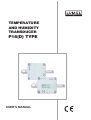
TEMPERATURE
AND HUMIDITY
TRANSDUCER
P18(D) TYPE
user’s mAnuAl
1
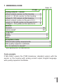
Contents
1. Application................................................................................ 5
2. Transducer set...................................................................... 7
3. Basic requirements, operational safety................... 7
4. Installation.............................................................................. 7
4.1. Way of fixing............................................................................ 7
4.2. External connection diagrams................................................. 9
5. Service...................................................................................... 11
5.1. Power-on messages of the P18D transducer . ..................... 11
5.2. Description of the P18D transducer readout field.................. 12
5.3. Functions of the P18D transducer capacitive button............. 13
5.4. Programming parameters menu of the P18D transducer...... 14
5.5. Functions of the P18(D) transducer....................................... 15
5.5.1. Calculated values............................................................... 16
5.5.2. Selection of controlling values for analog outputs.............. 16
5.5.3. Individual characteristic of analog outputs.......................... 17
5.5.4. Support of a sensor heater................................................. 19
5.5.5. Default settings................................................................... 20
6. RS-485 interface.................................................................... 21
6.1. Connection of the serial interface.......................................... 21
6.2. Description of the MODBUS protocol implementation........... 23
6.3 Description of the functions used........................................... 23
6.4 Map of the registers................................................................ 26
6.5 Registers for writing and readout............................................ 27
6.6 Registers for readout.............................................................. 33
6.7 Emergency restoration of default parameters........................ 36
7. Error codes........................................................................... 37
8. Accessories........................................................................... 38
9. Technical data...................................................................... 39
10. Ordering code..................................................................... 41
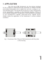
1. Application
The P18 and P18D transducers are the devices destined
for the continuous measurement and conversion of relative humidity
and ambient temperature into a digital form and into a voltage or current standard signal. The transducers are fixed on a wall. Programming
of the transmitters is possible via the RS?-485 interface. LPCon or
eCon software designed for configuration of the transducers is available
on the manufacturer’s website: www.lumel.com.pl. Applied sensor
shields enable the application of the transducers in various ambient
conditions.
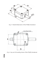
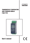
Fig. 1. Overview of the P18 and P18D transducers with the probe
on the housing.
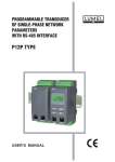
Fig. 2. Overview of the P18 and P18D transducers with the probe
on the wire 0,5 m.
2. Transducer set
− Transducer 1 pc
− User’s manual
1 pc
− Warranty card
1 pc
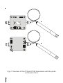
3. Basic requirements, operational safety
In terms of operational safety, the transducer meets
the requirements of the EN 61010-1 standard.
Comments concerning safety
•
Assembly and installation of the electrical connections should
conducted only by people authorised to perform assembly of electric devices.
•
Always check the connections before turning the transducer on.
•
The transducer is designed to installation and usage in the industrial electromagnetic environment.
4. Installation
4.1. Assembly
The P18(D) transducer is designed to be mounted on a wall by
means of a screw connection or glue without the loss of IP65 tightness.
The transducer housing is made of a self-extinguishing plastics. The transducer has screw connectors placed inside the transducer, which enable
the connection of external wires of 1 mm2 cross-section.
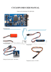
Fig. 3. Overall dimensions of the P18(D) transducer
mounting holes
Fig. 4. Lay-out of mounting holes of the P18(D) transducer
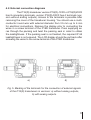
4.2. External connection diagrams
The P18(D) transducer version P18(D)-1XXX or P18(D)2XXX
has 8 connecting terminals, version P18(D)-0XXX has 4 terminals (version without analog outputs). Access to the terminals is possible after
removing the cover of the transducer housing. You should use a multiconductor round wire with external diameter from 3.5 mm up to 6 mm
for electrical connections. Remove the display prior to connecting the
wires in a screw terminal of the P18D transducer. Pass supplying wires through the packing and twist the packing seal in order to obtain
the leaktightness. If the packing seal is not twisted, the required IP 65
leaktightness is not ensured. The LCD display should be put back after
screwing the wires to the screw terminal of the P18D transducer.
a)
b)
Fig. 5. Marking of the terminals for the connection of external signals
of the P18(D) transducers in versions: a) without analog outputs,
b) with analog outputs.
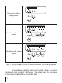
Transducer without
analog outputs
Transducer with current
outputs
Transducer with voltage
outputs
Out
1
Out
2
Out
1
Out
2
Fig. 6. Wiring diagram of the P18(D) transducer with analog outputs
Use shielded cable for supply and output signals in environments with high levels of interference. The shield must be connected
to the nearest PE point from the feeder side.
10
5. Service
The P18D transducer is equipped with a display field
8x2 characters with illumination and one capacitive button located
on the housing. The P18 transducer is not equipped with a display
or a button. After connecting the wires, closing and servicing
the housing, and connecting to the supply, the transducer is ready
to work with manufacturer’s settings (Tab. 4). The transducer can be
programmed through the RS-485 interface. You can program following
parameters in the transducer:
− communication parameters
− -averaging time of the measurement
− -individual characteristics of analog outputs (for executions with
analog outputs).
The P18D transducers allow programming communication parameters (address, baud rate, mode) using the capacitive button.
There is the possibility to connect the transducer through another transmission media, like: ETHERNET, USB using LUMEL S.A.’s converters.
5.1. Power-on messages of the P18D transducer
After connecting the external signals and connecting
to the supply, the transducer displays the type, current program version,
serial number and set communication parameters (address, baud rate
and operating mode).
The transmitter automatically switches to the operating mode of measurement and processing the analog output signal after approx. 5 seconds. It displays the measuring value with the unit in the bottom line
of the display, the top line of the display contains information about the
type of displayed quantity and the pictograms of: transmission via RS485, the presentation mode of the measuring value, the read pointer of
the measuring value of the sensor and the operating state of the internal
heater.
11
5.2. Description of the P18D transducer readout field
The illuminated character LCD is a readout field in the transducer P18D. The illumination is turned on after switching on the supply
and after the capacitive button on the housing is pressed. The illumination is automatically switched off after 30 sec. of inactivity.
Indicator of the measuring value
from the sensor
Type of the displayed value
Indicator of automatic presentation of the measuring values
Transmission
RS-485 link
Value of the displayed
value
indicator
on
Unit of the displayed
value
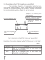
Fig. 7. Description of the P18D transducer readout field
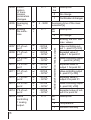
Description of the symbols displayed by the P18D transducer is in the Table 1.
Table 1
12
Symbol
Meaning
T:
Type of the displayed value in the bottom line
of the LCD - temperature
RH:
Type of the displayed value in the bottom line
of the LCD - relative humidity
DP:
Type of the displayed value in the bottom line
of the LCD - dew-point
AH:
Type of the displayed value in the bottom line
of the LCD - absolute humidity
The indicator of the measuring value from the sensor
Automatic mode of measurement results presentation
- a type of displayed value is automatically switched
every 3 seconds in the following order: temperature →
relative humidity → dew-point → absolute humidity →
temperature ….
Data receiving indicator by the P18D transducer
on RS-485
Data sending indicator by the P18D transducer
on RS-485
h
Switching on the internal heater indicator to dry
the sensor
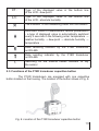
5.3. Functions of the P18D transducer capacitive button
The P18D transducers are equipped with one capacitive
button located on the housing. The location of the button shows in Fig. 8.
Fig. 8. Location of the P18D transducer capacitive button
13
Capacitive button is used to:
• switch the display illumination on
• change the presentation mode of the measurement results holding the button for about 2 seconds switches from automatic
mode to manual mode or inversely
• change the type of displayed values in the manual mode of presentation of the measurement results - pressing the button for a short
time changes the displayed value.
• program communication parameters (address, baud rate, mode)
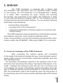
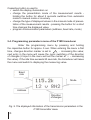
5.4. Programming parameters menu of the P18D transducer
Enter the programming menu by pressing and holding
the capacitive button for approx. 5 sec. When entering the menu a first
time, changes direction marker is set to
- increasing the value;
next entry in the menu will cause the cyclic switching of the direction
of changes (2 input in the menu will set the marker at v – decreasing
the value). If the idle time exceeds 20 seconds, the transducer will leave
the menu and switch to displaying the measuring value.
Baud
rate
Mode
Address
Direction
of changes
Fig. 9. The displayed information of the transmission parameters in the
P18D transmitter menu
14
Confirmation
of changes
5 seconds
Measurement
Application
of changes
5 seconds
5 seconds
Mode programming
Baud rate programming
increase/
decrease
the value
Address programming
5 seconds
5 seconds
increase/
decrease
the value
increase/
decrease
the value
decreasing the value
increasing the value
Fig. 10. Programming parameters algorithm of the P18D transducer
5.5. Functions of the P18(D) transducer
The P18(D) transducer carries out the functions:
• measurement of the ambient temperature and relative humidity
• calculation of chosen physical quantities (dew-point temperature,
absolute humidity, wet bulb temperature)
• conversion of measured values into an output signal on the base
of the individual linear characteristic (2 configurable analog outputs
- optional)
• memory storage of maximal and minimal values for each
of the measured and calculated value
• programming of the measurement averaging time
• RS-485 interface servicing in the MODBUS protocol, in RTU
mode.
• Displaying measuring and calculated values (only P18D)
15
5.5.1. Calculated values
Based on the measurement of a temperature and relative
humidity, the P18D transducer calculates dew-point and absolute humidity of the following dependencies.
Tn
m
DP =
DP → dwe-point:
(
log Pws
10000 A
AH = 2,1668
DP → absolute humidity:
-1
RH
)
Pws RH
100 (T + 273,2)
gdzie:
T → measured temperature [oC]
RH → measured absolute humidity [%]
DP → dew-point temperature [oC]
Pws → saturated water vapor pressure (water vapor pressure) [mbar]
AH → absolute humidity [g/m3]
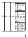
Table 2
The factors used to calculate the dew-point
T [oC]
A
m
Tn
<0
6.119866
7.926104
250.4138
0...50
6.1078
7.5
237.3
50...100
5.9987
7.3313
229.1
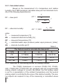
5.5.2. Selection of controlling values for analog outputs
The P18(D) transducers in versions P18(D)-1XX, P18(D)2XX, P18(D)-4XX, P18(D)-5XX are equipped with two programmable
analog outputs (voltage or current). By default, the first analog output
is set for a presentation of the ambient temperature and the second
analog output is controlled by the value of the relative humidity. The analog outputs can respond to any of the measuring or calculated values
16
(T, RH, DP, AH, wet bulb temperature). The value controlling the analog
outputs is defined by the registers, respectively 4015 for the first output
and 4016 for the second analog output (Tab. 14).
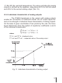
5.5.3. Individual characteristic of analog outputs
The P18(D) transducers in the version with analog outputs
enable the conversion of measured values into an output signal based on the strength of individual linear characteristic of analog outputs.
On the base of given coordinates of two points by the user, the transducer determines (from the system of equations) coefficients a and b
of the individual characteristic.
where:
{
Y1out = a X1in + b
Y2out = a X2in + b
X1 in and X2 in - displayed value,
Y1 out and Y2 out - oexpected value of the analog output
Fig. 11. Individual characteristic of analog output
17
The configuration of the individual characteristic of analog
outputs amounts to the introduction of suitable values X1, X2, Y1, Y2
in corresponding registers to them from the range 4007 – 4014 Tab. 3.
The values introduced in these registers must be integral values corresponding to the set point values multiplied by the value 100.
Example 1
Configuration of the individual characteristic of the first analog current
output (temperature):
Expected processing temperature in the range -12,25oC ÷ 77,75 oC
to the analog current signal in the range 4,5 mA ÷ 18,5 mA.
Table 3
Name
Register address
Value
X1 temperature
4007
-1225
Y1 current
4008
450
X2 temperature
4009
7775
Y2 current
4010
1850
Caution:
The analog outputs are not isolated from the supply,
the RS-485 interface and each other, the analog current outputs don’t
have a common potential (low potential terminals can not be connected together), analog voltage outputs have a common low potential
(low potential terminals can be connected together).
18
5.5.4. Support of a sensor heater
The sensors used in the P18(D) transducers are equipped
with internal heating elements to allow faster release of water molecules from the sensor being flooded or working a long time in highly humid environments. Switching the heater on is possible by writing the
appropriate value to the register 4021 (see Tab. 14). Status of the heater
is available in the status register (register 4017) at the bit position 11
(if the bit 11 of the register 4017 is set to „1” - this means that the heater
is switched on).
Caution:
The transducer with a heating element switched on does not measure
the proper ambient temperature and humidity! (the temperature measured by the sensor increases and the humidity decreases). The value
200 is added to the measuring values (temperature, relative humidity)
when using the transducer with the heater switched on in order to avoid
distortions of a measurement in the measurement systems!
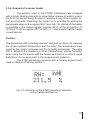
The P18D transducers working with a heating element switched on display a flashing symbol h.
Fig. 12. Indication of the P18D transducer operation
with a heater switched on
19
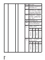
5.5.5. Default settings
The Table 4 shows the standard settings of the P18D transducer. The settings can be restored via the RS-485 interface after writing
the value „1” to the registry 4020.
Table 4
Parameter
description
Parameter
address
Standard value
P18D-0XX,
P18D-3XX
P18D-1XX,
P18D-4XX
P18D-2XX,
P18D-5XX
Address
4001
1
Baud rate
4002
9600
Mode
4003
RTU 8N2
Averaging time
4005
30 [s]
X1 of the 1st
analog output
4007
0
-2000
-2000
Y1 of the 1st
analog output
4008
0
400
0
X2 of the 1st
analog output
4009
0
6000
6000
Y2 of the 1st
analog output
4010
0
2000
1000
X1 of the 2nd
analog output
4011
0
0
0
Y1 of the 2nd
analog output
4012
0
400
0
X2 of the 2nd
analog output
4013
0
10000
10000
Y2 of the 2nd
analog output
4014
0
2000
1000
20
Value controlling the first
analog output.
4015
0
0
0
Value controlling the second
analog output.
4016
1
1
1
Custom configuration
4019
8
8
8
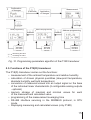
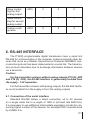
6. RS-485 interface
The P18(D) programmable digital transducers have a serial link
RS-485 for communication in the computer systems and with other devices that serve as a Master. Asynchronous character MODBUS communication protocol has been implemented in a serial link. The transmission protocol describes how to exchange information between devices
via a serial link.
Caution:
For the transmitter versions without analog outputs (P18 (D) -0XX
and P18 (D) -3XX), the RS-485 interface is galvanically isolated from
the supply - 1 kV separation.
For the transmitter versions with analog outputs, the RS-485 interface is not isolated from the supply or from the analog outputs.
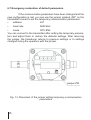
6.1. Connection of the serial interface
Standard RS-485 allows a direct connection up to 32 devices
on a single serial link to a length of 1200 m (at baud rate 9600 b/s).
It is necessary to use additional intermediate-separation circuits for connecting higher number of the devices, for example PD51 manufactured
by LUMEL S.A.
21
Output of the interface line is shown in Fig. 6. It is required to connect the lines A and B in parallel with their equivalents in other devices
to obtain the correct transmission. The connection must use a shielded
wire. The cable shield should be connected to the protective terminal
in close proximity to the transmitter (connect a shield to the protective
terminal at one point only).
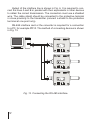
RS-485 interface card or the converter is required for a connection
to a PC, for example PD10. The method of connecting devices is shown
in Fig. 13.
Fig. 13. Connecting the RS-485 interface.
22
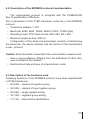
6.2. Description of the MODBUS protocol implementation
The implemented protocol is compliant with the PI-MBUS-300
Rev G specification of Modicon.
Set of parameters of the P18D transducer serial link in the MODBUS
protocol:
• Transducer address 1..247.
• Baud rate: 4800, 9600, 19200, 38400, 57600, 115200 [b/s].
• Operating mode: RTU frame format: 8N2, 8E1, 8O1, 8N1.
• Maximum response time: 500 ms
Configuration of the serial link parameters consists of determining
the baud rate, the device address and the format of the transmission
mode - protocol.
Caution: Each transmitter connected to the communication network must:
• have a unique address, different from the addresses of other devices connected to the network.
• Identical baud rate and type of a transmission mode
6.3 Description of the functions used
Following functions of the MODBUS protocol have been implemented
in P18D transducers:
• 03 (03h) – readout of registers group,
• 04 (04h) – readout of input registers group,
• 06 (06h) – single register writing,
• 16 (10h) – registers group writing,
• 17 (11h) – slave device identification.
23
Readout of n-registers (code 03h)
Example 1. Readout of 2 registers, starting with the register address
1D4Dh (7501) float (32-bit), (register values 25.68, 20.25.)
Request:
Table 5
Device
address
Function
01h
03h
Register address
Number of registers
B1
B0
B1
B0
1Dh
4Dh
00h
02h
CRC checksum
5270h
Response:
Table 6
Value from the register
1DB0 (7501)
Value from the register
1DB1 (7502)
Device
address
Function
Number of
bytes
b3
b2
b1
b0
b3
b2
b1
b0
CRC
checksum
01h
03h
08h
41h
CDh
70h
A4h
41h
A2h
00h
00h
83D0h
Single register writing (code 06h)
Example 2. Writing the value 78h (120) to the register FA1h (4001)
Request:
Table 7
Device
address
Function
01h
06h
Register address
Register value
B1
B0
B1
B0
0Fh
A1h
00h
78h
Response:
DB1Eh
Table 8
Device
address
Function
01h
06h
24
CRC
checksum
Register address
Register value
B1
B0
B1
B0
0Fh
A1h
00h
78h
CRC
checksum
DB1Eh
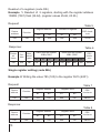
Writing n-registers (code 10h)
Example 3. Writing the value 78h (120) and the value 4h (4) to the registers FA1h, FA2h (4001, 4002)
Table 9
Request:
Device
address
Function
01h
10h
Register
address
0Fh
A1h
Number of
registers
00h
78h
Number of
bytes
04h
Register
value
4001
Register
value
4002
B1
B0
B1
B0
CRC
checksum
00h
78h
00
04
F831h
Table 10
Response:
Device
address
Function
01h
10h
Register address
Number of registers
B1
B0
B1
B0
0Fh
A1h
00h
02h
CRC
checksum
133Eh
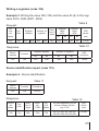
Device identification report (code 11h)
Example 4. Device identification
Request:
Table 11
Device
address
Function
Checksum
01h
11h
C02Ch
Response:
Device
address
01h
Table 12
Function
Number of
bytes
Identifier
P18D
Device
status
The field depending on the
device software version
(e.g. 0.70)
CRC
checksum
11h
0Eh
CCh
FFh
50h 31h 38h 44h 76h 2Eh
30h 2Eh 30h 34h 20h 00h
B154h
25
6.4 Map of the registers
In the P18D transducer, data are placed in 16 and 32-bit
registers. Process variables and transducer parameters are placed
in the address area of registers in a way depended on the variable
value type. Bits in 16-bit registers are numbered from the youngest
to the oldest (b0 … b15). The 32-bit registers (4 bytes) contain numbers
of float type in IEEE-754 standard. Bytes sequence: B3 B2 B1 B0 –
the oldest byte is transmitted as the first.
A following map is the map of P18(D) transducers registers.
Caution:
All listed addresses are physical addresses. Some computer programs
use logic addressing, then the addresses should be increased by 1.
Table 13
Address
range
Value type
4000-4022
integer
(16 bits)
6000-6030
float (32 bits)
Value set in the two following 16-bit
registers. These registers contain the same
data as 32-bit registers from 7500-7515
range. Readout registers. Bytes sequence
(B1,B0,B3,B2)
7000-7030
float (32 bits)
Value set in the two following 16-bit
registers. These registers contain the same
data as 32-bit registers from 7500-7515
range. Readout registers. Bytes sequence
(B3,B2,B1,B0)
7500-7515
float (32 bits)
The value is located in the 32-bit register.
Registers contain measured and calculated
data by the transducer. Registers are only
for readout.
26
Description
The value is located in the 16-bit register.
Table 14
The value is located
in the 16-bit registers
Write (w) / readout (r)
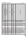
6.5 Registers for writing and readout
Name
4000
Identifier
w/
r
180
P18 device identifier
204
P18D device identifier
4001
Address
w/
r
1...247
4002
RS-485
baud rate
4003
RS-485
transmission mode
Range
0...5
0...3
Description
Device address
Value
Description
0
4800 bit/s
1
9600 bit/s
2
19200 bit/s
3
38400 bit/s
4
57600 bit/s
5
115200 bit/s
Value
Description
0
RTU 8N1
1
RTU 8N2
2
RTU 8E1
3
RTU 8O1
27
Confirmation
of transmission
parameters
changes
0...1
4005
Averaging
time
w/
r
6...3600
4006
Erasing
the extremes
w/
r
0...1
4007
X1 of output 1
w/
r
-32768
...32767
4008
Y1 of output 1
w/
r
-32768
...32767
4009
X2 of output 1
w/
r
-32768
...32767
4010
Y2 of output 1
w/
r
-32768
...32767
4011
X1 of output 2
w/
r
-32768
...32767
4012
Y1 of output 2
w/
r
-32768
...32767
4013
X2 of output 2
w/
r
-32768
...32767
4014
Y2 of output 2
w/
r
-32768
...32767
4015
Value
controlling
1 analog
output.
w/
r
0...3
28
Value
Description
0
No change
1
Confirmation of changes
Averaging time of the measurement [s]
Value
Description
0
No change
1
Erasing the min. and
max. values
Individual characteristic of analog outputs
4004
Value
Value controlling output 1 - point X1[ x100]
Expected value of
output 1 for point X1
Value controlling output
1 - point X2 [ x100]
Expected value of
output 1 for point X2
Value controlling output
2 - point X1 [ x100]
Expected value of
output 2 for point X1
Value controlling output
2 - point X2 [ x100]
Expected value of output 2 for point X2
Description
0
Temperature
1
Relative humidity
4016
4017
Value
controlling
2 analog
output.
Status
w/
r
w/
r
0...3
-32768
...32767
2
Dew-point
3
Absolute humidity
4
Wet bulb temperature
Value
Description
0
Temperature
1
Relative humidity
2
Dew-point
3
Absolute humidity
4
Wet bulb temperature
Transducer status. Shows
the current state of the transducer and the hardware configuration. Successive bits
represent the event. Bit set
to 1 indicates that the event
took place.
Bit15
Restart of the supply, writing the value
-32768 (8000h) will
clear the status bit
Bit14
Error of the calibration parameters
Bit13
Error of the transmitter settings - enter the
new settings
29
Bit12
not used
Bit11
Indicator of switching
the heater on
Bit10
Indicator of erasing
the extremes, writing
the value 1024 (400h)
erases the status bit
Bit9
Temporary communication parameters
are set (shorten jumper „ZW”)
Bit8
LCD display error
Bit7
Error reading the value from the sensor
Bit5,
6
Value controlling 2
analog output
30
11
absolute humidity
dew-point
10
00
01
10
11
relative humidity
dew-point
absolute humidity
Value controlling 1
analog output
temperature
Bit3,
4
01
relative humidity
temperature
00
4018
Software
version
o
1...999
4019
Custom
configuration
w/
r
0...31
Bit2
results averaging interval has ended
Bit1
The transducer is equipped with the analog
outputs - voltage.
Bit0
The transducer is equipped with the analog
outputs - current.
Software version x100
Bit0
Bit1
...4
Value
Description
0
The standard map
of the registers in
the range
7000 and
7500
1
Map
of
the registers in
the range 7500
and 7000
compliant
with the
map
of
the P14W
transducers
Number of characters
of a response delay
to the query for the
RS-485 transmission
31
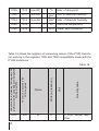
4020
4021
Default
settings
Controlling
the heater
w/
r
0...1
Value
Description
0
no change
1
przywraca parametry
fabryczne
Value
0
switching a heater off
1
permanent switching
a heater on
3
displaying remaining
time of a heater switched on
60
...
switching a heater on
for Xn seconds (Xn value from the range
60...32768 )
32768
4022
32
reserved
Description
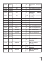
6.6 Registers for readout
Name
Write (w)/ readout (r)
7500
ID
r
7002
7501
T
r
o
C
Measured temperature
7004
7502
RH
r
%
Measured relative humidity
7006
7503
DP
r
o
7008
7504
AH
r
g/m
7010
7505
min T
r
o
C
Min. of temperature
7012
7506
max T
r
o
C
Max. of temperature
7014
7507
min RH
r
%
Min. of relative humidity
7016
7508
max RH
r
%
Max. of relative humidity
7018
7509
min DP
r
o
Min. of dew-point
-
P18(D) device identifier
C
Calculated dew-point
3
C
Quantity name
The value is located in the
32-bit registers
7000
Unit
Value set in the two following 16-bit registers.
Registers contain the same data as 32-bit registers
from the area 7500.
Table 15
Calculated absolute humidity
33
7020
7510
max DP
r
7022
7511
min AH
r
g/m3
Min. of absolute humidity
7024
7512
max AH
r
g/m3
Max. of absolute humidity
7026
7513
r
7028
7514
r
o
C
Max. of dew-point
C
Wet bulb temperature
kPa
Water vapor pressure
o
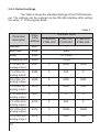
Table 16 shows the registers of measuring values of the P18D transducer working in the registers 7000 and 7500 compatibility mode with the
P14W transducer
7500
ID
34
o
-
Quantity name
7000
Unit
The value is located in the
32-bit registers
Name
Write (w) /readout (r)
Value set in the two following 16-bit registers. Registers contain the same data as 32-bit registers
from the area 7500.
Table 16
P18(D) device identifier
7002
7501
T
o
o
C
Measured
ture
7004
7502
DP
o
o
C
Calculated dew-point
7006
7503
-
-
-
7008
7504
RH
o
%
Measured
humidity
relative
7010
7505
AH
o
g/m3
Calculated
humidity
absolute
7012
7506
-
-
-
7014
7507
-
-
-
7016
7508
-
-
7018
7509
min T
o
C
Min. of temperature
7020
7510
max T
o
C
Max. of temperature
7022
7511
min DP
o
C
Min. of dew-point
7024
7512
max DP
o
C
Max. of dew-point
7026
7513
-
-
-
7028
7514
-
-
-
7030
7515
min RH
o
%
Min. of relative
humidity
7032
7516
max RH
%
Max. of relative
humidity
7034
7517
min AH
g/m3
Min. of absolute
humidity
7036
7518
max AH
g/m3
Max. of absolute
humidity
o
o
o
tempera-
-
35
6.7 Emergency restoration of default parameters
If the communication parameters have been changed and the
new configuration is lost, you can use the jumper marked „ZW” on the
transmitter’s board to set the temporary communication parameters:
address 247
•
•
baud rate •
modeRTU 8N2
9600 kb/s
You can connect to the transmitter after setting the temporary parameters and adjust them or restore the defaults settings. After removing
the jumper, the transducer returns to previous settings or to settings
changed during the operation with the jumper.
jumper ZW
Fig. 13. Placement of the jumper setting temporary communication
parameters
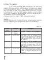
36
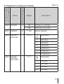
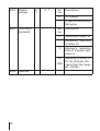
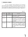
7. Error codes
The error messages could be displayed on the transducer
P18D display during operation. The table below lists the error codes
which are possible to be displayed and their reasons as well as the
recommended user responses. Information about the existing errors is
also available in the P18(D) transducers status register - register 4017.
Table 17
Message
bit no.
reg. Status
(reg. 4017)
Error
Sensor
7
Sensor failure - transmitter should be
returned to a service
Error
Calibr.
14
Loss of calibration parameters - loss
of efficiency of the analog outputs,
measurements are correct - returning
a transmitter to a service should be
considered
Error
Param.XX
13
Loss of transmitter settings - XX
- number of a parameter (register
number 40XX) configured incorrectly
- correct value should be written to
the register 40XX or default settings
restored
Description
37
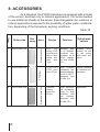
8. Accessories
As a standard, the P18(D) transducer is equipped with a shield
of the sensor, destined only for indoors applications. It is recommended
to use additional shields of the sensor (interchangeable) for outdoors or
indoors applications exposed to the possibility of water vapor condensation, depending of the transducer working conditions.
Table 18
0874-490-016
2
0874-490-015
3
0874-490-014
38
Typical applications
Name
Design
Features
Membrane filter
1
Drawing
PCV
housing, PTFE
membrane
with a laminated film,
pore size:
1 µm
Average effect of filtration,
maximal temperature: up to
80oC, response time t10/90:
15 s
Building automation, for use
in the rooms
with small pollution
Sintered
PTFE, pore
size 50 µm
High chemical
resistance, maximal temperature: up to 180 oC,
response time
t10/90:14 s
Drying process
in chemical applications
Sintered
bronze,
pore size
60 µm
High mechanical resistance,
used in high
pollution
and
low
humidity,
response time
t10/90: 10 s
Agriculture
Sintered bronze filter
PTFE filter
Item
Order code
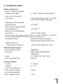
6. Technical data
Basic parameters:
- range of relative humidity measurement (RH)
0...100%, without condensation1)
- basic error of humidity conversioni
± 2% of the range for RH = 10...90%
± 3% for the remaining range
- hysteresis of the humidity measurement
± 1% RH
- basic range of temperature measurement (T)
-20...60°C 2)
- basic error of temperature conversion
± 0.5% of the range*
* for the versions with analog outputs P18(D)-1, P18(D)-2, P18(D)-4 or P18(D)-5,
a basic error of temperature conversion may increase by 0.2°C
- calculated values
- additional errors:
- temperature influence
RS-485 digital output:
- transmission protocol
- baud rate
- mode
- max. response time
absolute humidity (a) [g/m3]
dew-point temperature (Td) [oC]
± 25% of the basic error /10°C
MODBUS
4800, 9600,19200,38400,
57600 bit/s
RTU: 8N2, 8E1, 8O1, 8N1
300 ms
Analog outputs:
- current
4...20 mA
- voltage
0...10 V
- max. load resistance of the current output 100 W
- min. load resistance of the voltage output
1 kW
39
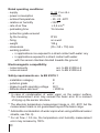
Rated operating conditions:
- supply
9...24 V a.c./d.c.
- power consumption
< 0.5 VA
- ambient temperature
- 20...23...60oC
- relative air humidity
< 95% 3)
- rate of air flow 0,5 m/s 4)
- preheating time 15 minutes
- protection grade ensured
by the housing
IP 65
- fixing
on a wall
- weight
125 g
- dimensions
(35 ´ 58 ´ 118) mm
- working position:
• in applications non-exposed to a direct contact with water: any
• in applications exposed to a direct contact with water:
with the sensor chamber directed towards the ground
Electromagnetic compatibility:
- noise immunity
- noise emission
acc. to EN 61000-6-2
acc. to EN 61000-6-4
Safety requirements acc. to EN 61010-1
- installation category
- pollution grade
- phase-to-earth operating voltage
- altitude above sea level
III
2
50 V
< 2000 m
In case of condensation of water vapor on the sensor surface,
the measurement error may exceed the basic error till a moment
of drying up the sensor structure
1)
2)
The absolute temperature measurement range is –30...85oC but the
measurement class is not guaranteed beyond the basic range
3)
Admissible condensation of water vapor when using additional sensor
shields, see Tab. 9)
4)
For air flow < 0.5 ms, the temperature and humidity measurement
error may increase by 100%.
40
7. Ordering code
Table 10
P18(D) - X XX X X
Analog outputs - sensor:
without outputs, sensor on the housing
current 4...20 mA, sensor on the housing
voltage 0...10V, sensor on the housing
without outputs, probe on the wire 0,5 m
current 4...20 mA, probe on the wire 0,5 m
voltage 0...10V, probe on the wire 0,5 m
Version:
standard
custom-made*
Language:
Polish
English
other*
Acceptance tests:
Without extra quality requirements
With quality inspection certificate
Acc. to customer’s request*
* after agreeing with the manufacturer
0
1
2
3
4
5
00
XX
P
E
X
0
1
X
Code example:
P18D-100E1 means the P18D transducer, standard version with the
sensor on the housing with analog current output, English language,
with quality inspection certificate.
41
42
43
LUMEL S.A.
ul. Słubicka 1, 65-127 Zielona Góra, Poland
Tel.: (48-68) 45 75 100
Fax: (48-68) 45 75 508
e-mail:[email protected]
http://www.lumel.com.pl
Export Department:
Tel.: (48-68) 45 75 302
Fax: (48-68) 32 54 091
e-mail: [email protected]
44
P18-09C