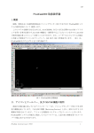
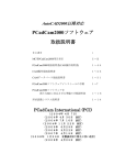
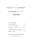
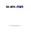
1
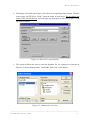
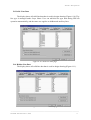
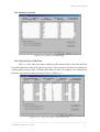
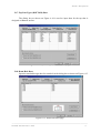
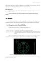
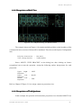
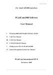
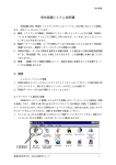
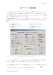
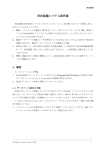
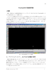
Feature Recognition
VI
Feature Recognition System User Manual
This chapter will explain the installation procedure and operation example of feature
recognition CAD (FRCAD) software. The explanation on how to use the software is covered in
Chapter II Section 6. This chapter will cover the following:
6.1. Outline: The installation procedure and structure of the software. FRCAD software is
supplied merged with PCadCam2000 software; however user has to install the software
independently.
6.2. Drawing Database Registration: The procedure to register data into drawing database to
prepare FRCAD operation on two-dimensional CAD system that the user used.
6.3. Examples: Several examples will be presented.
6.1. Outline
This section will describe the preparation for FRCAD software installation. There are
two important files to run FRCAD: fr.arx and frcad.mdb; and these two files will be set
automatically when user installs PCadCam2000 to C:\Program Files\PCadCam folder.
The following section will describe the method to install FRCAD database.
6.1.1.
6.1.1. Connecting
Connecting Database
FRCAD is operational in database administration system using Microsoft Office
ACCESS software. The database is connected via ODBC application, which is included
automatically when installing Microsoft WINDOWS operating system. User can also
download ODBC application from Microsoft.com.
Perform the following operation to set ODBC:
1. Open Control Panel to bring up a display as shown on Figure 6-1. Depends on the
operating system; ODBC maybe be located in control system under administrative tool.
―――――――――――――――――――――――――――――――――――――――――――――
PCadCam International (PCI)
1
Feature Recognition
Figure 6-1. ODBC display from Windows Control Panel
2. Click on the ODBC icon and the display is switched as Figure 6-2 to display the ODBC
data source administrator. Click on “Add” button.
Figure 6-2. ODBC data source administrator
3. Figure 6-3 will show the next dialog box to select database driver. Select Microsoft
Access Driver then click on “FINISH” button.
Figure 6-3. Selection on database driver
―――――――――――――――――――――――――――――――――――――――――――――
PCadCam International (PCI)
2
Feature Recognition
4. The display will switch into Figure 6-4 for the user to input Data Source Name. The data
source name for FRCAD is “frcad”. Input the name in small letter. Do not change the
name or FRCAD will not run. User can input any description in the lower column. Click
on “Select” button.
Figure 6-4. Data source input display
5. The system will then ask user to select the database file via a dialog box as shown on
Figure 6-5. Select database name “frcad.mdb” then click on OK button.
Figure 6-5. Database file selection
―――――――――――――――――――――――――――――――――――――――――――――
PCadCam International (PCI)
3
Feature Recognition
6. Upon completion of step 1 to 5; the display will return to the first display with an
additional “frcad” added in the User Data Sources as shown on Figure 6-6. User should
confirm that FRCAD exists on the list. Click on OK then exit Control Panel.
Figure 6-6. Data Sources “frcad” addition
6.2. Drawing Database Registration
This section will explain the method to register the important data into drawing
database based on the rule on how the user creates their design drawing using CAD system.
1. Start PCadCam software and click on FR Database icon in FR toolbar as shown on Figure
6-7.
FR Database
Figure 6-7. FR Database icon
2. The drawing database dialog box will be displayed as shown on Figure 6-8. There are nine
data page on the dialog box, and the display shows tap data page.
―――――――――――――――――――――――――――――――――――――――――――――
PCadCam International (PCI)
4
Feature Recognition
3. The complete type of tap, including pipe screw (PT type), that is used in the design
drawing is registered in.
B.1. Tap Data
Figure 6-8. Tap data page
B.2. Counter Bore Data
Input the standard design data for counter bore
Figure 6-9. Counter Bore data page
―――――――――――――――――――――――――――――――――――――――――――――
PCadCam International (PCI)
5
Feature Recognition
B.3 Solid Line Data
The display shows all solid line data that is used in design drawing (Figure 6-10). The
line type is managed under Layer Name. User can add this line type data during FRCAD
operation automatically, and the same case applies on hidden and auxiliary lines.
Figure 6-10. Solid line data page
B.4. Hidden Line Data
The display shows all solid line data that is used in design drawing (Figure 6-11).
Figure 6-11. Hidden line data page
―――――――――――――――――――――――――――――――――――――――――――――
PCadCam International (PCI)
6
Feature Recognition
B.5. Auxiliary Line Data
Figure 6-12. Auxiliary line data page
B.6. Tap Line Types (TOP) Data
There is a case when tap exists on both top and bottom surfaces. The data describes
herewith regulates the tap hole design on top surface. There are two concentric line symbols for
each tap drawn: the tap (Tap LT) and the under hole (Un-Hole LT) symbols. User should fill in
the name, type and color data on each as shown on Figure 6-13.
Figure 6-13. Tap Line Types (TOP) data page
―――――――――――――――――――――――――――――――――――――――――――――
PCadCam International (PCI)
7
Feature Recognition
B.7. Tap Line Types (BOTTOM) Data
The dialog box as shown on Figure 6-14 is used to input data for the tap that is
designed on Bottom surface.
Figure 6-14. Tap Line Type (BOTTOM) data page
B.8. Ream Hole Data
Input the standard design data for ream hole in the dialog box as shown on Figure 6-15.
Figure 6-15. Ream Hole data page
―――――――――――――――――――――――――――――――――――――――――――――
PCadCam International (PCI)
8
Feature Recognition
B.9. System Configuration Data
User will conduct system setting based on the data supplied in the dialog box as shown
on Figure 6-16.
Figure 6-16. System Configuration data page
System Mode:
It is a toggle box to select an automatic recognition of the imaginary workpiece
boundary or thru interaction mode for each projection view in the case when FR system has to
run on three projection views. Select on “Automatic” for an automatic recognition process.
Select “Interactive” for the user to input the data interactively on a dialog box. If the user select
“Automatic” but the system fails to run the designated function; the system will switch into
“Interactive” promptly.
Non-Tangent Arcs in Contour:
It is a toggle box to assign the selection on the inclusion of angle (non-tangent) in
polyline. The polyline itself may consist of arc and arc, arc and straight line, or straight line to
and straight line. There is a case when angle exists in between the lines, therefore user has to
decide whether to include the angle as a different machining feature or it is included in the
polyline itself.
―――――――――――――――――――――――――――――――――――――――――――――
PCadCam International (PCI)
9
Feature Recognition
Pre-Processor:
This toggle box will allow the user to activate segment subdivision response in
between projection views for a significant automatic looping when dealing with running FR on
three projection views. The function will not be run on ONE VIEW operation.
Local Origin Point Method:
This toggle box is used to assign the origin on each design surface of a workpiece.
“Based on Global Origin Point" means that the origin point on each of design surface is a
projection of the origin point on the workpiece. “Lower-Right Corner” means that the origin
point will always be on the lower right corner for each design surface. Both selections apply the
right hand rule. Based on Global Origin Point is the default option.
AutoCAD Link:
Set the toggle into “Active” mode so that FRCAD system can download a DXF file
automatically when the user clicks on “INPUT DXF FILE” in the earlier stage of PCadCam
operation. At that time the DXF file name will be “acad2frcad.dxf” and it should be located in
C:\Program Files\PCadCam folder.
Polyline Generation:
Set the toggle to allow FRCAD to process any polyline exists in the design drawing. In
such a case, FRCAD will generate a DXF file that contains a polyline (or more). It is also
possible to process the generated DXF file by PCadCam later on.
View, Design Surface:
Set this toggle box to perform recognition for the ONE VIEW projection so that either
the operation will be done only on the visible surface (Visible Surface), or the hidden surface
(Hidden Surface) or both visible and hidden (Visible & Hidden Surfaces). The default will be
“Visible & Hidden Surfaces”, and in this setting; the feature recognition process will be done on
front and back surfaces.
Edit Feature:
It is necessary for the user to correct machining feature data after automatic
recognition operation by FR system. The manual correction may be done only in PCadCam or
FRCAD.
Tolerance Values:
The value set on the left side (radius, mm) is an allowable error on connectivity,
tangency, normal and parallel between the starting and end points of segment data exists in a
DXF file. The value on the right is the allowable error (unit mm) on the difference of standard
―――――――――――――――――――――――――――――――――――――――――――――
PCadCam International (PCI)
10
Feature Recognition
value for tap data and the actual tap diameter on the drawing. Set the accuracy value by
adjusting it to the drawing will undergo feature recognition process.
FRCAD Directory:
Input the directory where PCadCam2000 software is located, usually it is set to C:\
Program Files\PCadCam.
Click on “OK button once all the nine data have been completed, then close the
window.
6.3. Examples
It is necessary to revise the setting based on the type of drawing will undergo feature
recognition operation. The following section will present several examples of the operation.
6.3.1. Recognition on One View with Polyline
Set the following into System Configuration of Figure 6-16.
Polyline Generation :Set to “Active” for automatic recognition on polyline.
V i e w , D e s i g n : Set to “Visible Surface” to run recognition only on the front surface or set on
S u r f a c e “Visible & Hidden Surfaces to run recognition on both the front and back
surfaces.
Select “CONVENTIONAL ONE VIEW” on the dialog box after clicking on feature
recognition icon to start the operation. Input the “Material Thickness” data accordingly.
Figure 6-17. Example drawing for ONE VIEW projection with Polyline
―――――――――――――――――――――――――――――――――――――――――――――
PCadCam International (PCI)
11
Feature Recognition
6.3.2
6.3.2. Recognition on Multi View
Figure 6-18. Example drawing for MULTI-VIEW
The example shown on Figure 6-18 contains multiple polyline on the boundary of the
cast material; however none of them will be machined. Therefore set the System Configuration
into:
Polyline Generation : Not Active
View, Design Surface : Visible Surface
Select “MULTI- VIEW PROCESS” on the dialog box after clicking on feature
recognition icon to start the operation. Assign the following surface design name for each
projection:
Upper
Right :
Projection
Upper
Left :
Projection
Bottom
Left :
Projection
LEFT
BACK
TOP
Refer to Chapter II Figure 2-18 to assign a name on projection view.
6.3.2
6.3.2. Recognition on Third Quadrant
In this example; the operation will zoom three projection views from the RIGHT View
―――――――――――――――――――――――――――――――――――――――――――――
PCadCam International (PCI)
12
Feature Recognition
of the drawing that is positioned on the right bottom as shown on Figure 6-19. Set the following
into System Configuration:
P r e -P r o c e s s o r :
Polyline Generation :
Active
Not Active
Select “MULTI- VIEW PROCESS” on the dialog box after clicking on feature
recognition icon to start the operation.
Figure 6-19. Example drawing for THIRD QUADRANT
―――――――――――――――――――――――――――――――――――――――――――――
PCadCam International (PCI)
13