1
SeaOWL UV-A150901
SeaOWL UV-A
User manual
09/2015, Edition 1
Table of Contents
Section 1 Specifications .................................................................................................................... 3
1.1 Mechanical................................................................................................................................... 3
1.1.1 6-contact connector............................................................................................................. 3
1.2 Electrical ...................................................................................................................................... 3
1.3 Communications.......................................................................................................................... 3
1.4 Optical.......................................................................................................................................... 3
Section 2 Operation and maintenance ........................................................................................... 5
2.1 Verify operation............................................................................................................................ 5
2.2 Set up for deployment.................................................................................................................. 5
2.3 Sensor maintenance.................................................................................................................... 5
2.3.1 Clean and lubricate bulkhead connector............................................................................. 6
Section 3 Reference ............................................................................................................................7
3.1
3.2
3.3
3.4
Delivered items............................................................................................................................ 7
Calibration.................................................................................................................................... 7
Characterization........................................................................................................................... 7
Terminal program operation......................................................................................................... 7
3.4.1 Get and install terminal program......................................................................................... 7
3.4.1.1 Find sensor offset value............................................................................................. 9
3.4.2 Common terminal commands........................................................................................... 10
3.4.3 SeaOWL UV-A-specific terminal commands..................................................................... 10
Section 4 General information ....................................................................................................... 11
4.1
4.2
4.3
4.4
Warranty..................................................................................................................................... 11
Service and support................................................................................................................... 11
Waste electrical and electronic equipment................................................................................. 11
Tera Term BSD license.............................................................................................................. 12
1
Table of Contents
2
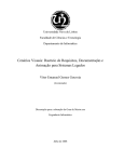
Section 1
Specifications
1.1 Mechanical
Diameter
5.66 cm
Length
5.46 cm
Depth rating
2000 m
Temperature range
-2–38 °C
Storage temperature range
-20–50 °C
Weight in air
0.34 kg
Displacement
137 ml
Pressure housing
Titanium 6Al-4V
1.1.1 6-contact connector
Contact
Function
1
Ground
2
RS232 RX
3
Reserved
4
Voltage in
5
RS232 TX
6
Reserved
MCBH-6-MP
1.2 Electrical
Input
7–15 VDC
Current draw
81 mA
Linearity
99%
1.3 Communications
Sample rate
1 Hz
RS232 output rate
19200 baud
Output resolution
14 bit
1.4 Optical
Parameter
Wavelength EX/EM
Range, Sensitivity
Chlorophyll (Chl)
470/695 nm
0.005–250, 0.005 µg/L
Fluorescent Dissolved Organic Matter (FDOM)
370/460 nm
0.03–900, 0.03 ppb QSDE
Backscattering
700 nm
0–0.04 m-1 sr-1, 1E-06 m-1 sr-1
Crude oil limit of detection, sensitivity
< 80, 3 ppb
3
Specifications
4
Section 2
Operation and maintenance
2.1 Verify operation
WARNING
DOM sensors use an ultraviolet LED light source. Do not look directly at a UV LED when it is on. It
can damage the eyes. Keep products that have UV LEDs away from children, pets, and other
living organisms. Wear polycarbonate UV-resistant safety glasses to protect the eyes when a UV
LED is on.
CAUTION
Do not supply more than 15 VDC to the sensor. More than 15 VDC will damage the sensor.
Make sure that the sensor operates before further setup and deployment.
1. Connect the sensor to a PC that has a terminal program such as Tera Term or
HyperTerminal® installed. Refer to Get and install terminal program on page 7 for
instructions to get, install, and use a terminal program.
2. Remove the cap that protects the sensor's optical face.
3. Connect the sensor to a regulated power supply set at 12 VDC.
4. Turn on the power supply.
The sensor comes on.
5. Start the terminal program on the PC.
6. Select the appropriate "COM Port" in the terminal program.
7. Select the correct serial port settings in the terminal program.
•
•
•
•
•
baud rate: 19200
stop bits: 1
data bits: 8
flow control: none
parity: none.
Data shows in the terminal window.
8. To stop the data, select File, then Disconnect (Tera Term).
The data stops.
9. To close the program, select File, then Exit.
2.2 Set up for deployment
1. Refer to the previous section to make sure that the sensor operates correctly.
2. If necessary, remove the protective cap from the sensor.
3. Use an external power supply to supply power to the sensor for deployment.
2.3 Sensor maintenance
CAUTION
Do not use acetone or other solvents to clean any part of the sensor.
1. After each cast or exposure to natural water, flush the sensor with clean fresh water.
2. Use soapy water to clean any grease or oil on the optical face of the sensor. It is
made of plastic and optical epoxy and can be damaged if an abrasive cleaner is
used.
3. Dry the sensor with a clean soft cloth.
5
Operation and maintenance
2.3.1 Clean and lubricate bulkhead connector
Lubricate the contacts of bulkhead connectors at regular intervals with pure silicone spray
only. Allow the contacts to dry before they are connected.
Make sure that the pins have no corrosion, which looks green and dull. Make sure that
the rubber seals on the pins are not delaminated. Connectors should connect smoothly
and not feel "gritty" or too resistant.
The manufacturer recommends 3M™ Silicone Lubricant spray (UPC 021200-85822).
Other silicone sprays may contain hydrocarbon solvents that damage rubber.
DO NOT use silicone grease. DO NOT use WD-40®. The wrong lubricant will cause
failure of the bulkhead connector and the sensor.
6
Section 3
Reference
3.1 Delivered items
•
•
•
•
the sensor
a lock collar
a plastic protective cover for the optical face
the CD, with:
•
•
this user manual
the characterization/calibration page for the sensor.
3.2 Calibration
The manufacturer calibrates all scattering sensors to make sure that the data that is
collected meets the sensor's specifications. This information is on the sensor-specific
calibration page that comes with the sensor.
3.3 Characterization
The manufacturer uses a fluorescent material to characterize all fluorescence sensors to
make sure that the data that is collected meets the sensor's specifications. This
information is on the sensor-specific characterization page that comes with the sensor.
3.4 Terminal program operation
Use Windows HyperTerminal®, Tera Term, or other terminal program to operate sensors.
baud rate: 19200
stop bits: 1
data bits: 8
flow control: none
parity: none
3.4.1 Get and install terminal program
Get and install a terminal communications program to communicate between the PC and
the sensor. The steps below refer to Tera Term, an open-source terminal emulator
program, but the set up and protocols are similar for other terminal communications
programs.
1. Do the steps on the web site www.ayera.com/teraterm/download.cfm to get the
software.
2.
3.
4.
5.
a. Enter the required information on the web site.
b. Select "Save As" to save the software to a user-selected location on the PC.
c. Right-click on the .zip file and select "Extract all..."
Go to the extracted files and double-click on the ttermpro.exe file.
Push Run.
Push OK in the Tera Term: New connection window.
In the Tera Term Web 3.1 - COMx VT window, go to Setup, then Serial port...
• Port: user-selected COM x
• Baud rate: 19200
• Data: 8 bit
• Parity: none
• Stop: 1 bit
• Flow control: none
• Transmit delay, msec/char: 2
• Transmit delay, 50 msec/line
6. Push OK.
7
Reference
7. To view commands as they are entered, go to the Setup menu, then Terminal... and
put a check in the box next to "Local echo."
8. To save this setup, go to the Setup menu, then Save setup....
9. Enter a new "File name," or push Save to save the default "teraterm.ini" setup file
name.
10. Connect the sensor to a power supply set at 12 VDC and PC.
Refer to Verify operation on page 5 for details.
11. Make sure that the terminal program is open.
12. Turn the power supply on.
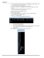
13. Enter 5 exclamation points (! ! ! ! !) to put the sensor in an operational mode.
The software shows 14 columns of data.
14. Enter ! ! ! ! ! to stop the sensor.
The menu of the sensor shows below the collected data.
• ser: serial number of the sensor
• ver: version of installed firmware
• ave: the number of measurements that are averaged to make up one row of data.
• seq: the manufacturer-set sequence in which data is output.
• rat: baud rate
15. Enter $par to see the settings that are saved in the sensor.
8
Reference
16. Enter $run to start the sensor.
The sensor collects and shows data.
17. Find the offset, or dark counts value of the sensor for data correction.
3.4.1.1
Find sensor offset value
Use the power supply that the sensor will use for deployment to find the offset value of
the sensor output. It is possible that the offset given by the manufacturer is different
because the sensor is very sensitive in terms of both input and output.
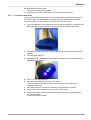
1. Cover the detectors on the optical face of the sensor with Scotch 33™ electrical tape.
Make sure that the tape does not cover any part of the LED optical bore holes.
2. If necessary, connect the sensor to the PC and power supply and start the terminal
program.
3. Turn the power supply on.
4. Enter $run, then push Enter to start the sensor operation. Let the sensor operate for
approximately 60 seconds.
5. Enter ! ! ! ! ! to stop the sensor.
6. Calculate the average each of column 4, 8, then 13.
These averages are the offset ("dark counts") values to use for chlorophyll,
scattering, and FDOM.
7. Save these values to use when the data from a deployment is processed.
8. Remove the electrical tape from the optical face of the sensor.
9. Use a lint-free wipe and isopropyl alcohol to gently clean any remaining adhesive
from the optical face.
The sensor is ready to deploy.
9
Reference
3.4.2 Common terminal commands
Command
Parameters
Description
!!!!!
none
Stops data collected by the sensor. Lets the user to enter setup values.
If the sensor is in a low-power mode, turn the power supply off for one minute, then turn the
power on and push the "!" key 5 or more times.
$ave
1–65535
The number of measurements that make up each row of collected data.
$mnu
—
Prints the menu of setup values to the host PC screen.
$pkt
0–65535
Sets the number of rows of data that are collected between the specified time intervals.
$run
—
Uses the current setup values to operate.
$sto
—
Saves the desired setup values to the sensor's flash memory.
3.4.3 SeaOWL UV-A-specific terminal commands
Command
Parameters
Description
$met
none
Prints a report of meta data for the current output sequence
$par
none
Prints the timing and conversion parameters
$rfd
none
Reloads the manufacturer's settings
$rls
none
Reloads the settings from the flash memory
$seq
0–3
Sets the sequence bank to use to define the output
$tst
none
Prints "test"
10
Section 4
General information
Revised editions of this user manual are on the manufacturer's website.
4.1 Warranty
This sensor is warranted against defects in materials and workmanship for one year from
the date of purchase. The warranty is void if the manufacturer finds the sensor was
abused or neglected beyond the normal wear and tear of deployment.
4.2 Service and support
The manufacturer recommends that sensors be sent back to the factory annually to be
cleaned, calibrated, and for standard maintenance.
Refer to the website for FAQs and technical notes, or contact the manufacturer for
support at:
[email protected]
Do the steps below to send a sensor back to the manufacturer.
1. Contact the manufacturer for a Return Merchandise Authorization (RMA).
Note: The manufacturer is not responsible for damage to the sensor during return shipment.
2. Remove all anti-fouling treatment from the sensor before sending it back to the
manufacturer.
Note: The manufacturer will not accept sensors that have been treated with anti-fouling
compounds for service or repair. This includes tri-butyl tin, marine anti-fouling paint, ablative
coatings, etc.
3. Use the sensor's original ruggedized shipping case to send the sensor back to the
manufacturer.
4. Write the RMA number on the outside of the shipping case and on the packing list.
5. Use 3rd-day air to ship the sensor back to the manufacturer. Do not use ground
shipping.
6. The manufacturer will supply all replacement parts and labor and pay to send the
sensor back to the user via 3rd-day air shipping.
4.3 Waste electrical and electronic equipment
Electrical equipment that is marked with this symbol may not be disposed of in European public
disposal systems. In conformity with EU Directive 2002/96/EC, European electrical equipment
users must return old or end-of-life equipment to the manufacturer for disposal at no charge to
the user. To recycle, please contact the manufacturer for instructions on how to return end-oflife equipment, manufacturer-supplied electrical accessories, and auxiliary items for proper
disposal.
11
General information
4.4 Tera Term BSD license
Tera Term is used under a BSD open source license.
12
WET Labs, Inc.
P.O. Box 518
Philomath, OR 97370 U.S.A.
Tel. (541) 929-5650
Fax (541) 929-5277
www.wetlabs.com
©
WET Labs, Inc. , 2015. All rights reserved. Printed in U.S.A.
*SeaOWL
UV-A150901*